Article

Development of a SnS Film Process for Energy Device Applications

1
Division of Materials Science and Engineering, Hanyanag University, Seoul 04763, Korea
2
Division of Nanoscale Semiconductor Engineering, Hanyang University, Seoul 04763, Korea
*
Author to whom correspondence should be addressed.
Appl. Sci. 2019, 9(21), 4606; https://doi.org/10.3390/app9214606
Submission received: 30 August 2019 / Revised: 23 October 2019 / Accepted: 25 October 2019 / Published: 29 October 2019
(This article belongs to the Special Issue Atomic Layer Deposition for the Synthesis of Thin Films)

Abstract

:
Tin monosulfide (SnS) is a promising p-type semiconductor material for energy devices. To realize the device application of SnS, studies on process improvement and film characteristics of SnS is needed. Thus, we developed a new film process using atomic layer deposition (ALD) to produce SnS films with high quality and various film characteristics. First, a process for obtaining a thick SnS film was studied. An amorphous SnS2 (a-SnS2) film with a high growth rate was deposited by ALD, and a thick SnS film was obtained using phase transition of a-SnS2 film by vacuum annealing. Subsequently, we investigated the effect of seed layer on formation of SnS film to verify the applicability of SnS to various devices. Separately deposited crystalline SnS and SnS2 thin films were used as seed layer. The SnS film with a SnS seed showed small grain size and high film density from the low surface energy of the SnS seed. In the case of the SnS film using a SnS2 seed, volume expansion occurred by vertically grown SnS grains due to a lattice mismatch with the SnS2 seed. The obtained SnS film using the SnS2 seed exhibited a large reactive site suitable for ion exchange.

1. Introduction

SnS is a tin compound with desirable qualities such as nontoxicity, low cost, and good hydrolytic stability [1,2,3]. SnS has been actively studied due to its p-type semiconductor characteristics and remarkable optoelectronic properties. Particularly, the low process temperature of the tin compound is a great advantage. The use of a low process temperature improves the process efficiency, prevents device degradation, and enables application on flexible substrates. Crystallographically, SnS has a double-layered orthorhombic structure under usual process conditions, as shown in Figure 1a. Atoms are covalently bonded in the planar layers, and individual layers are bonded by van der Waals forces. The orthorhombic structure has two carrier paths perpendicular to each other along the basal plane [4]. One path has zigzag shape, and the other is called the armchair direction. In the case of physical properties, SnS thin films generally have a carrier concentration of 1015 to 1017 cm−3, carrier mobility greater than 15 cm2/Vs, a strong absorption coefficient greater than 104 cm−1 in the visible region, and a bandgap of 1.4 eV [2,5,6,7,8,9]. Some simulation studies have shown that SnS has an indirect bandgap of 1.1 eV, but most experimental results have shown a direct bandgap of 1.4 eV. Thus, the value of 1.4 eV is considered as a typical band gap of SnS. [10]. Additionally, SnS exhibits intrinsic p-type semiconductor characteristics due to tin vacancies [8,11,12].
SnS is a strong candidate material for various energy devices, such as solar cells, batteries, water splitting devices, and thermoelectrics, due to the excellent optoelectronic properties and stable p-type characteristics [13,14,15,16,17,18,19,20,21]. However, studies of SnS for energy device applications do not show good performance corresponding to the optoelectronic characteristics of SnS. At present, atomic layer deposition (ALD) is suitable for verifying the applicability of SnS to various device applications. This is due to the characteristics of ALD process suitable for high quality film deposition. However, target applications require a greater film thickness than the nanometer scale. The ALD method is known as a slow deposition method and is suitable for nanometer-scale thin-film processes. Specifically, the highest efficiency record of a SnS solar cell was based on the ALD method, but the SnS study using ALD is not active. In that research, the growth rate of the ALD SnS process was 0.9 Å/cycle, and the deposition of a 500 nm thick SnS film required a long deposition time [2,22]. Other ALD SnS studies have showed lower growth rates of 0.24 to 0.36 Å/cycle [23,24,25,26]. The growth rate of general films deposited with ALD is about 1 Å/cycle, but the growth rates of ALD-deposited SnS films are lower than 1 Å/cycle. Therefore, the development of SnS studies for energy devices requires a new process for a thicker, high-quality film.
In addition, studies on crystal growth behaviors and film characteristics of SnS films are insufficient. Because SnS is formed as a crystalline film and has a two-dimensional structure, it is difficult to control the characteristics of the film in the process. Due to the planar growth characteristic of orthorhombic structure, the defects are more exacerbated at the grain boundaries compared with other polycrystalline films [27,28]. Defects between planar grains cause shunt loss in solar cells and retard the carrier transport in the devices. Additionally, for electrochemical applications, films with vertically grown grains have advantages due to their large ion exchange area [29,30]. However, the planar growth trend of SnS film is different from this demand. Therefore, to apply SnS to energy devices, it is necessary to obtain a defect-free film and control the grain growth of the SnS film according to the various applications.
As the described problems coexist, the research on SnS remains stagnant. Therefore, we present an efficient thick-film process using ALD and a method of grain growth control to optimize the film characteristics. In the ALD process using tetrakis (dimethylamino) tin (Sn[N(CH3)2]4, TDMASn) precursor and H2S reactant, three crystal phases of amorphous SnS2 (a-SnS2), crystalline hexagonal SnS2, and crystalline orthorhombic SnS can be obtained depending on the deposition temperature. The ALD process using tetrakis (dimethylamino) tin and H2S was first reported by Ham et al. [31]. In the report, amorphous SnSx films were deposited at temperature below 120 °C. At the deposition temperature of 140 and 150 °C, hexagonal SnS2 phase was observed. Further, orthorhombic SnS films were deposited at the temperature of 160 and 180 °C. As the deposition temperature increased, the crystallinity of thin film increased, and the growth rate decreased. Although the composition of amorphous SnSx is not described, X-ray photoelectron spectroscopy (XPS) results showed that the SnSx film had SnS2 bond. This SnS2 bond was identified again in this study. Here, the a-SnS2 with a high growth rate was deposited and annealed in a vacuum atmosphere to form a thick SnS film using phase transition. Through this method, we obtained a thick SnS film with the advantages of ALD, such as uniformity and conformality. In addition, changes in grain growth behaviors in the SnS film were performed using the ALD-deposited crystalline SnS and SnS2 seed layers. All the processes were performed in the same chamber as an in-situ process. The entire SnS film had phase continuity because the vacuum annealing results of crystalline SnS and SnS2 were also SnS phase.

2. Materials and Methods

a-SnS2 films were prepared by the vapor deposition method using ALD-type recipe at the deposition temperature of 100 °C. We used TDMASn as a tin precursor and hydrogen sulfide (H2S, 99.9%) as a sulfur reactant. The TDMASn was maintained at 50 °C, and argon gas was supplied at a flow rate of 30 sccm as a bubbler gas. The substrates were thermally oxidized 300 nm thick SiO2/Si wafer and glass. The process pressure was maintained at 1.0 Torr by purging with argon gas, and the following recipe was used: (T 0.5s–P 10s–T 0.5s–P 10s)–(S 0.5s–P 10s–S 0.5s–P 10s), where T is TDMASn, P is purge, and S is H2S. When this process recipe and pressure were used at the deposition temperature of amorphous phase SnS2, higher growth rates were observed than typical ALD methods. We deposited 935 cycles to obtain a 500 nm thick a-SnS2 film. Subsequently, the annealing processes were performed in the ALD chamber with a vacuum atmosphere of 10−3 Torr at various temperatures and different annealing times (300, 400, and 500 °C for 10 min; 400 °C for 5, 10, 20, and 30 min). For all annealing processes, the target temperature was reached in 10 min from deposition temperature of a-SnS2, i.e., 100 °C. Then, 450 nm thick a-SnS2 films were deposited on each of the 50 nm crystalline SnS and SnS2 seed layers. When we deposited the seed layers, the temperatures of 150 and 170 °C were used as deposition temperatures of crystalline SnS2 and SnS films, respectively. We performed 1461 cycles for 50 nm crystalline SnS and 1740 cycles for 50 nm crystalline SnS2; other deposition conditions were the same as the deposition process of a-SnS2. Unlike the case of a-SnS2, the deposition of crystalline phase SnS and SnS2 films showed low growth rates consistent with the characteristics of ALD. These samples were also subsequently annealed at 400 °C for 10 min. The reactor was a showerhead-type chamber for four-inch wafer deposition manufactured by ASM Genitech Korea, Hwaseong, Korea. Reactant gases flowing from the left lines were sent to the upper part and injected into the chamber through the showerhead. The exhaust was located at the right bottom part of the chamber. The changes of the crystalline phase, crystallinity, and crystalline growth orientations were examined by an X-ray diffraction (XRD) analyzer with Cu Kα radiation (λ = 1.54 Å) using θ–2θ scan, and XPS was used for the identification of chemical bonding states. Film morphology and uniformity were investigated using scanning electron microscopy (SEM). Ultraviolet-visible spectroscopy (UV–vis), a Hall effect measurement system, and a contact angle tester were used for identification of optical properties, electrical characteristics, and surface wettability, respectively.

3. Results and Discussion

3.1. Development of a Process Proper for Obtaining a Thick SnS Film Using ALD

We first performed a vacuum annealing process of ALD-deposited a-SnS2 film to fabricate the thick SnS film. The XRD patterns, shown in Figure 1b,c, exhibited the dependence of temperature and time conditions on the vacuum annealing process, respectively. As shown in Figure 1b, when the a-SnS2 films were annealed at various temperatures for 10 min, crystalline SnS phases were observed at 400 and 450 °C. The XRD peaks of samples annealed at 400 and 450 °C indicated orthorhombic SnS corresponding to diffraction data reference of JCPDS standard card #23-0677. In particular, the XRD pattern of the film annealed at 400 °C for 10 min was almost the same as that of the JCPDS reference, and the peaks became sharp. At the annealing temperature of 350 °C, the phase transition from SnS2 to SnS was also observed. However, the a-SnS2 film was not completely transformed into crystalline SnS. The main (001) peak of hexagonal SnS2 phase was observed at 15.03°. Further, there were additional low intensity peaks positioned at 16.10°, 21.48°, 28.80°, 33.78°, 40.12°, and 50.08°. These are peaks of orthorhombic Sn2S3 crystal phase found in JCPDS #75-2183. Because Sn2S3 generally appears as a mixed phase in tin sulfide films, it is interpreted that Sn2S3 crystals appeared as a metastable phase in the intermediate step of the transformation of SnS2 to SnS. Alternatively, the Sn2S3 as a phase impurity contained in a-SnS2 film may have been crystallized. As the annealing temperature was increased above 400 °C, the sharpness of SnS peaks decreased, and no peaks were observed at 500 °C. In an actual experiment, it was identified that the a-SnS2 film completely volatilized on the substrate at the annealing temperature of 500 °C. Therefore, 400 °C was the optimal annealing temperature, as shown in Figure 1b. Figure 1c shows the XRD results of a-SnS2 films annealed with various time conditions at 400 °C. As shown in Figure 1b, when the annealing time was 10 min, almost the same SnS crystal phase as the JCPDS reference was observed. The a-SnS2 film annealed for 5 and 20 min showed SnS peaks with lower sharpness than the sample annealed for 10 min. The main (001) peak of hexagonal SnS2 and the peaks of Sn2S3 were also detected in the 5 min annealed sample. Further, the sample annealed for 30 min was completely volatilized on the substrate. Thus, Figure 1b,c show that the a-SnS2 film completely transformed into a polycrystalline SnS film under the annealing conditions of 400 °C for 10 min.
The crystallization behavior in this experiment was different from our previous reports that directly deposited SnS film by ALD, which showed only a main (111) peak of orthorhombic SnS phase at 31.53° [25]. Furthermore, this process used a high growth rate of 5.3 Å/cycle. Compared to the previous study, the growth rate of this a-SnS2 process was very high. In an earlier study on atomic layer deposition of tin sulfide films using TDMASn and H2S by Ham et al., tin sulfide film deposited at 100 °C had growth rate of 1.26 Å/cycle [31]. At our ALD process used in this study, higher process pressure of 1.0 Torr and multidosing recipe were used, as described in the methods section. As the amorphous phase was deposited at a low temperature of 100 °C, the differences of pressure and recipe would increase the growth rate compared to the previous study. In particular, the multidosing method could support the ideal layer-by-layer adsorption in crystalline thin-film deposition but would cause a contribution of chemical vapor deposition (CVD) reaction in the deposition of an amorphous phase film at low temperature. Therefore, CVD contribution could not be completely excluded in the deposition process of a-SnS film in this study. However, this process has a sufficiently high film quality compared to other deposition methods through the use of ALD recipe. Therefore, this process of a-SnS2 could have advantages as an intermediate method between ALD and CVD.
As observed in the XRD results in Figure 1b,c, an increase of the temperature or time from the annealing condition of 400 °C and 10 min reduced the SnS peak. Specifically, bulk SnS evaporates at a temperature above 485 °C in a vacuum of 10−3 mbar (= 1.33 × 10⁻³ Torr), but the raw material used in this study was an amorphous and directly deposited film [32]. Therefore, SnS crystals formed by vacuum annealing could also evaporate at temperatures below 485 °C. XRD results showed that the SnS crystals evaporated above 400 °C. Excessive annealing temperature or time increase at conditions of 400 °C and 10 min could result in crystallite size reduction and defect formation in the SnS film. On the contrary, when the annealing temperature and time were less than 400 °C or less than 10 min, the peaks of hexagonal SnS2 and orthorhombic Sn2S3 appeared. The SnS2 and Sn2S3 peaks indicate that other tin sulfide crystal phases are mixed in the SnS film when the thermal energy for phase transition is insufficient. The reason for the noticeable phase mixing during the tin sulfide process is the small chemical stability difference between SnS and SnS2. In group 14, valence s electrons tend to be unionized or unshared according to the atomic weight due to the weak shielding effect of d and f orbitals in the inner cells. These characteristics correspond to the inert pair effect of the post transition metals. For example, Pb has atomic number of 82 and constitutes PbS as a stable phase. In the case of Sn, located directly above Pb in the periodic table, SnS2 is a stable phase, but the difference of stability between SnS and SnS2 is small. Therefore, for the process of tin sulfide film, it is important to optimize the process to obtain a pure phase. Additionally, a-SnS2 film crystallized first during the vacuum annealing process rather than the phase transition to SnS. Thus, untransformed SnS2 grains were detected as a crystallized phase. Considering the evaporation of the SnS film and the required energy for phase transition from SnS2 to SnS, further study can be performed using a vacuum annealing time longer than 10 min at a temperature below 400 °C. In this paper, the annealing condition of 400 °C and 10 min was considered as an optimal process condition, and subsequent analyses were performed using samples formed by the annealing condition.
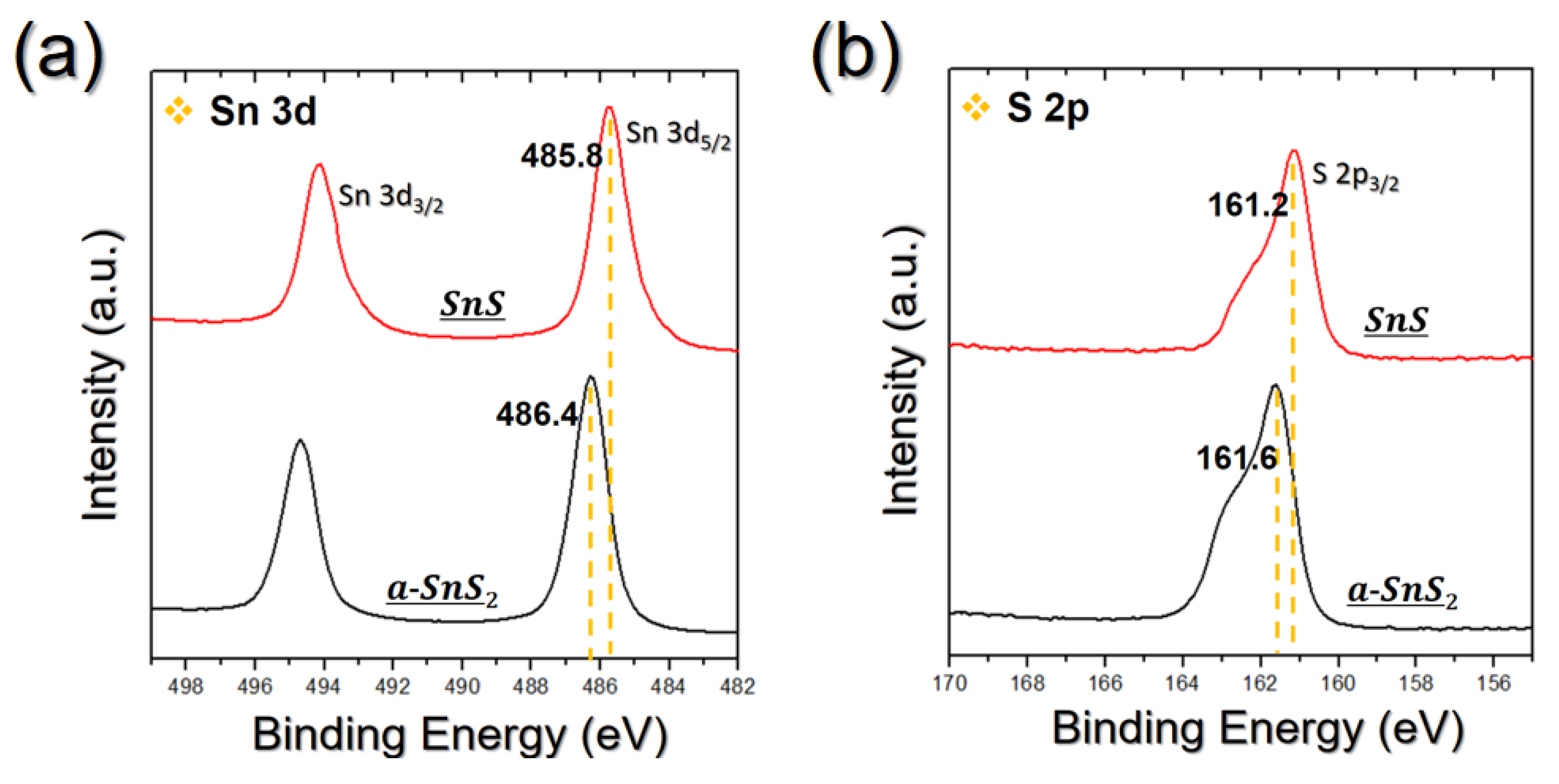
Figure 2a,b shows the XPS result of ALD a-SnS2 film and the SnS film formed by vacuum annealing. To eliminate surface contamination, the films were etched 3 nm from the surface by argon sputtering. The derived data were calibrated based on carbon 1s peak (284.5 eV). The Sn 3d5/2 peaks of a-SnS2 and SnS were positioned at 486.4 and 485.8 eV, respectively. Because Sn4+ has a higher positive oxidation state than Sn2+, SnS2 exhibits a higher binding energy due to extra Coulombic interactions. The S 2p3/2 peak position of a-SnS2 was 161.6 eV and shifted to 161.2 eV after transformation to SnS. The distance between Sn 3d5/2 and S 2p3/2 was 324.8 eV for a-SnS2 and 324.6 for SnS. The binding energies of both films were similar to the representative reference, as summarized in Table 1. The similar peak positions of a-SnS2 with reference data indicates that the impurity contents were very small despite the low deposition temperature. The advantage of the ALD method is shown here. As a result, the binding energy of the two films chemically showed that a-SnS2 films were entirely transformed into the SnS phase.
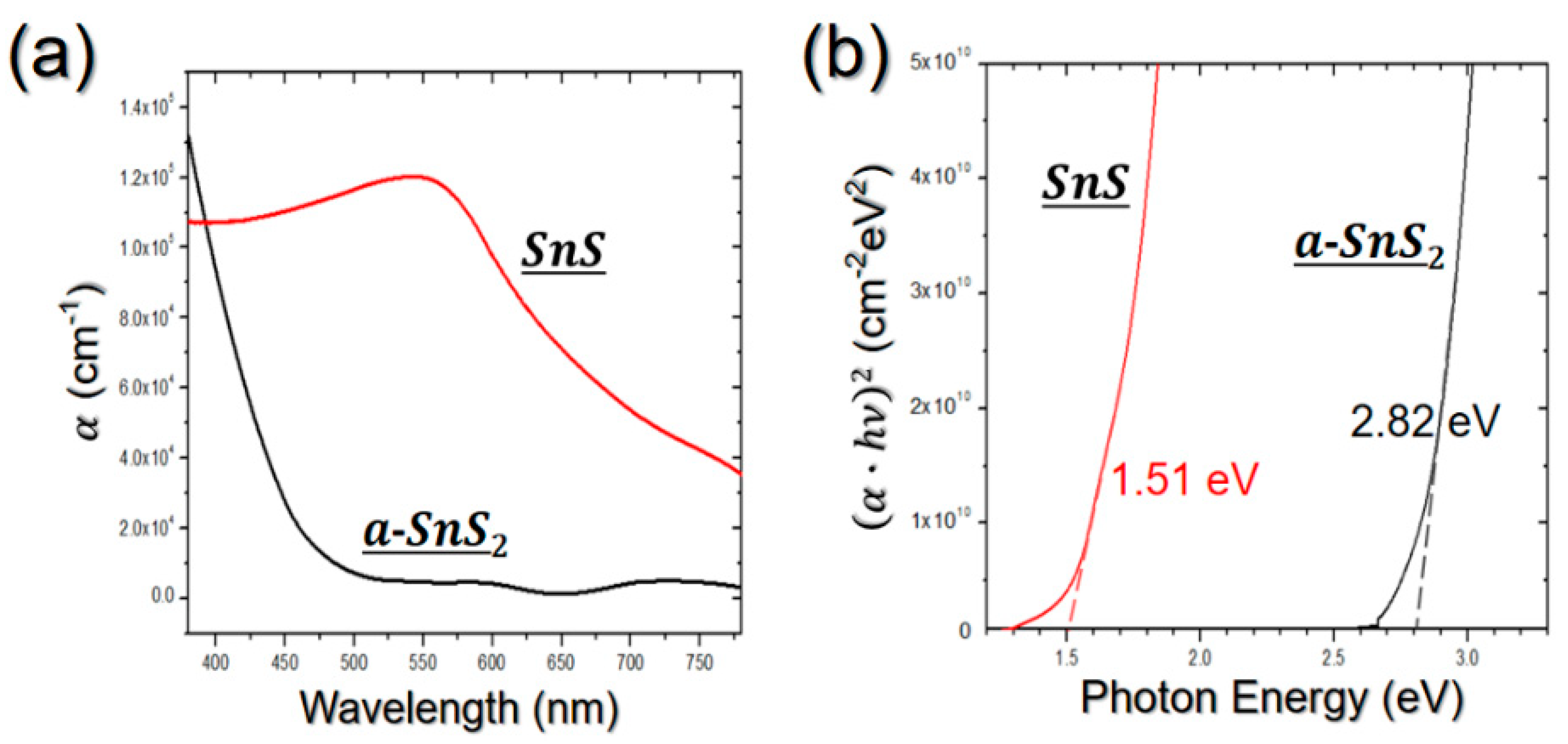
As shown in Figure 3a,b, UV–vis analysis was performed to identify the optical properties of a-SnS2 and SnS films. The films were deposited on a glass substrate, and the obtained results were calibrated based on absorbance of the glass substrate. Figure 3a exhibits the absorption coefficient of a-SnS2 and SnS films in visible region. The 500 nm thick a-SnS2 film had an absorption coefficient of 3.3 × 10³ to 1.3 × 105 cm−1. When the a-SnS2 film transformed into SnS film, the absorption coefficient was 3.6 × 10⁴ to 1.1 × 105 cm−1. After the phase transition from a-SnS2 to SnS, the absorption coefficient of the film increased by 10 times on average.
Furthermore, the direct bandgaps of the a-SnS2 and SnS films were identified in Figure 3b using the following equation:
( α h ν ) n = ( h ν E g ± E p h )
where Eg, Eph, and n are optical bandgap, photon energy, and transition probability, respectively. In the case of direct transition, n has an order of 2 for the allowed transition, and Eph is 0 eV. Thus, the optical bandgap can be obtained by the plot of (αhν)2. Figure 3b exhibits a plot of (αhν)2 as a function of photon energy to determine the absorption coefficients of a-SnS2 and SnS films. When (αhν) = 0, the photon energy indicates an optical bandgap. The bandgap of the a-SnS2 film was 2.82 eV, and it decreased to 1.51 eV after transformation from a-SnS2 into SnS by vacuum annealing. The obtained bandgaps were similar with typical bandgaps of SnS2 and SnS films [5,6,7,33,34]. Through UV–vis analysis, we also identified the phase transition from SnS2 into SnS and the optical properties of both films.
Further uniformity testing of the SnS film process was performed. Figure 4a is a schematic image of the showerhead-type ALD chamber used in this study. In this uniformity test, a 500 nm thick a-SnS2 film was deposited on a four-inch scale thermally oxidized SiO2/Si wafer. SnS film was formed by annealing the a-SnS2 film. The thicknesses of the 16 positions on the wafer were measured by SEM, as shown in Figure 4b. To determine the uniformity, we used the typical equation below:
Uniformity = T m a x T m i n 2 T a v e × 100 %
Average thickness of the points was 496.65 nm, and obtained uniformity was ±2.61%. Although we used a higher growth rate process than that of the conventional ALD process, it was identified that a uniform film process was obtained.

3.2. Process to Control the Film Characteristics of SnS Film Using Seed Layer

This section shows the changes in grain growth behavior in SnS film by crystalline SnS and SnS2 seed layers. The first reason to use SnS and SnS2 thin films as seed layers is that they can be deposited by the ALD process using the same precursor and reactants as a-SnS2. Thus, all the processes can be performed continuously in the same chamber. Second, as the vacuum annealing process results of SnS and SnS2 are both SnS phase, there is no discontinuity in the finally formed SnS film. In the case of studies using other seed layers, the seed layer remains in the SnS film. The remaining seed layer can finally affect the operation of devices. In this study, three SnS films were prepared by the method shown in Figure 5a. The samples were the nonseeded SnS film (sample A) obtained previously, SnS film using a crystalline ALD SnS seed layer (sample B), and SnS film using a crystalline ALD SnS2 seed layer (sample C). The seed layer and a-SnS2 films were continuously deposited by changing the substrate temperature and annealed at 400 °C for 10 min in a vacuum atmosphere. The thickness of the deposited seed layer was 50 nm, and the total thickness of a-SnS2 with the seed layer was 500 nm.
First, formation of the SnS phase was identified when only seed layers were annealed at 400 °C for 10 min in a vacuum atmosphere. Figure 5b shows the XRD results before and after vacuum annealing of the 50 nm ALD SnS and SnS2 seed layers. SnS and SnS2 seed layers showed the (111) SnS peak at a Bragg angle of 31.53° and the (001) SnS2 peak at a Bragg angle of 15.03°, respectively. The seed tin sulfide films were highly oriented along the direction of the main peak. In addition, SnS and SnS2 seed layers exhibited a main peak of SnS at 31.53° after vacuum annealing. The crystallinity of the seed SnS thin film increased with sharpening of the (111) SnS peak. The seed SnS2 thin film was transformed into crystalline SnS phase after vacuum annealing and showed the (111) peak at 31.53°.
Figure 5c shows the XRD analysis of the three SnS films using the seed layer. The SnS film using SnS seed layer (sample B), exhibited a very sharp and intensive (111) peak of SnS at 31.53°. Other SnS peaks appeared very small. Based on the XRD results, it can be estimated that the SnS seed transformed a-SnS film into a very highly crystalline SnS film, but the SEM images show that this interpretation is incorrect. Figure 5d–f is the SEM images of the three SnS films using various seed layers. In the top view of the SEM images, sample B showed very small and densely packed grains compared to the nonseeded SnS film (sample A). Therefore, the sharp SnS main peak of sample B shown in Figure 5c is mainly due to the peak of the SnS seed layer shown in Figure 5b. The grain size reduction and increased packing density of the SnS film are due to the surface energy of the SnS seed layer. Figure 6a exhibits the result of the water contact angle test to compare the surface energies of the SiO2 substrate and SnS and SnS2 seed layers. The contact angle of the SiO2 substrate and SnS seed layer were 41.4° and 77.1°, respectively. The high contact angle of the SnS seed layer indicates that the SnS seed had a lower surface energy than the SiO2 substrate. As the surface energy of the SnS seed layer was much smaller than that of the SiO2 substrate, grains of the SnS film formed on the SnS seed were also smaller than grains of the SnS formed on SiO2. Furthermore, since the SnS seed layer was in the same phase with the SnS film as a final target, there was no lattice mismatch between crystallized SnS and SnS seed. Thus, only the surface energy of the seed layer was expected to contribute to the crystallization behavior of a-SnS2 film. The induced strain by surface energy change of the SnS seed should also be considered, but the change in contact angle of the SnS seed by annealing was relatively small. Additionally, the defect reduction of the SnS film was expected due to the increase in film density.
The SnS film using the SnS2 seed layer (sample C) showed peaks of the orthorhombic SnS crystal phase at the same Bragg angles as sample A. In the case of sample C, the main (111) peak at 31.53° was expected to include the peak of the annealed SnS2 seed layer as in sample B. Notably, the intensity and sharpness of peaks other than the (111) peak were increased compared to sample A. For simple comparison, the crystallite sizes for each XRD peak of three SnS samples are summarized in Table 2. The crystallite sizes were calculated by the Scherrer formula using full width half maximum (FWHM) of each peak. The calculated crystallite size is not an actual grain size but a numerical value for simple comparison. This is because the crystals assumed in the Scherrer formula are particles having spherical shape. In films, the crystallite size calculated by the Scherrer formula is used only to relatively compare the grain growth according to orientation. FWHMs were determined using a PDXL 2.0 Rigaku, Tokyo, Japan. As shown in the Table 2, the crystallite sizes at the Bragg angle of 27.47° (021), 39.04° (111), and 45.49° (002) of sample C were larger than the crystallite sizes of sample A. The grain growth of the (111) orientation at 31.53° in sample C cannot be interpreted as increased because it includes the annealing result of the SnS2 seed layer shown in Figure 5b.
As can be seen from the SEM image given in Figure 5f, the SnS grains grew vertically on the substrate and showed a porous film. To reduce the high strain caused by lattice mismatch between the SnS grains and the SnS2 seed, the SnS grains grew with a distorted direction at the interface of the a-SnS2 and SnS2 seeds. In the intermediate step when using the SnS2 seed layer, shown in Figure 6b, the strain due to lattice mismatch is resolved by reducing the atomic interaction with the SnS2 seed layer. If the a-SnS2 comprised a very thin film, then a polycrystalline SnS film would be formed at this step. However, because the a-SnS2 film was a 500 nm thick film, the strain in the film could not be fully resolved due to the overlaps of grains. Eventually, the grains were aligned vertically to the substrate, exposing edge sites to minimize the strain by the overlap of grains [29]. As described in the introduction, SnS grains have a higher growth rate in the direction of basal plane than the growth rate in the direction of stacking layers due to the characteristics of 2D structure. Thus, volume expansion of the film occurred by vertical growth of grains. The thickness of sample C was 734.70 nm, which was significantly increased from the thickness of 500 nm before annealing. Due to this grain direction change, sample C showed sharper suborientation peaks than sample A in the XRD results.
As can be seen in Figure 6a, the contact angle of the SnS2 seed layer was also larger than the contact angle of the SiO2 substrate. However, because the influence of the lattice mismatch was dominant, the grain size was not reduced as in sample B. In addition, the contact angle of the SnS2 seed layer did not change significantly after vacuum annealing. Therefore, the strain of the film due to the surface energy change is expected to be negligible. The reduction of lattice mismatch due to the phase transition of the SnS2 seed to the SnS phase could be discussed, but it also has lower priority. This is because the SnS2 seed layer deposited as the crystallized thin film requires more activation energy for transition to SnS than a-SnS2 film. Therefore, the transformation rate of the SnS2 seed is slower than that of the a-SnS2 film. Because the SnS process used a seed layer, sample B formed a denser film compared to sample A. The process using the SnS seed layer can reduce the problems of film defects, such as shunt loss in solar cells. However, the increase in grain boundaries due to the reduction in grain size resulted in a slight decrease in electrical properties, as shown in Table 3. The resistivity and mobility of sample B were 6.67 × 10⁻² Ωm and 11.50 cm2/Vs, respectively. The resultant electrical properties of sample B were lower than the resistivity of 4.96 × 10⁻² Ωm and the mobility of 32.67 cm2/Vs of sample A. Sample C had a resistivity of 5.13 × 10⁻² Ωm and mobility of 8.97 cm2/Vs, which is lower than that of sample A. The electrical properties of sample C were affected by vertically grown SnS grains and porous film characteristics. However, sample C had the advantage of film shape with increased reactive sites compared to conventional SnS films. Thus, sample C could be applied to electrochemical devices driven by ion exchange. Additionally, all the SnS films in this process showed carrier concentrations of the order of 1019 cm−3, which are higher than those of known SnS film studies by ALD due to the low resistivity via high film thickness. In practice, studies on thick SnS films have shown high carrier concentration between 1018–1019 cm−3 [35,36,37].
The process using seed layers requires additional modification of seed layer thickness. The use of SnS and SnS2 seed layers has the advantage that the entire thick SnS film formation process can be carried out continuously in one chamber. However, the growth rates of the seed layers were relatively lower than that of a-SnS2 film. Therefore, further research on the effects of thinner seed layer is needed, and optimal SnS film properties for various energy device applications should be determined by reducing the thickness of the seed layer.

4. Conclusions

We developed a new process for obtaining thick SnS films with a high growth rate of a-SnS2 film and the advantages of the ALD method, which was used to produce 500 nm thick SnS films from a-SnS2 films. The a-SnS2 films were entirely transformed into SnS films by vacuum annealing at 400 °C for 10 min. The transformation from a-SnS2 film into SnS film was identified using XRD and XPS analysis. In the measurement of optical properties by UV–vis, the SnS film had an absorption coefficient between 3.6 × 10⁴ and 1.1 × 105 cm−1 in the visible region, and the optical bandgap of the obtained SnS film was 1.51 eV. The uniformity of the SnS film in the process was ±2.61% on a four-inch scale SiO2/Si wafer. In addition, we investigated the effect of seed layer to optimize the characteristics of the SnS film for various applications. The SnS films with crystalline SnS and SnS2 seed layers exhibited various film properties. The SnS film using the SnS seed had small grain size and high film density due to the low surface energy of the SnS seed. In the case of the SnS film using the SnS2 seed, volume expansion of the film occurred in vertically grown SnS grains. The vertical grain growth of the SnS film was caused by lattice mismatch between the crystallized SnS grains and the SnS2 seed.

Author Contributions

Conceptualization, H.C.; methodology, H.C., N.L. and H.P.; formal analysis, H.C., Y.C. (Yeonsik Choi) and H.Y.; data curation, H.C., Y.C. (Yeonsik Choi) and K.K.; writing—original draft preparation, H.C., Y.C. (Yeongtae Choi), J.K. and S.S.; writing—review and editing, H.C., N.L. and H.P.; project administration, H.J.

Funding

This work was supported by the Nano Material Technology Development Program (2014M3A7B4049367) through the National Research Foundation (NRF) of Korea funded by the Ministry of Science and ICT (MSIT), Korea.

Conflicts of Interest

The authors declare no conflict of interest.

References

  1. Price, L.S.; Parkin, I.P.; Hardy, A.M.E.; Clark, R.J.H. Atmospheric Pressure Chemical Vapor Deposition of Tin Sulfides (SnS, Sn2S3, and SnS2) on Glass. Chem. Mater. 1999, 11, 1792–1799. [Google Scholar] [CrossRef]
  2. Sinsermsuksakul, P.; Heo, J.; Noh, W.; Hock, A.S.; Gordon, R.G. Atomic Layer Deposition of Tin Monosulfide Thin Films. Adv. Energy Mater. 2011, 1, 1116–1125. [Google Scholar] [CrossRef] [Green Version]
  3. Burton, L.A.; Whittles, T.J.; Hesp, D.; Linhart, W.M.; Skelton, J.M.; Hou, B.; Werster, R.F.; O’dard, G.; Reece, C.; Cherns, D.; et al. Electronic and optical properties of single crystal SnS2: An earth-abundant disulfide photocatalyst. J. Mater. Chem. A 2016, 4, 1312–1318. [Google Scholar] [CrossRef]
  4. Sucharitakul, S.; Kumar, U.R.; Sankar, R.; Chou, F.C.; Chen, Y.T.; Wang, C.; He, C.; Gao, X.P.A. Screening limited switching performance of multilayer 2D semiconductor FETs: The case for SnS. Nanoscale 2016, 8, 19050–19057. [Google Scholar] [CrossRef] [PubMed]
  5. Thangaraju, B.; Kaliannan, P. Spray pyrolytic deposition and characterization of SnS and SnS2 thin films. J. Phys. D Appl. Phys. 2000, 33, 1054–1059. [Google Scholar] [CrossRef]
  6. El-Nahass, M.M.; Zeyada, H.M.; Aziz, M.S.; El-Ghamaz, N.A. Optical properties of thermally evaporated SnS thin films. Opt. Mater. 2002, 20, 159–170. [Google Scholar] [CrossRef]
  7. Cifuentes, C.; Romero, E.; Calderon, C.; Gordillo, G. Optical and Structural Studies on SnS Films Grown by Co-Evaporation. Braz. J. Phys. 2006, 36, 1046–1049. [Google Scholar] [CrossRef]
  8. Burton, L.A.; Colombara, D.; Abellon, R.D.; Grozema, F.C.; Peter, L.M.; Savenije, T.J.; Dennler, G.; Walsh, A. Synthesis, Characterization, and Electronic Structure of Single-Crystal SnS, Sn2S3, and SnS2. Chem. Mater. 2013, 25, 4908–4916. [Google Scholar] [CrossRef]
  9. Kumagai, Y.; Burton, L.A.; Walsh, A.; Oba, F. Electronic Structure and Defect Physics of Tin Sulfides: SnS, Sn2S3, and SnS2. Phys. Rev. Appl. 2016, 6, 014009. [Google Scholar] [CrossRef]
  10. Burton, L.A.; Walsh, A. Phase Stability of the Earth-Abundant Tin Sulfides SnS, SnS2, and Sn2S3. J. Phys. Chem. C 2012, 116, 24262–24267. [Google Scholar] [CrossRef]
  11. Polizzotti, A.; Faghaninia, A.; Poindexter, J.R.; Nienhaus, L.; Steinmann, V.; Hoye, R.L.Z.; Felten, A.; Deyine, A.; Mangan, N.M.; Correa-Baena, J.P.; et al. Improving the Carrier Lifetime of Tin Sulfide via Prediction and Mitigation of Harmful Point Defects. J. Phys. Chem. Lett. 2017, 8, 3661–3667. [Google Scholar] [CrossRef] [PubMed] [Green Version]
  12. Malone, B.D.; Galibc, A.; Kaxiras, E. First principles study of point defects in SnS. Phys. Chem. Chem. Phys. 2014, 16, 26176–26183. [Google Scholar] [CrossRef] [PubMed]
  13. Park, H.H.; Heasley, R.; Sun, L.; Steinmann, V.; Jaramillo, R.; Hartman, K.; Chakraborty, R.; Sinsermsuksakul, P.; Chua, D.; Buonassisi, T.; et al. Co-optimization of SnS absorber and Zn (O, S) buffer materials for improved solar cells. Prog. Photovolt. Res. Appl. 2015, 23, 901–908. [Google Scholar] [CrossRef]
  14. Steinmann, V.; Jaramillo, R.; Hartman, K.; Chakraborty, R.; Brandt, R.E.; Poindexter, J.R.; Lee, Y.S.; Sun, L.; Polizzotti, A.; Park, H.H.; et al. 3.88% Efficient Tin Sulfide Solar Cells using Congruent Thermal Evaporation. Adv. Mater. 2014, 26, 7488–7492. [Google Scholar] [CrossRef] [PubMed]
  15. Reddy, K.T.R.; Reddy, N.K.; Miles, R.W. Photovoltaic properties of SnS based solar cells. Sol. Energy Mater. Sol. Cells 2006, 90, 3041–3046. [Google Scholar] [CrossRef]
  16. Dutta, R.K.; Sen, U.K.; Mitra, S. Excellent electrochemical performance of tin monosulphide (SnS) as a sodium-ion battery anode. RSC Adv. 2014, 4, 43155–43159. [Google Scholar] [CrossRef]
  17. Kumar, G.G.; Reddy, K.; Nahm, K.S.; Angulakshmi, N.; Stephan, A.M. Synthesis and electrochemical properties of SnS as possible anode materials for lithium batteries. J. Phys. Chem. Solids 2012, 73, 1187–1190. [Google Scholar] [CrossRef]
  18. Kang, J.G.; Park, J.G.; Kim, D.W. Superior rate capabilities of SnS nanosheet electrodes for Li ion batteries. Electrochem. Commun. 2010, 12, 307–310. [Google Scholar] [CrossRef]
  19. Zhou, M.; Lou, X.W.; Xie, Y. Two-dimensional nanosheets for photoelectrochemical water splitting: Possibilities and opportunities. Nano Today 2013, 8, 598–618. [Google Scholar] [CrossRef]
  20. Gao, W.; Wu, C.; Cao, M.; Huang, J.; Wang, L.; Shen, Y. Thickness tunable SnS nanosheets for photoelectrochemical water splitting. J. Alloy. Compd. 2016, 688, 668–674. [Google Scholar] [CrossRef]
  21. Guo, R.; Wang, X.; Kuang, Y.; Huang, B. First-principles study of anisotropic thermoelectric transport properties of IV-VI semiconductor compounds SnSe and SnS. Phys. Rev. B 2015, 92, 115202. [Google Scholar] [CrossRef]
  22. Sinsermsuksakul, P.; Sun, L.; Lee, S.W.; Park, H.H.; Kim, S.B.; Yang, C.; Gordon, R.G. Overcoming Efficiency Limitations of SnS-Based Solar Cells. Adv. Energy Mater. 2014, 4, 1400496. [Google Scholar] [CrossRef]
  23. Kim, J.Y.; George, S.M. Tin Monosulfide Thin Films Grown by Atomic Layer Deposition Using Tin 2,4-Pentanedionate and Hydrogen Sulfide. J. Phys. Chem. C 2010, 114, 17597–17603. [Google Scholar] [CrossRef]
  24. Bilousov, O.V.; Ren, Y.; Torndahl, T.; Donzel-Gargand, O.; Ericson, T.; Platzer-Bjorkman, C.; Edoff, M.; Hagglund, C. Atomic Layer Deposition of Cubic and Orthorhombic Phase Tin Monosulfide. Chem. Mater. 2017, 29, 2969–2978. [Google Scholar] [CrossRef] [Green Version]
  25. Choi, H.; Lee, J.; Shin, S.; Lee, J.; Lee, S.; Park, H.; Kwon, S.; Lee, N.; Bang, K.; Lee, S.B.; et al. Fabrication of high crystalline SnS and SnS2 thin films, and their switching device characteristics. Nanotechnology 2018, 29, 215201. [Google Scholar] [CrossRef]
  26. Baek, I.H.; Pyeon, J.J.; Song, Y.G.; Chung, T.M.; Kim, H.R.; Baek, S.H.; Kim, J.S.; Kang, C.Y.; Choi, J.W.; Hwang, C.S.; et al. Synthesis of SnS Thin Films by Atomic Layer Deposition at Low Temperatures. Chem. Mater. 2017, 29, 8100–8110. [Google Scholar] [CrossRef]
  27. Steinmann, V.; Chakraborty, R.; Rekemeyer, P.H.; Hartman, K.; Brandt, R.E.; Polizzotti, A.; Yang, C.; Moriarty, T.; Gradecak, S.; Gordon, R.G.; et al. A Two-Step Absorber Deposition Approach to Overcome Shunt Losses in Thin-Film Solar Cells: Using Tin Sulfide as a Proof-of-Concept Material System. ACS Appl. Mater. 2016, 8, 22664–22670. [Google Scholar] [CrossRef]
  28. Kang, J.Y.; Kwon, S.M.; Yang, S.H.; Cha, J.H.; Bae, J.A.; Jeon, C.W. Control of the microstructure of SnS photovoltaic absorber using a seed layer and its impact on the solar cell performance. J. Alloy. Compd. 2017, 711, 294–299. [Google Scholar] [CrossRef]
  29. Jung, Y.; Shen, S.; Liu, Y.; Woods, J.M.; Sun, Y.; Cha, J.J. Metal Seed Layer Thickness-Induced Transition from Vertical to Horizontal Growth of MoS2 and WS2. Nano Lett. 2014, 14, 6842–6849. [Google Scholar] [CrossRef]
  30. Stern, C.; Grinvald, S.; Kirshner, M.; Sinai, O.; Oksman, M.; Alon, H.; Meiron, O.E.; Bar-Sadan, M.; Houben, L.; Naveh, D. Growth Mechanisms and Electronic Properties of Vertically Aligned MoS2. Sci. Rep. 2018, 8, 16480. [Google Scholar] [CrossRef]
  31. Ham, G.; Shin, S.; Park, J.; Choi, H.; Kim, J.; Lee, Y.A.; Seo, H.; Jeon, H. Tuning the Electronic Structure of Tin Sulfides Grown by Atomic Layer Deposition. ACS Appl. Mater. Interfaces 2013, 5, 8889–8896. [Google Scholar] [CrossRef] [PubMed]
  32. Lindwall, G.; Shang, S.; Kelly, N.R.; Anderson, T.; Liu, Z.K. Thermodynamics of the S–Sn system: Implication for synthesis of earth abundant photovoltaic absorber materials. Sol. Energy 2016, 125, 314–323. [Google Scholar] [CrossRef]
  33. Mandalidis, S.; Kalomiros, J.A.; Kambas, K.; Anagtopoulos, A.N. Optical investigation of SnS2 single crystals. J. Mater. Sci. 1996, 31, 5975–5978. [Google Scholar] [CrossRef]
  34. Powell, M.J. The effect of pressure on the optical properties of 2H and 4H SnS2. J. Phys. C Solid State Phys. 1977, 10, 2967–2977. [Google Scholar] [CrossRef]
  35. Sugiyama, M.; Miyauchi, K.; Minemura, T.; Nakanishi, H. Sulfurization Growth of SnS Films and Fabrication of CdS/SnS Heterojunction for Solar Cells. Jpn. J. Appl. Phys. 2008, 47, 8723. [Google Scholar] [CrossRef]
  36. Benabbas, S.; Rouabah, Z.; Bouarissa, N.; Chelali, N. The role of back surface field SnS layer in improvement of efficiency of CdTe thin film solar cells. Optik 2016, 127, 6210–6217. [Google Scholar] [CrossRef]
  37. Albers, W.; Haas, C.; Wink, H.J.; Wasscher, J.D. Investigation on SnS. J. Appl. Phys. 1961, 32, 2220–2225. [Google Scholar] [CrossRef]
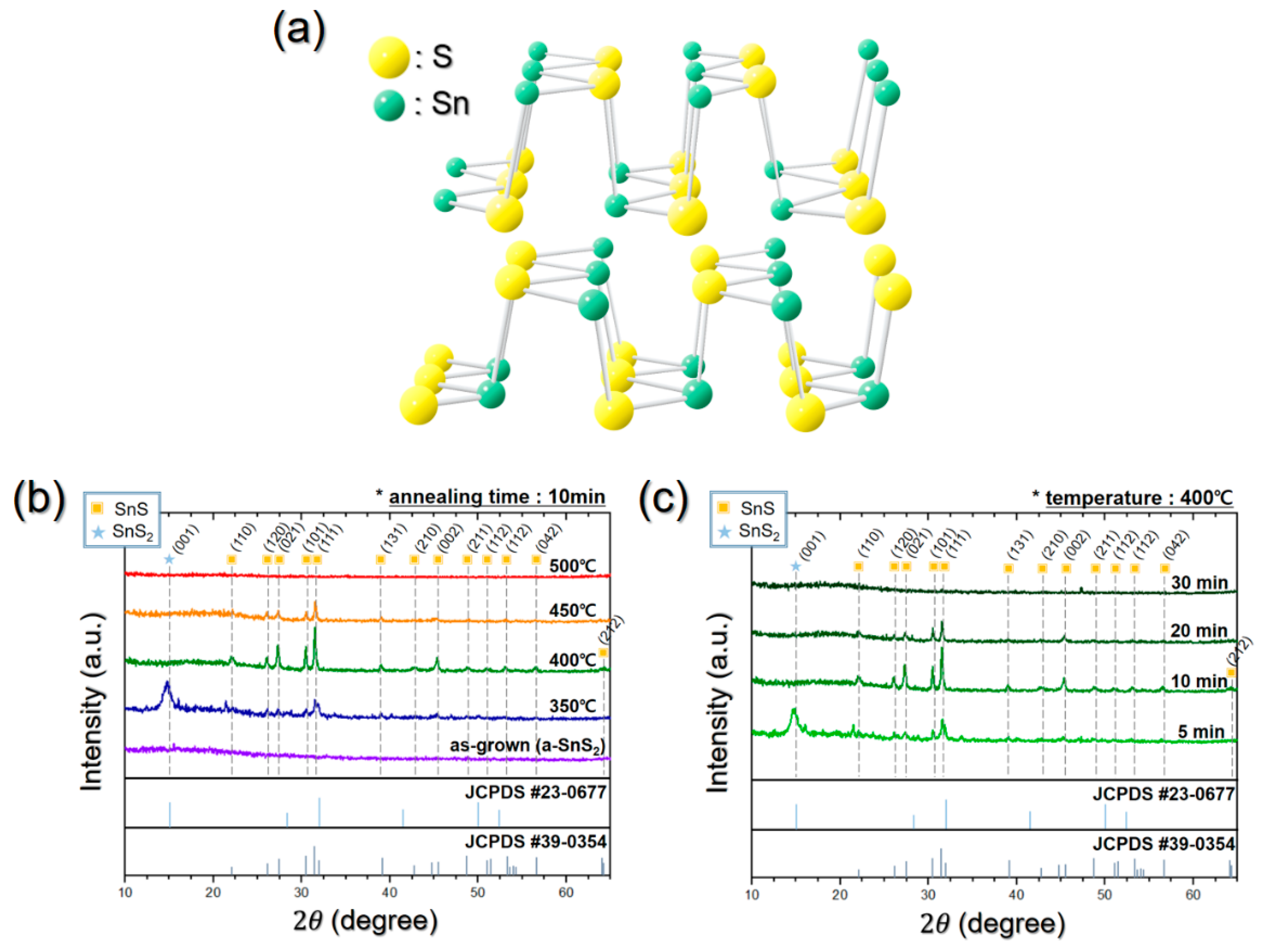
Figure 1. (a) Structure of the orthorhombic SnS crystal. X-ray diffraction (XRD) patterns of vacuum-annealed amorphous SnS2 (a-SnS2) film (b) with various temperatures for 10 min and (c) various time conditions at 400 °C.
Applsci 09 04606 g001
Figure 2. X-ray photoelectron spectroscopy (XPS) spectra of a-SnS2 film and SnS film transformed from a-SnS2, indicating (a) Sn 3d and (b) S 2p peaks.
Applsci 09 04606 g002
Figure 3. Optical properties of a-SnS2 film and the SnS film: (a) absorption coefficient in the visible region and (b) (αhν)2 plot to determine the optical bandgap.
Applsci 09 04606 g003
Figure 4. (a) Schematic image of a showerhead-type atomic layer deposition (ALD) chamber used in this study. (b) SEM images of 16 points on four-inch scale wafer for uniformity testing of the SnS film process.
Applsci 09 04606 g004
Figure 5. (a) Schematic diagram of the SnS film process sequence with a seed layer. (b) XRD patterns of seed layers and vacuum annealing result of seed layers. (c) XRD patterns of the SnS films with various seed layers. (df) SEM images of SnS films obtained by annealing a-SnS2 films, including various seed layers, at vacuum atmosphere.
Applsci 09 04606 g005
Figure 6. (a) Water contact angle analysis of SiO2 substrate and seed layers. (b) Grain growth behavior of SnS films at the interface with SiO2 substrate and seed layers.
Applsci 09 04606 g006
Table 1. Sn 3d and S 2p peaks of the XPS spectra in comparison with the reference.
<Ref *> (eV)
Sn 3d5/2S 2p3/2Spacing (Sn 3d5/2 − S 2p3/2)
SnS2486.5161.6324.9
SnS485.7161.0324.7
<obtained data>
Sn 3d5/2S 2p3/2Spacing (Sn 3d5/2 − S 2p3/2)
SnS2486.4161.6324.8
SnS485.8161.2324.6
* by Price et al. [1].
Table 2. Calculated crystallite size for each {hkl} plane of SnS films using various seed layers.
SampleA (No Seed)B (Using SnS Seed)C (Using SnS2 Seed)
2θ (deg)/hklCrystallite size (nm)
27.47/02135.8-49.1
30.47/10141.5-45.2
31.53/11153.225.056.4
39.04/131--37.6
45.49/00226.5-34.6
Table 3. Electrical properties of SnS films using various seed layers by the Hall effect measurement.
SampleA (No Seed)B (Using SnS Seed)C (Using SnS2 Seed)
Bulk concentration (cm−3)2.24 × 10191.32 × 10193.90 × 1019
Resistivity (Ωm)4.96 × 10−26.67 × 10−25.13 × 10⁻²
Mobility (cm2/Vs)32.6711.508.97