1. Introduction
The problems associated with food production due to the growing population, changing climate, reduced ground water resources, and increased transportation costs could be solved using concepts such as vertical farming [
1], urban agriculture, and plant factories with artificial lights (PFAL) [
2]. These modern food production techniques prove to be effective in increasing the biomass throughput per volume of water used per growing area, in comparison to the conventional farming techniques. These methods however, require a significant amount of energy for generating the artificial micro-climate necessary for the plants growing in them [
3].
Several studies have been undertaken to evaluate the economic feasibility of a typical vertical farm and how these farms could be made profitable by combining different organisms (e.g., plants and fishes) and exploiting the symbiotic behavior between them. Such investigations are noticeable in the area of space research and exploration projects for designing bio-regenerative life-support systems: MELiSSA (Micro-Ecological Life Support System Alternative) [
4], ACLS (Advanced Closed Loop System) [
5], CELSS (Controlled Ecological Life Support System) [
6], and CAB (Controllo Ambientale Biorigenerativo) [
7]. Improved biomass output was shown when plants and mushrooms are grown in symbiosis [
8]. Studies performed on farms with plant–fish integrated production have also shown reduced operation cost [
9]. The economic feasibility analysis of the vertical farm performed by the German Aerospace Center DLR has shown that, on combining production of different organisms, the overall cost in such farms are reduced [
10]. Quantification of mass and resource fluxes between organisms is important for performing simulation studies, designing experiments, and developing automation and farm infrastructure. CUBES Circle is another project, funded by the German Federal Ministry of Education and Research, aiming on the study of mass and energy fluxes among plants, fishes, and insects connected together [
11].
The above discussed works highlight some of the research potential and shortfalls in the area of optimized food production in controlled and connected environments. This requires, firstly, a quantitative study of growth processes of individual organisms and its environmental factors; secondly, study of resource fluxes and symbiosis between organisms and its environment; and, finally, development of mathematical models that adequately describe them.
The fundamental step of such studies is the development of a controlled environment suitable for different organisms. Plants (
Lactuca sativa and
Ocimum basilicum), fungi (
Agaricus bisporus,
Lentinula edodes, etc.), and insect larvae (
Hermetia illucens and
Tenebrio molitor) are some of the candidates considered for developing the controlled environment proposed in this work. A preliminary analysis of the requirements for developing such system highlights the need for a sophisticated setup with actuators to generate the necessary micro-climate, sensors to measure various variables (e.g., O
, CO
, humidity, etc.), and interface to exchange resources (e.g., water, air, and nutrients). Some modern commercial growth chambers support CO
concentration regulation and inlet for additional sensors through instrument port, but infrastructure for resource exchange and test automation is either limited or non-existent [
12]. Modification of these growth chambers for incorporating necessary infrastructure is theoretically possible but adds to the cost and complexity. The literature [
13,
14] also indicates the need for custom devices irrespective of the availability of commercial growth chambers for studying and phenotyping biological organisms. This is primarily due to a very high equipment cost (>6000 EUR for growth chamber and additional cost for control software), proprietary hardware/software, and requirements very specific to the nature of studies performed.
This work uses some of the concepts proposed in the literature and proposes novel ideas and modifications to develop a low cost system suitable for previously mentioned studies. The following are some of the design requirements considered and realized:
Actuators for air conditioning, light spectrum adjustment, and on-demand water and gas exchange with airtight containment
Measurement system for air quality, gas concentrations, air pressure, air and substrate temperatures, humidity, and substrate moisture
Modular design using off-the-shelf components and 3D printable parts
Software framework for experiment regime design and execution, user interaction, and data collection and analysis
In the following sections, firstly, hardware component selection and electronic interface design are explained followed by software component design and integration of an example control regime. The results of sensor–actuator tests for performance evaluation of the designed system are then presented. Finally, the results of experiments executed for the study of growth of biological organisms are discussed.
2. Material and Methods
The rearing process of biological organism such as plants, fungi, and insects have special requirements with respect to climate, nutrient supply, and gas concentrations. This section describes in detail how these special requirements were translated into design choices using off-the-shelf hardware components, 3D-Printable custom parts, and open-source software. All design files, source code, and supporting documentation used in this work are available on-demand for reproduction and further development.
2.1. Hardware Design
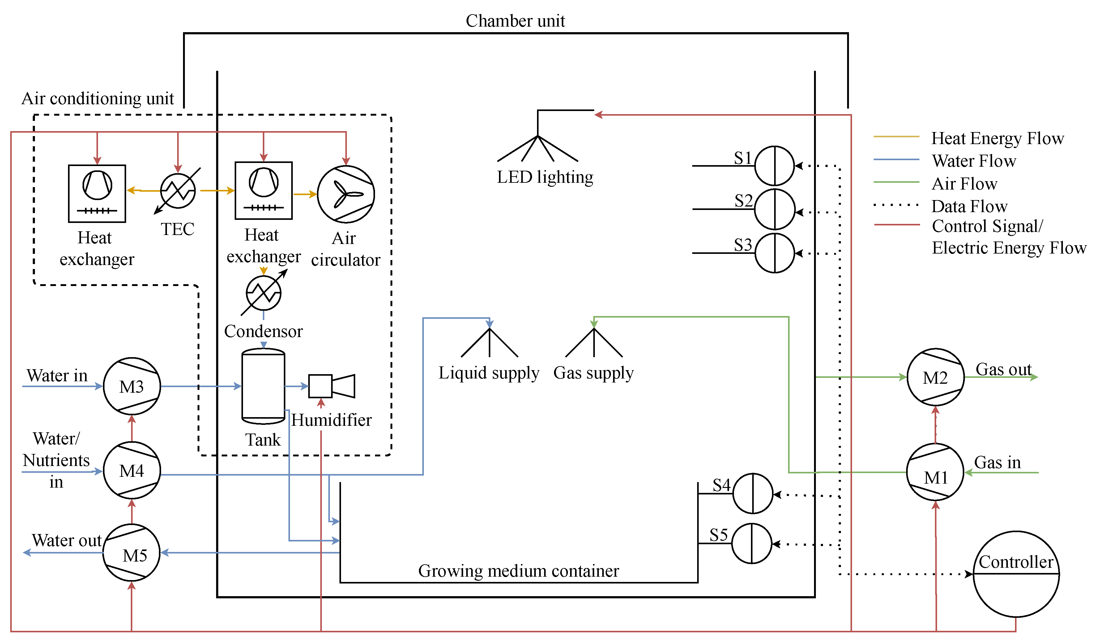
A process model of a controlled environment (growth chamber), as shown in
Figure 1, was drafted based on the functional requirements. The central chamber unit is where the organism of interest is reared and studied. This part, being the fundamental component of this process model, was selected first. A polypropylene container of 75
volume with airtight sealable lid was selected. This volume was constrained due to the choice of an off-the-shelf container, which also corresponds to the volume of low- to mid-tier commercial growth chamber. Based on this chosen volume, specification of other modules (e.g., heater, cooler, and pumps) were derived. Modifications to the chamber to obtain desired functionalities are explained in the following sections.
2.1.1. Air Conditioning
The temperature of the growing chamber in which subjects grow influences various metabolic processes as well as triggers certain biological events. In the case of
Lentinula edodes fungi, fruiting is triggered by a temperature drop [
15]. Similarly, in the case of plants, biological processes, such as photosynthesis and even onset of anthesis is affected by temperature [
16]. Humidity also influences the metabolic activities of both the subject and unwanted fungus. Humid environment with sufficiently warm temperature provides suitable platform for organisms such as unwanted fungus to thrive and possibly suppress or destroy the growth of the subject [
17]. Therefore, it is important to condition the air inside the chamber.
Application of compact ceramic heating elements for heating air can be seen widely in industrial and home appliances [
18,
19]. However, cooling the air requires sophisticated mechanical parts and increases size and cost. Some research works [
20,
21] showcase the application of thermoelectric cooler (TEC) module for heating, cooling, and de-humidification.
Humidification on the contrary can be achieved by accelerating the evaporation of water. Despite the transpiration contributed by metabolic activities of the subject growing in the chamber, it requires long duration to reach desired humidity and is uncontrolled. To compensate for this shortcoming, the humidification process is controllably accelerated using an ultrasonic atomizer that breaks water into fine particles [
22]. These technologies were combined together to implement the air conditioning system.
Construction
A combination of TEC module of varying cooling capacities ( 36
, 75
, and 126
) were tested with heat exchanging components of different sizes for both hot and cold side. A 126
module with peak current and voltage of
and
, respectively, was selected for highest performance. The side of the TEC module facing the inner side of the chamber is interfaced with an aluminium passive heat exchanger while the opposite side with an active water cooled heat exchanger. A combination of two PC-cooling fans are used in push–pull arrangement to actively cool the otherwise passive heat exchanger and also to introduce air circulation inside the chamber unit. This design choice of non-similar heat exchanger is made to improve the cooling/heating performance while maximizing the inner volume of the chamber unit. In cooling mode of operation, the inner heat exchanger condenses water, which is accumulated in a reservoir. An ultrasonic atomizer is integrated into the reservoir using the water stored in it for humidification. The enclosure is a custom designed 3D printed part with an integrated reservoir and encapsulates the passive heat exchanger, air circulation fans, and humidifier. These parts, as depicted within dashed box in
Figure 1, constitutes the air conditioning unit.
TEC Driver
Operation of a TEC module for both heating and cooling requires the infrastructure for changing the magnitude and polarity of the voltage applied across it. Change of voltage polarity can be achieved using an H-bridge circuit but magnitude variation requires additional circuitry. This driver circuit, as shown in
Figure 2, can be constructed using two half bridge BTN8982 device and a low-pass L-C filter [
23]. This combination enables the change of current flow direction through the TEC, thus changing its operation mode. Using PWM signals to operate the driver in ON–OFF mode enables the control of current flowing through the device. However, the power loss in TEC module in such a configuration is higher than in the DC mode. To compensate this power loss, a low-pass L-C filter circuit with a cut-off frequency
equal to
is implemented between the TEC and the H-bridge driver. A signal with PWM frequency of 64
is generated from the microcontroller such that the voltage ripples are minimized by the filter circuit, resulting in a smooth DC voltage. Using this setup, the voltage across the TEC can be regulated from 0
to a 12
maximum by varying the pulse width from 0% to 100%.
2.1.2. Gases, Water and Nutrient Exchange
The primary raw product and byproducts of the biological processes constitute O, CO, and HO (liquid and vapor). Concentration measurement of these compounds in gaseous forms is necessary for quantitative study of the mass fluxes due to the underlying biological processes. This requires measurements to be performed in sealed chamber. Simultaneously, to enable normal growth, these concentrations must be regulated. Adding to the complexity, water and nutrient supply mechanisms for the subjects vary with some requiring overhead spray (fungi) and some through a water bath. These requirements pose a challenge to design the infrastructure that provides both air-tight containment and fluid exchange on demand. To overcome this limitation, a circulation unit constituting five membrane pumps (M1–M5) is used for fluid circulation into and out of the chamber. These pumps enable the circulation on demand while keeping the chamber air-tight. Pumps M1 and M2 are coupled to work in opposite flow directions such that Pump M1 removes the gas mixture from the chamber to the external sink and Pump M2 fills it with gases of known concentrations from an external source. The circulation unit uses Pumps M3–M5 for water and nutrient supply, where Pump M3 supplies water to internal reservoir and eventually to growing medium container on overflow, Pump M4 supplies water and nutrient mixture to spray nozzle or directly to growing medium container, and Pump M5 removes water to external reservoir where water could be recycled or enriched with nutrients as required, thus completing the water and gas circulation between chamber and the external source.
2.1.3. Lighting
The radiant flux required for the subjects of interest varies between species and organisms. Certain fungal species require white light while plant species mostly require red and blue components [
24]. The literature also indicates the changes in chemical composition in plants in response to red and far-red light [
25,
26]. Events such as flowering and germination could be triggered by varying the spectral components and circadian rhythms [
27,
28]. This, therefore, requires light source with adjustable spectral composition and power. Narrow-band LEDs covering a wide range of wavelengths and wide-band white LEDs, as shown in
Figure 3, are widely available from different manufacturers [
29].
One of the goals of this work was to design and include a light source with adjustable spectrum. Spectral power distribution of typical white LEDs with different color temperature (3000–6500 ) could be used as the primary source and the additional wavelengths that influences various biological processes or trigger events could be included using narrow-band LEDs. A complete range of spectral requirements for various species is still unknown and needs to be studied. A preliminary LED lighting unit with a combination of neutral white, narrow-band red, blue, green, and support for inclusion of UV/far-blue and IR/far-red LEDs was designed.
LED Driver for Spectrum Regulation
Spectrum adjustment and light-based event triggering require that the individual channels (i.e., white, red, blue, green, UV/far-blue, and IR/far-red) be independently adjusted. LEDs used in this system are daisy-chained modules of three or four LEDs connected in series and operating at 12
. As shown in
Figure 4, every color channel has a MOSFET based low-side driver to adjust the radiant spectral power using PWM signals. These vertical columns of daisy-chained modules are combined into groups that are operated using relays. This grouping is done such that the first group corresponds to the central vertical column and the preceding groups correspond to the adjacent columns. The overall advantage of this setup is that the radiant spectral power and the total area covered by the LEDs can be varied as required.
2.1.4. Sensors
Thecombination of Sensors S1–S5, listed in
Table 1, are capable of measuring CO
, O
, and volatile organic compound (VOC) concentrations; air and substrate temperatures; atmospheric pressure; relative humidity; and moisture of growing medium. Sensor S1 is a non-dispersive infrared sensor for CO
concentration measurement also housing an additional relative humidity and temperature sensing element. Sensor S2 is an environmental sensor for measuring relative humidity, temperature, pressure, and VOC concentration. The O
sensor (Sensor S3) is an electro-chemical galvanic cell that produces voltage on exposure to O
. Its sensitivity is proportional to the O
concentration but its analog output is out of range of the internal ADC of the microcontroller and thus an external ADC with programmable gain is used for signal amplification. All the above mentioned sensors use I2C communication interface to transfer measurement data to the microcontroller and is enclosed as a stand-alone sensor unit.
Temperature sensor (Sensor S4) is used for substrate temperature measurement and communicates with the controller using a proprietary one-wire interface. This interface allows addition of several sensors to the same data-bus without additional hardware changes. The substrate moisture concentration is measured using a capacitive sensor (Sensor S5) with analog voltage output. These two sensors are separated from the other sensors to facilitate their placement inside the substrate or the growing medium.
2.1.5. Control Unit
The control unit, as shown in
Figure 5, constitutes the microcontroller, drivers, switching circuits, voltage regulation, and current protection circuits. The microcontroller used is a 32-bit ARM Cortex M4 device from ST-Microelectronics clocked at 100
. It is connected to a SD card for local data logging and storing configurations and calibration data. A real-time clock (RTC) is used for time keeping and timestamps for logged data. Communication to external system is realized using UART to USB interface. The PWM peripheral pins drives the LED lighting system, TEC heating-cooling system, internal circulation fans, and external heat exchanger fan. General purpose input–output drives the electromechanical relays of the LED group switch and Pumps M1–M5. The entire system is designed to be operated using a single 12
DC source and thus incorporates the necessary DC-DC step-down converter for supplying 5
for low voltage electronic components (microcontroller, humidifier, etc.).
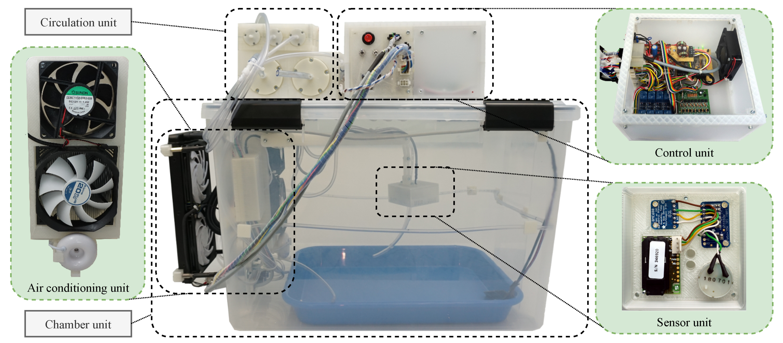
2.1.6. Assembled System
Components constituting the modular units were assembled together with 3D printed parts and enclosures, as shown in
Figure 6. The control unit enclosure is made of a 3D printed frame and acrylic walls with Molex connectors for connecting it with the chamber unit. The sensor unit is suspended inside the chamber unit with a 3D printed adjustable arm. The circulation unit is connected with the bulkhead connectors of the chamber unit using 4
polyvinyl chloride tubes, keeping the chamber unit air tight. The LED panel, not visible in the figure, is mounted on the inner side of the chamber lid and connected using a Molex connector to enable complete disconnection while opening the lid. Push–pull arrangement of the fans and the integrated humidifier can be seen in the highlighted air conditioning unit in
Figure 6.
2.2. Software Design
Similar to the modular approach of the hardware design, software components were also developed as independent components and integrated using standard interfaces. To enable autonomous operation of the chamber and machine-to-machine (M2M) communication, the following requirements were established and realized:
Design and execution of control application or custom experiment regimes on the designed system
Access to measurement data and system states for performing data analytics, monitoring, and process control
Interface to specify optimal operation points (set-points) and control parameters computed externally (expert user or decision support system)
These requirements were translated to a framework, as shown in
Figure 7, with a three part solution: (1) open-source firmware core for control unit with necessary drivers, middleware and application interface for reliable operation of the chamber; (2) cloud platform with data, protocol and web sever for data aggregation. data visualization. and interaction with chambers for process control; and (3) code generation framework for control application or experiment regime development. This architecture facilitates the use of the controlled environment for different subjects and executing different experiments. The following sections explain the software design of the IoT Framework and device firmware in detail.
2.2.1. Device Firmware
The firmware core, running on the microcontroller, is categorized into four layers to provide abstraction, as shown in
Figure 8. The hardware abstraction layer is dependent on the microcontroller and is based on the Arduino libraries (arduino core) ported for STM-32 microcontrollers (STM32duino). The device manager layer contains managers, implemented as state machines, specific to each electronic component connected (e.g., sensors and actuators). These managers are responsible for: data access from sensors, driving the actuators, monitoring for faults, scheduling the measurements at specified intervals, intercepting external communication, and logging data. The middleware layer contains managers, which serve as brokers that direct the flow of data between the modules of different layers. Data from the sensors are accessed by the modules of different layers using a data structure managed by data manager. The message broker directs the function calls and data between the external system (e.g., decision support system or user) and the corresponding manager modules. The system manager checks if all other managers are running, periodically servicing the watchdog timer, and re-initializing their state machines in the case of error. The task scheduler implemented is preemptive priority based, with highest priority assigned to the components of device manager layer and lower priority to the layers above it. The application interface translates control decisions made by the application layer into suitable actuator commands, thus abstracting the application logic from the hardware. The application layer contains the experiment regimes or apps (e.g., climate control, respiration test, etc.) that are custom developed. This abstraction provides the system its programmability aspect that enables users to develop these regimes and execute them without having to deal with the underlying hardware and firmware.
2.2.2. Application Development
Application development requires the knowledge of C/C++ programming language since it involves the modification to the application layer in the firmware. When the experiments performed with the chamber differ, the application that runs on the control unit must be changed accordingly. This requires firmware modification and might not be feasible for all end users. To compensate this limitation, an additional development framework based on MATLAB/Simulink was developed to utilize the model-driven-development environment to create the experiment regimes (apps). This framework provides a Simulink interface model within which the application can be designed. Based on the designed Simulink model, this framework generates the application interface of the firmware and integrates the embedded code generated from the Simulink model into firmware core, as indicated in
Figure 7. This framework also generates an application user interface that can be directly imported into the web interface of cloud platform. This is done using a developed MATLAB script that generates HTML code snippets for every input signals defined in the Simulink bus objects of the model. These code snippets are combined into standard user interface element (widget) for every bus object that can be used within the proposed cloud platform. This eliminates the need to develop user interfaces for accessing process variables and thus saves time. However, in the absence of MATLAB/Simulink, application can be developed using C/C++ IDE tools (e.g., Arduino) and the corresponding UI has to be manually configured in the cloud framework.
2.2.3. Cloud Framework
Monitoring of data in real-time and performing computation based on the measured values are crucial. It is also necessary to scale the number of devices that can be simultaneously operated. Suitability of ThingsBoard, an open-source software, as a candidate for implementing the cloud platform can be justified by its use in several research work in the internet of things (IoT) domain [
30,
31,
32]. This platform includes a database server for data storage and retrieval; a web server for providing web-clients through which data and settings could be accessed or changed; and a protocol server (e.g., MQTT, HTTP) for enabling communication with end devices.
As a proof of concept, ThingsBoard was set up on a virtual machine and configured to aggregate data from multiple device instances. Interaction with the connected chamber is enabled through three configured dashboards (monitor, diagnose, and control) with the possibility to import additional widgets (user-interface/UI elements), as shown in
Figure 9. Monitor dashboard displays various measured and system parameters in real-time. Diagnosis dashboard allows manual control of actuators and also provides command line interface for debugging the designed system. Control dashboard, containing widgets generated by the application development framework, is application specific and allows the configuration of its parameters (e.g., set-points, control parameters, etc.).
2.2.4. Data Exchange
Data between the server and the designed control unit are of four different types: telemetry data from the control unit to server; RPC (Remote Procedure Call) requests from server to control unit; RPC response from the control unit to server; and attributes (set-points, configs, etc.) from server to the control unit. These four types of messages are defined as three MQTT (Message Queuing Telemetry Transport) topics (i.e., telemetry, attributes, and RPC) in the server. The payload of these topics ia a JSON (JavaScript Object Notation) string that encapsulates the key-value pair (Listing 1). This key-value pair for telemetry and attributes are simply the parameter that is measured and its value, whereas, for RPC, there are only two key-value pairs, of which the first corresponds to the name of the method to be called and the second corresponds to the parameters that need to be passed to the method.
| Listing 1: MQTT Payload formats |
| # Telemetry and Attributes |
| {"T":21.65, "CO2":650, "ventilatorState":false, ...} |
| # RPC |
| {"method":"setTemperature", "param":"25"} |
| # RPC Extended |
| {"method":"setSetpoints", "param":"{"T_Min":20,"T_Max":25,...}"} |
Communication between the chamber and the server is realized using an external device indicated as MQTT Streamer in
Figure 7. It forwards the JSON data received from the control units over USB to the server, after encapsulating the message into a MQTT broadcast messages. The RPC calls from the server is decoded into JSON string and is forwarded to the respective control unit over USB. This forms the bridge between the standalone control unit and the server.
2.2.5. Climate Control Application
A set of open loop and closed loop controllers, as shown in
Figure 10, were implemented in Simulink using the application development framework. These constitute PID controller for temperature control; hysteresis controller for humidification and CO
concentration; circadian generator for LED light spectrum; and an additional cyclic controller for CO
concentration.
Circadian Rhythm Generator
The chamber does not include sensors for measuring the radiant flux. Therefore, any disturbance in this flux due to external source cannot be measured and is not compensated. If this disturbance is avoided, the light spectrum, and thus the spectral power, inside the chamber can be individually varied and the necessary radiant flux can be achieved. To achieve this, a configurable open-loop controller for circadian rhythm generation was designed. This uses a sinusoidal function to generate the base ON amplitude signal
where
,
, and
are the ON, OFF, and offset times in seconds (
). Using the given set-points for minimum and maximum percentage radiation power, the input for individual LED channels are generated as
where
and
are the minimum and maximum spectral power in percentage (%) of the
ith LED color channel and
, 6 corresponds to white, red, green, blue, far-red, and far-blue, respectively.
4. Conclusions
The design of a programmable controlled environment using off-the-shelf components, custom designed 3D printed parts, and open-source and self developed software was possible. Actuators for resource exchange, climate control, and light spectrum adjustment were designed, incorporated, and tested. Software framework was developed and tested for programming experiments and logging sensor data and system states. This framework also enabled access to logged data, adjusting controller parameters, and performing diagnostics through a graphical interface both locally and remotely. Example applications were developed using the application development framework to showcase the capability of the system to execute custom control algorithms and experiment procedures for automated study and information capture. Hardware and software were designed with focus on modularity and scalability, respectively, allowing integration of additional hardware components (sensors and actuators) and connecting multiple devices to the cloud framework. Results of the actuator and sensor tests revealed their capabilities, limitation, and also improvement areas such as chamber insulation for better thermal performance. These results also indicated that Sensors S1–S4 performed well in measuring the required parameters while Sensor S5 could be replaced for a more robust moisture sensor when available. Experiments performed with plants and larvae generated data that can be used to perform quantitative studies on the biomass and byproduct production. These experiments also provided data that can help study growth processes and their responses to the environmental factors.
The designed system fulfills the requirements of a controlled environment that is programmable, low-cost (<1000 EUR), open-source based, and suitable for small plants, insect larvae, and mushrooms. The results obtained and presented in this work serve as fundamental setup for the detailed study of individual subjects and development of mathematical models, which shall be the focus of future work.


