Featured Application
The proposed new method can be used to maximize the transfer efficiency of mid-range wireless power transfer systems.
Abstract
Wireless power transfer (WPT) using magnetic resonant coupling technology, came into focus promptly by virtue of its long transfer distance, and its non-radiative and high-efficiency power transfer. The impedance matching has been studied in the literature in recent years. However, there is no suitable way to reach the optimum load in reality. In this paper, a new method is proposed to maximize the power transfer ability of a given pair of coupled coils. An analytical calculation of the mutual inductance is presented accurately with respect to the angled concentric multiple-turn printed spiral coils (PSC). In addition, the experimental results were in good agreement with the circuit simulation. Finally, a WPT experiment setup working at 3MHz resonance was established. The experiment results verified that the maximum transfer efficiency at fixed distances can be easily achieved by adjusting the angle to reach impedance matching. Compared to prior to optimization, the maximum improved efficiency was improved by 11%.
1. Introduction
Wireless power transfer (WPT) based on the magnetic resonance was reported by Nicola Tesla a century ago. In 2007, the strongly coupled magnetic resonances in magnetically-coupled WPT was proposed by researchers from Massachusetts Institute of Technology (MIT) [1]. Due to its convenience, high efficiency and other advantages, WPT technology is widely used in various practical applications, such as industry [2,3,4,5], medicine [6,7,8] and commercial portable equipment [9,10]. In recent years, it has been found that the basic analysis of WPT technology, mainly coupling mode theory (CMT) [1] and circuit theory (CT) [11] need to be optimized further. For an electrical engineer, the analysis method based on CT is simpler and more precise compared to that based on CMT, thus the CT method has been adopted extensively. With in-depth study of the MCR-WPT technology, many problems such as frequency splitting, impedance matching, enhance transfer efficiency and system stability have risen [12,13,14,15], especially with regard to transfer efficiency, which decreases sharply with the increases in transmission distance. This seriously hinders the development of WPT technology.
In order to achieve high-efficiency transfer in WPT systems, most previous work has concentrated on two aspects: (1) maintaining high transfer efficiency when transmission distance changes; and (2) maximizing transfer efficiency when transmission distance is fixed. The former is mainly accounted for by increasing the strength of the coil coupling or improving the quality factor of resonant coils, which is actually difficult to achieve in actual application contexts. In addition, due to the limitations of current technology, the quality factor of resonant coils has reached a bottleneck. Takehiro Imura et al. [16] illustrated that the maximum transfer efficiency could be achieved by adjusting the distance between the resonant coils. The experimental results showed that the transfer efficiency of the system remained unchanged within the critical distance range, but decreased sharply when the critical value was exceeded. Wang-Sang Lee et al. [17] elaborated on an ingenious coil structure design that prevented the coupling coefficient between coils from decreasing dramatically with an increase in distance. In [18,19], metamaterials and intermediate resonators were used to enhance the transfer efficiency by increasing the strength of coil coupling, as a result, the analysis of the system becomes more complicated. On the other hand, the purpose was to maximize the transfer efficiency of the given resonant coils, and impedance matching is the main way to achieve the maximum transfer efficiency. In reference [20,21], the impedance matching was achieved by changing the distance between the resonant coil and the load coil. However, larger spaces will be occupied due to the introduction of distance regulation, and the change of horizontal distance is difficult to realize in engineering. By using additional circuits containing inductive and capacitive components, impedance matching can be achieved easily [22]. The circuit topology will be more complex and controlling the additional circuit is also difficult. In [23], impedance matching was acquired by controlling the duty ratio of the switching tube of the DC–DC converter circuit. However, additional losses were introduced and switching tubes are also complicated to control.
In this paper, a novel method for impedance matching in the four-coil WPT system was proposed. Firstly, the equivalent circuit of the four-coil WPT system was expounded to obtain the optimal relation between electrical parameters. Furthermore, the relationship between the transfer efficiency represented by the scattering parameters and that represented by traditional circuits was also deduced. Then, the theoretical calculation of the coil self-inductance and mutual inductance of the experimental device in this paper was derived. The accuracy of the theoretical calculation was verified by modeling and running a simulation on Ansys Maxwell 16.0. Finally, an experimental setup was built to verify the proposed method in this paper. The method can be used to change the angle of concentric printed spiral coils to simply achieve the optimal impedance matching. This method also ensures the maximum efficiency of a given pair of resonant coils is achieved at different distances. The measured transfer efficiency of the WPT system was improved by 11% compared to before optimization.
2. Circuit Theory Analyzing
Figure 1 shows the simplified circuit model of the four-coil WPT system. It is composed of four coils: Drive loop, transmitting (Tx) coil, reserving (Rx) coil, and load loop. Each of these can be equivalent to lumped circuit elements (L, C, and R) in series. Ri Ci and Li (i = 1, 2, 3, 4) are equivalent to the internal resistance, compensation capacitor and self-inductance of the coils, respectively. The drive loop is excited by a source VS with output impedance RS. RL represents the pure resistance load linked to the load loop. Mij is the mutual inductance of i coil and j coil (i, j = 1, 2, 3, 4, i ≠ j). To simplify the analysis and calculation, the cross mutual inductance (M13, M14 and M24) is neglected. Kij is the coupling coefficient between two adjacent coils. The coupling coefficient is related to the mutual inductance as follows.

Figure 1.
Equivalent circuit model of the four-coil WPT system.
Based on mutual coupling theory and the Kirchhoff voltage law (KVL), the matrix equation of the four-coil WPT system can be derived as
where Ii is the current of each loop of coils, ω is the angular frequency of the operating WPT system, ω = 2πf, showed in Figure 1. Z11, Z22, Z33 and Z44 are subject to the following relations.
To further simplify the analysis, Z12, Z23, and Z34 are defined as follows. Z12 is the reflect impedance from load loop to Rx coil. Z23 is the reflect impedance from Rx coil to Tx coil. Z34 is the reflect impedance from Rx coil to driven loop.
Substituting (3) and (4) into (2), the currents in the drive loop and the load loop can be expressed as
According to the traditional expression of electrical transfer efficiency, η, the efficiency of which is equal to the ratio of the effective power load Pload and the input power Pin. It is calculated as follows.
Also from [24], the squared magnitude of S21 is simply the ratio of delivered output power to maximum available source power, which can be expressed as follows:
where the load RL is equal to the equivalent internal resistance of the source RS. In order to achieve the resonance condition, the operating frequency f0 of the system will be guaranteed to be the same as the resonance frequency fi of the coils. Moreover, the input impedance Zin is approximately equal to Z12 because R1 is very small. For the characterization of the scattering parameters, the prerequisite is to ensure that the maximum power output, that is, Z12 matches the internal resistance of the source. Then, the square of |S21| is equal to two times of η, as in Figure 2c,d. In terms of the traditional electric, aimed at gaining maximum transfer efficiency, we can make Z12 large enough by adjusting the relevant parameters, as shown in Figure 2a, so that the modulus of Z12/(Z12 + Z11) is close to one. At this time, η will be close to |S21|2 according to Figure 2b,d. Thus, |S21|2 can be regarded as the maximum transfer efficiency that the system may achieve. In the following analysis and experiment, |S21|2 will be used as the main analysis parameter of the system. A detailed description of the simulated parameters is listed in Table 1.
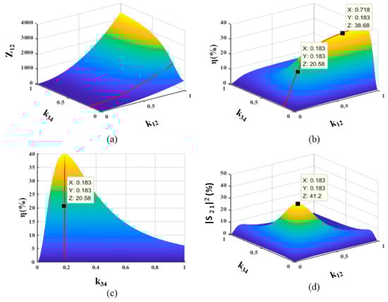
Figure 2.
Numerical analysis results of the four coil system, (a) Z12 versus k12 and k34, (b) transfer efficiency versus k12 and k34, (c) is the y-z view of (b,d) |S21|2 versus k12 and k34.

Table 1.
Simulated parameters of the proposed four-coil structure.
Based on the matching conditions of the scattering parameters, RS, RL and Zin are equal. Equation (7) can be simplified as follows:
The four-coil WPT system can be equivalent to a two-coil system, as shown in Figure 3. The drive coil is equivalent to the voltage source, and the load coil is represented as Z34. According to the previous literature [16], in order to obtain the maximum S21, the derivative of Expression (8) with respect to Z34 is taken, and then the derivative result is set to zero. The optimal Z34 which maximizes S21 can be gained and the optimal k34-opt will also be attained by transformation. At the same time, k34-opt is substituted into the expression of Z12, and the optimal k12-opt can also be attained.
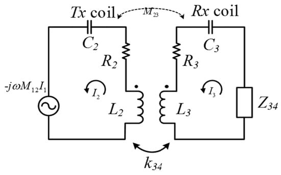
Figure 3.
Simplified circuit model of the four-coil WPT system.
As shown in Figure 2b,c, the red line denotes the transfer efficiency when k34 is fixed and consistent with the calculation result of Equation (9). It is worth mentioning the complete symmetry four-coil WPT system when the transmission distance is fixed, existing the same k12 and k34 values, that maximize the transfer efficiency. This result is consistent with Expression (9), and it is also confirmed by the simulation, as shown in Figure 2d. Finally, k23 is a constant value, which means that the transmission distance is fixed, k34 is a variable to achieve the optimal load, and k12 can be changed to match the internal resistance of the source in the simulation. Thus we found that the impedance matching of the overall system is necessary to achieve the maximum transfer efficiency.
3. Calculating Couple Coil Parameters
In this paper, a novel method has been proposed to calculate the self and mutual inductance of multiple-turn printed spiral coils (PSC), as shown in Figure 4a. The PSC is a square coil with a rectangular cross-section. As described in [25], the PSC can be equivalent to a set of concentric and coplanar single-turn coils, connected in series, as shown in Figure 4b. The error under this assumption can be neglected. Moreover, the computed results were verified using the finite simulation software Ansys Maxwell 16.0.
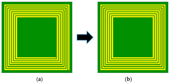
Figure 4.
Equivalent model of printed spiral coils: (a) physical truth, (b) equivalent mode.
In [26], many formulas and tables used to calculate the self-inductance and mutual inductance of various cross-sections and shape conductors were presented, but it is not apparent that the listed expressions can be directly applied to the PSC in this paper. Combining [26] with the coil model in this paper produced an expression that exhibits a good approximation for the self-inductance of a one-turn inductor in air:
where μ0 is the permeability of the vacuum, a is the length of the side of one turn coil, and b, c are the width and thickness of rectangular cross-section copper conductors.
According to superposition theorem, the self-inductance value of the PSC can be viewed as the sum of the self-inductance of the single-turn coils and the mutual inductance between two non-adjacent coils. The general self-inductance of the PSC can be written as:
where Li-self is the self-inductance of the ith turn of an inductor with N turns. Mij is the mutual inductance between the ith turn and the jth turn of the square spiral coils, and i is not equal to j. The mutual inductance of two parallel coaxials can be obtained by summing the mutual inductance between two turns. The structure diagram is shown in Figure 5a. In this WPT system, the impedance matching is achieved by varying the angle of the inner coils, therefore, the mutual inductance of two coils in different planes is a key factor in the paper. A sketch of two non-plane coils is presented in Figure 5b.
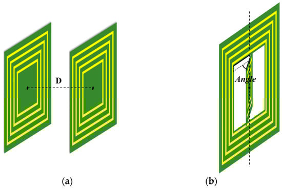
Figure 5.
Relative position relation of coils, (a) parallel coaxial coils, (b) concentric coils.
It is crucial to calculate the mutual inductance of single-turn coils. When analyzing the proposed position relation of coils, every turn of coils can be deemed as connecting with four line segments. The segments of different coils have three position relations: parallel, vertical or non-coplanar. According to the Neumann formula (12), which represents the mutual inductance of two line segments, we found that the mutual inductance of vertical line segments is zero. Therefore, the position relation of the line segments can be expressed as disjointed while considering the mutual inductance.
Figure 6a shows two non-intersecting lines in space, two planes θ1 and θ2 where the prescribed lines inside them can always be found. a and b are the length of these lines, and the inclined angle of the presented lines is φ in the range of 0 ≤ φ ≤ π. The vertical distance between the two planes is h. x and y are the coordinate axis and the orientation consistent with the current direction of wires, respectively. O1 and O2 are original points of the coordinate axis, and x1, x2, y1 and y2 are the beginning and end terminals of the lines, respectively.
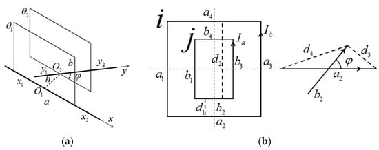
Figure 6.
(a) General line segment position relation; (b) Diagrammatic drawing of single-turn coils.
From (12), we obtain the calculation formula for the mutual inductance of two general line segments, which can be written as:
where D11, D12, D21, D22 are the distance of the beginning and end terminal of the lines, respectively, which can be expressed as:
A as an intermediate variable is given as:
For the WPT model analyzed in this paper, the existent position relation of the segments is shown in Figure 6. an, bm and dl are the side of the single-turn coil i, the side of the single-turn coil j, and the distance of the center of segments (n, m, l = 1, 2, 3, 4), respectively. Ia and Ib are the currents of coil i and coil j, respectively. Then Mij can be represented as:
where is the mutual inductance of the bm side and the an side. We found that Mij is composed of four parts and every part can be seen as a mutual inductance of the bm side with coil i. Mij will be further simplified while the analyzed model is symmetrical. The self-inductance of multiple-turn square spiral coils and the mutual inductance between the parallel coaxial coils or the homocentric coils with an angle can be calculated easily by MATLAB. Moreover, when φ is equal to zero or π, this represents the presence of parallel segment conductors, but with different current directions inside the conductors. In addition, it is worth noting that the current direction inside the wire is of great importance while calculating the mutual inductance of the square loops. In order to verify the correctness of the above analysis, the simulation model using Ansys Maxwell 16.0 was established. The structure parameters of the coil are listed in Table 2, and the definitions of the parameters are shown in Figure 7.
Table 2.
Coil structure parameters.
Figure 7.
Simulation model diagrammatic drawing: (a) structure, (b) explanation of the symbols.
The simulation and calculation results are shown in Figure 8. d23 is the distance between the Tx coil and the Rx coil, which is the transmission distance. d12 is the distance between the drive coil and the Tx coil, and φ is the angle between the load coil and the Rx coil. The coupling strength of the Rx coil and the Tx coil will reduce when d23 increases, as shown in Figure 8a. The drive loop and Tx coil follow the same rule, and their coupling strength drops with increasing distance, as shown in Figure 8b. This will be used to match the internal resistance of the source by changing d12. Figure 8c shows the relationship between the mutual inductance of the Rx coil and the load loop, and its angle and optimal load were attained by adjusting φ in the experiment. The calculated results were basically consistent with the simulation results, indicating that the above numerical calculation method is correct.
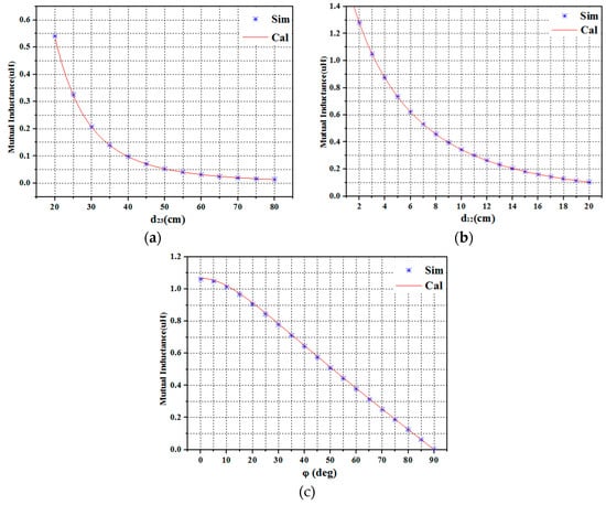
Figure 8.
Comparison of the mutual inductance calculations based on this paper and the mutual inductance simulation using Ansys Maxwell 16.0. (a) Mutual inductance of Tx coil and Rx coil, (b) mutual inductance of Tx coil and drive loop, (c) mutual inductance of Rx coil and load loop.
4. Experimental Results
In order to prove the feasibility of the above method, the four-coil system was established as shown in Figure 9. The structure parameters of the coils were the same as those of the simulation module in Table 2. The electrical parameters were measured by high-quality impedance analysis (MICROTEST 6379), as listed in Table 3. The operating frequency of the resonant coils can reach 3 MHz by adjusting the series capacitance of the resonant coils.
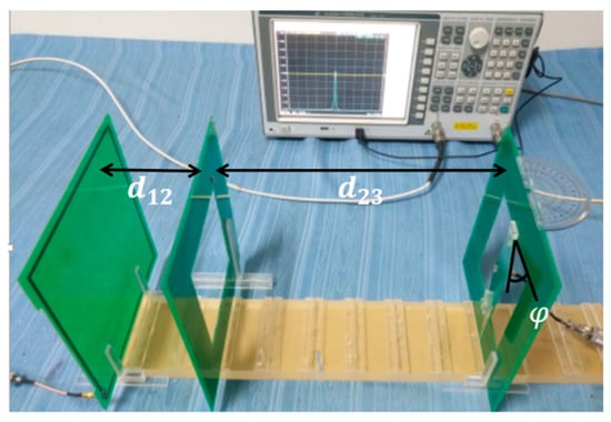
Figure 9.
Experimental setup of the four-coil WPT system.
Table 3.
Coil electrical parameters.
Firstly, all coils were aligned in the coaxial direction and d23 was the distance between the Tx coil and the Rx coil, which was fixed at 40 cm. Two ports of the network analyzer were connected to the load coil and the drive coil, respectively. The load and internal resistance of the source were both 50 Ω, accordingly. During the experiment, changing either d12 or φ, caused the transfer efficiency to vary accordingly, as shown in Figure 10. Figure 10a shows the variation of |S21|2 along with d12 when φ was fixed at 45 degrees. Obviously, there was an optimal d12 to maximize |S21|2. At this time, the measured value of Zin was approximately 50 Ω. Similarly, Figure 10b shows the variation of |S21|2 with φ when d12 was fixed at 7 cm. There was also an optimal φ that maximized the |S21|2. The experimental results were basically consistent with the simulation results based on the electrical parameters in Table 3, which showed that the circuit analysis, mutual inductance analysis and calculation in this paper were accurate. The trend of the curve showed that the transfer efficiency can be maximized by adjusting d12 and φ when the transmission distance is fixed.
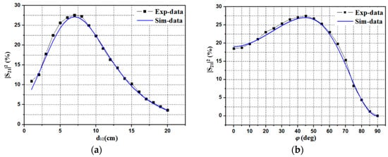
Figure 10.
The transfer efficiency at a fixed transmission distance, (a) changes to the d12 at fixed φ, (b) changes to the φ at fixed d12.
In Figure 10, the |S21|2 cannot represent the transfer efficiency because the magnitude of Zin is not equal to the internal resistance of the source.
Figure 11a shows the trend of transfer efficiency and transmission distance. d23 was changed from 25 cm to 80 cm with a step length of 5 cm. In an experiment that did not reach optimal load, φ was fixed at 0 degrees. Adjusting d12 caused the module of Zin to be close to 50 Ω, the magnitude of S21 to be the maximum. The maximum transfer efficiency under each distance was then obtained, and the results were marked by circular spots. In contrast, the next experiment reached the optimal load by changing the φ and using d12 to match the source that makes Zin equal to RS. The maximum transfer efficiency under each distance will then be attained; square spots indicate the results. In addition, the red and black lines represent the simulation results. Obviously, the transfer efficiency increased once the optimal load was reached. In particular, when the transmission distance was 40 cm, compared to before optimization, the transfer efficiency increased by nearly 11%. Figure 11b showed the optimal d12 and d23 at various distances in the case of reaching the optimal load. The experimental results were in good agreement with those calculated by Equation (9), which once again illustrates the accuracy of the theoretical analysis in this paper.
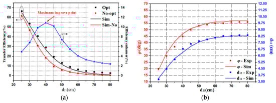
Figure 11.
(a) Maximum transfer efficiency at various transmission distances, (b) Optimal d12 and φ at various transmission distances.
5. Discussion
This paper proposed an impedance matching method, that enables the maximum efficiency at a fixed distance to be achieved. In essence, it is consistent with the impedance matching method mentioned in previous literature, but the means of implementation were different. The method in this paper is easier to realize in engineering. Especially with regard to charging portable devices and medical implant devices, using the method of this paper does not require complex internal circuit control. Only changing the position or angle of the electronic device or the patient is required to achieve efficient energy supply.
6. Conclusions
In this paper, it was proven theoretically that the transfer efficiency represented by scattering parameters can represent the traditional electrical transfer efficiency in the limit case. Furthermore, the optimal parameter expression was obtained. In addition, based on the Neumann formula, the numerical calculation method of the coaxial coil mutual inductance of parallel square coils and the concentric square coil with an included angle was obtained, and its accuracy was verified using the commercial software Maxwell. Finally, the four-coil WPT system experiment verified that the transfer efficiency can be maximized by adjusting the included angle between the load coil and the Rx coil, and the distance between the driven coil and the Tx coil. When compared to the situation prior to optimization, the maximum improved efficiency was improved by 11%. Angle adjustment can be realized simply in engineering applications, and the impedance matching of this system can be realized through angle adjustment in order to achieve maximum transfer efficiency. However, the coil structure in this paper was based on the PCB process, thus the power level of the system was limited and it is only applicable to portable devices, implanted medical devices and other low-power application scenarios. Meanwhile, the control of the angle has not been automated, which will be the next research goal. If this can be implemented, the integration and intelligence of the wireless transmission technology will be promoted.
Author Contributions
X.T. and M.L. conceived and designed the study; X.T. and C.R. gave the theoretical and data analysis; X.H. and C.L. gave the design of coils; Z.H. and Y.Z. revised the whole manuscript; M.L. gave the financial support during the research; X.T. wrote the paper.
Funding
This research was supported by the National Key R&D Program of China (Grant No. 2018YFB0106300), Scientific Projects of State Grid Corporation of China under Grant No. 0231132705, Huazhong University of Science and Technology.
Conflicts of Interest
The authors declare no conflicts of interest.
References
- Kurs, A.; Karalis, A.; Moffatt, R.; Joannopoulos, J.D.; Fisher, P.; Soljačić, M. Wireless Power Transfer via Strongly Coupled Magnetic Resonances. Science 2007, 317, 83–86. [Google Scholar] [CrossRef] [PubMed]
- Li, Z.; Zhu, C.; Jiang, J.; Song, K.; Wei, G. A 3 kW Wireless Power Transfer System for Sightseeing Car Supercapacitor Charge. IEEE Trans. Power Electron. 2017, 32, 3301–3316. [Google Scholar] [CrossRef]
- Xu, J.; Zeng, Y.; Zhang, R. UAV-Enabled Wireless Power Transfer: Trajectory Design and Energy Optimization. IEEE Trans. Wirel. Commun. 2018, 17, 5092–5106. [Google Scholar] [CrossRef]
- Luo, Z.; Wei, X. Analysis of Square and Circular Planar Spiral Coils in Wireless Power Transfer System for Electric Vehicles. IEEE Trans. Ind. Electron. 2017, 65, 331–341. [Google Scholar] [CrossRef]
- Zhao, L.; Thrimawithana, D.J.; Madawala, U.K.; Hu, A.P.; Mi, C.C. A Misalignment Tolerant Series-hybrid Wireless EV Charging System with Integrated Magnetics. IEEE Trans. Power Electron. 2018, 34, 1276–1285. [Google Scholar] [CrossRef]
- Rakhyani, A.K.R.; Mirabbasi, S.; Chiao, M. Design and Optimization of Resonance-Based Efficient Wireless Power Delivery Systems for Biomedical Implants. IEEE Trans. Biomed. Circuits Syst. 2011, 5, 48–63. [Google Scholar] [CrossRef] [PubMed]
- Kim, J.D.; Sun, C.; Suh, I.S. A proposal on wireless power transfer for medical implantable applications based on reviews. In Proceedings of the IEEE Wireless Power Transfer Conference, Jeju, Korea, 8–9 May 2014. [Google Scholar]
- Li, X.; Li, Y.P.; Tsui, C.Y.; Ki, W.H. Wireless Power Transfer System with ΣΔ Modulated Transmission Power and Fast Load Response for Implantable Medical Devices. IEEE Trans. Circuits Syst. II Express Briefs 2017, 64, 279–283. [Google Scholar] [CrossRef]
- Lee, D.S.; Lim, D.N.; Jeon, S.J.; Lee, K.S. Wireless power transfer system suitable for wristwatch type equipment. In Proceedings of the IEEE Wireless Power Transfer Conference, Jeju, Korea, 8–9 May 2014. [Google Scholar]
- Kindl, V.; Kavalir, T.; Pechanek, R.; Hruska, K. Basic operating characteristics of wireless power transfer system for small portable devices. In Proceedings of the Conference of the IEEE Industrial Electronics Society, Dallas, TX, USA, 29 October–1 November 2015. [Google Scholar]
- Cheon, S.; Kim, Y.H.; Kang, S.Y.; Lee, M.L.; Lee, J.M.; Zyung, T. Circuit-Model-Based Analysis of a Wireless Energy-Transfer System via Coupled Magnetic Resonances. IEEE Trans. Ind. Electron. 2011, 58, 2906–2914. [Google Scholar] [CrossRef]
- Hui, S.Y.R.; Zhong, W.; Lee, C.K. A Critical Review of Recent Progress in Mid-Range Wireless Power Transfer. IEEE Trans. Power Electron. 2014, 29, 4500–4511. [Google Scholar] [CrossRef]
- Zhang, Z.; Pang, H.; Georgiadis, A.; Cecati, C. Wireless Power Transfer—An Overview. IEEE Trans. Ind. Electron. 2018, 66, 1044–1058. [Google Scholar] [CrossRef]
- Chen, W.; Li, H.; Lu, W. Decoupling design of multi-coil wireless power transfer system with metal insulator. In Proceedings of the 2017 IEEE PELS Workshop on Emerging Technologies: Wireless Power Transfer (WoW), Chongqing, China, 20–22 May 2017. [Google Scholar]
- Arakawa, T.; Goguri, S.; Krogmeier, J.V.; Kruger, A.; Love, D.J.; Mudumbai, R.; Swabey, M.A. Optimizing Wireless Power Transfer from Multiple Transmit Coils. IEEE Access 2018, 6, 23828–23838. [Google Scholar] [CrossRef]
- Imura, T.; Hori, Y. Maximizing Air Gap and Efficiency of Magnetic Resonant Coupling for Wireless Power Transfer Using Equivalent Circuit and Neumann Formula. IEEE Trans. Ind. Electron. 2011, 58, 4746–4752. [Google Scholar] [CrossRef]
- Lee, W.S.; Son, W.I.; Oh, K.S.; Yu, J.W. Contactless Energy Transfer Systems Using Antiparallel Resonant Loops. IEEE Trans. Ind. Electron. 2013, 60, 350–359. [Google Scholar] [CrossRef]
- Wang, B.; Teo, K.H.; Nishino, T.; Yerazunis, W.; Barnwell, J.; Zhang, J. Experiments on wireless power transfer with metamaterials. Appl. Phys. Lett. 2011, 98, 254101. [Google Scholar] [CrossRef]
- Ahn, D. A Study on Magnetic Field Repeater in Wireless Power Transfer. IEEE Trans. Ind. Electron. 2013, 60, 360–371. [Google Scholar] [CrossRef]
- Chen, C.J.; Chu, T.H.; Lin, C.L.; Jou, Z.C. A Study of Loosely Coupled Coils for Wireless Power Transfer. IEEE Trans. Circuits Syst. II Express Briefs 2010, 57, 536–540. [Google Scholar] [CrossRef]
- Duong, T.P.; Lee, J.W. Experimental Results of High-Efficiency Resonant Coupling Wireless Power Transfer Using a Variable Coupling Method. IEEE Microw. Wirel. Compon. Lett. 2011, 21, 442–444. [Google Scholar] [CrossRef]
- Lim, Y.; Tang, H.; Lim, S.; Park, J. An Adaptive Impedance-Matching Network Based on a Novel Capacitor Matrix for Wireless Power Transfer. IEEE Trans. Power Electron. 2014, 29, 4403–4413. [Google Scholar] [CrossRef]
- Moriwaki, Y.; Imura, T.; Hori, Y. Basic study on reduction of reflected power using DC/DC converters in wireless power transfer system via magnetic resonant coupling. In Proceedings of the IEEE Telecommunications Energy Conference, Amsterdam, The Netherlands, 9–13 October 2011. [Google Scholar]
- Sample, A.P.; Meyer, D.A.; Smith, J.R. Analysis, Experimental Results, and Range Adaptation of Magnetically Coupled Resonators for Wireless Power Transfer. IEEE Trans. Ind. Electron. 2011, 58, 544–554. [Google Scholar] [CrossRef]
- Balakrishnan, A.; Palmer, W.D.; Joines, W.T.; Wilson, T.G. Inductance of planar rectangular-spiral strip conductors for low-profile inductors. In Proceedings of the IEEE Power Electronics Specialists Conference, Toledo, Spain, 29 June–3 July 1992. [Google Scholar]
- Kalantarov, P.L.; Tseytlin, L. Inductance calculation manual. 1992. [Google Scholar]
© 2019 by the authors. Licensee MDPI, Basel, Switzerland. This article is an open access article distributed under the terms and conditions of the Creative Commons Attribution (CC BY) license (http://creativecommons.org/licenses/by/4.0/).