1. Introduction
Noise is considered an environmental and social problem arising from consumption patterns and lifestyles in the accelerated urbanization process, which is generated by machines, railways, airplanes, loudspeakers, and so on [
1]. Increasing noise has been treated as one of the four major environmental pollutants [
2]. In particular, it has been reported that low frequency noise could result in hearing loss, headaches, sleep disturbance, inattention, and so on, and is therefore seen as one of the reasons for deterioration in people’s quality of life [
3]. Thus, methods and practices to reduce low frequency environmental noise are considered as one of the research focuses in the field of acoustical environment protection [
4,
5,
6]. Values of sound absorption coefficients in certain frequency ranges are the major index to evaluate the performance of a sound absorber with a limited total thickness [
7]. Meanwhile, considering the huge application prospects, a sound absorber reducing low frequency noise must not only have the advantage of a low manufacturing cost, good machinability, excellent fire resistance, and environmental friendliness, but also be easy to fabricate and install.
Many sound absorbers have been developed for low frequency noise reduction [
8,
9,
10,
11,
12]. Zhao et al. [
8] modified a microperforated panel by using a mechanical impedance plate, and the low frequency absorption was effectively enhanced without the need to increase the total thickness of the absorber. Cai et al. [
9] proposed ultrathin low frequency sound absorbing panels based on coplanar spiral tubes or coplanar Helmholtz resonators, and the efficacy of sound absorption by these panels was validated by the strong agreement between the theoretical analysis and experimental measurement. Perfect absorption of low frequency sound by the critically coupled subwavelength resonant system was proposed and developed by Long et al. [
10], and a highly efficient (> 80%) low frequency broadband absorption was achieved in the frequency range of 99.1–294.8 Hz. A review of sound absorption structures ranging from conventional materials with a porous microstructure to acoustic metamaterials was conducted by Yang and Sheng [
11], who found that with a sound absorber with a single sound absorbing structure, it was difficult to obtain a satisfactory sound absorption performance in a wide frequency range. Meanwhile, although the acoustic metasurface or metamaterial could achieve a high sound absorption coefficient in the low frequency range [
4,
6,
12], its complex structure and exquisite design limited its practical application in large-scale products.
Porous metal and microperforated metal panels are two common materials for sound absorption [
13], and both have the advantage of a low fabrication cost, good loading capacity, high mechanical strength, and so on [
14,
15,
16], which make the large-scale manufacture and application of sound absorbers made with these two materials feasible. Bravo and Maury [
17] studied the physical mechanisms involved in the sound attenuation and absorption of a microperforated panel backed by anisotropic fibrous material, which provided guidelines for further parametric or impedance optimization research. Peng [
18] investigated the sound absorption performance of porous material with perforated facing at high sound pressure levels, and a semi-empirical model was proposed. Li et al. [
19] attempted to enhance low- to mid-frequency sound absorption using parallel-arranged perforated plates with extended tubes and porous material, which had been proven effective in the 100–1600 Hz range. The sound absorption coefficient of a microperforated panel backed by porous sound-absorbing material was investigated by Liu et al. [
20], and a novel approach named 3D printing technology was proposed to fabricate the sound absorbers for acoustic application. These research products [
17,
18,
19,
20] indicated that a combination structure of porous metal and a microperforated metal panel was a promising candidate to develop a practical sound absorber for noise reduction in the low frequency range. In this study, parameter optimization of a combination structure of porous metal and microperforated panel, with a limited total thickness, was conducted with the aim of achieving better low frequency sound absorption performance.
Although several combination structures have already been developed [
17,
18,
19,
20], some deficiencies and defects have limited their practical application. Firstly, most of the current research has focused on the theoretical modeling of proposed sound absorbers and the actual limits for practical application have not been taken into consideration. One example is the limited total thickness of the sound absorber, which was determined by the space available for installation. Secondly, the influences of the structural parameters of the sound absorber were rarely studied in depth, and the finite experimental validations made it difficult to accurately gauge the absorption principle of the sound absorber. Thirdly, there were few practical methods to obtain optimal parameters for a given sound absorber under certain constraint conditions, especially when the structure of the investigated sound absorber was complex. Thus, in order to overcome these inadequacies, the combination structure of porous metal and microperforated panel was proposed and optimized. A theoretical model of the sound absorption coefficients of the combination structure was constructed through the transfer matrix method [
21] based on the Johnson—Champoux—Allard model [
22] and Maa’s theory [
23], which provided the foundation for further parameter optimization. Afterwards, the optimal structural parameters of the combination structure with a varied total thickness were obtained by a Cuckoo search algorithm [
24,
25]. Then, finite element simulation models for the sound absorption performance of the combination structures were constructed in the virtual acoustic laboratory [
26] with the aim of preliminarily verifying the reliability of the parameter optimization. After that, samples of porous metal and microperforated panels for the combination structure were prepared according to the obtained optimal structural parameter, and the assembled sound absorbers were measured based on the standing wave method [
27,
28]. By comparing the theoretical data, the simulation data, and the experimental data of the obtained optimal sound absorbing structures, a novel method for the development of a low frequency sound absorber is proposed.
2. Theoretical Modeling of the Combination Structure
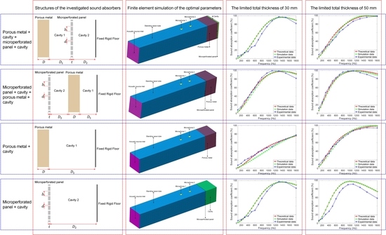
Two combination structures made of porous metal and a microperforated panel were investigated, as shown in
Figure 1a,b. One consisted of a porous metal + cavity + microperforated panel + cavity, and the other consisted of a microperforated panel + cavity + porous metal + cavity. Two traditional sound absorbers consisting of a porous metal + cavity and a microperforated panel + cavity, as shown in
Figure 1c,d, were also investigated as a contrast. The structural parameters of the porous metal were its thickness
and the corresponding cavity length
, and those of the microperforated panel were the thickness of the panel
, the diameter of the microhole
, the distance of the neighboring microholes
(distribution of the microholes was in a square arrangement), and the corresponding cavity length
, which were consistent with the labels of these structural parameters in
Figure 1.
Theoretical models of the sound absorption coefficients of these sound absorbing structures were constructed through the transfer matrix method [
21], as shown in Equation (1). Here,
is the sound absorption coefficient;
and
are two components of the total transfer matrix of the sound absorber, which can be calculated through Equations (2)–(5) for the corresponding sound absorbing structures in
Figure 1a–d;
is the density of the air, 1.21 kg/m
3;
is the acoustic velocity in air, 340 m/s;
and
represent the real part and imaginary part of one complex number, respectively.
In Equations (2)–(5), , , , and represent the transfer matrix of the porous metal, of the cavity backing the porous metal, of the microperforated panel, and of the cavity backing the microperforated panel, respectively.
Transfer matrix
of the porous metal can be calculated by Equation (6) based on the Johnson—Champoux—Allard model [
22]. Here,
is the number of waves in the porous material, which can be obtained by Equation (7);
is the characteristic impedance of the porous material, which can be obtained by Equation (8).
In Equations (7) and (8),
is the angular frequency, which can be obtained by Equation (9);
is the complex effective density, which can be obtained through Equation (10);
is the complex effective bulk modulus, which can be calculated with Equation (11).
In Equation (9),
is the sound frequency. In Equations (10) and (11),
is the specific heat ratio of the air, 1.40;
is the static pressure of the air, 1.013*10
5 Pa;
is the Nusselt number, 4.36;
is symbol of the imaginary number;
is the Prandtl number, 0.71 [
7,
13,
22,
28]. Meanwhile, in Equations (10) and (11), the static flow resistivity
and porosity
of the porous metal used in this study were 9.2*10
3 Pa·s/m and 0.9, respectively, which were obtained by the measurement based on their definitions.
The transfer matrix
of the microperforated panel can be obtained by Equation (12). Here,
is the acoustic impedance rate of the microperforated panel, which consists of the real part
and the imaginary part
, as shown in Equation (13). The
and
can be calculated through Equations (14) and (15), respectively.
In Equations (14) and (15),
is the viscosity coefficient of the air, 1.506 × 10
−5 m
2/s;
is the temperature conduction coefficient of the metal panel, 2.0 × 10
−5 m
2/s;
is the microperforating rate, which can be calculated by Equation (16);
is the acoustic resistance constant, which can be obtained by Equation (17);
is the acoustic mass constant, which can be derived by Equation (18) [
8,
16,
23]. In Equations (17) and (18),
is the perforated panel constant, which can be calculated through Equation (19).
The transfer matrices
of the cavity backing the porous metal and
of the cavity backing the microperforated panel can be calculated by Equations (20) and (21), respectively.
In this way, the theoretical sound absorption coefficients of the investigated sound absorbers in
Figure 1 could be obtained, forming the theoretical basis for further parameter optimization, finite element simulation, and experimental validation.
3. Parameter Optimization for Better Sound Absorption Performance
According to the constructed theoretical models, the structural parameters of the investigated sound absorbers were optimized by a Cuckoo search algorithm, which aimed to achieve satisfactory sound absorption performance in the low frequency range of 100–1800 Hz when the total thickness of the sound absorber was limited. The average sound absorption coefficient of the sound absorber in the frequency range of 100–1800 Hz was treated as the judging index and the aim of the parameter optimization was to obtain its maximal value, as shown in Equation (22).
There were two major constraint conditions for the investigated sound absorber. First was the limit for the total thickness of the sound absorber,
, which represented the space available in which to install the sound absorber. The total thickness of the sound absorber
included the thickness of the porous metal
, the length of the cavity backing the porous metal
, the thickness of the microperforated panel
, and the length of the cavity backing the microperforated panel
, as shown in Equation (23).
According to the definition of the microperforated panel, the diameter of the microhole
should be smaller than 2 mm. Meanwhile, taking the manufacturing cost and practical application into account, the thickness of the panel should be larger than 0.1 mm, the diameter of the microhole should be larger than 0.1 mm, and the distance to the neighboring microholes should be larger than 1 mm. This second constraint condition, regarding the microperforated panel, is summarized in Equation (24).
Based on the optimization target in Equation (22) and the constraint conditions in Equations (23) and (24), the structural parameters of the investigated sound absorbers were optimized by a Cuckoo search algorithm [
16,
24,
25]. The limited total thicknesses investigated were 30 mm, 50 mm, and 100 mm, and the optimal structural parameters obtained for these investigated sound absorbers are summarized in
Table 1,
Table 2 and
Table 3, respectively. Values of the optimal parameters are shown to four significant digits after the decimal point. It can be seen from the theoretical results that the sound absorber consisting of a microperforated panel + cavity + porous metal + cavity achieved the best sound absorption performance. Its average sound absorption coefficients reached 71.4354%, 80.2518%, and 90.3554% when the limited total thicknesses were 30 mm, 50 mm, and 100 mm, respectively. Meanwhile, it should be noted that the optimal length of the cavities backing the porous metal and the microperforated panel were all 0, no matter what the limited total thickness was, which indicates that the sound absorber simply consisted of the microperforated panel and the porous metal. Besides the satisfactory sound absorption performance, this sound absorber also had the additional advantage of a high mechanical strength, great convenience for transportation, installation, application, and maintenance, and good machinability, because there were no gaps among the microperforated panel, the porous metal, and the installed surface. With respect to the sound absorber consisting of porous metal + cavity + microperforated panel + cavity, it was found that its average sound absorption coefficients improved from 65.0575% to 88.8120% when the limited total thickness increased from 30 mm to 100 mm, a slightly smaller improvement than that found for the sound absorber consisting of microperforated panel + cavity + porous metal + cavity. The major reason for this phenomenon is thought to be that the low frequency sound absorption capacity of the porous metal was lower than that of the microperforated panel with the same total thickness, and absorption of the low frequency sound by the microperforated panel required a large cavity. Thus, it would be better to put the microperforated panel in front of the porous metal in the combination structure. It was observed that the optimal length of the cavity for the sound absorber consisting of porous metal + cavity was 0 in all three conditions, and the available space was filled with the porous metal, which indicated that sound absorption performance of the pure porous metal would be better than that of the porous metal + cavity, with the same limited total thickness [
7].
The theoretical sound absorption coefficients of the investigated sound absorbers are summarized in
Figure 2a–c, which correspond to the limited total thicknesses of 30 mm, 50 mm, and 100 mm, respectively. It can be observed from
Figure 2a that when the limited total thickness was 30 mm, the sound absorption coefficients of the sound absorber consisting of microperforated panel + cavity + porous metal + cavity were completely consistent with those of the sound absorber consisting of microperforated panel + cavity because the obtained optimal structural parameters for these two sound absorbers are the same in
Table 1. It can also be observed that the sound absorption coefficients of the porous metal were significantly determined by its thickness. The larger the thickness, the better its sound absorption performance, which is consistent with the normal sound absorption principle of porous material [
7,
13,
28]. Meanwhile, it can be seen from
Figure 2c that when the limited total thickness reached 100 mm, with the exception of the sound absorber consisting of microperforated panel + cavity, all sound absorbers achieved a similar sound absorption performance, which is consistent with the results in
Table 3.
4. Preliminary Verification by Finite Element Simulation
According to the theoretical optimal structural parameters obtained by Cuckoo search algorithm, the finite element simulation models for the four investigated sound absorbers were constructed in the virtual acoustic laboratory, and schematic diagrams of the simulation models when the total thickness was 50 mm are shown in
Figure 3. The plane wave was introduced in the acoustic source inlet, which was treated as the incident sound source. Two microphones were utilized to measure the incident sound wave and the reflected sound wave in the standing wave tube, which were used to calculate the sound absorption coefficient. In the model, porous metal was characterized by setting its structural parameters, which included the static flow resistivity, porosity, bulk density, specific heat ratio, and so on. Meanwhile, the microperforated panel was represented by the acoustic transfer relation admittance loading at the inner surface and outer surface of the panel. Dimensional parameters of the porous metal, microperforated panel, and the cavity were coincident with the obtained optimal parameters in
Table 2. In this way, the real part and imaginary part of the sound pressure at microphone 1 and those at microphone 2 could be obtained from the simulation process and exported as the original data, and the sound absorption coefficient could be calculated.
Similarly, the finite element simulation models of the four investigated sound absorbers with limited total thicknesses of 30 mm and 100 mm were constructed according to the theoretical optimal structural parameters in
Table 1 and
Table 3, respectively. Comparisons of the theoretical results and the simulation results are summarized in
Figure 4. It can be observed that simulation data of the microperforated panel + cavity sound absorber agreed well with its theoretical data, and that there were notable differences between simulation data of the porous metal and its theoretical data, especially when the limited total thickness was 30 mm. One important reason for this phenomenon is that Maa’s theory is widely recognized as an accurate model to describe the sound absorption process of the microperforated panel [
8,
16,
23], so it was easy to represent its characteristics by the acoustic transfer relation admittance in the finite element simulation model. However, many theoretical models have been developed to describe the sound absorption mechanism of porous material, such as the Johnson—Champoux—Allard model [
7,
13,
22,
28], the Delany—Bazley—Miki model [
29,
30], the Craggs model [
31,
32], and so on. Meanwhile, there were two frame types for the porous material, rigid and limp, which made it difficult to select the appropriate models and parameters for the porous metal in the finite element simulation model. Therefore, the differences between the simulation data and theoretical data of the porous metal were larger than those of the microperforated panel. It was also found that the differences between the simulation data and the theoretical data of the porous metal + cavity + microperforated panel + cavity sound absorber and those of the microperforated panel + cavity + porous metal + cavity sound absorber were larger than those of the microperforated panel and smaller than those of the porous metal, which were well accordant with the causal analysis because the combination structures consisted of porous material and microperforated panel. With an increase in the limited total thickness from 30 mm to 100 mm, the differences between simulation data and theoretical data of each sound absorber were gradually reduced because the sound absorption coefficients were close to their limits in this low frequency range of 100–1800 Hz. Although the prediction of sound absorption coefficients through the constructed finite element simulation model had some deviations, it was a significative preliminary verification of the obtained theoretical optimal structural parameters of each sound absorber and could be treated as an effective supplement for the further experimental validation. It is generally known that the single-piece fabrication of a porous metal and of microperforated panels is high-cost and time-consuming, and the experimental measurement of sound absorption coefficients of the sound absorber also took a lot of time, which not only decreased the research efficiency but also increased the research cost.
5. Experimental Validation of the Optimal Combination Structure
Although the average sound absorption coefficient of the sound absorber increases along with an increase in the limited total thickness, the increase in the dimensional size of the sound absorber would require more installation space, which might limit its practical application. Moreover, the larger the sound absorber, the higher its fabrication cost. Therefore, experimental validations of the optimal sound absorbers when the limited total thickness was 30 mm and 50 mm were conducted with an AWA6128A detector (Hangzhou Aihua Instruments Co., Ltd., Hangzhou, China) according to the standing wave method [
13,
27,
28], and a schematic diagram of the experimental system is shown in
Figure 5. The porous metal used was porous copper, which was purchased from YiYang Foammetal New Materials Co., Ltd., Yiyang, China. The microperforated panel was fabricated by the laser beam drilling of spring steel according to the optimal structural parameters in
Table 1 and
Table 2 [
16,
33]. After the required samples were prepared, they were assembled to form the desired sound absorbers investigated in this study. These sound absorbers were measured by an AWA6128A detector to obtain their sound absorption coefficients in the frequency range of 100–1800 Hz. According to the operating instruction of the AWA6128A detector, the cross-sectional shapes of the detected sound absorbers were round, and their diameters were 96 mm. Meanwhile, the measured sound frequencies were 100 Hz, 200 Hz, 300 Hz, 400 Hz, 500 Hz, 600 Hz, 700 Hz, 800 Hz, 950 Hz, 1100 Hz, 1300 Hz, 1500 Hz, and 1800 Hz, which consisted of 13 frequency points.
Comparisons of the theoretical data, simulation data, and experimental data for the four investigated sound absorbers with limited total thicknesses of 30 mm and 50 mm are shown in
Figure 6 and
Figure 7, respectively. It was found that the experimental data were basically coincident with the theoretical data and the simulation data, which indicated that the constructed theoretical sound absorption models and finite element simulation models for these four sound absorbers were effective and accurate. The actual average sound absorption coefficient for the sound absorber consisting of microperforated panel + cavity + porous metal + cavity was 62.9615% and 73.5923% when the limited total thickness was 30 mm and 50 mm, respectively, exhibiting a satisfactory sound absorption performance in the low frequency range.
The average sound absorption coefficients achieved in the theoretical analysis, finite element simulation, and experimental measurement of sound absorbers with a limited total thickness of 30 mm and 50 mm are shown in
Table 4 and
Table 5, respectively. It was found that the actual average sound absorption coefficients for the combination structure of microperforated panel + cavity + porous metal + cavity were clearly better than those of the porous metal + cavity + microperforated panel + cavity sound absorber with the same constraint conditions, which indicated that the microperforated panel + cavity + porous metal + cavity structure was an efficient sound absorber for low frequency noise reduction. Meanwhile, it was observed that there were obvious differences between the theoretical average sound absorption coefficients of the sound absorber consisting of microperforated panel + cavity and its actual value. The difference reached 15.8652% and 18.922%, respectively, when the limited total thickness was 30 mm and 50 mm. On the contrary, for the sound absorber of porous metal, the difference was 5.8649% and 10.6585%, respectively, when the limited total thickness was 30 mm and 50 mm. A major reason for this may be that it was difficult to fabricate a microperforated panel completely consistent with its structural parameters, with the fabrication error being determined by the processing capability and kinematic accuracy of the manufacturing equipment. Moreover, the vibration of the microperforated panel under acoustic excitation could result in errors as well. These phenomena would certainly affect the two combination structures. When the limited total thickness was 30 mm and 50 mm, for the porous metal + cavity + microperforated panel + cavity sound absorber, the difference was 15.8652% and 16.673%, respectively; for the microperforated panel + cavity + porous metal + cavity sound absorber, the difference was 8.4739% and 6.6595%, respectively. Though there existed deviations between the theoretical and experimental data for the four investigated sound absorbers, a novel method to develop low frequency sound absorbers by parameter optimization was proposed and validated.
6. Conclusions
This study aimed to develop low frequency sound absorbers by the optimal combination of porous metal and a microperforated panel. Through theoretical modeling, parameter optimization, finite element simulation, sample preparation, and experimental measurement, the following conclusions were obtained.
(1) The optimal combination structure of microperforated panel + cavity + porous metal + cavity was a valuable low frequency sound absorber, and its actual average sound absorption coefficient in the low frequency range of 100–1800 Hz reached 62.9615% and 73.5923%, respectively, when the limited total thickness was 30 mm and 50 mm.
(2) Sound absorption coefficients of the optimal sound absorbing structure were primarily verified by the finite element simulation model and were further validated by standing wave tube measurement, which proved that the sound absorption performance of the sound absorber could be improved through parameter optimization by Cuckoo search algorithm.
(3) The experimental data was consistent with the theoretical data and the simulation data of sound absorption coefficients for the four sound absorbers, which proves the effectiveness, reliability, and accuracy of the constructed theoretical sound absorption model and the finite element simulation model. This could serve as the reference and guidance for the design and optimization of novel sound absorbers with given requirements, which is desirable to shorten the design cycle and improve development efficiency.
In this study, combination structures were explored with the aim of developing thin low frequency sound absorbers to mitigate environmental noise, and the obtained excellent sound absorption performance of the combination structure consisting of microperforated panel + cavity + porous metal + cavity was effective in absorbing low frequency noise, making it favorable for applications in acoustic environmental protection and industrial noise reduction.


