Article

Mechanical Properties, Tissue Structure, and Elemental Composition of the Walking Leg Tips of Coconut Crabs

1
National Institute for Materials Science, 1-2-1, Sengen, Tsukuba 305-0047, Ibaraki, Japan
2
Okinawa Churashima Foundation, 888 Ishikawa, Motobu 905-0206, Okinawa, Japan
*
Author to whom correspondence should be addressed.
J. Mar. Sci. Eng. 2024, 12(4), 639; https://doi.org/10.3390/jmse12040639
Submission received: 18 March 2024 / Revised: 4 April 2024 / Accepted: 9 April 2024 / Published: 10 April 2024
(This article belongs to the Special Issue Evolution and Ecology of Crustaceans and Their Applications)

Abstract

:
The coconut crab, Birgus latro, has black protrusions on the tops of its walking legs and claw fingers. In addition, there are regularly aligned small black protrusions on parts of the exoskeleton surface of the claws and leg. In this study, the elemental composition, crystal structure, tissue structure, and mechanical properties of these protrusions were studied using a materials science approach, and the results were compared with those of mineralized cuticle. These leg tips were found to be a non-calcified fibrous tissue of α-chitin connected to the mineralized cuticle. The tip of the second walking leg was elongated and had a pointed shape with an oval cavity at its center that was more than 1000 times larger than the pore tubes (100–350 nm) of the mineralized cuticle. It was very soft, with a hardness of 0.4 GPa, corresponding to 11–12% of the hardness of the hard exocuticle and 55–57% of the hardness of the soft endocuticle. The elastic modulus of 8.0 GPa obtained by means of nanoindentation testing was consistent with that of α-chitin fibers of shrimp shells obtained by means of tensile testing. These soft protrusions provide a secure grip on the surfaces of trees or rocks and protect the claw fingertips. It was concluded that the black protrusions are related to a unique ecological (engaging in vertical movements, entering and exiting limestone caves, and escape behavior) aspect of the coconut crab, the largest terrestrial crustacean.

1. Introduction

Organisms evolve to survive in harsh natural environments and have morphologies and internal tissue structures with the necessary characteristics in the necessary places. The study of these characteristics is expected to be useful in the development of novel high-performance materials that exceed the current state [1,2,3,4,5,6,7,8,9,10,11,12,13].
The largest terrestrial crustacean, the coconut crab, Birgus latro [14,15], shown in Figure 1a,b, is a rare organism with a pinching force more than 90 times its body weight [16,17]. Its robust claw is the coconut crab’s strongest weapon, and it is also a tool for crushing hard palm nuts that other organisms cannot eat. The mineralized exoskeleton of the cheliped consists of a hard exocuticle layer (about 10% of the exoskeleton’s thickness) and a soft endocuticle layer (about 90% of the exoskeleton’s thickness) [16]. The exocuticle has a twisted plywood pattern structure (called a Bouligand structure) [7] stacked parallel to the surface. On the other hand, the endocuticle has a porous structure with many regularly arranged pores perpendicular to the surface. The structures of these layers are the same not only for the cheliped, but also for the walking legs, the shield, and the pleon [18]. The tooth-like white denticles present on the pinching side of the claw have a columnar structure perpendicular to the surface [19], and their microstructure becomes denser closer to the surface. The denticles have an abrasion resistance comparable to that of the exocuticle layer [20].
When the coconut crab intimidates enemies, and when it climbs trees to feed on nuts of Pandanus odoratissimus and palm nuts, the tip of the second walking leg (2WL) is mainly used. This tip is black, elongated, and pointed; it is clearly distinguishable from the exoskeleton, as shown in Figure 1c,d. This black protrusion is also visible on the tips of the third and fourth walking legs. In addition, although it is shaped like a spatula, which protects the fingertips, there is also a similar black protrusion on the tip of the claw finger (see Figure 1e and Figure S1 of the Supporting Materials). It can be predicted that these black protrusions are a material that is different from the exoskeleton, but there are many unknown points, such as the tissue structure, elemental composition, and mechanical properties. Here, we investigated the main composition, crystal structure, tissue structure, and mechanical properties of the black protrusions using a materials science approach. We compared the results with those of mineralized cuticles (exocuticle and endocuticle). The role of the black protrusions in coconut crabs was then discussed.

2. Materials and Methods

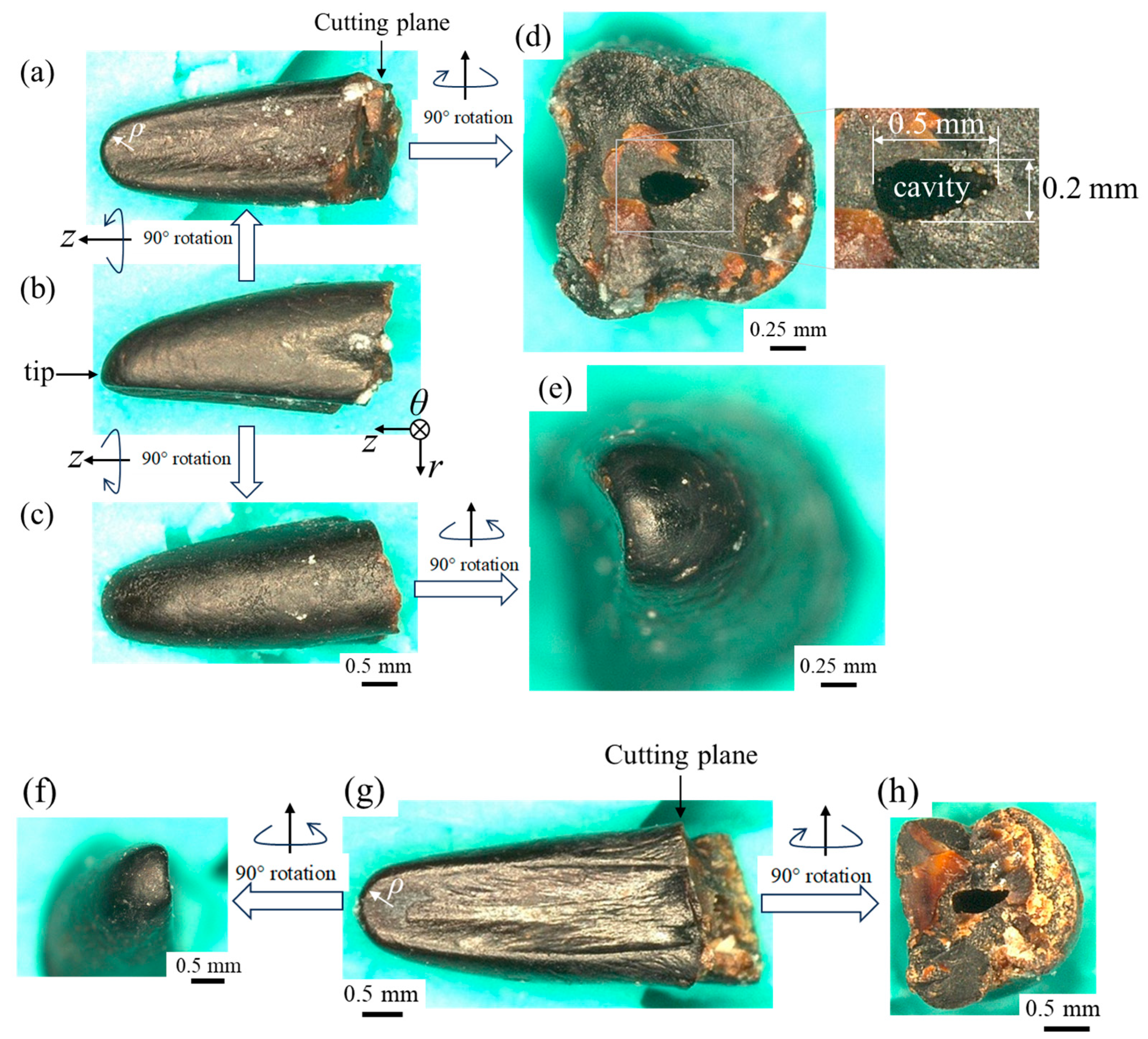
2.1. Sample Preparation

The tip of the right 2WL of the coconut crab (sample A: male, body weight (BW) = 1070 g) was used in the present paper. Since the tissue structure, crystal structure, elemental composition, and mechanical properties of the exoskeleton of each body part in sample A have already been investigated in previous papers [16,18], the black protrusion of the 2WL of sample A was selected as the sample for analysis. In addition, to observe the fracture surface of the black protrusion of the right 2WL tip, we obtained a coconut crab (sample B: male, BW = 964 g) of almost the same size from a local market in Okinawa. The crab used as sample B is displayed in Figure 1.
The 2WL of sample A was polished by hand until the cross sections near the middle of the tip, and then the mounting cup in which the sample was set was filled with epoxy and left to cure at room temperature for 12 h. To ensure that the epoxy penetrated into the sample voids, the sample was placed under vacuum for 600 s shortly after the epoxy was added. The sample was then ground with SiC paper, polished with 9, 3, and 1 μm diamond suspensions, and finally polished with a 0.05 μm alumina suspension. The cross-sectional image of the sample was obtained by merging multiple images using an optical micrograph (OM) (ECLIPSE LV150; Nikon Solutions, Tokyo, Japan). Since the embedded sample needed to be coated with osmium (Os) using a Neo Osmium Coater (Meiwafosis, Tokyo, Japan) to characterize the microstructure and composition using a scanning electron microscope (SEM) and an energy dispersive X-ray spectroscope (EDS), respectively, the local mechanical properties were measured before the microstructural analysis.

2.2. Vickers Hardness and Nanoindentation Testing

The local mechanical properties were investigated using a Vickers hardness tester (HMV-G30; SHIMAZU, Kyoto, Japan) and nanoindentation tester (ENT-NEXUS; ELIONIX, Tokyo, Japan) with a Berkovich diamond indenter. The tests were performed at room temperature (21–23 °C) after polishing. Vickers tests were performed five times for the cross-section of the black protrusion. The measurement was performed with the application of 98.07 mN for 15 s. The nanoindentation tests were first performed five times near the Vickers indentation on the black protrusion and then performed at intervals of 5 to 10 μm from the surface inward along two parallel lines. Tests were performed 44 times for each line. The loading curve consisted of a loading rate of 1 mN/s, holding for 5 s at the maximum load of 5 mN, followed by a 5 s unloading time. HIT and Er were analyzed from the unloading curve using the Oliver–Pharr method [21], which has been used in biological studies [16,18,19,20,22,23,24,25,26,27]. For comparison, tests were also performed on the exocuticle and endocuticle of the sample (area of the blue rectangles in Figure 2a).

2.3. X-ray Diffraction

XRD analysis was performed to determine the crystal structure of the black protrusion. Microdiffraction experiments were performed at room temperature using a commercial X-ray diffractometer (SmartLab; Rigaku Co., Ltd., Tokyo, Japan) equipped with a HyPix-3000 single-photon counting detector. Cu Kα X-ray radiation (λ = 1.5418 Å) was generated by a Cu rotator anode with an operating voltage and current of 45 kV and 200 mA, respectively. A micro X-ray beam with a diameter of 0.1 mm was shaped by a collimator. The resulting two-dimensional diffraction images were then converted to one-dimensional diffraction spectra with a step size of 0.02° using 2DP (ver. 2.1.6.0) software (Rigaku Co., Ltd., Tokyo, Japan). XRD was measured at five positions near the top and five positions near the center of the black protrusion. The measurement position for XRD was determined using a movable x–y stage with an accuracy of approximately 200 μm and an observation camera.

2.4. Microstructure and Elemental Compositions

After nanoindentation testing and XRD analysis, the sample was coated with a approximately 2 nm thick layer of Os. A focused ion beam (FIB)–SEM dual-beam instrument (Scios2; Thermo Fisher Scientific, Waltham, MA, USA) with an accelerating voltage of 2 kV and a secondary electron detector in a chamber or an in-lens annular backscattered electron detector was used for the microstructural characterization. The composition was analyzed by means of EDS attached to this FIB–SEM instrument. A large silicon drift detector (Ultim Max 170; Oxford Instruments, Abingdon, Oxfordshire, GB; accelerating voltage: 15 kV) ensured high detection efficiency and low statistical error in the quantitative analysis. In the EDS quantitative analysis, aluminum (Al) was excluded because an alumina suspension was used for polishing.

2.5. Fracture Surfaces

A fracture surface was observed to reveal the microstructures of the black protrusion. The black protrusion was cut from the 2WL of sample B with a microgrinder, and it was then left in air for more than 48 h. The dry black protrusion was broken by hitting the back of a chisel with a hammer before SEM observation, and two samples—both perpendicular and parallel to the surface of the black protrusion tip—were taken. Then, an Os coating with a thickness of about 2 nm was applied to the fracture surfaces to obtain a clear microstructure image of the organisms by eliminating the electron charge-up. The fracture surfaces were observed by means of SEM (JSM-7900F; JEOL, Tokyo, Japan; accelerating voltage: 2 kV; detector: Everhart–Thornley secondary electron detector (ET–SE)).

3. Results

3.1. Mechanical Properties

Figure 2a shows a cross-sectional micrograph of the 2WL of sample A after polishing. Based on the differences in contrast, the cross section of the 2WL can be roughly classified into five areas: the black protrusion (tip), the small protrusion, the exocuticle, the endocuticle, and the setae. The leg tip is connected to the mineralized cuticle, and its surface appears to be connected to the exocuticle (* in Figure 2a). The exoskeleton consists of a very thin epicuticle of the outermost surface, a thin exocuticle, a thick endocuticle adjacent to it, and a seta transverse the exoskeleton. This is similar to other crustaceans [7,22,28,29]. The area that connects with the black protrusion stretches from the mineralized cuticle toward the center of the protrusion and displays different levels compared to the endocuticle (** in Figure 2a). The small black protrusion on the left cross section is connected to the exocuticle present on the surface of the exoskeleton. The OM image of the leg tip after Vickers hardness testing is shown in Figure 2b. Here, the leg tip was covered by a very thin epicuticle. The presence of such an epicuticle has also been confirmed in the claw fingers and denticles of the coconut crab [16,18,19]. The average Vickers hardness, HV0.01, including the standard deviation, of the black protrusion was 31.0 ± 0.0, and there was no variation. As a comparison, the HV0.01 of the exocuticle and endocuticle was 251.36 ± 2.64 and 56.19 ± 1.78, respectively. The OM image of the leg tip after nanoindentation testing and the load–depth curves for the five tests are shown in Figure 2c,d. The mechanical properties (hardness: HIT; reduced elastic modulus: Er) were HIT = 0.42 ± 0.0056 (GPa) and Er = 8.54 ± 0.059 (GPa). For comparison, the exocuticle had HIT =3.60 ± 0.15 (GPa) and Er = 61.28 ± 0.44 (GPa), and the endocuticle had HIT = 0.70 ± 0.089 (GPa) and Er = 22.85 ± 1.57 (GPa). These values for the exocuticle and endocuticle of the 2WL are consistent with the results of the claw exoskeleton in previous papers [16,18,20]. The mechanical properties (HV0.01, HIT, and Er) of the leg tip are significantly inferior compared to those of the mineralized cuticle. Furthermore, the value of the standard deviation corresponding to the variation is very small. In general, the variation in the hardness of the exoskeleton of organisms is very high due to local differences in the grade of mineralization and the microstructure [18,22,23,26,30].
Figure 2. The second walking leg of sample A; body weight = 1070 g and thoracic length = 62.0 mm. (a) Optical micrographs of a cross section of the walking leg tip after polishing, (b) enlarged micrograph near the tip, including Vickers indentations, (c) area where 5 nanoindentation tests were performed and 5 indentations were made after the test, and (d) load–displacement curves of 5 tests. Here, in (a), * is boundary between leg tip and exocuticle, ** is area connecting leg tip and endocuticle, and blue rectangles denote areas where Vickers hardness and nanoindentation testing was conducted as a comparison.
Jmse 12 00639 g002
Figure 3 shows the OM image of the leg tip after nanoindentation testing and the variations of HIT and Er with the distance from the outer surface, r. Here, the two lines are parallel and separated by 100 μm. The HIT and Er gradually increased with r and then became constant (HIT = 0.4 GPa and Er = 8.0 GPa). The soft area with a thickness of less than 40 μm is the epicuticle layer covering the surface, as shown in Figure 3a. It can be seen that the properties of the epicuticle are inferior compared to those of the epoxy resin. The variability of the mechanical properties within the leg tip is much smaller than that of the exocuticle and endocuticle [18,20].

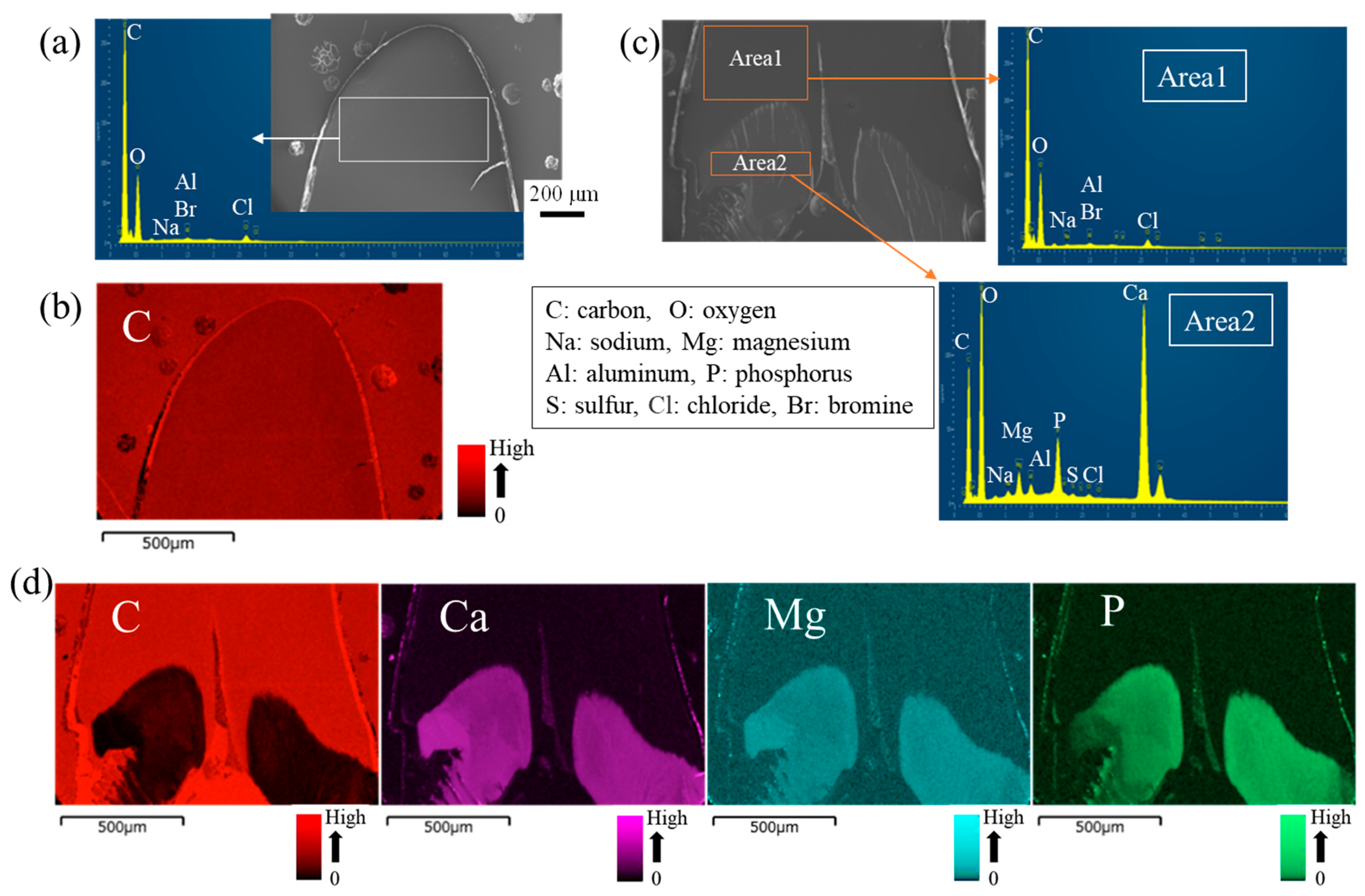
3.2. Crystal Structures and Elemental Compositions

The results obtained via X-ray diffraction (XRD) are shown in Figure 4. For the comparison of each layer comprising the exoskeleton, all XRD patterns of the black protrusion and exoskeleton (exocuticle, endocuticle, and denticle) are shown in Figure S2 of the Supporting Materials. The crystalline structures of the black protrusion were found to be α-chitin [31]. In short, the black protrusions are non-mineralized, which is different from the mineralized rigid exoskeletons (main crystalline structures are calcite).
Figure 5 shows SEM images and EDS results of the top and base of the black protrusion. In the black protrusion, structures such as a twisted plywood pattern in the exocuticle, a porous structure in the endocuticle, and a columnar structure in the denticle could not be observed using SEM. Major components—carbon (C) and oxygen (O)—and minor components—sodium (Na) and chloride (Cl)—were found in the top area of the black protrusion, as shown in Figure 5a,b. NaCl ions are used as counter ions for proteins, especially those that stabilize chitin fibrils. These minor components have also been found in the cuticle of the coconut crab [18], mud crab [22], brown crab [24], and American lobster [32], which consist of an α-chitin-containing exoskeleton. Here, although trace amounts of bromine (Br) have been confirmed in the non-calcified crustacean cuticle [27,33], it was difficult to confirm the existence of Br in the present study, because the Kα peak of Al overlaps with the Lα peak of Br. In the bottom area shown in Figure 5c, the same components as in the top area were found in area 1, but mineral, calcium (Ca), magnesium (Mg), and phosphorus (P) were found in area 2. The main components in area 1 were 64.6 C–33.9 O (all in weight %), and those in area 2 were 27.7 C–47.3 O–19.5 Ca–1.2 Mg–2.9 P. Area 2 corresponds to the part of the area (**) connecting the leg tip and the endocuticle, as shown in Figure 2a. This area extends from the cuticle to the center of the leg tip. The EDS maps shown in Figure 5d reveal that the whole connecting area contains minerals, and the C concentrations in this area are lower than in the leg tip.

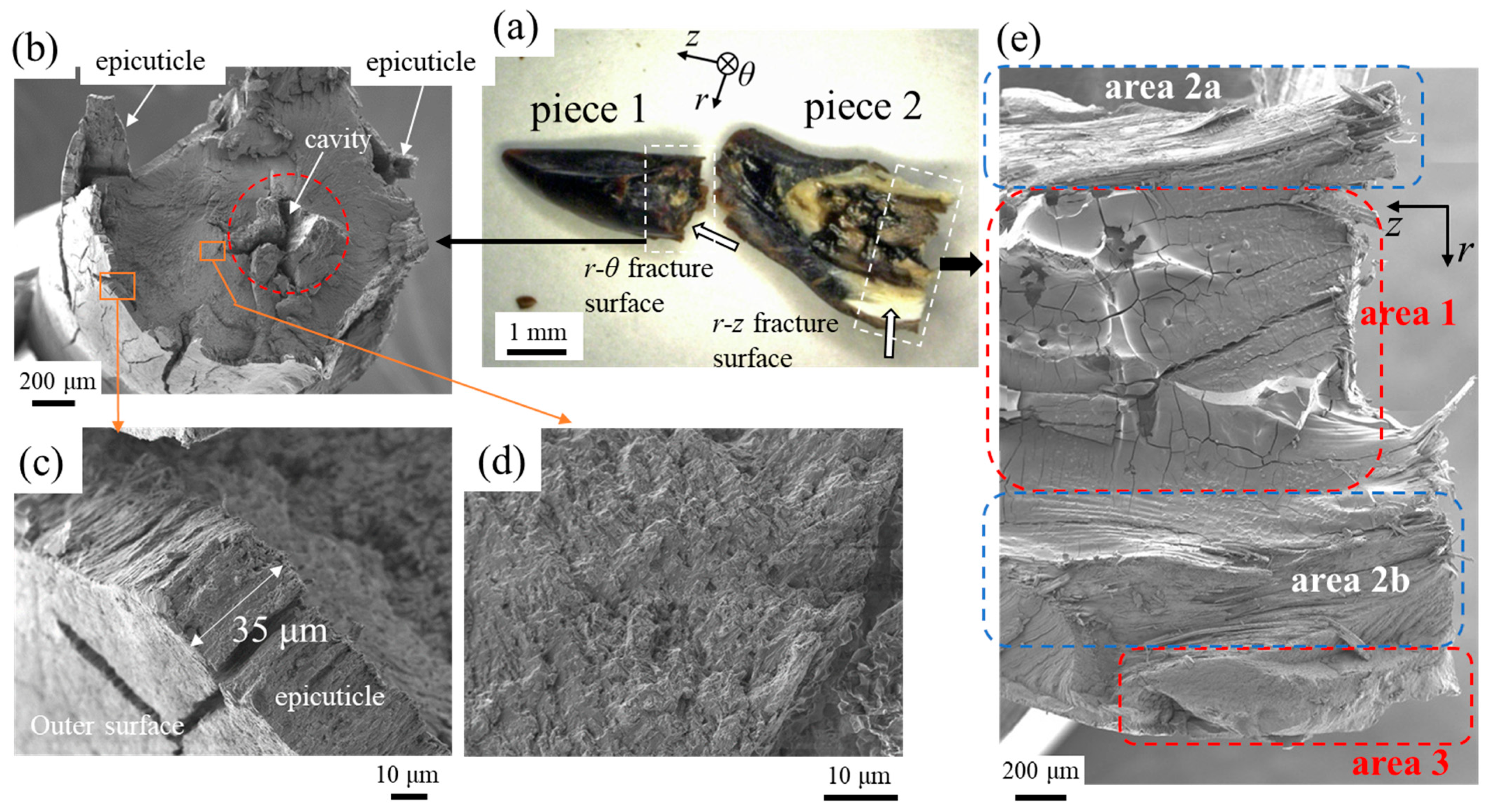
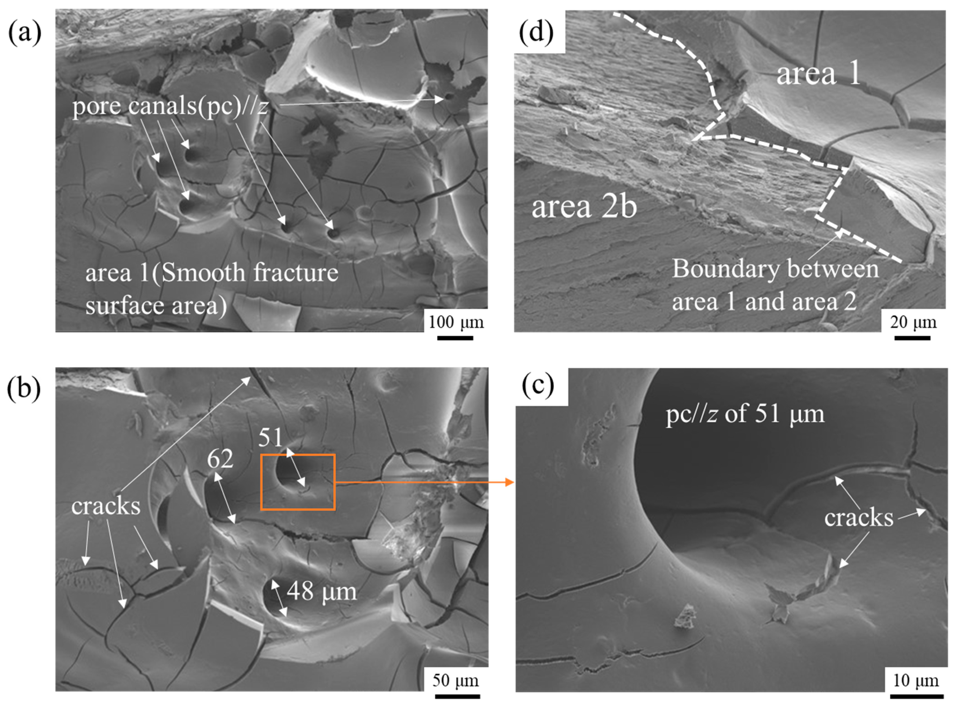
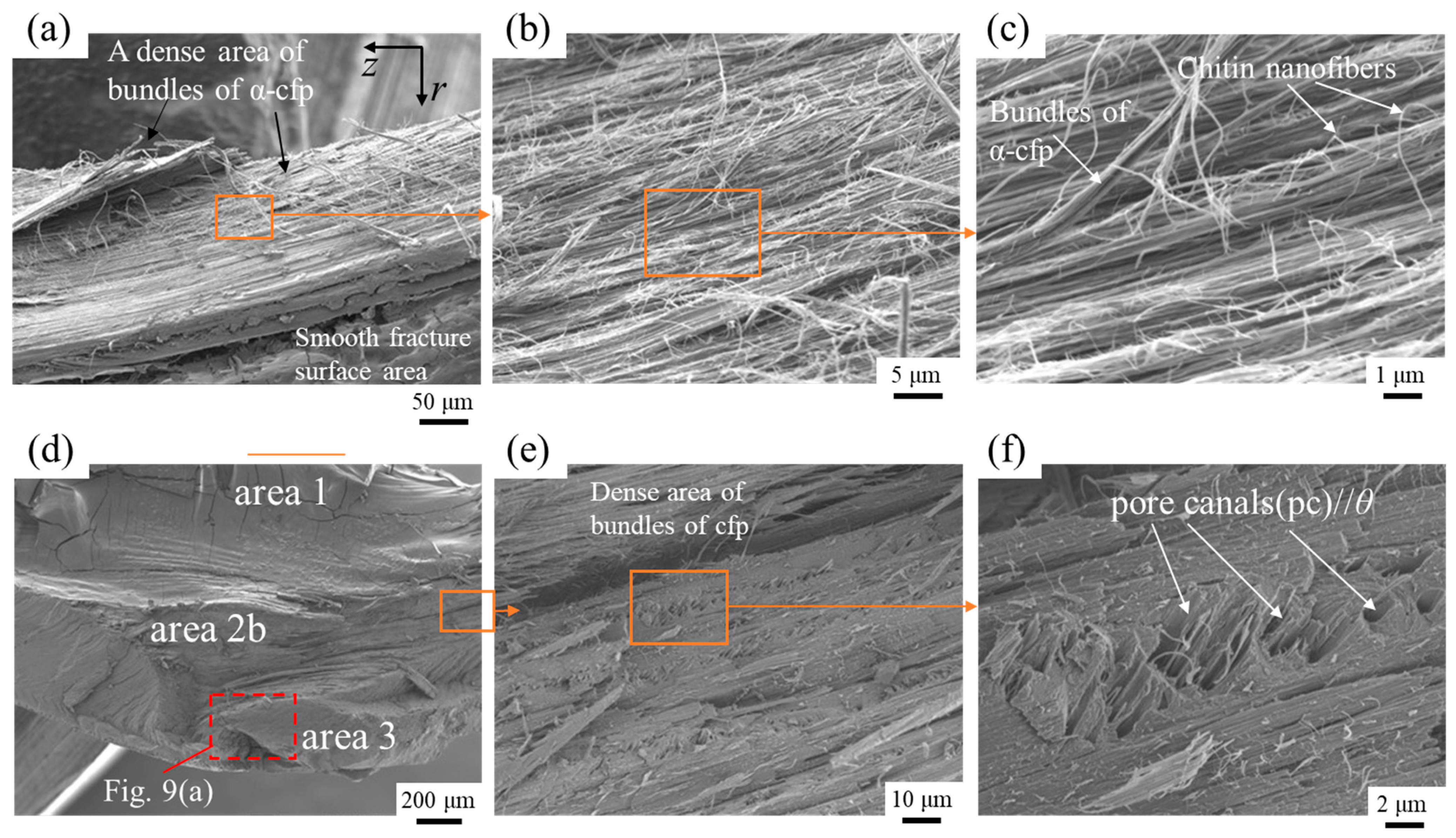
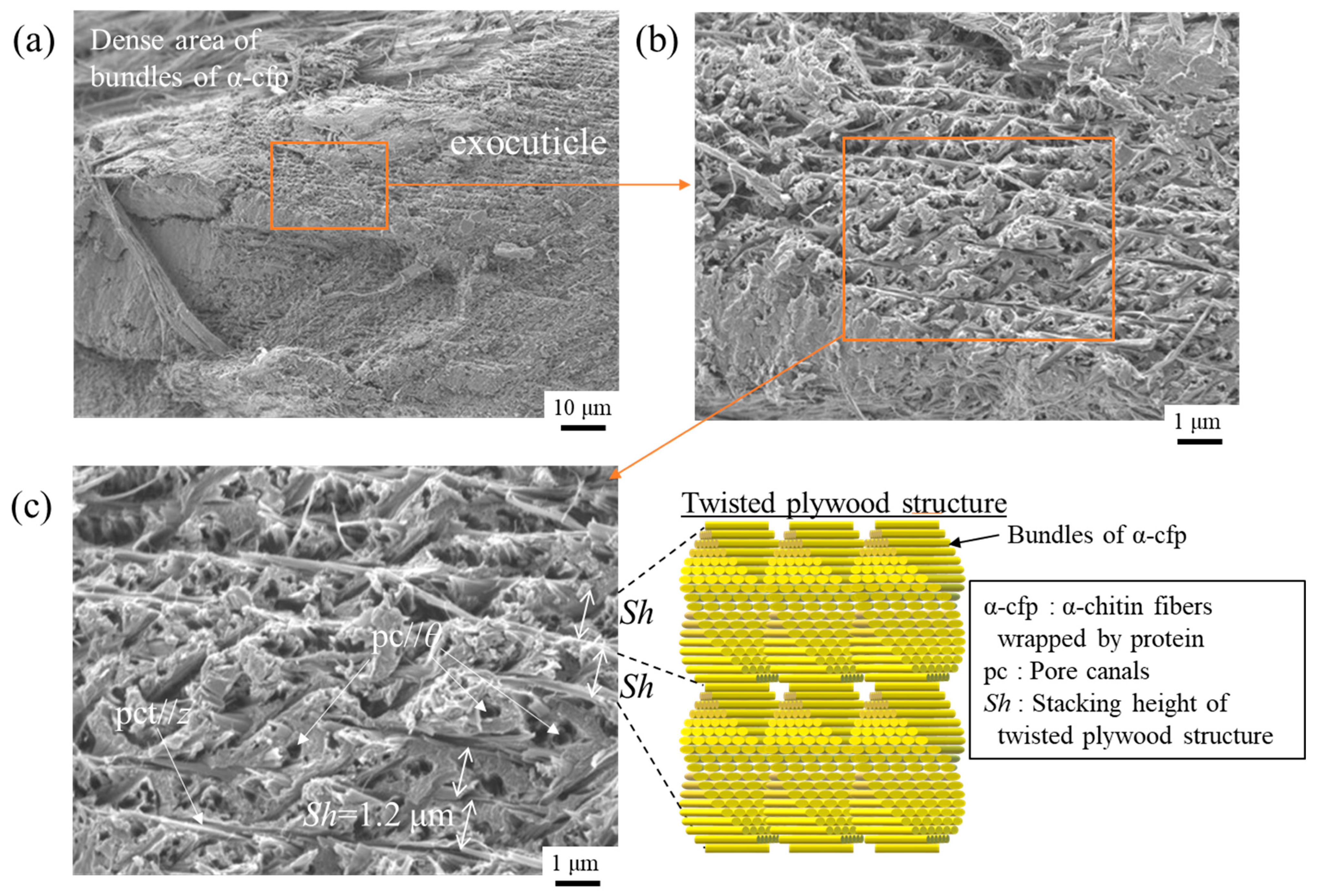
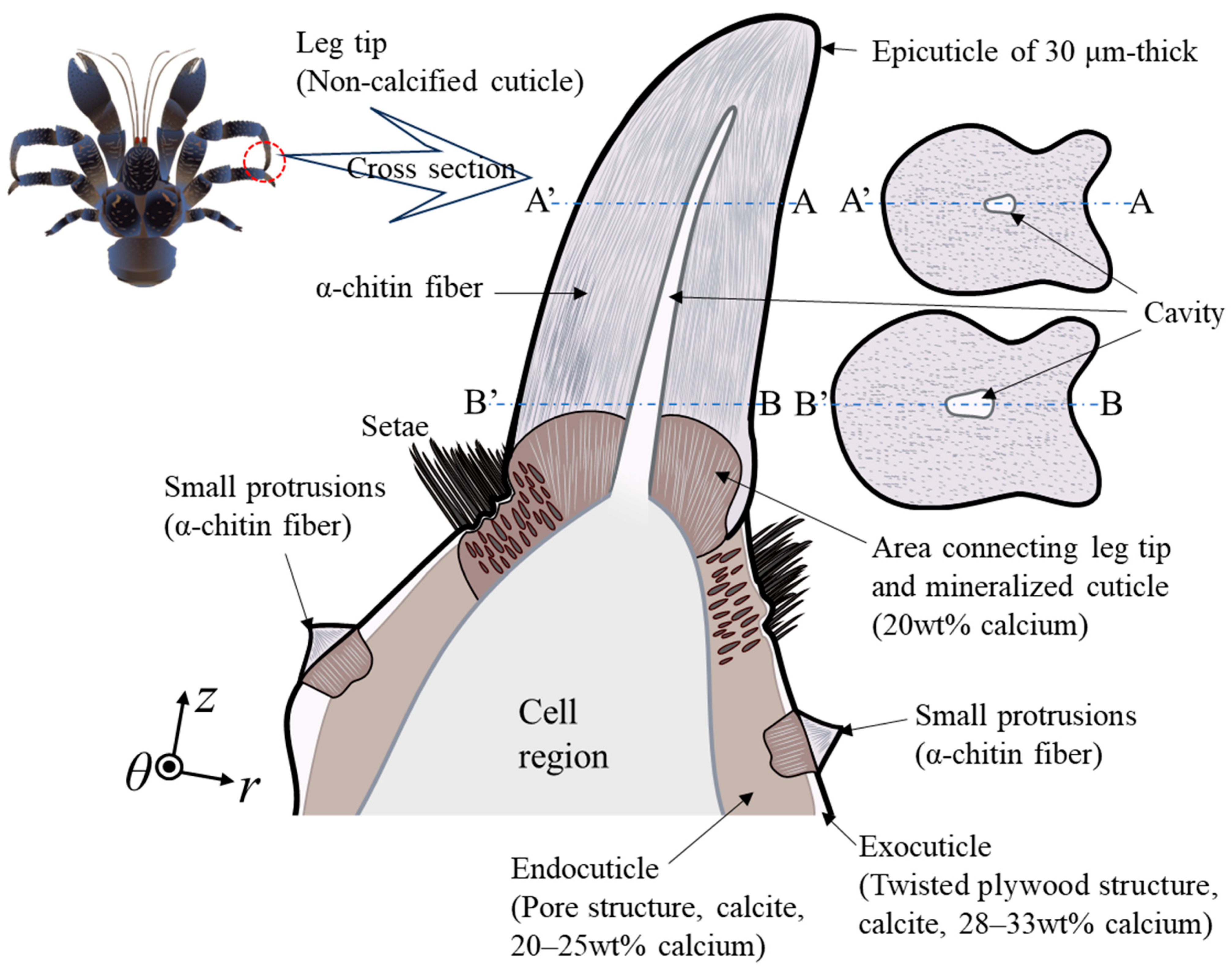
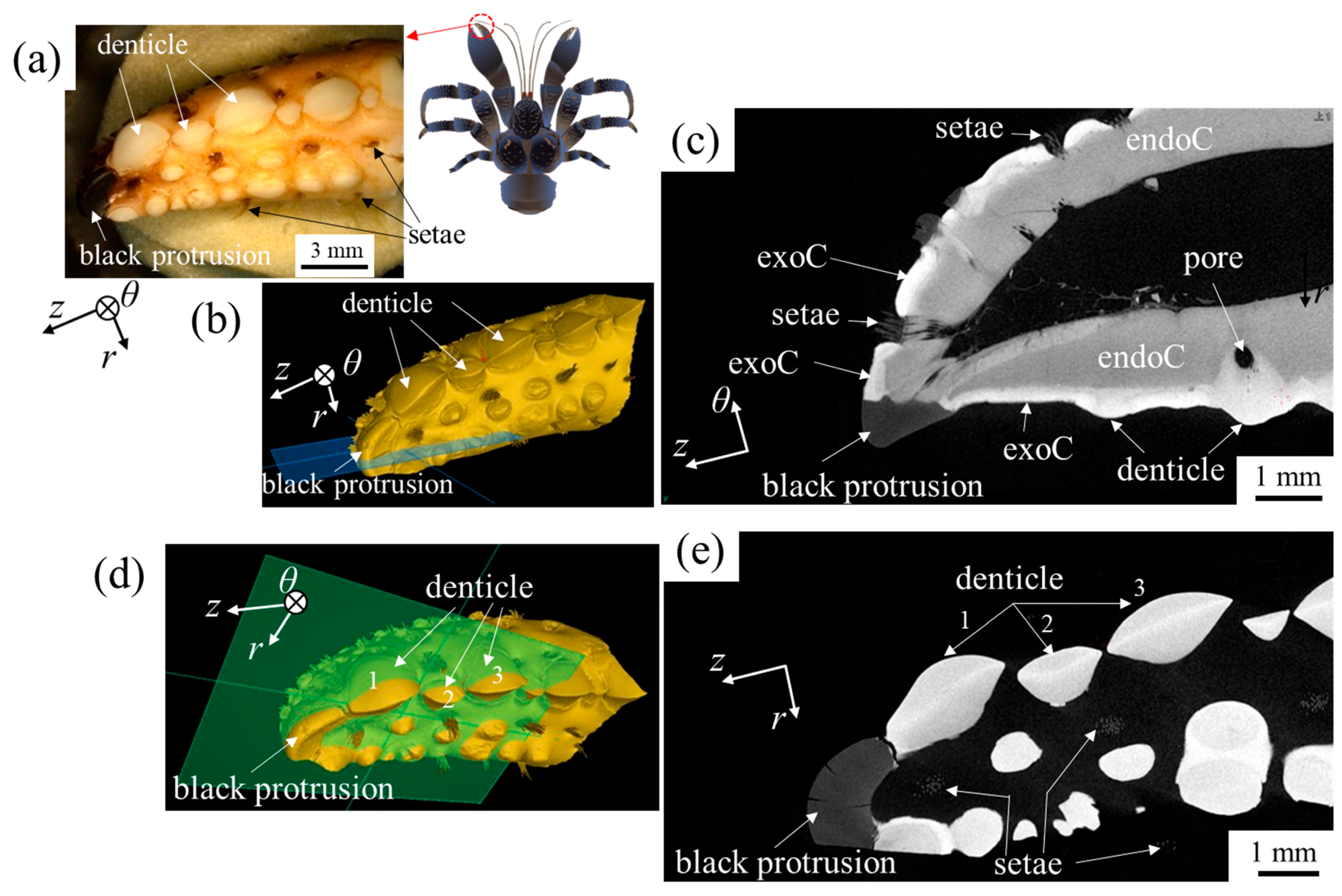
3.3. Microstructures

Since it was not possible to clarify the microstructures of the leg tip on the polished surface, we attempted to observe them through the fractured surface via SEM. The 2WL tip was broken into two pieces (pieces 1 and 2) at the longitudinal center, and then piece 2 was broken again at the center of the cross section (Figure 6a). Piece 1 is a sample for observing the fracture surface of the r-θ plane, and piece 2 is the sample for observing the fracture surface of the r-z plane.
Figure 6b shows the SEM image of the cross section of piece 1. Interestingly, a large cavity was observed in the center of the cross section. The microstructure has a featureless uneven fracture surface (Figure 6d) and a 35 μm thick microstructure (a columnar fracture surface perpendicular to the surface) corresponding to the epicuticle was observed on the outermost surface (Figure 6c). Although different coconut crabs were used for the polished and fractured surfaces, the central cavity and epicuticle thickness of sample B are consistent with those observed on the polished surface of sample A, as shown in Figure 2a and Figure 3a. The cross section of piece 2 is shown in Figure 6e. From this SEM image, the microstructures could be classified into three types: areas 1, 2a and 2b, and 3. Area 1, located in the center of the cross section, had a smooth fracture surface. Around it, in areas 2a and 2b, a fibrous microstructure parallel to the z-direction was observed. Below area 2b was area 3, which had a different microstructure than the other areas.
Figure 7a–c show high-magnification SEM images of area 1. The smooth fracture surface has pores with diameters of 48–62 μm parallel to the z or θ direction and many microcracks throughout the fracture surface. The microcracks seen throughout the smooth fracture surface are caused by drying. Since the microstructure has no specific orientation or anisotropy, the microcracks have no orientation and are distributed throughout the fracture surface. There is no fibrous tissue in this area. Figure 7d is an enlarged micrograph observed in the lower portion of area 1 in Figure 6e. This micrograph shows the boundary (white dashed line) between a smooth fracture surface (area 1) and a fracture surface with the bundles of the α-chitin fibers wrapped by protein (α-cfp) (area 2b). It is also noted that the smooth fracture surface has a certain thickness.
Figure 8 shows high-magnification SEM images of areas 2a and 2b. These areas exist around the pct//z at the center of the black protrusion and correspond to a dense area of bundles of α-cfp. Figure 8a–c reveal that this area consists of a fibrous microstructure parallel to the z direction. In area 2b shown in Figure 8d–f, pore canals perpendicular to the r-z cross section, pc//θ, are observed in the dense area of bundles of α-cfp. The enlarged view bordered by a red rectangle in Figure 8d is displayed in Figure 9a. The SEM images in Figure 9 show that area 3 consists of a twisted plywood pattern structure with a stacking height of Sh = 1.2 μm. This structure appears in the exocuticle on the surface layer of the coconut crab exoskeleton [16]. In short, area 3 is an exocuticle layer.

4. Discussion

4.1. The Black Protrusion and Small Black Protrusion

The hardness results showed that the leg tip was much softer than the mineralized cuticle, with little variation. The hardness of the leg tip was 11–12% of that of the hard exocuticle and 55–57% of that of the soft endocuticle, regardless of the testing method. The elastic modulus of 8.0 GPa that was measured by means of nanoindentation is consistent with that of 8.6–8.8 GPa in a tensile test of α-chitin fibers extracted from shrimp shells [34,35]. The EDS results showed that the leg tip was composed only of organic substances, and the XRD results showed that the leg tip was α-chitin. In other words, the black protrusion on the tip of the second leg of the coconut crab is a non-calcified fibrous tissue of α-chitin connected to the mineralized cuticle.
In the center of the leg tip, a cavity was found to extend from the cell toward the tip (Figure 2a and Figure 6b,e). This appears to taper from the base to the tip. If area 1 in the fracture surface image shown in Figure 6e corresponds to the cross section of the cavity, it indicates that its diameter is 1 mm or more. This is much larger than the size of normal crustacean pcts [1,6,16,21,22,24,25,28,29,36]. However, it is also possible that this cavity was caused by the effects of sample preparation, from freezing to drying. Therefore, we caught live coconut crabs in Okinawa, extracted the black protrusions of the left and right 2WLs, and confirmed the presence or absence of a cavity using a digital microscope (VHX-900; Keyence Corporation, Osaka, Japan).
The results are shown in Figure 10. It was found that the black protrusion was curved, the tip had a radius of the curvature, ρ, of about 0.34 mm, and its cross section was concave at the bottom (Figure 10a–c,g). The cutting planes in Figure 10d,h clearly show the presence of a cavity. The cavity was confirmed in the black protrusions on the left and right sides, and the cavity was oval rather than round. The oval cavity had a long axis above and below the black protrusion and a short axis on the left and right sides of that. When we measured the cavity in the black protrusion on the left side using the software installed in the VHX-900, the major axis was 0.5 mm long, and the minor axis was 0.2 mm long. These lengths correspond to 28% and 13% of the cross-sectional length of the black protrusion, respectively. The cavity was much larger than the pct (100–350 nm) observed in the exoskeleton of the coconut crab [16]. A schematic illustration of the black protrusion at the tip of the walking leg is shown in Figure 11.
As shown in Figure 1c–e and Figure S1, the black protrusion is found not only on the tips of the walking legs, but also on the tips of the claw fingers and on the exoskeleton surfaces of the finger, palm, and carpus of the claws and of the dactyl, propodus, and carpus of the walking legs. All of these black protrusions are thought to be organic substances consisting of the same α-chitin. However, since these black protrusions are smaller than those of the walking leg tips, it was difficult to perform XRD analysis. Therefore, we attempted to obtain a tomographic image of the wider area including the tip of the claw finger and the small black protrusions on the surface of the exoskeleton using microfocus X-ray computed tomography (X-CT). Beam-like samples were fixed in a holder and scanned using a microfocus X-ray CT (XT H 320; NIKON SOLUTIONS Co., Ltd., Tokyo, Japan). A high-resolution scan with a pixel size of 8.4 µm was carried out at 100 kV and 120 µA, and 1500 projections were acquired. Three-dimensional and cross-sectional images were obtained with VGSTUDIO MAX and myVGL 3.5 software (Volume Graphics Co., Ltd., Nagoya, Japan). In a tomographic image, regions of exocuticles and denticles are shown in white, reflecting a high Ca concentration, and gray indicates endocuticles with a lower Ca concentration than the other regions. The results in Figure 12 and Figure 13 show that the claw tip and the small protrusions on the exoskeleton surface are all black, indicating that they are non-calcified cuticles.

4.2. Role of Black Protrusions

As mentioned above, there are soft black protrusions of α-chitin on the tips of the claw fingers and walking legs, and regularly aligned small black protrusions can be seen on the surfaces of the finger, palm, and carpus of the claws and of the dactyl, propodus, and carpus of the walking legs. Considering that the coconut crab is the largest terrestrial crustacean, there seems to be a potential relationship between the presence of these black protrusions and their unique ecological aspects.
The elongated and pointed shape of the black protrusions on the tips of its walking legs allows the coconut crab to frequently engage in vertical movements, such as climbing trees to feed on fruits and seeking shelter in caves, despite its heavy body. This capability is facilitated by its remarkable strength, capable of lifting weights as heavy as 28 kg [14,37] and generating a pinching force nearly 90 times its body weight [17]. Moreover, the soft and flexible black protrusions on the tips of its walking legs provide a secure grip on the surfaces of trees or rocks, preventing slipping during these vertical movements.
The black protrusions on the fingertips of the claws, which appear to have no relation to normal walking or climbing behavior, have a distinct spatula-like shape (Figure 1e and Figure S1). As mentioned earlier, when an extremely strong pinching force is generated, the tips of the claws undergo significant stress. The black protrusions on the fingertips of the claws may serve to alleviate direct pressure on the carapace surface, potentially preventing damage. In fact, the spatula-like shape is designed to distribute force over a broader contact area, avoiding the concentration of intense pressure at a single point.
In addition to the two types of black protrusions mentioned above, it is noteworthy that small spike-like protrusions are scattered on the outer surface of the claws and the most distal joints of the walking legs. The coconut crab inhabits limestone caves and self-dug burrows as its shelter [14,38]. In addition to the pointed protrusions on the tips of the walking legs, these flexible small protrusions around them are believed to provide an advantageous grip for entering and exiting such habitats. Moreover, when the coconut crab senses danger, it rapidly retreats by pushing the ground with both claws, a movement faster than normal walking [39]. This method of movement is not observed in other crustaceans. The fine protrusions on the surface of the claws are distributed only on the outer side of the claws, which serve as the ground contact area during this type of movement. This distribution suggests that these protrusions contribute to rapid movement by providing a strong grip and generating significant rebound force when the claws push against the ground.
Consequently, the black protrusion present on the tips of the walking legs and claws of the coconut crab and the small black protrusions on the surface of the exoskeleton are soft α-chitin, which is significantly different from the tissue and structure of the hard calcite exoskeleton. The cuticles of the coconut crab are designed with the necessary features in the necessary place in relation to its ecology.

Supplementary Materials

The following supporting information can be downloaded at: https://www.mdpi.com/article/10.3390/jmse12040639/s1, Figure S1: (a) Left claw of the coconut crab (sample A: body weight: 1070 g). Claw tip (body weight: 340 g); (b) back; and (c) movable finger side of the other coconut crab; Figure S2: X-ray diffraction (XRD) patterns of the black protrusion (near the center and near the surface) of the right second walking leg tip of the male coconut crab (body weight (BW) 1070 g and thoracic length (ThL) 62 mm), including X-ray diffraction of the α-chitin powders (Reference [31] in main text) and the exocuticle, endocuticle, and denticle of the claw of the male coconut crab (BW: 610 g; ThL: 44.5 mm), including the standard XRD of the calcite crystal (wako; FUJIFILM Wako Pure Chemical Corp., Osaka, Japan) (Reference [19] in main text). Here, XRD analysis was performed using a commercial X-ray diffractometer (SmartLab; Rigaku Co. Ltd., Tokyo, Japan).

Author Contributions

Conceptualization, T.I.; methodology, T.I.; software, T.I.; validation, T.I.; formal analysis, T.I.; investigation, T.I. and S.-i.O.; resources, T.I. and S.-i.O.; data curation, T.I. and T.H.; writing—original draft preparation, T.I., S.-i.O. and T.H.; writing—review and editing, T.I.; visualization, T.I.; supervision, T.I.; project administration, T.I.; funding acquisition, T.I. All authors have read and agreed to the published version of the manuscript.

Funding

This research was funded by JSPS KAKENHI, grant number JP21H04537. The APC was funded by the National Institute for Materials Science.

Institutional Review Board Statement

This study did not require ethical approval.

Informed Consent Statement

Not applicable.

Data Availability Statement

Data are contained within this article.

Acknowledgments

We would like to thank K. Nakazato and Y. Hara for supporting the microstructural observation, M. Sakano for supporting the mechanical tests, and Y. Kashihara for creating the illustrations. T. Tomita and K. Miyamoto (Okinawa Churashima Foundation) contributed valuable ecological insights that significantly enhanced the discussion.

Conflicts of Interest

The authors declare no conflicts of interest. The funders had no role in the design of the study; in the collection, analyses, or interpretation of data; in the writing of the manuscript; or in the decision to publish the results.

References

  1. Bai, L.; Liu, L.; Esquivel, M.; Tardy, B.L.; Huan, S.; Niu, X.; Liu, S.; Yang, G.; Fan, Y.; Rojas, O.J. Nanochitin: Chemistry, structure, assembly, and applications. Chem. Rev. 2022, 122, 11604–11674. [Google Scholar] [CrossRef] [PubMed]
  2. Natarajan, B.; Gilman, J.W. Bioinspired Bouligand cellulose nanocrystal composites: A review of mechanical properties. Philos. Trans. R. Soc. A 2017, 376, 20170050. [Google Scholar] [CrossRef] [PubMed]
  3. Bhushan, B. Biomimetics: Lessons from nature—An overview. Philos. Trans. R. Soc. A 2009, 367, 1445–1486. [Google Scholar] [CrossRef] [PubMed]
  4. Amorim, L.; Santos, A.; Nunes, J.P.; Viana, J.C. Bioinspired approaches for toughening of fibre reinforced polymer composites. Mater. Des. 2021, 199, 109336. [Google Scholar] [CrossRef]
  5. Zhang, B.; Han, Q.; Zhang, J.; Han, Z.; Niu, S.; Ren, L. Advanced bio-inspired structural materials: Local properties determine overall performance. Mater. Today 2020, 41, 177–199. [Google Scholar] [CrossRef]
  6. Zhou, F.; Wu, Z.; Wang, M.; Chen, K. Structure and mechanical properties of pincers of lobster (Procambarus clarkii) and crab (Eriocheir Sinensis). J. Mech. Behav. Biomed. Mater. 2010, 3, 454–463. [Google Scholar] [CrossRef] [PubMed]
  7. Bouligand, Y. Twisted fibrous arrangements in biological materials and cholesteric mesophases. Tissue Cell 1972, 4, 189–217. [Google Scholar] [CrossRef] [PubMed]
  8. Wu, K.; Song, Z.; Zhang, S.; Ni, Y.; Cai, S.; Gong, X.; He, L.; Yu, S. Discontinuous fibrous Bouligand architecture enabling formidable fracture resistance with crack orientation insensitivity. Proc. Natl. Acad. Sci. USA 2020, 117, 15465–15472. [Google Scholar] [CrossRef] [PubMed]
  9. Chen, Q.; Pugno, N.M. Bio-mimetic mechanisms of natural hierarchical materials: A review. J. Mech. Behav. Biomed. Mater. 2013, 19, 3–33. [Google Scholar] [CrossRef]
  10. Yamagata, N.; Randall, G.; Lavoie, E.; Arola, D.; Wang, J. Microstructure, mechanical properties and elemental composition of the terrestrial isopod Armadillidium vulgare cuticle. J. Mech. Behav. Biomed. Mater. 2022, 132, 105299. [Google Scholar] [CrossRef]
  11. Ma, Y.; Guo, C.; Dai, N.; Shen, J.; Guan, J. Structural characterization and regulation of the mechanical properties of the carapace cuticle in tri-spine horseshoe crab (Tachypleus tridentatus). J. Mech. Behav. Biomed. Mater. 2022, 125, 104954. [Google Scholar] [CrossRef]
  12. Kundanati, L.; Signetti, S.; Gupta, H.S.; Menegon, M.; Pugno, N.M. Multilayer stag beetle elytra perform better under external loading via nonsymmetric bending properties. J. R. Soc. Interface 2018, 15, 20180427. [Google Scholar] [CrossRef]
  13. Tan, T.; Ribbans, B. A bioinspired study on the compressive resistance of helicoidal fibre structures. Proc. R. Soc. A 2017, 473, 20170538. [Google Scholar] [CrossRef]
  14. Drew, M.M.; Harzsch, S.; Stensmyr, M.; Erland, S.; Hansson, B.S. A review of the biology and ecology of the Robber Crab, Birgus latro (Linnaeus, 1767) (Anomura: Coenobitidae). Zoo. Anz. 2010, 249, 45–67. [Google Scholar] [CrossRef]
  15. Cumberlidge, N. Birgus latro. In The IUCN Red List of Threatened Species 2020; International Union for Conservation of Nature and Natural Resources: Gland, Switzerland, 2020; Available online: https://doi.org/10.2305/IUCN.UK.2020-2.RLTS.T2811A126813586.en (accessed on 4 April 2024).
  16. Inoue, T.; Oka, S.; Hara, T. Three-dimensional microstructure of robust claw of coconut crab, one of the largest terrestrial crustaceans. Mater. Des. 2021, 206, 109765. [Google Scholar] [CrossRef]
  17. Oka, T.; Tomita, K.; Miyamoto, A. Mighty Claw: Pinching Force of the Coconut Crab, the Largest Terrestrial Crustacean. PLoS ONE 2016, 11, e0166108. [Google Scholar] [CrossRef]
  18. Inoue, T.; Hara, T.; Nakazato, K.; Oka, S. Superior mechanical resistance in the exoskeleton of the coconut crab, Birgus latro. Mater. Today Bio 2021, 12, 100132. [Google Scholar] [CrossRef]
  19. Inoue, T.; Oka, S.; Nakazato, K.; Hara, T. Columnar structure of claw denticles in the coconut crab, Birgus latro. Minerals 2022, 12, 274. [Google Scholar] [CrossRef]
  20. Inoue, T.; Oka, S.; Nakazato, K.; Hara, T. Structural changes and mechanical resistance of claws and denticles in coconut crabs of different sizes. Biology 2021, 10, 1304. [Google Scholar] [CrossRef]
  21. Oliver, W.C.; Pharr, G.M. An improved technique for determining hardness and elastic modulus using load and displacement sensing indentation experiments. J. Mater. Res. 1992, 7, 1564–1583. [Google Scholar] [CrossRef]
  22. Inoue, T.; Hiroto, T.; Hara, Y.; Nakazato, K.; Oka, S. Tissue structure and mechanical properties of the exoskeleton of the huge claws of the mud crab, Scylla serrata. J. Mater. Sci. 2023, 58, 1099–1115. [Google Scholar] [CrossRef]
  23. Vittori, M.; Srot, V.; Korat, L.; Rejec, M.; Sedmak, P.; Bussmann, B.; Predel, F.; Aken, P.A.; Štrus, J. The mechanical consequences of the interplay of mineral distribution and organic matrix orientation in the claws of the sea slater Ligia pallasii. Minerals 2021, 11, 1373. [Google Scholar] [CrossRef]
  24. Fabritius, H.-O.; Karsten, E.S.; Balasundaram, K.; Hild, S.; Huemer, K.; Raabe, D. Correlation of structure, composition and local mechanical properties in the dorsal carapace of the edible crab Cancer pagurus. Z. Krist. 2012, 227, 766–776. [Google Scholar] [CrossRef]
  25. Sachs, C.; Fabritius, H.; Raabe, D. Hardness and elastic properties of dehydrated cuticle from the lobster Homarus americanus obtained by nanoindentation. J. Mater. Res. 2006, 21, 1987–1995. [Google Scholar] [CrossRef]
  26. Kellersztein, I.; Cohen, S.R.; Bar-On, B.; Wagner, H.D. The exoskeleton of scorpions’ pincers: Structure and micro-mechanical properties. Acta Biomater. 2019, 94, 565–573. [Google Scholar] [CrossRef] [PubMed]
  27. Cribb, B.W.; Rathmell, A.; Charters, R.; Rasch, R.; Huang, H.; Tibbetts, I.R. Structure, composition and properties of naturally occurring non-calcified crustacean cuticle. Arthropod Struct. Dev. 2009, 38, 173–178. [Google Scholar] [CrossRef] [PubMed]
  28. Rose, R.; Dillaman, R. The structure and calcification of the crustacean cuticle. Am. Zool. 1984, 24, 893–909. [Google Scholar] [CrossRef]
  29. Yano, I. A histochemical study on the exocuticle with respect to its calcification and associated epidermal cells in a shore crab. Bull. Jpn. Soc. Sci. Fish 1972, 38, 733–739. [Google Scholar] [CrossRef]
  30. Qian, Z.; Yang, M.; Zhou, L.; Liu, J.; Akhtar, R.; Liu, C.; Liu, Y.; Ren, L.; Ren, L. Structure, mechanical properties and surface morphology of the snapping shrimp claw. J. Mater. Sci. 2018, 53, 10666–10678. [Google Scholar] [CrossRef]
  31. Zhang, Y.; Jiang, J.; Liu, L.; Zheng, K.; Yu, S.; Fan, Y. Preparation, assessment, and comparison of α-chitin nano-fiber films with different surface charges. Nanoscale Res. Lett. 2015, 10, 226. [Google Scholar] [CrossRef]
  32. Boßelmann, F.; Romano, P.; Fabritius, H.; Raabe, D.; Epple, M. The composition of the exoskeleton of two crustacea: The American lobster Homarus americanus and the edible crab Cancer pagurus. Thermochim. Acta 2007, 463, 65–68. [Google Scholar] [CrossRef]
  33. Schofield, R.M.S.; Niedbala, J.C.; Nesson, M.H.; Tao, Y.; Shokes, J.E.; Scott, R.A.; Latimer, M.J. Br-rich tips of calcified crab claws are less hard but more fracture resistant: A comparison of mineralized and heavy-element biological materials. J. Struct. Biol. 2009, 166, 272–287. [Google Scholar] [CrossRef] [PubMed]
  34. Qin, Y.; Lu, X.; Sun, N.; Rogers, R. Dissolution or extraction of crustacean shells using ionic liquids to obtain high molecular weight purified chitin and direct production of chitin films and fibers. Green Chem. 2010, 12, 968–971. [Google Scholar] [CrossRef]
  35. Shamshina, J.L.; Gurau, G.; Block, L.E.; Hansen, L.K.; Dingee, C.; Walters, A.; Rogers, R.D. Chitin–calcium alginate composite fibers for wound care dressings spun from ionic liquid solution. J. Mater. Chem. B 2014, 2, 3924–3936. [Google Scholar] [CrossRef] [PubMed]
  36. Nekvapil, F.; Pinzaru, S.C.; Barbu–Tudoran, L.; Suciu, M.; Glamuzina, B.; Tamas, T.; Chis, V. Color-specific porosity in double pigmented natural 3D-nanoarchitectures of blue crab shell. Sci. Rep. 2020, 10, 3019. [Google Scholar] [CrossRef] [PubMed]
  37. Altevogt, R.; Davis, T.A. B Birgus latro, India’s monstrous crab. A study and an appeal. Bull. Dep. Mar. Sci. Univ. Cochin 1975, 7, 11–24. [Google Scholar]
  38. Oka, S.; Matsuzaki, S.; Miyamoto, K. Current status of the coconut crab, Birgus latro (Anomura: Coenobitidae) in Ocean Expo Park, Okinawa-jima Island, southwestern Japan. Biol. Mag. Okinawa 2014, 52, 11–19, (In Japanese with English abstract). [Google Scholar]
  39. Helfman, G.S. Agonistic behavior of the coconut crab, Birgus latro (L.). Z. Tierpsychol. 1977, 43, 425–438. [Google Scholar] [CrossRef]
Figure 1. (a) Top and (b) bottom of the coconut crab, Birgus latro (sample B; body weight = 964 g and thoracic length = 53.5 mm), and enlarged images of (c,d) the right second walking leg tip and (e) the movable finger tip of the right claw. Here, in (a,b), the right claw (*) was used for videography in another study (https://www.nims.go.jp/eng/publicity/digital/movie/mov202202070.html accessed on 4 April 2024).
Jmse 12 00639 g001
Figure 3. (a) OM image of the leg tip cross section after nanoindentation testing. Distributions of (b) hardness, HIT, and (c) elastic modulus, Er, with the distance from the outer surface, r, on Lines 1 and 2. Here, H(epo) and Er(epo) denote the hardness and elastic modulus of the cold epoxy resin, respectively.
Jmse 12 00639 g003
Figure 4. X-ray diffraction (XRD) patterns of the black protusion, including X-ray diffraction of the α-chitin powders [31] and the cold epoxy resin used in the present study. Here, XRD analysis at five positions for the center and surface was performed.
Jmse 12 00639 g004
Figure 5. (a) SEM image near the black protrusion top and an X-ray spectrum showing the presence of C, O, Cl, and Al or Br in the area surrounded by the rectangle in the image, and (b) EDS map showing the distribution of C; (c) SEM image near the area between the black protrusion and cuticle and an X-ray spectrum showing the presence of C, O, Cl, Ca, Mg, P, Na, S, and Al or Br in area 1 and area 2 surrounded by the rectangle in the image; (d) EDS maps showing the distribution of C, Ca, Mg, and P. Here, the Al is the residue from the alumina used in the polishing.
Jmse 12 00639 g005
Figure 6. The second walking leg tip of sample B. (a) Two test pieces of the leg tip after fracture; (b) SEM images of the r-θ fracture surface in piece 1 and (c,d) enlarged views of areas surrounded by rectangles in (b); (e) SEM images of the r-z fracture surface in piece 2.
Jmse 12 00639 g006
Figure 7. SEM images of the r-z fracture surface corresponding to area 1 in piece 2: (a) smooth fracture surface including some pore canals (pcs); (b) enlarged view near pcs; (c) enlarged view surrounded by rectangles in (b); (d) near the boundary between the area 1 and the area 2b.
Jmse 12 00639 g007
Figure 8. (a) SEM image near the outer surface of area 2a shown in Figure 6e and (b,c) enlarged views of the bundles of cp; (d) SEM image of the r-z fracture surface near areas 2b and 3; (e) high-magnification SEM image of a dense area of bundles of cp; and (f) enlarged view bordered by rectangles in (e). Here, cp denotes chitin fiber wrapped by protein.
Jmse 12 00639 g008
Figure 9. SEM images of the r-z fracture surface corresponding to area 3 shown in Figure 6e: (a) smooth fracture surface including some pore canals (pcs); (b) enlarged view near the pcs; (c) enlarged view surrounded by rectangles in (b).
Jmse 12 00639 g009
Figure 10. The black protrusions of the top of the (ae) left and (fh) right second walking legs of the coconut crab, Birgus latro. Left side: (ac) longitudinal images; (d) image of transverse cross section (cutting plane); and (e) image from the top. Right side: (f) image from the top; (g) longitudinal image; and (h) image of the transverse cross section (cutting plane). Two samples were obtained by cutting the tip of the black protrusion of a live coconut crab (male, body weight: 910 g) with nippers. Here, r denotes the curvature radius.
Jmse 12 00639 g010
Figure 11. Cross-sectional schematic illustration near the top of the second walking leg in the coconut crab.
Jmse 12 00639 g011
Figure 12. (a) The movable fingertip of the left claw in the coconut crab (body weight: 300 g); (b,d) tomographic reconstructions of its fingertip; (c) ortho-slice view of the z-θ plane showed in (b); and (e) ortho-slice view of the r-z plane shown in (d). The X-ray CT images shown in (c,e) show that the calcium concentration increases as the color becomes whiter.
Jmse 12 00639 g012
Figure 13. (a) Part of the movable finger of the left claw in the coconut crab (body weight: 1650 g); (b,d) tomographic reconstructions of its fingertip; (c) ortho-slice view of the z-θ plane shown in (b); and (e) ortho-slice view of the r-z plane shown in (d). The X-ray CT images shown in (c,e) show that the calcium concentration increases as the color becomes whiter.
Jmse 12 00639 g013
Disclaimer/Publisher’s Note: The statements, opinions and data contained in all publications are solely those of the individual author(s) and contributor(s) and not of MDPI and/or the editor(s). MDPI and/or the editor(s) disclaim responsibility for any injury to people or property resulting from any ideas, methods, instructions or products referred to in the content.

