Article

Exploration of the Pulsation Characteristics of a Bubble Adjacent to the Structure with Multiple Air Bubble Adhesions

1
College of Automation, Jiangsu University of Science and Technology, Zhenjiang 212003, China
2
School of Naval Architecture and Ocean Engineering, Jiangsu University of Science and Technology, Zhenjiang 212003, China
*
Author to whom correspondence should be addressed.
J. Mar. Sci. Eng. 2024, 12(9), 1631; https://doi.org/10.3390/jmse12091631
Submission received: 12 August 2024 / Revised: 5 September 2024 / Accepted: 9 September 2024 / Published: 12 September 2024

Abstract

:
The dynamics of bubbles have garnered extensive interest among researchers both domestically and internationally due to their applications in engineering and military fields. The exploration of the mechanisms behind bubble loading, cavitation damage, and impact destruction has always been a focal point of study. However, in practical applications, bubbles often do not occur in isolation, and the interactions between multiple bubbles are highly complex. Therefore, this study investigates the pulsation characteristics of bubbles near rigid boundaries with multiple air bubbles attached in different spatial arrangements, focusing on the coupled pulsation phenomenon between cavitation clusters and bubbles. The research indicates that this coupled pulsation phenomenon is primarily influenced by the dimensionless distance parameter γs from the bubble to the boundary, the spacing γL between the air bubbles, and the spatial arrangement. Compared to Layout II, the bubble exhibits off-axis migration and jet direction only under Layout I conditions; for spatial Layout I, when the air bubble spacing γL is fixed, the displacement of the air bubble directly above the bubble is proportional to the distance parameter γs. This research underscores the potential for mitigating cavitation-induced damage through the strategic adhesion of multiple air bubbles.

1. Introduction

The applications of bubble dynamics in practical engineering have sparked widespread interest in the field of bubbles. The exploration of the mechanisms of bubble load and cavitation damage has always been a focal point of research. However, in practical applications, bubbles often do not appear alone, as seen in cavitation cleaning [1,2], bubble drag reduction [3], propeller cavitation bubbles [4,5], and underwater multi-munition explosions [6]. The interactions between multiple bubbles are highly complex. Currently, researchers, both domestically and internationally, focus on the coupling effects between bubbles with different spatial arrangements [7,8], different phases [9,10], and different sizes [11]. When the distance parameter is small, bubble coalescence is more likely to occur. Most of the aforementioned studies focus on the interactions between multiple pulsating bubbles, while in practical applications, interactions between pulsating and non-pulsating bubbles are more common.
Underwater explosion tests are the most effective means to study the pulsation and load characteristics of underwater explosion bubbles, but these tests are costly and difficult to observe. Some researchers conduct small-scale underwater explosion tests, but due to impurities in the explosive charges affecting observation results, these tests are relatively rare. Currently, most researchers mainly use laser pulses or spark-generated bubbles to simulate real explosion bubbles for studying bubble dynamic mechanisms.
In the process of multiple bubble coupling, interactions involve multiple pulsating bubbles as well as the interaction between pulsating bubbles and air bubbles. Multiple underwater explosion bubbles are present in scenarios where multiple bombs are detonated in a short period, mainly involving in-phase multiple bubble coupling and out-of-phase multiple bubble coupling. Timm et al. [12] were the first to experimentally study the interaction of two bubbles. Zhang et al. [13] conducted numerical studies on the interaction of clustered air gun bubbles (2–3 bubbles) in the field of marine resource exploration, examining the impact of bubble distance and volume distribution on far-field pressure waves by considering the topological structure of bubbles during coalescence and splitting. Li et al. [14] carried out experimental and numerical studies on the nonlinear coupling and coalescence characteristics of two in-phase pulsating bubbles and defined three different coalescence modes based on the distance parameter between the two bubbles. Naing et al. [15] experimentally studied the characteristics of two vertically aligned pulsating bubbles near a structural surface, analyzing the parametric effects of the distance parameter between bubbles, the distance between bubbles and the structure, and bubble size.
Xu et al. [16] conducted fundamental research on jet and shock wave phenomena during the interaction process of two pulsating bubbles and analyzing factors such as the relative size and phase difference in the bubbles and pointed out that multiple shock waves can be released in a short period during the interaction of two bubbles. Subsequently, Luo et al. [17] observed the layering effect of shock waves produced by the first collapse of cavitation bubbles under the action of pulsating bubbles, highlighting the importance of the relative distance and scale of the two bubbles in the layering effect. Then, Luo et al. [18] revealed that the number of air bubbles has a greater impact on cavitation erosion mitigation than the total air concentration.
Some scholars conducted in-depth research on various aspects of multibubble coupling through theoretical analysis, numerical simulations, and low-pressure discharge equipment. These aspects include two-bubble coalescence conducted by Li et al. [14], anisotropic dual-bubble coupling Lv et al. [19], multiple bubbles coupling Zhang et al. [20], the pressure wave characteristics of three pulsating bubbles Zhang et al. [13], the bubble collapse pattern near the wall of an adherent gas layer [21], and three linearly arranged spark bubbles with controlled phase differences [22]. Sun [23] studied the influence of the dynamic behavior of a laser-induced bubble near the rigid wall with a gas-containing hole and found that the deflection of the bubble could be controlled. The bubble dynamics in the rectangular channel [24] and funnel-shaped tube [25] have been meticulously studied, with a particular focus on the jetting and migration of the bubble. Additionally, Zhang [26] focused on the dynamic behavior of bubbles under the boundary of an elastic–plastic structure during deep-water explosion, and the bubble motion and jet load characteristics were explored. Tan et al. [27] indicate that the collapse characteristics of bubbles near attached air bubbles show that air bubbles weaken the two main damaging mechanisms of high-speed jets and shock waves from pulsating bubbles. Wu et al. [28] pointed out that for in cavitation erosion reduction, bubbles tend to deflect towards smaller air bubbles upon collapse, making the protective effect of small air bubbles better than that of larger ones. Wei et al. [21] studied the bubble collapse model near the surface of a hydrophobically treated porous copper medium with attached gas layers, highlighting different bubble collapse modes and how central migration has positive significance in reducing cavitation erosion. Wang et al. [29,30] studied the pulsation characteristics of bubbles near attached bubbles on fixed structures, summarizing the characteristics of bubble jet direction and the coupling pulsation characteristics of two bubbles. They proposed criteria for judging the jet of underwater explosion bubbles in the presence of attached air bubbles.
The coupled pulsation phenomena of multiple bubbles (multiple pulsating bubbles, pulsating bubbles, and air bubbles) have broad applications in aeration erosion reduction in high dams, air gun resource exploration, and underwater explosion protection. It was pointed out that air bubbles can change the jet and migration directions of pulsating bubbles to reduce cavitation erosion, with the protective effect related to parameters such as the size and distance of the air bubbles. This manuscript investigated the oscillating bubble pulsation phenomena near multiple air bubbles adhering to the structural surface, analyzing the influence of two types of spatial arrangements between adhering to air bubbles and pulsating bubbles (Layout I and II), and the distance parameters between oscillating bubbles and the structure γs, and inter-air bubble spacing parameters γL. Through the observation of bubble pulsation morphologies and various special bubble-jetting phenomena, this study reveals the strong nonlinear coupling interactions between pulsating bubbles and air bubbles. The results can be utilized in applications to mitigate cavitation-induced damage through the strategic adhesion of multiple air bubbles.

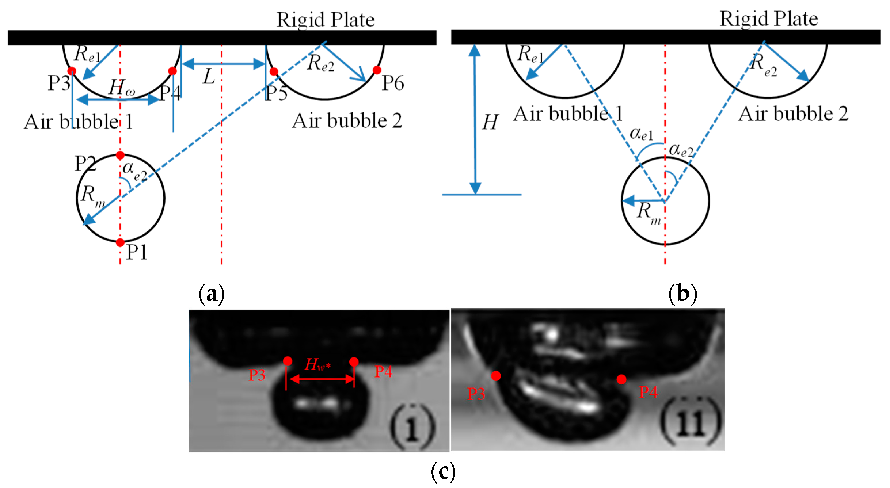
2. Experimental Setup and Methods

The experimental setup used in this study included a low-pressure discharge system, a high-speed camera, an adjustable structure-positioning device, and an illumination light source, among other equipment, as shown in Figure 1. The experiment was conducted in a glass water tank measuring 0.5 m × 0.5 m × 0.5 m. A 220 V AC voltage was converted to DC voltage using a 6600 µF capacitor (with three 2200µF Rubycon capacitors from Ina City, Japan parallel connected), and when the voltage reached approximately 100 V, and discharge was triggered. A thin copper wire with a diameter of 0.25 mm was short-circuited, causing the surrounding liquid to vaporize at high temperatures and produce spark-generated bubbles in the water tank [31]. Under this discharge voltage, the maximum radius of the pulsating bubbles ranged from approximately 3 mm to 6 mm, with the copper wire’s radius being about 2.1% to 4.2% of the maximum bubble radius, making the influence of the copper wire on the bubble dynamics negligible. A high-speed camera, Photron FASTCAM SA-Z from Chiyoda City, Japan was used to record the process through cyclic sampling. To ensure optimal recording quality, a continuous light source with a power of 2 KW was placed on the opposite side of the water tank to provide sufficient brightness for the high-speed camera.
As depicted in Figure 2, there are two types of bubbles. One type is attached to the structural surface and is referred to as an “air bubble”. Specifically, the volume of an air bubble is introduced under the plate using 1.0 mL syringes with a scale of 100. The other type of bubble is the spark-generated bubble and is termed an “oscillating bubble”. To study the interactions between multiple bubbles, the following dimensionless parameters are defined: the dimensionless distance parameter γs between the bubble and the steel plate, the dimensionless spacing parameter γL between attached air bubbles, and the impact of the generation position of the spark-generated bubble. Unlike the motion characteristics of bubbles near a single air bubble attached to a fixed structure surface [32], the movement and migration direction of the bubble, in addition to being influenced by the adjacent air bubble, is also affected by other air bubbles, resulting in non-vertical jet characteristics, such as multibubble, coalescence, apple-shaped bubbles, and reverse deflection jets. To enhance the applicability of the research results, two physical quantities were dimensionless in the analysis process. Additionally, in the images, the air bubble attached to the left below the boundary is defined as bubble 1, and the air bubble attached to the right is bubble 2. The volume of the attached air bubbles is approximately 0.04 mL, and both bubbles can be considered to be regular hemispheres.
The ratio of the distance H from the copper wire junction point to the boundary to the maximum bubble radius Rm is used as the dimensionless measure of distance, denoted as distance parameter γs [24]:
γ s = H R m
The dimensionless spacing parameter of the air bubbles can be defined as follows:
γ L = L R m
Here, H represents the distance from the bubble center to the boundary, Rm denotes the equivalent radius of the spark-generated bubble at its maximum volume, corresponding to the maximum volume Vm; L represents the distance between the centers of air bubble 1 and air bubble 2, and Re1,2 denotes the initial radii of attached air bubbles 1 and 2, corresponding to the initial volumes Ve1,2. The measurement points for all bubbles are arranged as follows: the top and bottom vertices of the bubble are denoted as P1 and P2, respectively; the left and right endpoints at the middle of air bubble 1 are P3 and P4, and the left and right endpoints at the middle of air bubble 2 are P5 and P6.
To facilitate the analysis of the experimental results, the bubble dimensionless pulsation time was defined as follows [32]:
T * = t R m ρ P P c
where t denotes the actual measurement time of the bubble pulsation in the experiment, p denotes the reference pressure at the location of bubble generation, ρ denotes the density of the liquid, and the practical significance of the following equation in the denominator denotes the time scale [33].
The dimensionless volume ratio, V′, is as follows:
V = V m V e 1 f o r l a y e r I V m max V e 1 , V e 2 f o r l a y e r I I
where Vm, Ve1, and Ve2 are the maximum volume of the generated bubble and the initial volume of the two air bubbles, respectively.
Similarly, according to Equations (1) and (2), D* denotes the dimensionless displacement change at the measurement point, and Hw* =Hω/Rm denotes the dimensionless width of the air bubble. The concept of inclination angle αe1 and αe2, i.e., the angle between the initial bubble and the air bubble centroid line and vertical direction, was introduced for layer I, αe1 = 0, αe1 ≠ 0, and for layer II, αe1 ≠ 0, αe1 ≠ 0.
Figure 2. Definition of basic parameters. (a) Layout I: the oscillating bubble is located directly below bubble 1. (b) Layout II: the oscillating bubble is located between two air bubbles. (c) Some typical points on air bubbles for air bubble 1 when αe1 = 0 (i), and air bubble 2 when αe2 ≠ 0 (ii).
Jmse 12 01631 g002

3. Results and Discussion

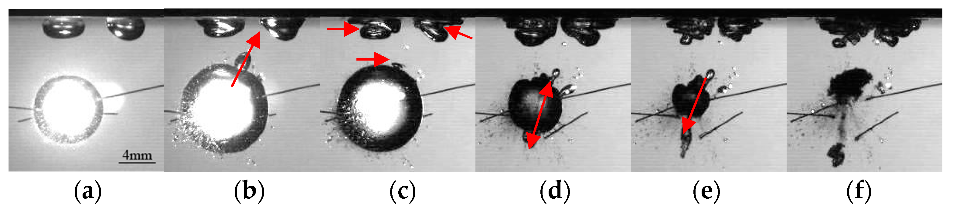
3.1. Layout I: Bubble Movement Characteristics Directly below Unilateral Air Bubble

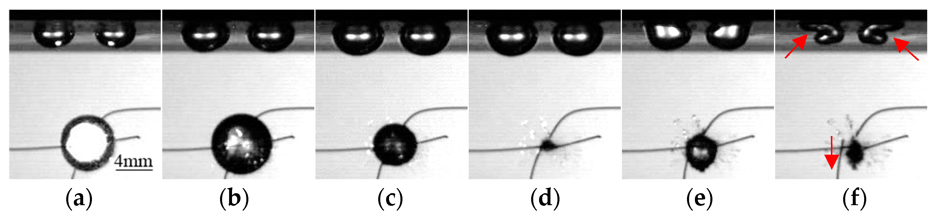
3.1.1. Reverse Jets in an Inclined Direction

Figure 3 shows the coupling pulsation of three bubbles with the dimensionless distance parameter γs =2.63, the initial volumes of attached air bubbles at Ve1 = 0.04 mL and Ve2 = 0.05 mL, and the dimensionless spacing parameter γL = 0.16. The inclination angles between the bubble and the two air bubbles were αe1 = 0° and αe2 = 28°, respectively. Due to the large distance parameter, the bubble initially expands into a fairly regular spherical shape. At 1.26 ms, the bubble reaches its maximum volume Vm = 0.27 mL. The lower surface of air bubble 1 is noticeably flattened due to pressure, while air bubble 2 remains a regular hemisphere with minimal influence. Air bubble 1 is affected by air bubble 2, causing its right side to flatten and tilt to the right, losing its symmetry. At 1.65 ms, the bubble continues to shrink spherically, and the lower right side of air bubble 1 stretches towards air bubble 2. At this time, air bubble 2 is minimally affected by the bubble disturbance and maintains its regular hemispherical shape. In Figure 3d, the bubble contracts to its minimum volume and begins to rebound. Figure 3e shows that the bubble forms a jet directed to the lower left, with significant surface deformation for both air bubbles, especially air bubble 1. The repulsive force from the air bubbles on the bubble is directed downward to the left, resulting in a force on the cavitation of bubbles in the upward right direction. This was primarily due to the vectorial summation of the repulsive forces exerted by the two adhering air bubbles on the oscillating bubble [29]. Consequently, air bubble 1 moved to the right. As the distance between the two air bubbles decreased, they approached each other from the lower surfaces and merged at 2.23 ms. When a bubble was located directly below an air bubble, the bubble jet was directed vertically. However, the presence of air bubble 2 disrupts the spatial symmetry, causing the bubble jet to deviate from the vertical direction.

3.1.2. The Oblique Directional Midsection Splitting

Figure 4 shows the coupling pulsation of three bubbles with a dimensionless distance parameter γs = 2.15, initial volumes of attached air bubbles Ve1 = 0.04 mL and Ve2 = 0.04 mL, inclination angles between the bubble and the two air bubbles αe1 = 0° and αe2 = 31°, and an air bubble spacing parameter γL = 0.42. During the bubble expansion phase, the interaction between the air bubbles is minimal due to the larger spacing between them. Air bubble 1 maintains its hemispherical shape, while the left side of air bubble 2 shows deformation. This process is essentially a combination of the interactions between the bubble and the two air bubbles, as shown in Figure 4a. When the bubble expands to its maximum volume, its upper surface bulges significantly towards air bubble 2. At 1.65 ms, the bulge returns to its original shape. In the initial phase of bubble contraction, the bubble maintains a fairly regular spherical shape, with the outer sides of the two air bubbles, each of which indent inward, while their inner sides move closer to each other. In Figure 4d, the upper and lower surfaces of the bubble form bulges along the line connecting the centroids of the bubble and air bubble 2. As the bubble continues to contract, the lower surface bulge splits at 2.13 ms, rapidly shrinking to form a ring-shaped bubble after releasing smaller daughter bubbles, while the upper surface bulge remains unchanged due to obstruction by the air bubble. The phenomenon of bubble splitting occurs in specific scenarios, as depicted in Figure 4e, where the oscillating bubble exhibits splitting, which means there must be a high-pressure region between both side of the oscillating bubble, This high-pressure region leads to the bubble splitting into two parts [34]. As shown in Figure 4f, during the rebound phase, the bubble forms a jet directed towards the boundary, with the surfaces of the two air bubbles undergoing unstable changes and merging.

3.1.3. Jet towards the Boundary

Figure 5 shows the coupling pulsation of three bubbles with a dimensionless distance parameter γs = 1.94, initial volumes of attached air bubbles Ve1 = 0.04 mL and Ve2 =0.05 mL, with inclination angles between the bubble and the two air bubbles at αe1 = 0° and αe2 = 38°, and an air bubble spacing parameter of γL = 0.13. Due to the relatively small spacing between the air bubbles, during the bubble expansion phase, the lower surface of air bubble 1 was flattened by the repulsive force from the bubble, while the surface of air bubble 2 was flattened along the perpendicular direction of the line connecting the centroids of the bubble and air bubble 2, which was influenced by the combined force from air bubble 1 and the bubble, as shown in Figure 5b. The bubble reached its maximum volume Vm = 0.51 mL at 1.26 ms, followed by synchronous contraction with the two air bubbles. Influenced by the pressure changes around the bubble, the lower surfaces of the two air bubbles were drawn towards the bubble, stretching into an irregular “工” shape, with the outer sides quickly collapsing inward and moving closer to each other, as shown in Figure 5c–e. At 1.84 ms, the bubble contracts to its minimum volume, and the inner sides of the two air bubbles come into contact and merge. Subsequently, the lower surface of the bubble penetrates to form an upward jet and migrates upward. Since the air bubble fusion occurs before the bubble rebound phase, the influence of air bubble 2 on the jet direction is weakened.

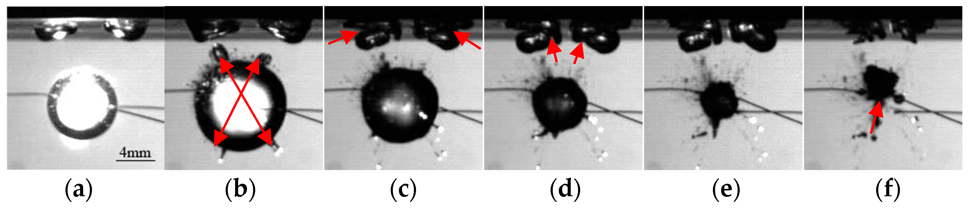
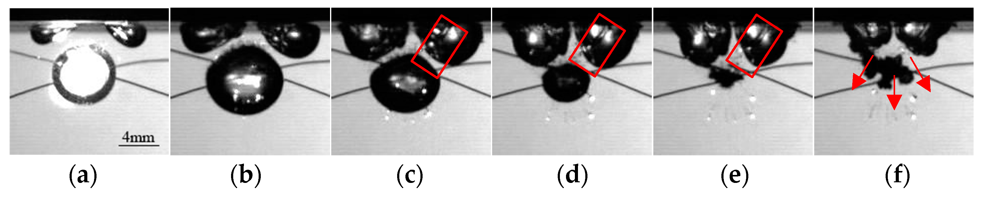
3.2. Layout II: Bubble Motion Characteristics on the Symmetry Axis of Two Air Bubbles

3.2.1. Jet towards the Boundary

Figure 6 shows the coupling pulsation of three bubbles with a dimensionless distance parameter γs = 1.85, initial volumes of attached air bubbles Ve1 = 0.04 mL and Ve2 = 0.04 mL, an inclination angle of α = 20° between the bubble and the two air bubbles, and an air bubble spacing parameter of γL = 0.50. The bubble is generated on the symmetrical axis of the two air bubbles, causing the effects of the air bubbles on the bubble to be symmetrically distributed. In Figure 6a, during bubble expansion, the air bubbles are visibly compressed near the symmetry axis, while the sides farther from the axis maintain a larger shape. In Figure 6b, the bubble reaches its maximum volume Vm = 0.52 mL at 1.26 ms. However, in this frame, four directional bulges are visible along the line connecting the centroids of the two air bubbles and the bubble, likely caused by remnants of the copper wire, but their movement direction also indicates the influence of the two air bubbles. Figure 6c shows the bubble contracting spherically, with the bulges receding and leaving trails, while the air bubbles exhibit a rapid collapse on the outer sides and convergence on the inner sides. At 1.84 ms, the bubble continues to contract, forming a new bulge in the middle of the lower surface, with the air bubbles, showing irregular, symmetrically distributed layering. At 1.94 ms, the bubble contracts to its minimum volume, and during the rebound phase, the bulge on the lower surface splits, leaving a trail, while the air bubbles move closer together and undergo severe surface deformation, as shown in Figure 6f.

3.2.2. Multidirectional Jet

Figure 7 shows the coupling pulsation of three bubbles with a dimensionless distance parameter γs = 1.37, initial volumes of attached air bubbles Ve1 = 0.04 mL and Ve2 = 0.04 mL, an inclination angle of α = 32° between the bubble and the two air bubbles, and an air bubble spacing parameter of γL = 0.54. In this setup, the distance parameter between the bubbles is relatively small, resulting in strong coupling effects among the three bubbles. At 0.78 ms, the bubble reaches its maximum volume, and it is evident that the air bubbles significantly inhibit the bubble in the later stages of expansion. The upper surface of the bubble becomes pointed while the lower surface remains smooth. The asymmetric expansion of the two air bubbles is clearly observable at this time. In Figure 7c, as the bubble enters the contraction phase, its volume decreases while the volume of the air bubbles increase. A distinct internal connecting jet is visible within air bubble 2, persisting until the bubble’s rebound phase, whereas no significant jet is observed within air bubble 1. At 1.36 ms, the bubble collapses to its minimum volume, and the uneven rebound of the bubble is seen to form jet trails in three directions: the downward direction, the left downward direction, and the right downward direction. However, the underlying cause of this phenomenon is still not entirely clear. It is possible that this phenomenon is triggered by a combination of factors, such as the out-of-phase pulsation between the bubble and the air bubbles and the effect of the copper wire on the bubble shape.

3.2.3. Jets Departing from the Boundary

Figure 8 shows the overall response of the coupling structure with a dimensionless distance parameter γs = 3.88, an initial volume of attached air bubbles at Ve1= Ve2 = 0.05 mL, an inclination angle of α = 15° between the bubble and the two air bubbles, and an air bubble spacing parameter of γL = 0.60. Due to the large distance parameter, the bubble’s initial expansion is minimally affected by the air bubbles, and the response of the two air bubbles during the first pulsation cycle of the bubble is relatively small. At 0.58 ms, the bubble expands to its maximum volume and then contracts while the volumes of the air bubbles increase, reaching their maximum volume when the bubble collapses to its minimum volume. As shown in Figure 8d,e, at 1.16 ms, the two air bubbles contract and move closer to each other on their inner sides. The bubble enters its second pulsation cycle, continuing to expand and rebound in the vertical direction away from the boundary, with its lower surface becoming pointed. At 1.26 ms, the bubble contracts to its minimum volume for the second time, and the air bubbles move towards each other, with their outer sides quickly collapsing inward.

3.3. Displacement Pattern Variations in Individual Bubble Measurement Points

In the pulsation response of a bubble with an inclination angle relative to attached air bubbles, the air bubbles not only exhibit their own pulsation response but also undergo lateral migration. When two air bubbles are attached to a boundary, one or both air bubbles inevitably have a certain inclination angle relative to the bubble, regardless of their arrangement, and the interaction between adjacent air bubbles also affects the motion of the bubble. This section analyzes the displacement of key measurement points and changes in air bubble width under different distance parameters, air bubble spacing, and bubble generation positions to illustrate the evolution characteristics of bubble coupling with multiple attached air bubbles. The horizontal displacement of the reference point is defined as positive to the right, and the vertical displacement is defined as positive upward. It should be noted that the core concept involves detecting the bubble’s outer contour by recognizing color differences between the bubble and adjacent pixels in the bubble-shaped image identification process. The identified edges of the bubble typically exhibit a variance of about 1–2 pixels due to the blurriness present in the images.
The spark discharge technique offers the benefits of cost-effectiveness. However, its primary limitations include less precise control over bubble size and the positioning of electrodes, which are submerged in water [10]. This leads to minor deviations in the initial position of the spark-induced bubble relative to the symmetrical axis of the two attached air bubbles. To mitigate the impact of these deviations on experimental outcomes, experiments are chosen where the distance between the bubble’s centroid and the symmetry axis is within a range of 8 pixels (0.82 mm).

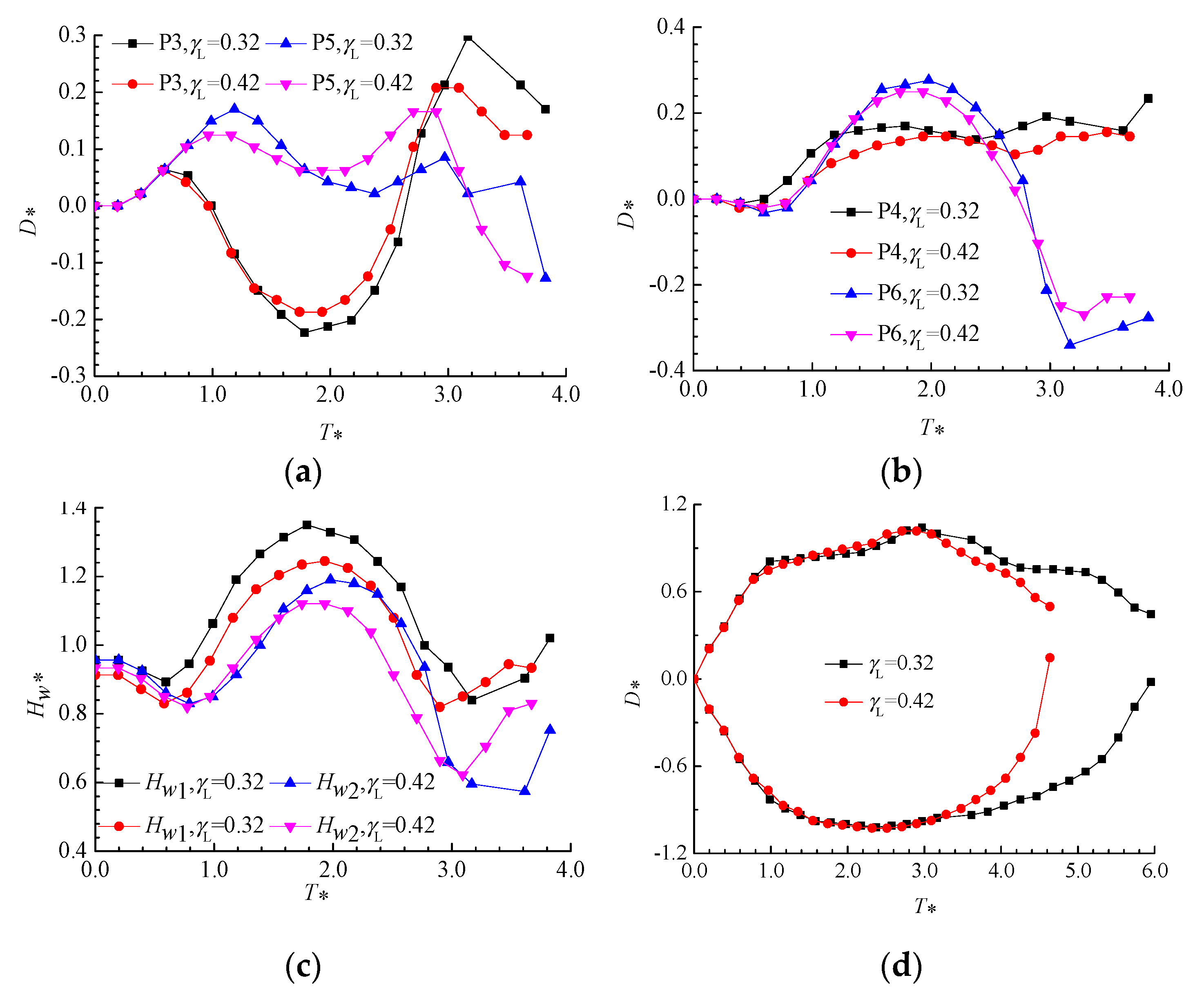
3.3.1. Displacement Variation Patterns of Measurement Points for Layout I

Figure 9 shows the response of various characteristic points under the pulsation effect of the bubble for Layout I, with air bubble spacing at γL = 0.50 and distance parameters γs = 2.99 and γs = 3.61. Other parameters are listed in Table 1. Previous research indicates that when α = 0, the air bubble undergoes a central contraction, taking on a shape akin to a cup cover [30]. When α≠0, the bubble exhibits an inclined cup cover shape [29]. Therefore, to more effectively describe the symmetric and asymmetric cup cover phenomena observed in the experiments, this manuscript presents the time histories of the corresponding measurement points and conducts an analysis. This approach aims to reveal the asymmetric contraction phenomenon of the adhering air bubbles. Figure 9a presents the displacement variations in the left-side point of the attached air bubble under different distance parameters. Under the pressure of the expanding bubble, the air bubble initially undergoes a short-term contraction. During the later stages of bubble expansion and contraction, point P3 consistently moves to the left, away from its initial center position. For the same distance parameter, point P5 reaches its maximum positive displacement later than point P3 due to air bubble 1 being directly below the bubble and, thus, becoming more significantly affected by it, while air bubble 2 is slightly farther from the bubble, resulting in a delayed response time. Compared to point P5, point P3 shows a noticeable minimum value, which decreases as the distance parameter decreases. Figure 9b indicates that, compared to point P6, point P4 reaches its maximum positive displacement earlier, and smaller distance parameters correspond to greater positive displacements for the right-side points of the two cavitation bubbles. It is noteworthy that the displacement amounts of points P3 and P4 around air bubble 1 are not entirely equal, indicating that the pulsation response of the air bubble is influenced not only by the bubble in the vertical direction but also by the nearby air bubble in the horizontal direction. Additionally, points P3 and P6 are free ends mainly affected by internal pressure changes, whereas the influence between the air bubbles on points P4 and P5 cannot be ignored. Consequently, the number of displacement points for P3 and P6 are always greater than those of points P4 and P5, demonstrating that the interaction between the two air bubbles somewhat restricts their movement. Figure 9c shows that the sequence of the width peaks is as follows: air bubble 1 with γs = 2.99 > air bubble 2 with γs = 2.99 > air bubble 1 with γs = 3.61 > air bubble 2 with γs = 3.61. In Figure 9d, it can be seen that due to the large distance parameter, the displacement differences between the top and bottom vertices of the bubble are not significant. Only at the end of the bubble contraction phase is the contraction of the top vertex for γs = 3.61 slower.
Figure 10 shows the response of various characteristic points under the pulsation effect of the bubble for Layout I, with a distance parameter γs = 2.15 and air bubble spacings of γL = 0.32 and γL = 0.42. Other parameters are listed in Table 2. This section mainly studies the impact of air bubble spacing. Figure 10a shows the displacement variations in the left-sided points (P3 and P5) of the two air bubbles. For air bubble 1, the displacement trend in point P3 is the same under different air bubble spacings, and compared to γL= 0.42, both the positive and negative maximum displacements of point P3 are larger when γL = 0.32. Ultimately, the two air bubbles merge at 1.84 ms in the case of γL = 0.32. Compared to γL = 0.42, the positive maximum displacement of point P5 is larger, while the second peak is smaller when γL = 0.32. From Figure 10b, it can be seen that when γL = 0.32, the displacement of point P4 is significantly smaller than that of point P6. Compared to γL = 0.42, the maximum displacement of point P6 is larger, while the minimum displacement is smaller when γL = 0.32, which is the opposite trend in point P3. The movement differences between points P3 and P4 indicate that the smaller the air bubble spacing, the more pronounced the coupling effect between the two air bubbles is. As the air bubbles contract, the internal pressure rises, and the tendency for the air bubbles to contract inward becomes more apparent. Figure 10c shows that air bubble 1, which bears the vertical pressure from the bubble, achieves a greater maximum width during expansion than air bubble 2, and this maximum value decreases with increasing air bubble spacing. Additionally, from Figure 10d, it can be seen that at a distance parameter of γs = 2.15, during the bubble expansion phase, the movements of points P1 and P2 overlap under different air bubble spacings, with significant differences only appearing during the bubble contraction phase.

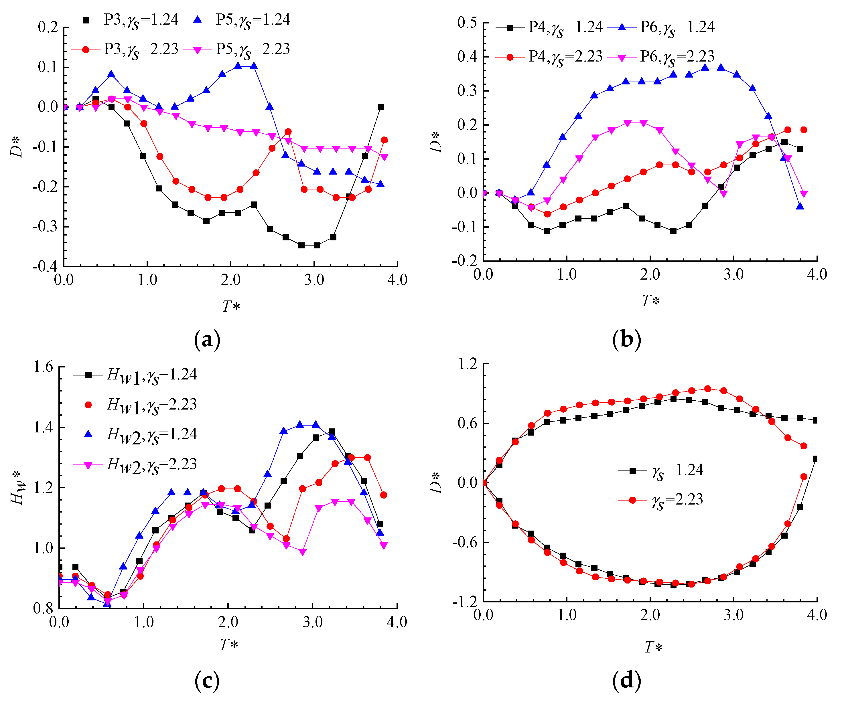
3.3.2. Displacement Variation Patterns of Measurement Points for Layout II

Figure 11 shows the response of various characteristic points under the pulsation effect of the bubble for Layout II with air bubble spacing of γL = 0.44 and distance parameters γs = 1.24 and γs = 2.23. Other parameters are listed in Table 3. Due to the symmetrical arrangement, the displacement trends in the points exhibit good symmetry. The minor discrepancies in the displacement of individual points in the figure may be attributed to the limitations in the precision of the bubble generation site, resulting in the centroid of the bubble not accurately appearing on the axis of symmetry. As seen in Figure 11a, the displacement of point P3 experiences two troughs, with the trough values increasing as the distance parameter γs increases. The variation in point P5 is more pronounced, with γs = 1.24 showing significant fluctuations in displacement, indicating that the left side of air bubble 2 responds noticeably to the bubble’s pulsation. However, with γs = 2.23, the displacement of point P5 is smoother, moving a certain distance forward and then slowly rebounding. In Figure 11b, compared to Figure 11a, the displacement trends and amplitudes of the corresponding symmetric points are exactly opposite, mainly due to the symmetrical arrangement of the bubbles. Figure 11c shows that the width reaches two peaks, with the second peak being larger than the first. When γs = 1.24, the air bubbles undergo secondary pulsation during the bubble contraction. The smaller distance parameter leads to a greater degree of the secondary expansion of the air bubbles, causing the width of the secondary expansion to exceed that of the initial expansion. Figure 11d indicates that the upper surface of the bubble undergoes two fluctuations corresponding to the two pulsations of the air bubbles, and the displacement of the upper vertex of the bubble is significantly influenced by the suppression effect of the nearby air bubbles. The upper and lower vertices are not symmetrically distributed.
Figure 12 shows the displacement changes in key points of the bubbles and the variation in air bubble width for Layout II with the distance parameter γs at approx 1.80 and air bubble spacings of γL = 0.39 and γL = 0.59. Other parameters are listed in Table 4. When the distance parameter remains constant, changing the initial air bubble spacing is equivalent to changing the initial offset angle of the air bubbles, with the effective initial offset angle α increasing as the air bubble spacing increases. Here, γL = 0.39 corresponds to an effective inclination angle of approximately 20°, and γL = 0.59 corresponds to an effective inclination angle of approximately 25°. As shown in Figure 12a, point P3 moves noticeably to the left during air bubble expansion, with an overall trend similar to that of point P3 in Figure 10a. The influence of changes in air bubble spacing is similar to that of changes in the distance parameter. When γL = 0.39, the displacement shows a continuous downward trend, with the displacement being greater than the corresponding displacement of point P5 when γL = 0.59. In Figure 12b, it can be seen that when γL = 0.39, the displacement changes in point P4 before the fusion of the air bubbles are very noticeable. The difference in the displacement peak of point P4 during the expansion phase for γL = 0.39 compared to γL = 0.51 is significantly greater than the corresponding difference for point P5 under the same parameters. This may be due to the offset distance between the bubble centroid and the symmetry axis, leading to asymmetrical displacement distribution. Additionally, the peak displacement of point P6, when γL = 0.59, is smaller than when γL = 0.36, indicating that the smaller the air bubble spacing, the greater the displacement of the outer points of the corresponding air bubbles. Figure 12c shows that the width changes in the two air bubbles are significantly different for γL = 0.39, which may be due to the different initial volumes of the air bubbles. Figure 12d indicates that the variation in air bubble spacing has no significant effect on bubble pulsation, with only some impact on the upper vertex during the contraction phase.

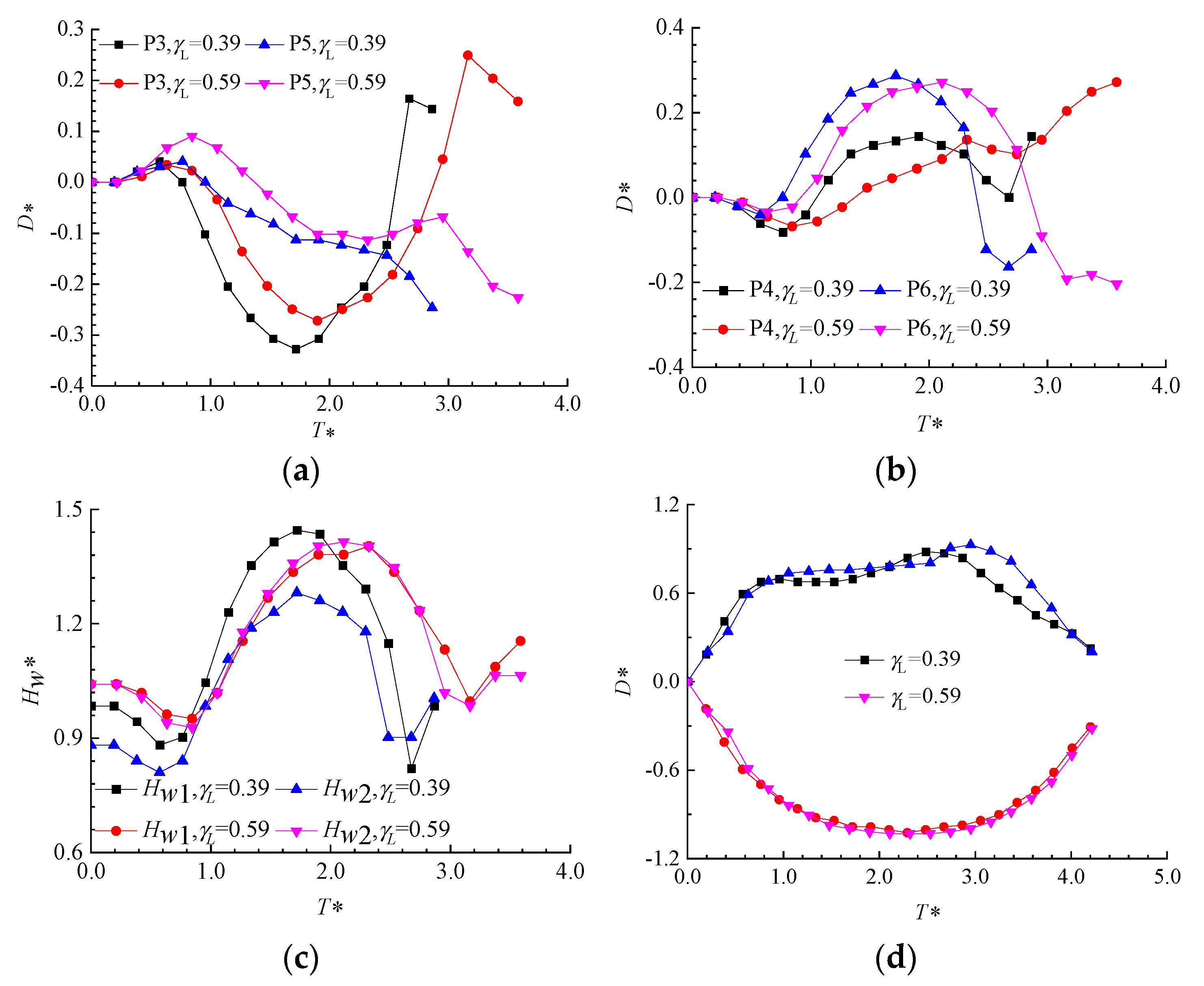
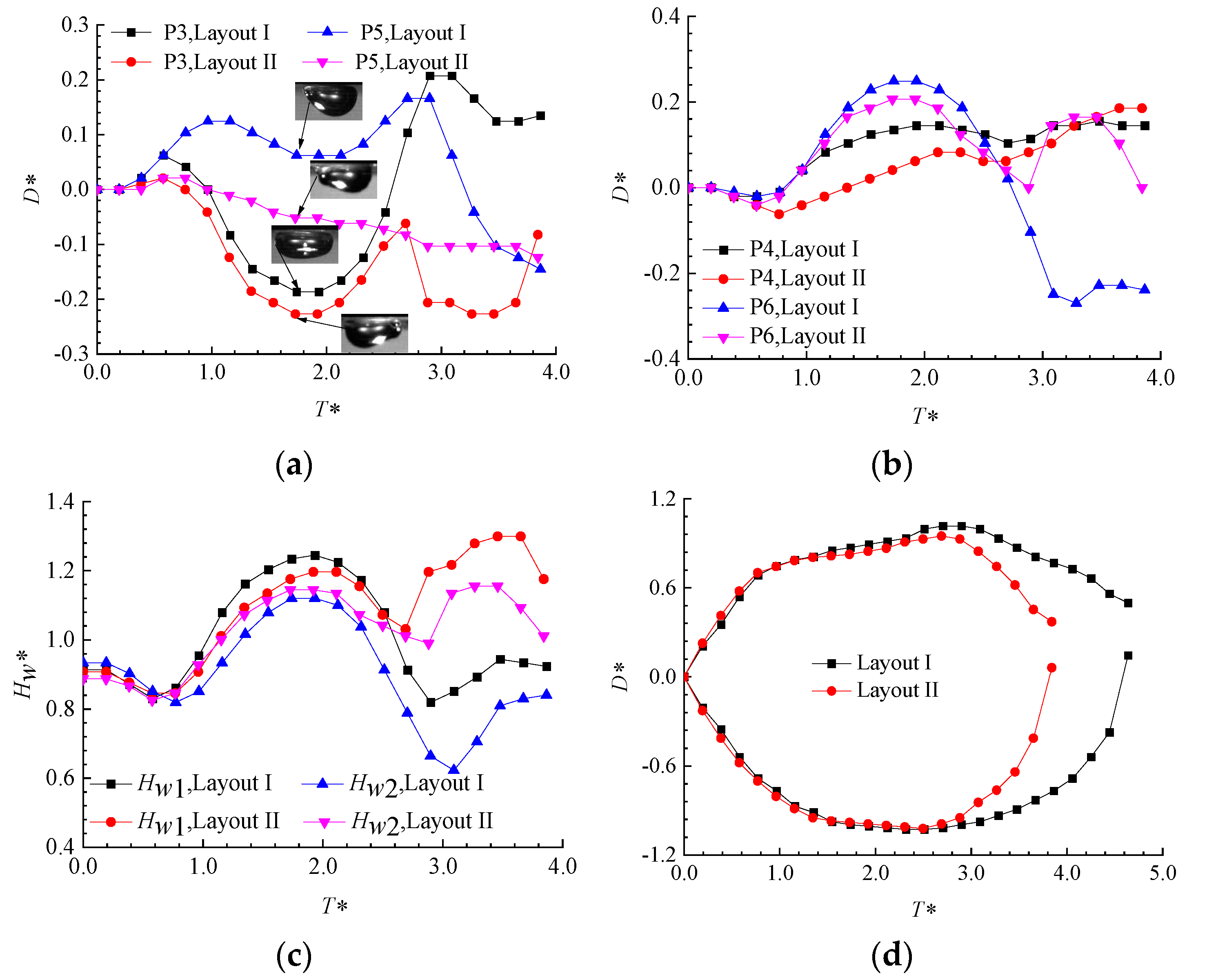
3.3.3. Comparison of Displacement Changes at Various Measurement Points When the Bubble Is Generated at Different Positions

Figure 13 shows the displacement of various measurement points and the width of the air bubbles over time when the initial generation position of the bubble is changed, with a dimensionless distance parameter γs of approx 2.20 and air bubble spacing of γL = 0.42. This study primarily investigates the impact of spatial layout on the coupling pulsation effect of the three bubbles. Other parameters are listed in Table 5. The layouts are Layout I and Layout II, with condition one selected from Figure 10 and condition two from Figure 11. In Figure 13a, it can be seen that under similar parameter conditions, the reverse displacement value of point P3 for air bubble 1 in condition one is greater compared to air bubble 1 in condition two. This is because there is a certain inclination angle between the bubble and the two air bubbles in Layout II. During the secondary contraction of air bubble 1 in both conditions, the displacement of point P3 shows significant differences due to the different bubble positions. In Figure 13b, the displacement of point P4 in both layouts is similar, with point P4 in Layout I showing almost identical maximum displacement values twice. During the first expansion of the air bubble to its maximum volume, the displacements of points P4 and P6 in Layout I were greater than those in Layout II. The displacement trends in point P6 and point P3 in both layouts were similar but opposite in value. Figure 13c shows that, in terms of width changes, the direct effect of the bubble on air bubble 1 in Layout I significantly reduced the internal pressure of the air bubble, resulting in HW1 reaching a higher peak after the initial contraction. Additionally, in Layout II, the maximum width of the secondary expansion of the two air bubbles was greater than the maximum width during the initial pulsation of the air bubbles. Figure 13d shows that, compared to Layout I, the pulsation period of the bubble in Layout II reduced by 17.4%, which may be due to the uneven local pressure exerted by the air bubbles on the bubble.

4. Conclusions

This paper experimentally studies the motion characteristics of bubbles near a rigid boundary with two attached air bubbles. First, the complex jet phenomena and coupled pulsation effects of air bubbles under different spatial layouts (Layout I and Layout II) were analyzed. Next, the impacts of the dimensionless distance parameter γs from the bubble to the boundary, the spacing γL between the two air bubbles, and the spatial layout were examined. Through the examination of special air bubbles and bubble pulsation morphologies along with jet characteristics, the strong nonlinear coupling effect was revealed to be exerted by multiple adhering air bubbles on the oscillating bubble. These findings may offer valuable insights into the preservation of structures that are vulnerable to the effects of underwater explosion-induced bubbles and may hold significant implications for the anti-erosion design considerations in hydraulic engineering applications. The following conclusions were drawn:
  • For spatial Layout I, the experiments observed that a bubble directly below a single air bubble produces a jet directed towards the distant air bubble. The oscillating bubble undergoes a tearing phenomenon in the direction towards the lower left, which is caused by the vectorial summation of the repulsive forces exerted by the two adhering air bubbles on the oscillating bubble. Compared to Layout II, the bubble only exhibits off-axis migration and jet direction in Layout I. There is an inclination angle between the other air bubbles and the bubble.
  • For spatial Layout I, when the air bubble spacing γL is fixed, the displacement of the air bubble directly above the bubble is proportional to the distance parameter γs, and this also causes varying degrees of lateral displacement in the two air bubbles, with the lateral displacement of air bubble 2 being more significant.
  • For spatial Layout I, when the distance parameter γs is constant, the positive pressure exerted by the bubble on air bubble 1 directly above is proportional to the air bubble spacing γL, and the displacement of the outer endpoint of air bubble 2 increases with the increase in γL.
  • For spatial layout II, when the air bubble spacing γL is fixed, the displacement of the middle of the air bubbles on both sides increases as the distance parameter decreases. The closer the bubble is to the air bubbles, the more significant the pressure on the air bubbles and the greater the displacement variation. At the same time, the two air bubbles undergo lateral displacements in opposite directions, with the displacement magnitudes changing symmetrically.
  • For spatial Layout II, when the distance parameter γs is fixed, the displacement of the middle of the air bubbles increases as the spacing parameter decreases. Additionally, the displacement variation in the inner points for the middle of the air bubbles is smaller than that for the outer points.

Author Contributions

Conceptualization, K.L.; Methodology, M.J. and J.W.; Data curation, X.Z. and S.W.; Writing – original draft, M.J.; Writing – review & editing, K.L. and J.W. All authors have read and agreed to the published version of the manuscript.

Funding

this work was funded by the National Natural Science Foundation of China (Grant Nos. 52171311; 52271279), the Natural Science Foundation of Jiangsu Province (Grant No. BK20220652).

Institutional Review Board Statement

Not applicable.

Informed Consent Statement

Not applicable.

Data Availability Statement

Data are contained within the article.

Conflicts of Interest

The authors declare no conflict of interest.

References

  1. Song, W.D. Laser-induced cavitation bubbles for cleaning of solid surfaces. J. Appl. Phys. 2004, 95, 2952. [Google Scholar] [CrossRef]
  2. Makuta, T.; Takemura, F.; Hihara, E.; Matsumoto, Y.; Shoji, M. Generation of micro gas bubbles of uniform diameter in an ultrasonic field. J. Fluid Mech. 2006, 548, 113. [Google Scholar] [CrossRef]
  3. Li, Y.-B.; Wu, X.-Y.; Ma, Y.; Wang, J.-G. A method based on potential theory for calculating air cavity formation of an air cavity resistance reduction ship. J. Mar. Sci. Appl. 2008, 7, 98–101. [Google Scholar] [CrossRef]
  4. Blake, J.R.; Gibson, D. Cavitation bubbles near boundaries. Annu. Rev. Fluid Mech. 1987, 19, 99–123. [Google Scholar] [CrossRef]
  5. Zong, Z.; Hong, Z.C.; Zhang, H.; Sahoo, P.K. An investigation of load change of propeller in a four-propulsion vessel using CFD. J. Mar. Sci. Technol. 2018, 23, 122–131. [Google Scholar] [CrossRef]
  6. Rungsiyaphornrat, S.; Klaseboer, E.; Khoo, B.; Yeo, K. The merging of two gaseous bubbles with an application to underwater explosions. Comput. Fluids 2003, 32, 1049–1074. [Google Scholar] [CrossRef]
  7. Cui, P.; Wang, Q.X.; Wang, S.P.; Zhang, A.M. Experimental study on interaction and coalescence of synchronized multiple bubbles. Phys. Fluids 2016, 28, 012103. [Google Scholar] [CrossRef]
  8. Liu, N.N.; Cui, P.; Ren, S.F.; Zhang, A.M. Study on the interactions between two identical oscillation bubbles and a free surface in a tank. Phys. Fluids 2017, 29, 052104. [Google Scholar] [CrossRef]
  9. Robinson, P.B.; Blake, J.R.; Kodama, T.; Shima, A.; Tomita, Y. Interaction of cavitation bubbles with a free surface. J. Appl. Phys. 2001, 89, 8225–8237. [Google Scholar] [CrossRef]
  10. Fong, S.W.; Adhikari, D.; Klaseboer, E.; Khoo, B.C. Interactions of multiple spark-generated bubbles with phase differences. Exp. Fluids 2009, 46, 705–724. [Google Scholar] [CrossRef]
  11. Lauterborn, W.; Hentschel, W. Cavitation bubble dynamics studied by high speed photography and holography: Part one. Ultrasonics 1986, 24, 59–65. [Google Scholar] [CrossRef]
  12. Timm, E.F.; Hammit, F.G. Bubble collapse adjacent to a rigid wall, a flexible wall, and a second bubble. In Proceedings of the ASME Cavitation Forum, Pittsburgh, Pa, USA, 10-12 May 1971. [Google Scholar]
  13. Zhang, S.; Wang, S.P.; Liu, Y.L.; Zhang, A.M.; Cui, P. Interaction of clustered air gun bubbles in marine prospecting. Ocean Eng. 2019, 191, 106523. [Google Scholar] [CrossRef]
  14. Li, T.; Zhang, A.M.; Wang, S.P.; Chen, G.Q.; Li, S. Nonlinear interaction and coalescence features of oscillating bubble pairs: Experimental and numerical study. Phys. Fluids 2019, 31, 092108. [Google Scholar] [CrossRef]
  15. Naing, N.M.T.; Park, J.; Hyun, S.-H.; Jung, R.-T. Impact loads generated by tandem cavitation bubble on solid wall. J. Hydrodyn. 2022, 34, 467–482. [Google Scholar] [CrossRef]
  16. Luo, J.; Niu, Z. Jet and shock wave from collapse of two cavitation bubbles. Sci. Rep. 2019, 9, 1352. [Google Scholar] [CrossRef]
  17. Luo, J.; Xu, W.L.; Khoo, B.C. Stratification effect of air bubble on the shock wave from the collapse of cavitation bubble. J. Fluid Mech. 2021, 919, A16. [Google Scholar] [CrossRef]
  18. Luo, J.; Xu, W.L.; Li, R. Collapse of cavitation bubbles near air bubbles. J. Hydrodyn. 2020, 32, 929–941. [Google Scholar] [CrossRef]
  19. Lv, K.; Zou, J.J.; Chen, Y.; Yan, S.; Li, S.; Zhang A, M. Study on the coupling of heterogeneous double bubbles and jet enhancement effect near rigid wall. Chin. J. Theor. Appl. Mech. 2023, 55, 1605–1617. (In Chinese) [Google Scholar]
  20. Zhang, A.M.; Li, S.M.; Cui, P.; Li, S.; Liu, Y.L. A unified theory for bubble dynamics. Phys. Fluids 2023, 35, 033323. [Google Scholar] [CrossRef]
  21. Wei, Z.J.; Zhang, C.C.; Shen, C.; Wang, L.; Xin, Z.T. Manipulation of bubble collapse patterns near the wall of an adherent gas layer. Ultrason. Sonochemistry 2023, 101, 106722. [Google Scholar] [CrossRef]
  22. Chen, R.; Liang, W.; Zheng, J.; Li, X.Y.; Lin, Y.L. Experimental study on the interaction of three linearly arranged spark bubbles with controlled phase differences. Phys. Fluids 2022, 34, 037105. [Google Scholar] [CrossRef]
  23. Sun, Y.R.; Zhong, Q.; Yao, Z.F.; Zi, D.; Xiao, R.F.; Wang, F.J. Deflection of cavitation bubble near the rigid wall with a gas-containing hole. J. Hydrodyn. 2023, 35, 330–337. [Google Scholar] [CrossRef]
  24. Brujan, E.A.; Zhang, A.M.; Liu, Y.L.; Ogasawara, T.; Takahira, H. Jetting and migration of a laser-induced cavitation bubble in a rectangular channel. J. Fluid Mech. 2022, 948, A6. [Google Scholar] [CrossRef]
  25. Ren, Z.B.; Li, B.; Xu, P.; Wakata, Y.; Liu, J.; Sun, C.; Zuo, Z.G.; Liu, S.H. Cavitation bubble dynamics in a funnel-shaped tube. Phys. Fluids 2022, 34, 093313. [Google Scholar] [CrossRef]
  26. Zhang, Z.F.; Li, H.L.; Zhang, J.Y.; Zhang, G.Y.; Zong, Z. Bubble motion and jet load near elastic-plastic structure under deep-water explosion. Ocean. Eng. 2024, 294, 116750. [Google Scholar] [CrossRef]
  27. Tan, Z.K.; Zhang, M.D.; Huang, G.H.; Huang, B. Collapsing behavior of a spark-induced cavitation bubble near the air bubble attached to the tube nozzle. Ocean. Eng. 2022, 253, 111183. [Google Scholar] [CrossRef]
  28. Wu, J.; Su, K.; Wang, Y.; Gou, W. Effect of air bubble size on cavitation erosion reduction. Sci. China Technol. Sci. 2017, 60, 523–528. [Google Scholar] [CrossRef]
  29. Wang, J.X.; Wu, S.Z.; Liu, K.; Jiang, M.Z.; Wang, Z.L. Experimental Study on Effect of Inclination Angle on Bubble Collapse near Attached Air Bubble. China Ocean Eng. 2023, 37, 753–767. [Google Scholar] [CrossRef]
  30. Wang, J.X.; Liu, K.; Yuan, S.J.; Jiang, M.Z.; Wang, Z.L. Dynamics of the passive pulsation of a surface-attached air bubble subjected to a nearby oscillating spark-generated bubble. Phys. Fluids 2020, 32, 067101. [Google Scholar] [CrossRef]
  31. Cui, J.; Chen, Z.P.; Wang, Q.; Zhou, T.R.; Corbett, C. Experimental studies of bubble dynamics inside a corner. Ultrason. Sonochemistry 2020, 64, 104951. [Google Scholar] [CrossRef]
  32. Goh BH, T.; Ohl, S.W.; Klaseboer, E.; Khoo, B.C. Jet orientation of a collapsing bubble near a solid wall with an attached air bubble. Phys. Fluids 2014, 26, 221–240. [Google Scholar] [CrossRef]
  33. Li, Z.; Sun, L.; Zong, Z.; Dong, J. Some dynamical characteristics of a non-spherical bubble in proximity to a free surface. Acta Mech. 2012, 223, 2331–2355. [Google Scholar] [CrossRef]
  34. Li, S.; Zhang, A.M.; Han, R.; Cui, P. Experimental and numerical study of two underwater explosion bubbles: Coalescence, fragmentation and shock wave emission. Ocean Eng. 2019, 190, 106414. [Google Scholar] [CrossRef]
Figure 1. Schematic of experimental setup.
Jmse 12 01631 g001
Figure 3. The reverse jet flows along the inclined direction. (a) t = 0.68 ms; (b) t = 1.26 ms; (c) t = 1.65 ms; (d) t =1.84 ms; (e) t = 2.13 ms; (f) t = 2.23 ms.
Jmse 12 01631 g003
Figure 4. Middle splitting along the inclined direction. (a) t = 0.68 ms; (b) t = 1.26 ms; (c) t = 1.65 ms; (d) t =1.84 ms; (e) t = 2.13 ms; and (f) t = 2.23 ms.
Jmse 12 01631 g004
Figure 5. Jet toward the plate. (a) t = 0.68 ms; (b) t = 1.26 ms; (c) t = 1.65 ms; (d) t =1.84 ms; (e) t = 1.94 ms; and (f) t = 2.04 ms.
Jmse 12 01631 g005
Figure 6. Jet toward the plate. (a) t = 0.49 ms; (b) t = 1.26 ms; (c) t = 1.65 ms; (d) t =1.84 ms; (e) t = 1.94 ms; and (f) t = 2.13 ms.
Jmse 12 01631 g006
Figure 7. Bubble splitting in multiple directions. (a) t = 0.49 ms; (b) t = 0.78 ms; (c) t = 1.07 ms; (d) t =1.26 ms; (e) t = 1.36 ms; and (f) t = 1.46 ms.
Jmse 12 01631 g007
Figure 8. Jet away from plate. (a) t = 0.39 ms; (b) t = 0.58 ms; (c) t = 0.87 ms; (d) t =0.97 ms; (e) t = 1.16 ms; and (f) t = 1.26 ms.
Jmse 12 01631 g008
Figure 9. The displacement change in reference points for Layout I with γL = 0.50. (a) The point displacement on the left side of the two air bubbles changes; (b) the displacement on the right side of the two air bubbles changes; (c) the width of the two cavities changes; and (d) the displacement of the upper and lower vertex of the bubble changes.
Jmse 12 01631 g009
Figure 10. The displacement change in the reference point for Layout I with γs = 2.15. (a) The point displacement on the left side of the two air bubbles changes; (b) the displacement on the right side of the two air bubbles changes; (c) the width of the two cavities changes; and (d) the displacement of the upper and lower vertex of the bubble changes.
Jmse 12 01631 g010
Figure 11. The displacement of reference points for Layout II with γL = 0.44. (a) The point displacement on the left side of the two air bubbles changes; (b) the displacement on the right side of the two air bubbles changes; (c) the width of the two cavities changes; and (d) the displacement of the upper and lower vertex of the bubble changes.
Jmse 12 01631 g011
Figure 12. The displacement of the reference point for Layout II with γs ≈ 1.80. (a) The point displacement on the left side of the two air bubbles changes; (b) the displacement on the right side of the two air bubbles changes; (c) the width of the two cavities changes; and (d) the displacement of the upper and lower vertex of the bubble changes.
Jmse 12 01631 g012
Figure 13. The displacement of each measuring point varies with time when the bubble is in different positions. (a) The point displacement on the left side of the two air bubbles changes; (b) the displacement on the right side of the two air bubbles changes; (c) the width of the two cavities changes; and (d) the displacement of the upper and lower vertex of the bubble changes.
Jmse 12 01631 g013
Table 1. Some parameters for the cases presented in Figure 9.
γsRe1 (mm)Re2 (mm)Rm (mm)V
2.992.772.773.674.66
3.612.712.693.484.30
Table 2. Some parameters for the cases presented in Figure 10.
γLRe1 (mm)Re2 (mm)Rm (mm)V
0.322.742.684.9011.82
0.422.712.725.0112.64
Table 3. Some parameters for the cases are presented in Figure 11.
γsRe1 (mm)Re2 (mm)Rm (mm)V
1.242.742.745.1012.98
2.232.722.605.0513.70
Table 4. Some parameters for the cases presented in Figure 12.
γLRe1 (mm)Re2 (mm)Rm (mm)V
0.392.802.635.0712.93
0.592.642.684.6010.32
Table 5. Some parameters for the cases presented in Figure 13.
LayoutγsγLRe1 (mm)Re2 (mm)Rm (mm)V
I2.150.422.712.725.0112.64
II2.230.422.722.605.0513.70
Disclaimer/Publisher’s Note: The statements, opinions and data contained in all publications are solely those of the individual author(s) and contributor(s) and not of MDPI and/or the editor(s). MDPI and/or the editor(s) disclaim responsibility for any injury to people or property resulting from any ideas, methods, instructions or products referred to in the content.

