Article

Effects of Tool Coatings on Energy Consumption in Micro-Extrusion of Aluminum Alloy 6063

by
Sedthawatt Sucharitpwatskul
1,
Numpon Mahayotsanun
1,*,
Sujin Bureerat
1 and
Kuniaki Dohda
2
1
Department of Mechanical Engineering, Faculty of Engineering, Khon Kaen University, 123 Moo 16 Mittraphap Rd., Nai-Muang, Muang 40002, Thailand
2
Department of Mechanical Engineering, Northwestern University, 2145 Sheridan Road, Evanston, IL 60208, USA
*
Author to whom correspondence should be addressed.
Coatings 2020, 10(4), 381; https://doi.org/10.3390/coatings10040381
Submission received: 31 March 2020 / Revised: 9 April 2020 / Accepted: 11 April 2020 / Published: 13 April 2020
(This article belongs to the Section Tribology)

Abstract

:
The tool wear rate and energy consumption were typically unknown in micro-extrusion, which made it difficult to optimize the tool design for both the final part quality and production cost. This study investigated the effects of tool coatings on energy consumption in the micro-extrusion of aluminum alloy 6063. Three main factors were considered in this study: (1) tool coating types, (2) bearing length, and (3) extrusion ratio. The micro-extrusion finite element simulation model was developed and validated with the micro-extrusion experiment. The results showed that increasing bearing lengths led to the increase in tool wear rate and energy consumption for all the coating types. The decreasing coefficient of friction values of the tool-billet interface led to a decrease in energy consumption. High hardness values of the tool surface and low bearing lengths helped increase tool life. Low values of coefficient of friction and bearing lengths helped decrease energy consumption.

1. Introduction

Global demands in aluminum consumption have been rising, particularly in the areas that need lightweight [1]. New products, solutions, and processes must be developed in order to meet such high demands. Aluminum extrusion is one of the vital metal forming processes that provide net-shape and mass-production benefits [2]. The recent trend in miniaturization has shown that metallic micro parts (mechanical micro connector pins, miniature contact springs, and electronic parts with micro features) are growing in automobiles and electronics [3]. Micro-biomedical parts ranging from rod, wire, ribbon, and tube drawing, to sheet and foil manufacture, and highly precise screw machining are also commercially available [4]. One of the possible technologies to produce these metallic parts is micro forming [5]. The micro-extrusion process can be utilized to produce high precision miniaturized parts to add higher value to aluminum extrusion products [5,6,7]. Besides, increased strengths of micro-parts can also be achieved by using micro-extrusion [8,9,10,11,12,13,14].
Tribology heavily plays an essential role in micro-extrusion due to the increase in surface areas in comparison to the part dimensions [15,16]. Typical friction tests used in macro-extrusion might no longer be practical in the micro-scale [17,18]. To successfully characterize tribological behaviors in micro-extrusion, friction tests that can simulate the real forming conditions should be considered [19,20,21]. Fundamentally, an oxide layer formed on steel surface caused high friction, and the coefficient of friction was sensitive to the surface roughness during forming without lubrication [22]. Tool wear is apparent in extrusion due to the plastic deformation due to sliding [23,24]. Thus, different types of tool coatings have been used to solve the wear problem [25,26]. For instance, in aluminum extrusion, AlCrN could be coated on the extrusion die (H13 material) [27]. Titanium coatings could also be applied to the steel surfaces [28].
Recently, Diamond-Like Carbon (DLC) has been applied in metal forming to reduce severe tool wear [29,30,31,32]. There have also been environmentally friendly multi-functional additives that can be applied to steel coating under severe mechanical, thermal, and chemical conditions [33]. Our previous work on applying different coatings to the micro forward-backward extrusion tools showed that DLC provided excellent tribological characteristics [34]. Based on our previous work on the Forward-Backward, Vertical, Slow-Speed Micro-Extrusion, we investigated the effects of tool geometry (die angle) and coating types (CrN, TiN, and DLC-PVD). However, there were the following factors that must be investigated further: (1) DLC-CVD, (2) high-speed extrusion, and (3) bearing length. In addition, the aspects of tool wear and energy consumption must be considered to optimize the production cost. Energy consumption is one of the crucial factors in micro-extrusion since it is directly related to cost and environmental impact [35]. Although extrusion of micro-scale products seems to consume minimal energy, producing these tiny parts in mass-production could be a great concern. Since experimental investigation on effects of tribology in micro-extrusion is difficult to setup and critical parameters are not easily measured, finite element simulation has been commonly used to analyze the forming and tribological behaviors in micro-extrusion [36].
The objective of this paper was to investigate the effects of tool coatings used in micro-extrusion to energy consumption. Various tool coatings were considered in this study. Finite element simulation was carried out to predict the energy consumption. The novelty of this was the investigation of wear rate and energy consumption of the considered tool coatings in an extrusion cycle. The obtained results and the information regarding the actual coatings development costs would provide the micro-manufacturing community the tool design guidelines in micro-extrusion.

2. Materials and Methods

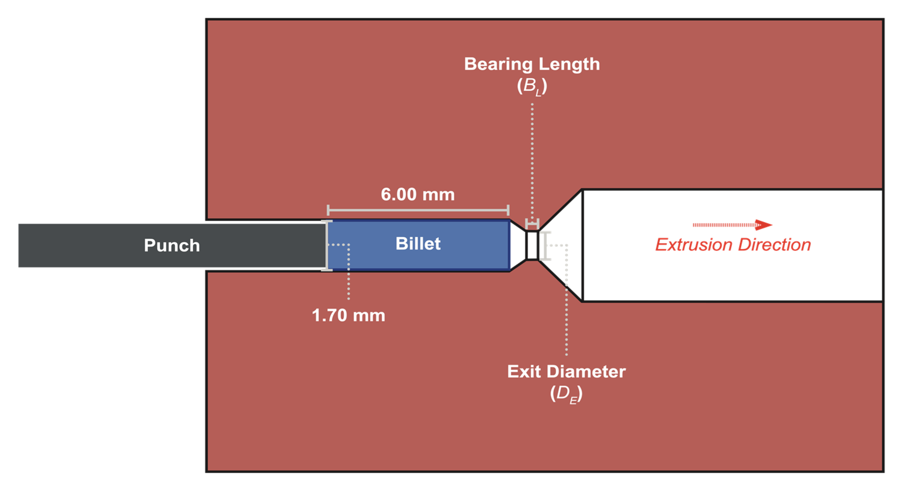
2.1. Micro-Extrusion Experiment

The micro-extrusion machine used in this study is shown in Figure 1, which consists of actuator and extrusion assembly. The punch and dies are located in the extrusion assembly, as shown. The actuator could provide up to 19 kN force, 230 mm/s speed, and 30 mm stroke length. During the extrusion operation, a prepared billet was placed in the cavity of the dies. The punch was then moved to push the billet into the die cavity, extruding the billet into a smaller part. The experiments were carried out at room temperature with a ram speed of 100 mm/s and a forming stroke of 3.0 mm.

2.2. Materials

The billet material under investigation was 6063 aluminum alloy. The specimen billets were fabricated to have 1.7 mm in diameter and 6 mm in length by hot extrusion and machining. The non-annealed billets had a microstructure having approximately 64 µm grain size and a hardness value of 31 HV. The grain size of the billet material was measured by using the standard ASTM E112 [37]. The purpose of measuring the grain size was to quantitatively measure the average number of grains across the billet diameter. Since the investigated grain size was 64 µm, the average number of grains was approximately 27, which should provide homogeneous material property. As a result, the selected material model for the finite element was the power-law. The material model of the billet material was obtained, as shown in Equation (1).
σ = (168.4 MPa) · ε0.3
where σ is the flow stress, and ε is the true strain. The punch and die materials were SKD11. The lubricant having 2.606 mm2/s kinematic viscosity was applied between the die cavity and prepared billet before extrusion.

2.3. Considered Factors

The main factors investigated in this study were: (1) tool coating types, (2) bearing length (BL), and (3) extrusion ratio (ER), as illustrated in Figure 2 and Table 1, Table 2 and Table 3.
The tool coatings were developed and manufactured by Onward Giken Co. (Ishikawa, Japan). Chromium Nitride (CrN), Titanium Nitride (TiN), Diamond-Like Carbon (DLC) were commonly applied to tool coatings in severe forming applications. Note that DLC-CVD was the DLC coating produced by using Chemical Vapor Deposition (CVD). DLC-PVD was the DLC coating produced by using Physical Vapor Deposition (PVD). The coating properties were specific for this study only. The coating hardness values were measured by Vickers Hardness Testing. The coating thickness measurement was carried out by using the microscope. Note that the difference in coating thickness values was due to the available coating options provided by Onward Giken Corporation, Japan. The coefficient of friction values was obtained from the ball-on-disc test.
The extrusion ratio (ER) could be calculated from Equation (2).
ER = (π/4) · (DC2/DE2)
where DC is the container diameter, and DE is the exit diameter. Note that the container diameter (DC) used in this study was constant (1.70 mm), and the exit diameters (DE) were varied to obtain different ER values.

2.4. Finite Element Simulation

The Lagrangian finite element code MSC.Marc 2017 was used to investigate the considered factors, as illustrated in Figure 3. The following assumptions were made: (1) 2D axisymmetric conditions, (2) no heat transfer to the tools, and (3) using the power-law material model. An axisymmetric model was set up to simulate the extrusion process. The 4-node fully integration element was used, resulting in 2040 elements. The tools (punch, container, die bearing, and die relief) were designated as rigid bodies. The initial diameter of the cylinder billet was 1.7 mm, and its length was 6 mm. In order to accurately describe the interface condition between billet and tooling, three friction models were evaluated.

2.4.1. Coulomb Friction Model

This is an approximate model to calculate the friction force, resisting the relative lateral motion of two solid surfaces in contact. The two regimes of friction are static friction between non-moving surfaces. The governing equation is shown in Equation (3).
f = μsN
where f is friction force, μs is the static friction coefficient, and N is the normal load. The Coulomb friction force (f) may take any value from zero up to μsN, and the direction of the frictional force against a surface is opposite to the motion that the surface would experience in the absence of friction.

2.4.2. Shear Friction Model

Shear friction model, which relates the friction stress to the shear strength of the deformed material. This model uses shear flow stress to replace friction stress when friction stress is greater than the shear strength of the deformed material. When the friction stress is lower than the shear strength of the deformed material, the friction stress follows the Coulomb friction law. The shear friction model can be written, as shown in Equation (4).
f = k when ≥ μsN
where k is the shear friction force.

2.4.3. Combined Friction Model

The Coulomb friction law is typically used in combination with limiting stress when the friction stress is lower than the shear strength of the deformed material. When the calculated friction stress is greater than the shear strength of the deformed material, shear flow stress is used to replace the friction stress. This model was also applied in the micro-forming process carried out by Ghassemali et al. [38]. The governing equation of this model is shown in Equation (5).
f = μsN, when μsN < k; f = k when μsNk
The coefficient of friction values used in this study was varied based on the considered tool coatings.
The main purpose of this study was to determine precisely how each considered coating could reduce wear and consume energy in one extrusion cycle. The finite element model was validated with three experiments (one extrusion cycle each). In the validation condition, the billet was extruded from 1.70 mm to 1.09 mm with 100 mm/s speed and 2 mm stroke. The coating used in the validation condition was DLC-PVD. The same trend could be observed on the other considered coatings. The simulation results were compared with those of the experiment, as illustrated in Figure 3. The extrusion forces of both simulation and experiment were plotted against the extrusion stroke. The Coulomb friction model provided the highest extrusion force. Both shear friction and combined friction had similar values of extrusion forces, lower than those of the Coulomb friction model. Based on the observation of forming behaviors of micro-extrusion experiments, the Coulomb friction model tended to overestimate the friction stress, particularly under high contact pressures. When the friction stress was greater than the shear strength of the deformed material, shear flow stress should be used to replace the friction stress. Nevertheless, when the friction stress was lower than the shear strength of the deformed material, the friction stress should follow the Coulomb friction model. As a result, the combined friction model was selected in order to represent the tool-billet interface in this study.
The wear rate and energy consumption of one extrusion cycle were critical for our study due to the following reasons:
(1)
The wear rate per cycle would be used to predict the number of cycles prior to tool wear (coating thickness depletion). Thus, the final part geometry could be precisely controlled, and the tool could be adequately maintained, lowering the production cost.
(2)
The energy consumption per extrusion cycle would be used to predict the energy cost by using each considered tool coating. Each extrusion energy cycle would be multiplied by the predicted number of cycles from (1) to obtain the total energy consumption.
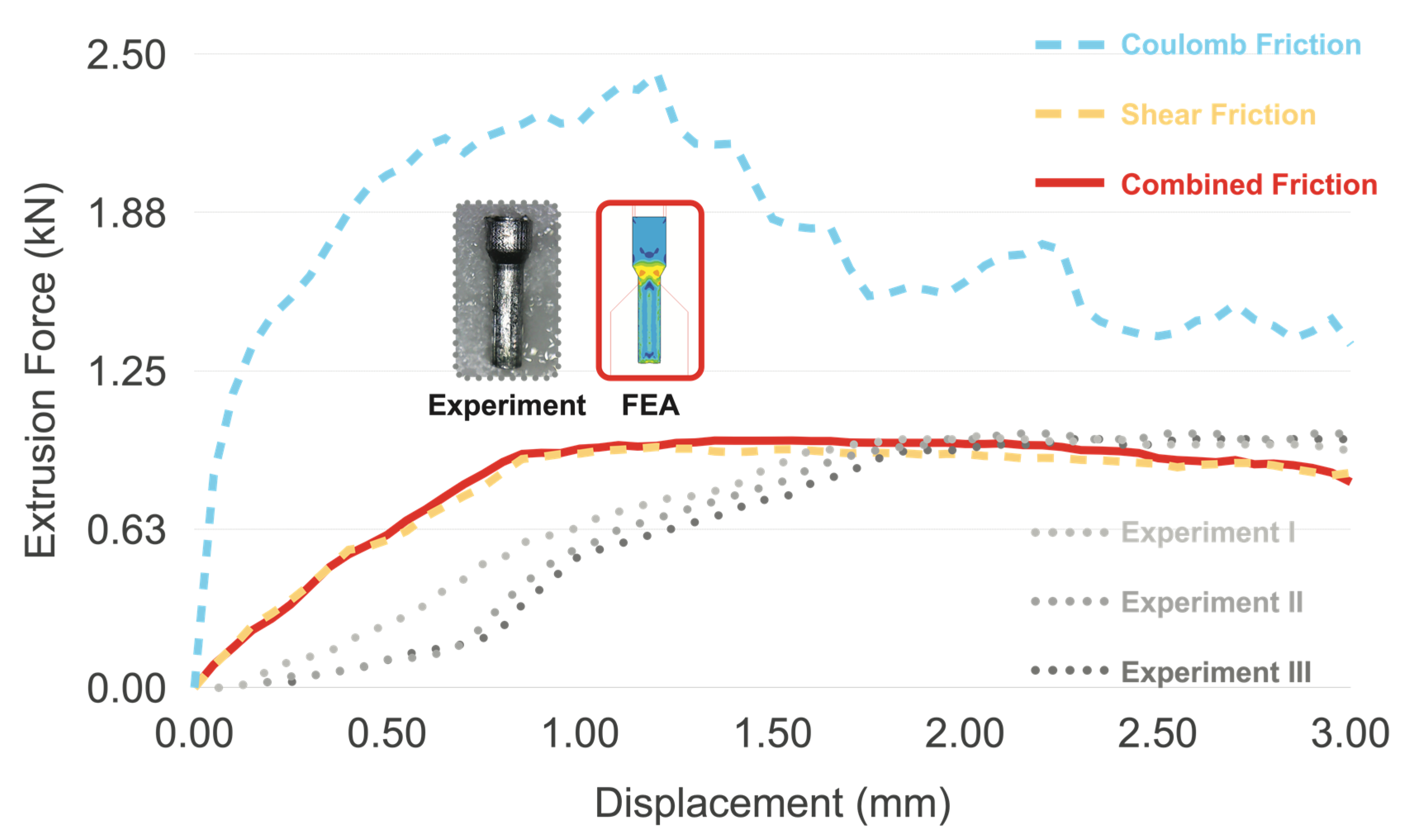
Both of the calculated values from (1), (2), and the actual coatings development costs would provide the tool design guidelines for the micro-extrusion engineers.
After the finite element simulation model was validated, the considered factors shown in Table 1, Table 2 and Table 3 were used as the input parameters to the finite element simulation. The tool wear rate was also investigated in this study by using Archard’s equation, as shown in Equation (6).
W = K × F × Gt/H
where W is tool wear, K is the wear coefficient (K = 1 × 10⁻¹² in this study), F is the normal load, Gt is the sliding distance, and H is the hardness of the worn material (Table 1). In order to evaluate the tool wear rate (Wr), the above equation could also be written in Equation (7).
Wr = K × σ × V/H
where σ is the normal stress, and V is the relative velocity, which is 100 mm/s in this study.
In order to evaluate the effects of tool coatings on energy consumption (E), the extrusion forces (F) obtained from each testing condition were multiplied by the extrusion stroke (S), as shown in Equation (8).
E = F × S
Since only one extrusion cycle was compared for all the testing conditions, tool wear rate and extrusion energy would be considered only for one cycle as well.

3. Results

The comparison of tool wear rates among the considered tool coatings is illustrated in Figure 4. Note that these were the comparison results from the simulations. In addition, the left figure (ER = 2.43) was the enlarged section of tool wear rate of the right figure (ER = 9.55). According to the figure, the tool wear rate of all the coatings increased with bearing length and extrusion ratio. This was due to the fact that higher bearing length increased the sliding lengths between the billet and the tools, causing the tool wear rate to increase. High extrusion ratio also implied that the forces required to plastically deform the billet into the die increased, causing higher stresses to the tools; thus, tool wear rate increased. At both extrusion ratios, increasing bearing length from 0.5 mm to 3.0 mm would increase the tool wear rate of approximately 40%. This phenomenon should be noted because extrusion engineers tend to increase bearing lengths in order to balance the material flow without realizing that a slight increase in bearing lengths could shorten tool life dramatically. Since the tool wear rate was inversely proportional to the tool hardness, the highest to lowest tool wear rate values range from CrN, TiN, DLC-CVD, and DLC-PVD, respectively. If the tool wear rates between DLC-CVD and DLC-PVD were compared, DLC-PVD provided lower tool wear rates than DLC-CVD did. This was mainly due to the fact that DLC-PVD had higher coating hardness value. Since the tool-billet interfaces of both DLC-CVD and DLC-PVD had the same coefficient of friction, the higher hardness value of DLC-PVD played an important role in lowering the tool wear rats. As a result, coatings that provided high hardness values would generally provide longer tool life. Nevertheless, the hardness values used in this study were mainly the hardness values of the tool surface (coated thickness shown in Table 1). One should be concerned that the bulk hardness values of the tool should not be too high, which would easily cause tool breakage.
The comparison of energy consumptions among the considered tool coatings is displayed in Figure 5. Note that these were the comparison results from the simulations. In addition, the left figure (ER = 2.43) was the enlarged section of tool wear rate of the right figure (ER = 9.55). According to the figure, extrusion energy was increased with increasing bearing lengths and extrusion ratios. This was explained by the fact that increasing bearing lengths and extrusion ratios simply required more extrusion forces to overcome friction and plastic deformation during extrusion. Higher friction coefficients of the tool-billet interface provide higher friction values, extrusion forces, and extrusion energy values. It could be observed that both DLC-CVD and DLC-PVD had the same coefficient of friction values, thus, giving the same (lowest) energy consumption values. In addition, reducing the coefficient of friction values from 0.45 to 0.11 could cause energy consumption to drop approximately 50%. It should also be noted that increasing bearing lengths from 0.5 mm to 3.0 mm could cause energy consumption to rise from 10% to 30% for both extrusion ratios.
Although extrusion ratios significantly affected both tool life and energy consumption, modern extrusion profiles typically had high extrusion ratios and could not be avoided. As a result, extrusion engineers should pay attention to hardness values of the tool surface and bearing lengths if tool life was a concern. If energy consumption was a concern, bearing lengths and coefficient of friction of tool-billet interface should be paid attention to.

4. Discussion

The obtained results from the previous section showed that the DLC coatings (DLC-CVD and DLC-PVD) provided low tool wear rates, which agreed with many other forming processes on steel-aluminum interfaces [39]. The results demonstrated that DLC coated tools would be strong candidates for friction and wear reduction, particularly in the micro-extrusion process at a high strain rate. Nevertheless, the DLC-PVD coating had a higher hardness value than that of DLC-CVD in this study. Thus, the lowest tool wear rate could be obtained by using DLC-PVD. In addition, both DLC-CVD and DLC-PVD provided the lowest energy consumption, which would make DLC-PVD more preferable due to its lower tool wear rate. Nevertheless, the bearing length should be kept minimum in order to keep both the tool wear rate and energy consumption low. The understanding of the interactive effects was crucial for extrusion engineers to select proper tool coatings for the micro-extrusion process to achieve optimal production.
For the future research outlook based on the results of this study, higher-grade alloys should be considered due to their increased demands in the automotive and aerospace applications. The other lightweight materials should also be investigated, particularly for biomedical product development. The more challenging studies would involve much higher extrusion ratio (ER) and complex-shape profiles in the micro-scale. Not only would the difficulty lie in the deformation, but the real challenge would also be in the development of high tribological performance and low-cost tool coatings.

5. Conclusions

The effects of tool coatings on energy consumption in micro-extrusion of 6063 aluminum alloy were investigated. Three main factors were considered: tool coating types, bearing length (BL), and extrusion ratio (ER). The finite element simulation model was set up and validated with the micro-extrusion experiment. The tool wear rate and extrusion energy were calculated. The significant findings of the study could be summarized as follows:
(1)
Increasing bearing lengths from 0.5 mm to 3.0 mm led to the increase in tool wear rate of 40% and energy consumption of 10%–30% for all the coating types.
(2)
Reducing the coefficient of frictions from 0.45 to 0.11 led to a decrease in energy consumption of 50%.
(3)
High hardness values of the tool surface and low bearing lengths are critical to tool life extension.
(4)
Low coefficient of friction values of the tool-billet interface and low bearing lengths are critical to energy consumption.

Author Contributions

Conceptualization, N.M.; data curation, S.S.; formal analysis, S.S. and N.M.; funding acquisition, N.M.; investigation, N.M.; methodology, N.M.; project administration, N.M.; resources, N.M.; software, S.S.; supervision, N.M., S.B., and K.D.; validation, N.M.; visualization, N.M.; writing—original draft, S.S.; writing—review and editing, N.M. All authors have read and agreed to the published version of the manuscript.

Funding

This research was funded by the THAILAND RESEARCH FUND (TRF), grant N MRG5980148, and the APC was funded by Khon Kaen University (KKU), Muang, Thailand.

Acknowledgments

The authors would like to acknowledge the supports of National Metal and Materials Technology Center (MTEC), Khlong Nueng, Thailand, University of Toyama, Toyama, Japan, Department of Mechanical Engineering, Northwestern University, Evanston, IL, USA, Department of Mechanical Engineering, Faculty of Engineering, Khon Kaen University, Muang, Thailand and Onward Giken Corporation, Tokyo, Japan.

Conflicts of Interest

The authors declare no conflict of interest.

References

  1. Cullen, M.; Allwood, J. Mapping the global flow of aluminum: From liquid aluminum to end-use goods. Environ. Sci. Technol. 2013, 47, 3057–3064. [Google Scholar] [CrossRef] [PubMed] [Green Version]
  2. Gronostajski, Z.; Pater, Z.; Madej, L.; Surdacki, P.; Lisiecki, L.; Lukaszek-Solek, A.; Łuksza, J.; Mróz, S.; Muskalski, Z.; Muzykiewicz, W.; et al. Recent development trends in metal forming. Arch. Civ. Mech. Eng. 2019, 19, 898–941. [Google Scholar] [CrossRef]
  3. Alting, L.; Kimura, F.; Hansen, H.N.; Bissacco, G. Micro engineering. CIRP Ann. 2003, 52, 635–657. [Google Scholar] [CrossRef]
  4. Cowley, A.; Woodward, B. A healthy future: Platinum in medical applications. Platin. Metals Rev. 2011, 55, 98–107. [Google Scholar] [CrossRef]
  5. Vollertsen, F.; Friedrich, S.; Kuhfuß, B.; Maaß, P.; Thomy, C.; Zoch, H.-W. Micro forming processes. In Cold Micro Metal Forming. Lecture Notes in Production Engineering; Vollertsen, F., Friedrich, S., Kuhfuß, B., Maaß, P., Thomy, C., Zoch, H.W., Eds.; Springer: Cham, Switzerland, 2020. [Google Scholar]
  6. Rosochowski, A.; Presz, W.; Olejnik, L.; Richert, M. Micro-extrusion of ultra-fine grained aluminium. Int. J. Adv. Manuf. Technol. 2007, 33, 137–146. [Google Scholar] [CrossRef]
  7. Mahayotsanun, N.; Lee, H.C.; Cheng, T.J.; Chuang, Y.; Tu, K.Y.; Ehmann, K.; Cao, J. Development of the High-Speed Micro-Extrusion machine to investigate strain rate and size effects. In Proceedings of the 2009 International Conference of Micro-Manufacturing (4M/ICOMM 2009), Karlsruhe, Germany, 23–25 September 2009; pp. 383–386. [Google Scholar]
  8. Kuhfuss, B. Bulk metal forming. In Micro Metal Forming; Springer: Berlin, Germany, 2013; pp. 103–133. [Google Scholar]
  9. Li, Y.; Bushby, A.J.; Dunstan, D.J. The Hall–Petch effect as a manifestation of the general size effect. Proc. R. Soc. A 2016, 472, 20150890. [Google Scholar] [CrossRef] [PubMed]
  10. Justinger, H.; Hirt, G. Estimation of grain size and grain orientation influence in microforming processes by Taylor factor considerations. J. Manuf. Process. 2011, 13, 153–159. [Google Scholar] [CrossRef]
  11. Parasız, S.A.; Kinsey, B.L.; Mahayotsanun, N.; Cao, J. Effect of specimen size and grain size on deformation in microextrusion. J. Manuf. Process. 2009, 209, 2111–2121. [Google Scholar] [CrossRef]
  12. Chan, W.L.; Fu, M.W.; Yang, B. Study of size effect in micro-extrusion process of pure copper. Mater Des. 2011, 32, 3772–3782. [Google Scholar] [CrossRef]
  13. Fu, M.W.; Chan, W.L. Size effects in micro-scaled plastic deformation. In Micro-scaled Products Development via Microforming; Springer: London, UK, 2014; pp. 9–55. [Google Scholar]
  14. Rajenthirakumar, D.; Sridhar, R.; Abenethiri, R.; Kartik, R.; Bagri, D. Experimental investigations of grain size effects in forward microextrusion. Int. J. Adv. Manuf. Technol. 2016, 85, 2257–2264. [Google Scholar] [CrossRef]
  15. Wang, C.; Wang, C.; Xu, J.; Zhang, P.; Shan, D.; Gao, B. Interactive effect of microstructure and cavity dimension on filling behavior in micro coining of pure nickel. Sci. Rep. 2016, 6, 23895. [Google Scholar] [CrossRef] [PubMed]
  16. Engel, U. Tribology in microforming. Wear 2006, 260, 265–273. [Google Scholar] [CrossRef]
  17. Dixit, U.S.; Yadav, V.; Narayanan, G.R.; Bhardwaj, N. Friction in micromanufacturing. J. Micromanufacturing 2018, 1, 76–91. [Google Scholar] [CrossRef]
  18. Yao, Z.; Mei, D.; Shen, H.; Chen, Z. A friction evaluation method based on barrel compression test. Tribol. Lett. 2013, 51, 525–535. [Google Scholar] [CrossRef]
  19. Zhou, F.; Suh, C.-M.; Kim, S.-S.; Murakami, R.-I. Sliding-wear behavior of TiN- and CrN-coated 2024 aluminum alloy against an Al2O3 ball. Tribol. Lett. 2002, 13, 173–178. [Google Scholar] [CrossRef]
  20. Eriksen, R.; Calaon, M.; Arentoft, M.; Bay, N. Benchmarking of direct and indirect friction tests in micro forming. Key Eng. Mater. 2012, 504–506, 581–586. [Google Scholar] [CrossRef]
  21. Groche, P.; Muller, C.; Jahn, A. Effects of the tool lubrication in cold forging. Tribol. Lett. 2014, 53, 599–605. [Google Scholar] [CrossRef]
  22. Groche, P.; Kramer, P.; Zang, Z.; Rezanov, V. Prediction of the evolution of the surface roughness in dependence of the lubrication system for cold forming processes. Tribol. Lett. 2015, 59, 1–9. [Google Scholar] [CrossRef] [Green Version]
  23. Osakada, K.; Matsumoto, R. Fundamental study of dry metal forming with coated tools. CIRP Ann. Manuf. Technol. 2000, 49, 161–164. [Google Scholar] [CrossRef]
  24. Biswas, S.K.; Singh, R.A. Wear of metals—Influence of some primary material properties. Tribol. Lett. 2002, 13, 203–207. [Google Scholar] [CrossRef]
  25. Wang, S.Q.; Wei, M.X.; Wang, F.; Cui, X.H.; Dong, C. Transition of mild wear to severe wear in oxidative wear of H21 steel. Tribol. Lett. 2008, 32, 67–72. [Google Scholar] [CrossRef]
  26. Prieske, M.; Hasselbruch, H.; Mehner, A.; Vollertsen, F. Friction and wear performance of different carbon coatings for use in dry aluminium forming processes. Surf. Coat. Technol. 2019, 357, 1048–1059. [Google Scholar] [CrossRef]
  27. Hilda, R.; Bergsa, T.; Mattfelda, P.; Trautha, D.; Klockea, F.; Hoffmannb, D.C.; Kruppeb, N.C.; Brögelmannb, T.; Bobzinb, K. Analysis of wear phenomena during forward extrusion under dry friction conditions. Wear 2019, 426–427, 1362–1370. [Google Scholar] [CrossRef]
  28. Ahmad, F.; Zhang, L.; Zheng, J.; Sidra, I.; Zhang, S. Characterization of AlCrN and AlCrON coatings deposited on plasma nitrided AISI H13 steels using ion-source-enhanced arc ion plating. Coatings 2020, 10, 306. [Google Scholar] [CrossRef] [Green Version]
  29. Abrashov, A.; Grigoryan, N.; Vagramyan, T.; Asnis, N. On the mechanism of formation of conversion titanium-containing coatings. Coatings 2020, 10, 328. [Google Scholar] [CrossRef] [Green Version]
  30. Wang, C.; Shan, D.; Guo, B. DLC-Coated tools for micro-forming. In Micromanufacturing Engineering and Technology, 2nd ed.; Qin, Y., Ed.; William Andrew: Amsterdam, The Netherlands, 2015; pp. 487–512. [Google Scholar]
  31. Yang, M.; Shimizu, T.; Hu, J.; Shiratori, T. An integrated precise engineering for micro forming. MATEC Web Conf. 2018, 190, 01003. [Google Scholar] [CrossRef] [Green Version]
  32. Evaristo, M.; Fernandes, F.; Cavaleiro, A. Room and high temperature tribological behaviour of W-DLC coatings produced by DCMS and hybrid DCMS-HiPIMS configuration. Coatings 2020, 10, 319. [Google Scholar] [CrossRef] [Green Version]
  33. Kanda, K.; Suzuki, S.; Niibe, M.; Hasegawa, T.; Suzuki, T.; Saitoh, H. Local structure analysis on Si-containing DLC films based on the measurement of C K-Edge and Si K-Edge X-ray absorption spectra. Coatings 2020, 10, 330. [Google Scholar] [CrossRef] [Green Version]
  34. Atta, A.M.; Ahmed, M.A.; Al-Lohedan, H.A.; El-Faham, A. Multi-Functional cardanol triazine schiff base polyimine additives for self-healing and super-hydrophobic epoxy of steel coating. Coatings 2020, 10, 327. [Google Scholar] [CrossRef] [Green Version]
  35. Funazuka, T.; Takatsuji, N.; Dohda, K.; Mahayotosanun, N. Effect of Die angle and friction condition on formability in micro extrusion—Research on micro forward-backward extrusion of aluminum alloy 2nd report. J. Jpn. Soc. Technol. Plast. 2018, 59, 7–12. [Google Scholar]
  36. Saboori, M.; Bakhshi-Jooybari, M.; Noorani-Azad, M.; Gorji, A. Experimental and numerical study of energy consumption in forward and backward rod extrusion. J. Mater. Process. Technol. 2006, 177, 612–616. [Google Scholar] [CrossRef]
  37. Zhang, B.; Dodaran, M.; Ahmed, S.; Shao, S.; Meng, W.J.; Juul, K.J.; Nielsen, K.L. Grain-size affected mechanical response and deformation behavior in microscale reverse extrusion. Materialia 2019, 6, 100272. [Google Scholar] [CrossRef]
  38. Ghassemali, E.; Tan, M.J.; Jarfors, A.E.W.; Lim, S.C.V. Progressive microforming process: Towards the mass production of micro-parts using sheet metal. Int. J. Adv. Manuf. Technol. 2012, 66, 5–8. [Google Scholar] [CrossRef]
  39. Murakawa, M.; Takeuchi, S. Evaluation of tribological properties of DLC films used in sheet forming of aluminum sheet. Surf. Coat. Technol. 2003, 163–164, 561–565. [Google Scholar] [CrossRef]
Figure 1. Micro-extrusion machine and components.
Coatings 10 00381 g001
Figure 2. Schematic of micro-extrusion die and considered factors.
Coatings 10 00381 g002
Figure 3. Comparison between considered friction models with the micro-extrusion experiment.
Coatings 10 00381 g003
Figure 4. Comparison of tool wear rates among the considered tool coatings.
Coatings 10 00381 g004
Figure 5. Comparison of energy consumptions among the considered tool coatings.
Coatings 10 00381 g005
Table 1. Considered tool coatings in this study.
ParametersCrNTiNDLC-CVDDLC-PVD
Coating Hardness (HV)1700210040007000
Coating Thickness (μm)2.01.01.00.7
Coefficient of Friction (COF)0.450.550.110.11
Table 2. Considered bearing length (BL) values in this study.
ParametersLevel 1
(Initial)
Level 2
(Low)
Level 3
(Medium)
Level 4
(High)
Bearing Length (BL)0.50 mm1.00 mm2.50 mm3.00 mm
Table 3. Considered extrusion ratio (ER) values in this study.
ParametersLevel 1
(Low)
Level 2
(High)
Exit Diameter (DE)1.09 mm0.55 mm
Extrusion Ratio (ER)2.439.55

