Article

Comparative Study of Tribomechanical Properties of HiPIMS with Positive Pulses DLC Coatings on Different Tools Steels

by
Adrián Claver
1,*,
Emilio Jiménez-Piqué
2,3,
José F. Palacio
4,
Eluxka Almandoz
4,
Jonathan Fernández de Ara
4,
Iván Fernández
5,
José A. Santiago
5,
Eneko Barba
6 and
José A. García
1,7
1
Engineering Department, Public University of Navarre (UPNA), Campus Arrosadía S/N, 31006 Pamplona, Spain
2
Department of Material Science and Engineering, Universitat Politécnia de Catalunya (UPC-Barcelona TECH), Campus Diagonal Besòs, 08019 Barcelona, Spain
3
Barcelona Research Center in Multiscale Science and Engineering, UPC-Barcelona TECH, Campus Diagonal Besòs, 08019 Barcelona, Spain
4
Centre of Advanced Surface Engineering, AIN, 31191 Cordovilla, Spain
5
Nano4Energy SL, José Gutiérrez Abascal 2, 28006 Madrid, Spain
6
Nuadi Components S.L., Polígono Ind. Arazuri-Orcoyen, Calle D, 2, 31170 Arazuri, Spain
7
Institute for Advanced Materials (INAMAT), Public University of Navarre, Campus Arrosadía S/N, 31006 Pamplona, Spain
*
Author to whom correspondence should be addressed.
Coatings 2021, 11(1), 28; https://doi.org/10.3390/coatings11010028
Submission received: 17 November 2020 / Revised: 21 December 2020 / Accepted: 22 December 2020 / Published: 29 December 2020
(This article belongs to the Special Issue Design, Characterization and Applications of Functional Coatings)

Abstract

:
Diamond-like carbon (DLC) coatings are very interesting due to their extraordinary properties; their excellent wear resistance, very low friction coefficient, great hardness, high elastic modulus or biocompatibility can be highlighted, as can their multifunctionality. Because of this, over recent decades they have been widely used in tribological applications, improving the performance and the useful life of machining tools in an effective way. However, these coatings have a disadvantage compared to other coatings deposited by commercially available techniques—their resultant adhesion is worse than that of other techniques and limits their industrial applications. In this work, tribological results of a scratch test, wear resistance and nanoindentation of tetrahedral amorphous carbon (ta-C) and tungsten carbide:carbon (WC:C) DLC coatings deposited by means of novel high-power impulse magnetron sputtering (HiPIMS) technology with positive pulses are reported. The coatings were deposited in three different tools steels: K360, vanadis 4 and vancron. These tools’ steels are very interesting because of their great and wide industrial applicability. Experimental results showed excellent tribological properties, such as resistance to wear or adhesion, in the two types of DLC coatings.

1. Introduction

Diamond-like carbon (DLC) coatings are considered as one of the most promising and valuable industrial materials due to their applicability in a large number of applications thanks to their great properties—their combination of high hardness, low friction, high wear resistance and chemical inertness [1,2,3]. These properties can be attributed to the fact that DLCs are a metastable form of amorphous carbon that combines the structure of diamond and graphite with an amorphous network of carbon atoms in covalent sp2 and sp3 bond hybridization [4,5]. Therefore, the properties will very much depend on the relation between the amount of sp2 and sp3 bonds. The tribological properties of DLC coatings, such as low friction and resistance to abrasive and adhesive wear, are particularly good under conditions of low humidity, and the smoothness of the film would also be an important parameter in sliding wear applications [6]. These properties combined with a high load resistance and excellent sliding properties make these coatings an ideal option for tribological applications [7]. It should also be noted that, as shown in reference [7], in friction tests, a higher friction force must be applied for converting static friction into dynamic friction when DLC coatings are used. Because of this, it can be said that there are well-known and consolidated surface treatments that can be applied to different types of substrates, with metals and ceramics standing out [5,8]. Among their main applications, their use in improving the tribological properties of cutting and forming tools [9,10], or molds for injection of plastics, can be highlighted [11], providing these items with a high protection against abrasive wear. Other industrial sectors where it is common to use these coatings would be medical devices [12], automotive components [13] and electronics and optics applications [14], among others.
However, DLC coatings have a disadvantage in comparison to other coatings deposited by different deposition techniques that prevents their wider use in industry [15,16]. They show a low adhesion to the substrate due to the low density of chemical bonds derived from poor surface preparation, differences in the type of chemical bonding in the coating/substrate interface [17] and the residual stresses generated during the deposition process. For instance, in coated steel tools, premature adhesive failures or delamination can occur due to this problem [18].
Despite showing a poor adhesion to the substrate, DLC coatings are gaining a lot of importance in the field of surface engineering—i.e., they have increased their share in the global market from USD 800 M to around USD 1.7 billion in the last decade and their revenue has been increasing with a compound annual growth rate of approximately 14% over the past 5 years [19]. They are gaining especial importance in the development of solutions to improve the performance of cutting and forming tools [8,9,20] by improving their properties and durability and, hence, increasing the productivity of manufacturing processes [21].
DLC coatings can be deposited using different techniques, such as PVD (Physical vapor deposition) cathodic arc, PVD magnetron sputtering or PACVD (Plasma Assisted Chemical Vapor Deposition). In the synthesis of metal-containing DLC coatings, conventional magnetron sputtering techniques have been more frequently used than the rest; however, due to the fairly low degree of ionization of metal and gas species, often low-density microstructures and poor mechanical properties are obtained [22,23]. Furthermore, these coatings are deposited with an interlayer to promote their adhesion to the substrate and to ensure a better chemical compatibility between the steel and the coating [24]. However, this improved adherence may not be enough when high loads are applied, leading to coating detachments [25]. For this reason, new techniques that sought to achieve coatings with great adhesion while maintaining the excellent mechanical and tribological properties were developed. Some recent studies showed improvements in adherence, with values of second critical scratch load (Lc2) being 25 N [26] or around 10 N [27], although these values are insufficient for the applications mentioned above. Other works tried to improve the adhesion by applying duplex treatments on different types of steel, which consists of a previous thermochemical plasma nitriding pretreatment followed by a DLC deposition [28,29]. The problem with this solution is that the pretreatment could impair the corrosion resistance of the substrate [30]. In reference [31], Lc2 values close to 40 N were shown in multilayered DLC-PAPVD coatings on standard and triode plasma nitrided substrates. Some authors have shown an improvement in the adhesion by using multilayered coatings combining a filtered cathodic vacuum arc and high-power impulse magnetron sputtering (HiPIMS), accommodating the growth morphology and internal stress by means of stepwise decreasing bias [32].
The use of the novel HiPIMS technique has been reported elsewhere [23,33,34]. In the first study [23], the effect of different positive voltage amplitudes on the discharge process and the mechanical properties of the deposited DLC hard coatings were studied, but no information about the resulting adherence is reported. The works [33,34] achieved an increase in the resultant adhesion and in the wear resistance of two different types of DLC coatings, such as tetrahedral amorphous carbon (ta-C) and tungsten carbide:carbon (WC:C), using the novel high-power impulse magnetron sputtering (HiPIMS) method that incorporates positive voltage pulses after the conventional HiPIMS discharge, and that were deposited on high speed steel substrates and 1.2379 tool steel, respectively.
The objective of this work is to evaluate the tribological and mechanical properties of two DLC coatings—tetrahedral amorphous carbon (ta-C) and tungsten carbide:carbon (WC:C)—deposited by HiPIMS with positive pulses on three different tool steels for industrial applications (K360, vanadis 4 and vancron), with the aim of improving the adhesion of the coatings. This technique improves on the conventional HiPIMS in terms of adherence. In this work, this increase in adherence has been studied, and it has been verified on different substrates, which are tool steels with great industrial applicability that are subjected to great efforts.

2. Materials and Methods

2.1. Reference Substrate

Samples of brand-specific steels—Uddeholm vanadis 4, BÖHLER K360 ISODUR and Uddeholm vancron—with flat geometries and 30 mm diameters were used as reference substrates. Before the plasma treatment, all the specimens were polished and cleaned. The polishing process was performed to achieve a final Ra value less than 0.2 microns. Afterwards, a thorough cleaning process was performed, which consisted of the sequence of operations shown below: ultrasonic washing with alkaline detergents (1% Tickopurr R33), rinsing with deionized water, cleaning with isopropanol and air-drying, respectively. The chemical compositions of the materials are shown in Table 1.
These steels have been chosen due to their extraordinary mechanical properties and their high industrial applicability, where cold work tool applications, such as cutting, stamping or extrusion tools, stand out. In these applications, the tools were subjected to great repetitive stress; therefore, the materials must be hard and resistant to compression, must have enough toughness to withstand the working conditions to which they are subjected to and they must have high wear resistance [35]. In this way, it will be possible to increase their useful life and increase productivity [36]. In addition, it should be noted that the strength of commercial metal alloys is increasing, which requires harder, stronger and more durable tool steels for their forming or cutting [37]. The hardness of tool steels is typical of quenching martensite and is influenced by the carbides deposited in the martensitic matrix [36]. These carbides are very hard substances present in the steel in the form of inclusions and can be transformed into other harder carbides by adding elements such as chromium, molybdenum, vanadium, tungsten, titanium, etc. [36]. The amount, shape, size and nature of these carbides will affect the hardness as well as wear resistance [38,39,40,41]. The 3 steels selected for this study meet these requirements and are of a higher quality than conventional steels, but vanadis 4 and vancron steels are of a higher quality than K360. Although all 3 have good dimensional stability and a finer carbide distribution, vanadis 4 and vancron are powder metallurgical steels, while K360 is an Electroslag remelting (ESR) steel. The dimensional stability and homogeneity of carbides is superior in the case of powder metallurgical steels; in addition, they present a higher metallurgical purity and are free of segregations, which makes their qualities superior [42,43,44,45,46,47]. The properties presented by the 3 steels, such as dimensional stability or high toughness, make them ideal for PVD treatments.

2.2. Film Deposition Technique

The system that the depositions were carried out on is the industrial system xPro4C, designed by PVT GmbH (Bensheim, Germany). It has a vacuum chamber of 0.51 m3 (680 mm × 650 mm × 1150 mm) where it integrates four cathodes designed with adjustable magnetic field configurations. A scheme of this can be seen in Figure 1.
In the chamber, a base pressure of 10−6 mbar was achieved thanks to the use of two turbomolecular pumps and two double-stage rotary vane pumps. The four cathodes were incorporated in equidistance. Two of them carried graphite targets. For DLC coating deposition, the first of them was operated under the unbalanced magnetron mode (UBM) and the other one under the HiPIMS V+ mode. The third cathode carried a binder-free WC target and was used for depositing a WC interlayer with a balanced magnetron configuration. The last one mounted a Cr target and was operated in the HiPIMS mode.
Before depositing the coatings, it is necessary to carry out a pretreatment on the substrate. The sequence of parameters used in this process and during deposition are described below:
  • Ar etching: a direct current (DC)-pulsed bias voltage of −500 V and a frequency of 150 kHz was used to establish an Ar+ discharge at the substrate for 15 min;
  • Cr-HiPIMS deposition of a bonding layer: the target was operated in HiPIMS mode with a pulsing time of 150 μs, repetition frequency of 300 Hz and an average power density of 5 W/cm2. The voltage bias of the substrate was adjusted from −750 to −50 V, and a deposition rate of 0.5 μm/h was obtained for a three-fold rotation at a substrate voltage bias of −50 V;
  • Deposition of the WC interlayer: DC-pulsed mode with the following parameters was used to deposit WC—a power density of 7.5 W/cm2, a frequency rate of 150 kHz and a pulse width of 2.7 μs. Moreover, the substrate was biased at −50 V. The deposition rate obtained in this way for a three-fold rotation was 0.38 μm/h;
  • (A) Deposition of the ta-C coatings: the pulses applied to the graphite target reached power densities of up to 10 W/cm2. During ta-C deposition, both C targets are used at the same time. One of them operated in DC-pulsed mode and the other in HiPIMS mode. A repetition frequency of 150 kHz and a pulse width of 2.4 μs were used to apply the DC-pulsed mode. The operation parameters of the HiPIMS mode were a pulsing time of 150 μs, repetition frequency of 300 Hz and a positive pulse of 350 V. A substrate voltage bias of −50 V was applied, and the deposition rate obtained for a three-fold rotation was 0.25 μm/h;
  • (B) Deposition of WC:C coatings: the graphite targets were operated under the same conditions mentioned in 4a. WC was codeposited with carbon at 0.75 W/cm2, a frequency rate of 150 kHz and a pulse width of 2.7 μs. The deposition rate obtained for a three-fold rotation was 0.3 μm/h.

2.3. Thickness, Structural Properties and Profile Composition

Glow discharge optical emission spectrometry (GD-OES) was used to analyze the chemical composition profiles and the resultant thicknesses of the coatings. The employed equipment was a JOBIN YVON 100000RF GD-OES equipment (HORIBA Instruments, Kyoto, Japan) [48]. With the aim of confirming the previous results in terms of thickness, it was also measured by means of a CSM Calotest equipment (CSM Instruments, Needham, MA, USA) using a 30 mm diameter stainless-steel ball and superfine (0.25 µm) diamond water suspension as the abrasive medium.
The structural properties of DLC films were evaluated using Raman spectroscopy. A Renishaw spectrometer was used to record the Raman spectra, focusing a green ion laser with a line of 532 nm on the surface of the coatings with a power of 100 mW. The obtained Raman spectrum was curve-fitted using two Gaussian functions, peaking at disordered (D-band) and graphite (G-band) modes. In addition, the ratio of peak heights was used in order to obtain the relative intensity ratio of the D and G bands (ID/IG).
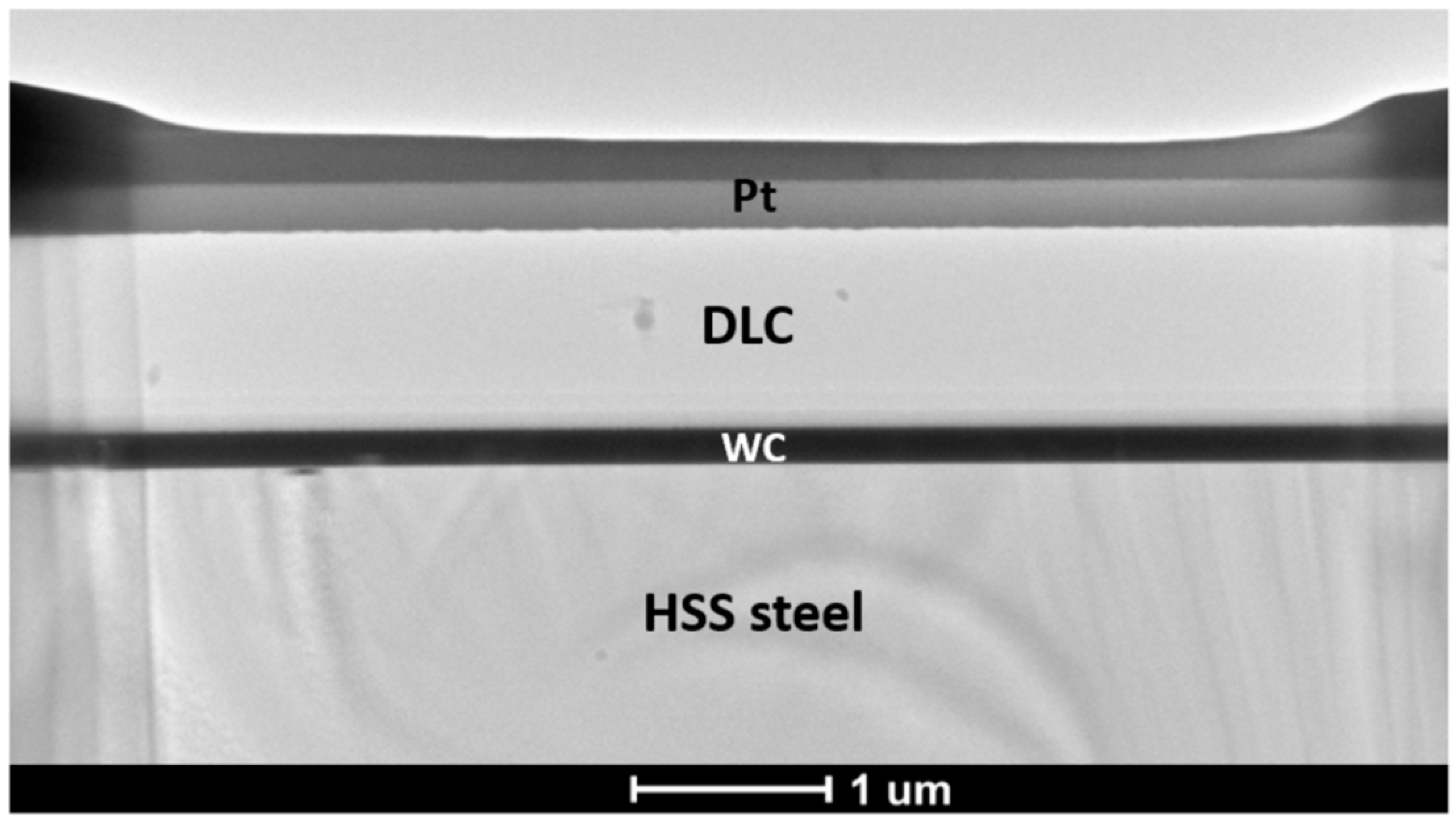
Finally, in order to obtain information about the layers, cross-section images were obtained by a FEI Verios 460 Field Emission XHR-SEM microscope (FEI, Hillsboro, OR, USA).

2.4. Mechanical and Tribological Tests

The adhesion assessment between the substrate and coatings was carried out with a CSM REVETEST Scratch tester fitted with a diamond Rockwell indenter (EURO 150518 C&N) with a tip radius of 200 µm. The test parameters that were used were a load rate of 100 N/min, a final load of 100 N, a speed of 9.58 mm/min and a total test length of 10 mm.
During the adhesion tests, different signals (penetration of the indenter within the substrate, acoustic emission, coefficient of friction) were recorded and the spots where the different events occurred were observed by optical microscopy. Using all this information, three different critical loads (LC) were registered:
  • The first critical load (LC1): the first cohesive failure observed;
  • The second critical load (LC2): the first adhesive failure appreciated;
  • The third critical load (LC3): a total delamination of the coating or even a critical defect is clearly observed in the reference substrate.
In the scratch tests, a progressive load is applied through the indenter on the surface of the samples, and while this load increases, different failure modes will appear. First, failure mechanisms, such as plastic deformation, fissurations for conformal type, fissurations of tensile or lateral fissurations, will be observed that are related to failure mechanisms of the cohesive type (Lc1). After this, failure mechanisms such as delaminations, fissurations by frontal deformation, superficial lifts or lateral chipping, among others, will appear, which are related to failure mechanisms of the adhesive type (Lc2). Finally, the applied load will be high enough to remove more than half of the coating from the substrate (Lc3).
A Microtest MT series equipment (Microtest S.A.) was used for the tribomechanical tests. Pin-on-disk tests were performed using 6mm alumina balls, each of which had a surface maximum roughness of Ramax = 0.050 µm and hardness of around 1650 HV, as the pins, and the different samples of coated and uncoated tools steels as the disks. The tests were carried out at a 40 N load, 200 rpm and 20,000 cycles, which supposes a Hertzian contact stress of 2.6 GPa. Tests were repeated three times at 8, 10 and 12 mm (track radii). As these are high performance tool steels and coatings with very good tribological properties, it was necessary to use a high load at enough revolutions to generate a measurable and homogeneous wear track. These conditions are more similar to the real cases of application of these coatings, such as cold stamping or forming applications, where high pressures are applied. Other studies have used similar parameters with this type of coatings [
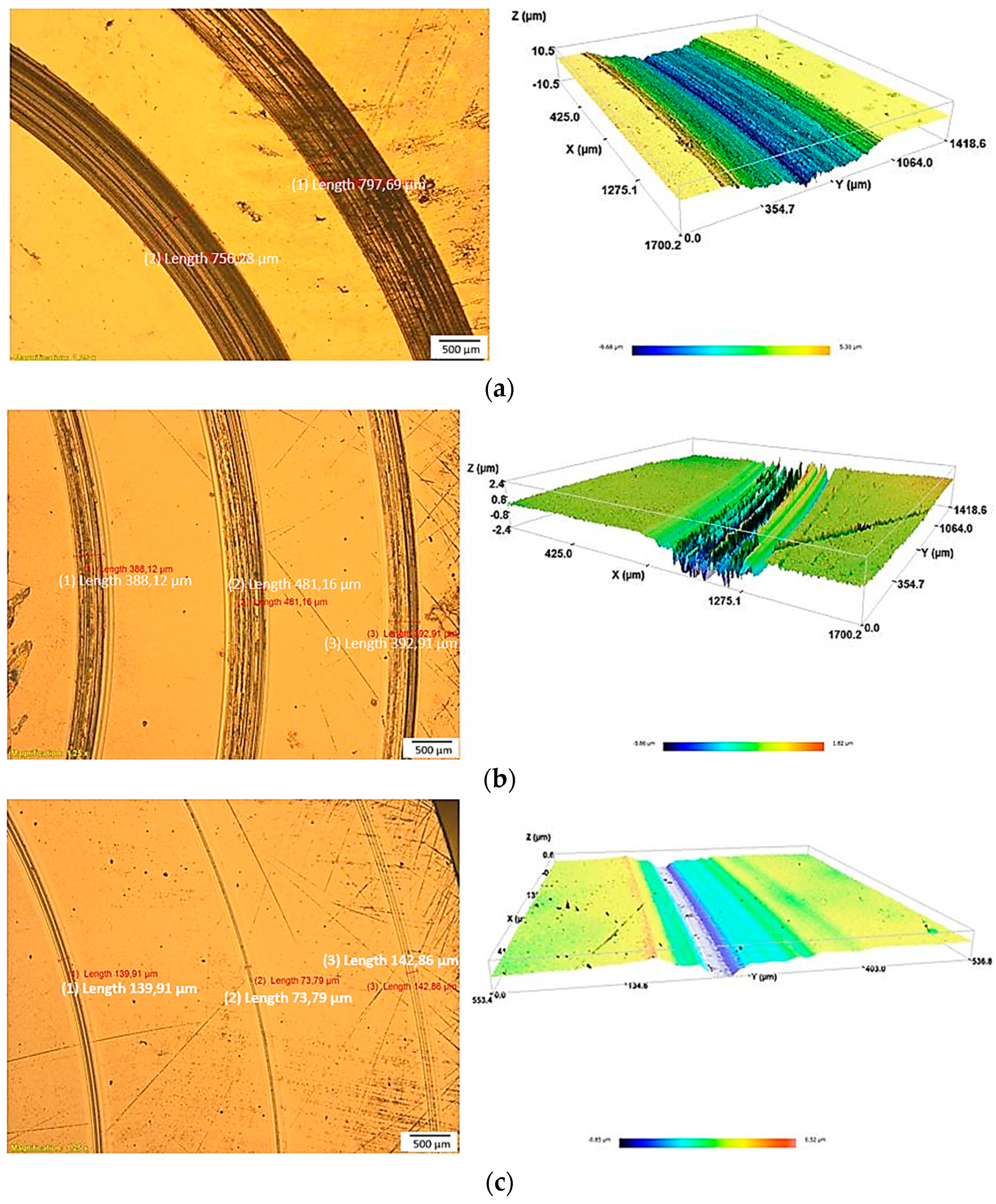
34]. The corresponding wear tracks have been measured by using a Confocal S mart Microscope (Sensofar) and an optical microscope. The volume loss as well as the wear evaluation were determined in two ways: according to ASTM G99 [49] and straight from the confocal measures of volume loss.
Nanohardness measurements were performed with an MTS NANOINDENTER XP fitted with a Berkovich tip, a maximum depth of 2000 nm and a maximum load of 25 mN. Hardness and Young’s modulus values were obtained by the Oliver and Pharr method [50] with the influence of the substrate in the hardness and Young’s modulus corrected using Bec et al.’s thin film model [51,52].

3. Results

3.1. Thickness, Structural Properties and Profile Composition

The calotest measurements that were carried out to determine the resultant thickness of the coating can be seen in Figure 2. The measurements of the calotest show several circumferences (marked in Figure 2 in red, yellow and orange) corresponding to different depth levels, caused by rolling the ball with abrasives during the test. The relationship between these dimensions allows the determination of the thickness of the coating. The results showed that the samples coated with ta-C have thicknesses of just about 1.65 µm; the samples coated with WC:C, instead, showed thicknesses of approximately 2 µm. These results are consistent with those obtained in the glow discharge optical emission spectrometry (GD-OES), shown in Figure 3.
Following with the GD-OES, the ta-C layer showed an approximate thickness of 1.5 µm. The weight percentage concentration in C was higher than 90% during the first 0.65 µm, followed by a WC layer of about 0.85 µm where the weight content of carbon decreased across the layer. An anchoring layer of 0.2 µm in chromium can also been observed, which has the aim of improving the adhesion to the substrate. On the other hand, the WC:C coating showed a thickness of around 1.75 µm composed by two different layers. For the first 0.75 µm in depth, a top carbon layer doped with W can be seen, containing 60% C and 40% W in weight. This layer is followed by a transition layer of about 1 µm in thickness than contains mainly W with the content of C decreasing across the layer from 60% in weight to less than 5%. As in the previous case, a chromium-anchoring layer of approximately 0.3 µm can also been observed before reaching the reference substrate.
Figure 4 shows the cross-section SEM picture of the coatings, where the different layers are schematically indicated. From bottom to top:
  • HSS substrate;
  • Cr bonding layer is not visible due to low resolution for observing 10 nm of thickness;
  • WC interlayer;
  • DLC coating;
  • Pt coating. There is a double layer of Pt coating on top. As the coating has been milled with FIB (focused ion beam) for cross-sectional (XS) observation, a Pt layer has been deposited on top in order to prevent the etching of the DLC coating due to ion irradiation.
Raman characterization was performed in order to evaluate the structural properties of DLC films. Raman spectra were recorded using a Renishaw’s inVia Qontor Raman microscope (Renishaw, Gloucestershire, UK). A green ion laser with a line of 532 nm was focused on the surface of the coatings with a power of 100 mW. The obtained Raman spectrum was curve-fitted using two Gaussian functions, peaking at disordered (D-band) and graphite (G-band) modes.
It is important to note that amorphous tetrahedral carbon (ta-C) structures have higher contents of sp3 bonds than amorphous carbon structures. The I(D)/I(G) ratio, which is shown in the Table 2, normally correlates with the sp2/sp3 fraction, so it was evaluated to check if the above statement is fulfilled. Therefore, it is expected that those structures that present a higher content of sp2 enhancements have a higher value for the I(D)/I(G) ratio [53]. In the samples analyzed, the highest value for this relationship was obtained for the K360 with WC:C case (with a value of 0.93), followed by the vanadis 4 with WC:C and vancron with WC:C samples (0.91). This means that these samples are the ones with the highest number of graphitic layers with sp2 bonds. On the other hand, for the K360, vancron and vanadis 4 with ta-C samples, the values obtained were 0.74, 0.71 and 0.69, respectively.
The presence of a D peak is consistent with the spectrum of aromatic hydrocarbons. Therefore, if a clear D peak is observed, it will be because of the ring’s breathing modes. However, on the contrary, not observing a D peak will mean that there is an absence of rings [53]. In the samples analyzed, in those coated with ta-C, peak D is less defined. Therefore, it can be assumed that they have fewer aromatic rings. Peaks G and D can be seen in Figure 5.
In turn, as previously mentioned, the sp3 concentration, the existence of a D peak, and therefore of aromatic rings, are related to the mechanical properties of the samples. Consequently, it could be assumed that those films that present a lower concentration of clustering achieve higher hardness.

3.2. Nanoindentation Tests

Figure 6 represents the nanoindentation tests up to a final load of 25 mN. As can be seen in the results, a specific hardness of 24 GPa was obtained for the ta-C coated K360 layer and 14 GPa for the WC:C coated one. In the case of the vanadis 4 layers, a specific hardness of 26 GPa was obtained for the ta-C coated layer, whereas a hardness of 14 GPa was reached for the WC:C layer.
The results of nanoindentation are similar to those reported by García et al. [34], showing values of 17 GPa for the WC:C coating and 30 GPa for ta-C. Duminica et al. [27] and Czyzniewski [54] also presented similar hardness values—between 21 and 23 GPa and 19 GPa, respectively.
In the load–displacement curves, a high elastic component can be observed for both type of coatings. The final depth was significantly greater for the WC:C coatings compared to the ta-C coatings. The corresponding hardness values, the Young modulus values and the relationship between hardness and modulus (H3/E2) are shown in Table 3. The value of H3/E2 is not very high in the coatings and it is especially low in the case of WC:C. Higher values were reported in other studies: García et al. [34] showed values of 0.15 for WC:C coatings and 0.45 for ta-C coatings, while Sun et al. [55] presented values between 0.243 and 0.263. The H3/E2 and H/E ratios, which relate the hardness and the Young modulus, are considered as indicators of resistance to plastic deformation in loaded contact and the elasticity index [56,57], respectively. Due to this, they are used to determine the toughness and the wear resistance of the coatings [56,58] since it is generally accepted that it is possible to adjust the wear resistance of a solid by adapting its elastoplastic properties, which could be summarized by increasing the hardness or decreasing the elastic modulus [59]. H3/E2 is related to the elastic limit of the material; therefore, it is expected that an increase in H3/E2 will lead to an improvement in the elastic recovery of the coating (a highly elastic behavior of the film under contact events), which is also related to the toughness [57,60,61]. It should be noted that, different studies conclude that parameters such as H/E and H3/E2 are more important than just hardness in determining the good wear resistance of a material and they highlight the importance of toughness in various tribological applications [56,57,58,62]. Theoretical analyses and research works have analyzed the relation between the parameter H3/E2 and the wear resistance, and they have proved that resistance to various forms of wear is correlated with the ratio H3/E2 [54,55,57,63]. Finally, it should be added that different investigations reported that the value of H3/E2 is related with the grain size of the nanostructure, so that the smallest grain size and highest fraction of phase boundaries lead to higher values of H3/E2 [57,58,64]. According to this, it can be said that the resistance to plastic deformation of the ta-C coating is higher than that of WC:C, and that, therefore, the wear resistance of ta-C should also be higher than that of WC:C.

3.3. Adhesion Tests

Scratch tests were performed on all the DLC coated specimens to evaluate their mechanical response and adhesion to the substrate. Figure 7 shows an example of the results obtained for the case of specimens with vanadis 4 as substrate (Figure 7a for the WC:C coating and Figure 7b for the ta-C coating); similar results were obtained in all cases. The acoustic emission (AE%) and the coefficient of friction (COF) establish a relationship between the normal and tangential forces, respectively, and they are represented in these figures. From these tests, the different failure modes along the scratches were evaluated and the critical loads at which they occurred were recorded. With the experimental results, it was possible to study the differences between the properties of the different coatings and substrates, with the objective of evaluating which one presents better adherence.
The results obtained from these adhesion tests were very positive for both coatings, even though clear differences were found between them. Table 4 summarizes the results of the three critical loads (Lc1, Lc2 and Lc3) recorded for each specimen. The samples coated with WC:C presented the first cohesive failure (Lc1) at about 19 N. The first adhesive failure (Lc2), instead, appeared at around 59 N in the vanadis 4 and vancron samples and at 32.9 N in the K360 sample, while the appearance of the substrate (Lc3) occurred at around 77 N in the vanadis 4 and vancron samples and a little bit earlier in the K360 sample—at 73.8 N. Looking at the Lc2 results, it is clear that the adhesion of the K360 steel is slightly worse than the other two steels with this coating. On the other hand, no cohesive failure was observed in any of the three ta-C coated samples; however, the results of Lc2 and Lc3 show that their adhesion was worse than the ones coated with WC:C. In these specimens, Lc2 was defined at about 25 N, whereas the Lc3 appeared at around 50 N in the K360 and vancron samples and at 40.3 N in the vanadis 4 sample. The addition of W to the DLC structure allows one to reduce compressive residual stress, as reported in [65]. A reduction in residual stress allows one to enhance adhesion critical load values despite showing lower values of hardness and wear resistance. As can be seen in Table 5, the adhesion results obtained in this study are higher than those reported in the references [26,27,66]. On the other hand, similar results of Lc2 were reported in reference [34], with ta-C and WC:C coatings, or in reference [67], showing Lc2 values up to 42 N to W-doped DLCs.

3.4. Friction and Wear Tests

A pin-on-disc tribometer was used to study the friction and wear properties of the DLC coatings as well as those of the reference substrates. The experimental results are shown in Figure 8. The coefficients of friction (COFs) are 0.7–0.8 for the uncoated samples. However, all the samples coated with ta-C showed a COF of around 0.07 which is lower than that shown by the samples coated with WC:C, which was around 0.1. The fluctuations in the COF curves during the run-in period are inherent to the test itself; during steady state, instead, they are related to the apparition of different tribo-oxidation bodies. Depending on test conditions, during the run-in period, it the formation of oxide phases in W-doped DLC coatings has been observed, which could lead to a higher COF before the formation of more lubricious graphitic tribolayers, as reported by [68]. This is the reason for obtaining higher friction in run-in period for the WC:C coatings than for the ta-C coating. The COF results are lower than those reported by Wang et al. [69], where values of COF between 0.12 and 0.21 for WC-DLC coatings are reported, or in reference [70], where values of 0.12–0.59 for DLC coatings on AISI H11 steels with plasma nitriding pretreatment are reported. However, similar results are reported in references [26,71].
Comparing the width of the wear tracks, it can be seen how clearly the wear has been greater for the uncoated samples. As shown in Figure 9, the width of the wear track measured in the uncoated samples takes values around 500–800 µm for the vancron and vanadis 4 samples and 1500–2000 µm for the case of the K360 specimen. The coated specimens, instead, present values close to 350 µm for the case of the WC:C coatings and 200 µm for those of ta-C. In all cases, the highest values were obtained for the K360 samples. From the images obtained by optical and confocal microscopy shown in Figure 9 the type of wear shown by each specimen can also be determined. Clear differences were observed between the type of wear for each coated sample. In the ta-C coated samples, very little abrasive wear was observed on the surface, while in the WC:C coated samples, typical microscratches were found. Despite the differences, it is clear that both coatings improve the wear resistance of the substrates—calculations made to determine the volume loss and wear coefficient will be shown in the paper and will show consistency with this statement.
The evaluation of the volume loss and the wear coefficient were carried out using two different methods. The first method consists of using the measurement of the width of the wear track and determining the values of volume loss and wear coefficient following what the ASTM G99 standard establishes. The standard determines the value of the volume loss for the entire track using the measured value of the wear track width. This result is then used to calculate the wear coefficient through a formula that relates it to the applied load in the test and the total sliding distance, thus obtaining a normalized value for the wear coefficient. The second method, however, consists of calculating the volume loss directly using the confocal microscope and the Sensoview program, and then extrapolating that value for the entire wear track using the equation shown in formula (1). Then, the wear coefficient value is calculated using the same equation as in the first method.
V   loss   c o n f o c a l   ( m 3 ) w e a r   t r a c k   l e n g t h   ( m )   ×   2   ×   П   ×   r   ( m )   =   V   loss   ( m 3 )
Table 6 shows a summary of the results of the friction coefficient and volume loss and wear coefficient calculated with both ASTM G99 and confocal microscopy of each tested sample. The values shown are the average values of the tests carried out with different test radii; the test parameters are the same for all of them. The results obtained by both methods show a similar trend, but there is a difference of one order of magnitude between them. This difference is due to the fact that the calculation carried out following the ASTM G99 standard assumes that the shape of the wear track is that of a perfect sphere, while by confocal measures the real shape of the wear track is taken. The results obtained in both cases show that the highest values of volume loss and wear coefficients were achieved for the uncoated specimens and the smallest for those coated with ta-C. Following the ASTM G99 standard, values of wear coefficient of around 1.7 × 10⁻⁵ mm3/Nm were obtained for the vancron and vanadis 4 uncoated samples, while the K360 sample presented a worse wear resistance with a coefficient of 4.87 × 10⁻⁴ mm3/Nm. The same trend was observed in the case of results obtained by confocal measures, with values of the order of 10−6 mm3/Nm for the specimens of vancron and vanadis 4 and of 10−5 mm3/Nm for that of K360. DLC coated samples showed values up to two orders of magnitude lower in comparison to the reference substrates. Values of about 2.3 × 10⁻⁶ mm3/Nm were obtained for the WC:C coatings measured following the ASTM G99 and between 4.98 × 10⁻⁷ and 7.44 × 10⁻⁷ mm3/Nm for the confocal measures. As previously mentioned, the best wear resistance was presented by the ta-C coatings, with wear coefficients of 3.51 × 10⁻⁷ mm3/Nm (vancron), 5.29 × 10⁻⁷ mm3/Nm (K360) and 7.17 × 10⁻⁸ mm3/Nm (vanadis 4) for the ASTM G99 measures, and 7.59 × 10⁻⁸ mm3/Nm (vancron), 5.37 × 10⁻⁸ mm3/Nm (vanadis 4) and 6.72 × 10⁻⁸ mm3/Nm (K360) for the confocal measures. The wear coefficient results obtained for the WC:C coating are similar to those reported in reference [72], with values of 1.11 × 10⁻⁶ mm3/Nm for the N-DLC coating or 1.88 × 10⁻⁶ mm3/Nm for the DLC sample, or reference [54], showing values of 2.1 × 10⁻⁶ mm3/Nm. As mentioned above, the ta-C coating showed better wear resistance than the WC:C coating, and similar results were reported by García et al. [34] (order of magnitude of 10−8 mm3/Nm), by Sun et al. [55] (6.37 × 10⁻⁸ mm3/Nm) and by Kasirowski et al. [26] (6.52 × 10⁻⁸ mm3/Nm non-nitrided substrate and 4.79 × 10⁻⁸ mm3/Nm nitrided sample).
Figure 10 and Figure 11 present a comparative graph of the values related to wear coefficient calculated by ASTM G99 (orange bars) and confocal measures (blue bars), showing good repeatability of the tribological tests. A difference of about an order of magnitude between the two methods is evident in these figures.

4. Discussion

Once all the tests on the samples coated with different DLCs by HiPIMS with positive pulses have been carried out, it is possible to highlight some of their aspects. First of all, Raman spectroscopy showed how the specimens coated with ta-C show a greater number of sp3 hybrid bonds than those of WC:C. This is consistent with the values obtained in the nanohardness tests and shows the importance of the sp2/sp3 ratio to determine the hardness. The nanohardness values obtained coincide with those shown in previous studies, with higher values of hardness for the ta-C samples than for the WC:C ones.
It should also be noted that by doping the coating with W (WC:C) it is possible to increase its adhesion properties due to the decrease in the surface energy. This is demonstrated by the results of Lc2 and Lc3, where the coating of WC:C presents values of around 59 and 75 N, respectively, while for the ta-C coating values of about 25 N for Lc2 and 50 N for Lc3 are reported. In this aspect, k360 steel exhibits a worse performance than the other two since the first adhesive failure appears at a critical load of 32.9 N, which is considerably lower than in the others. The efficacy of the novel HiPIMS with positive pulses technique is also demonstrated, with a clear improvement in the adhesion of the coatings to the substrates.
The resistance to plastic deformation (H3/E2) showed lower values than those found in the literature; specifically, values of around 0.15 were obtained for the ta-C coating and 0.04 for the WC:C coating. However, these values show concordance with those obtained for wear resistance since the higher the value of H3/E2, the better the resistance to wear of the coatings. The wear coefficient values show how for ta-C values of the order of 10−8 mm3/Nm were obtained; on the other hand, for WC:C, values of the order of 10−7 mm3/Nm were obtained (measured by the confocal microscope). As already stated, the effect of doping the coating with W (WC:C) is also evident in these results. The addition of W to the DLC structure allows the reduction of the compressive residual stress, enhancing adhesion critical load values, but also affects the hardness and wear resistance of the coatings, showing lower values of hardness and wear resistance. The COF values of the WC:C coatings are higher than the ta-C ones, and they show higher friction during the run-in period due to the formation of oxide phases.
Comparing the results obtained for the different substrates, it can be said that powder metallurgical steels show better properties than the ESR steel. This statement is demonstrated with the adhesion results (Lc2 for WC:C) and the values obtained for the wear resistance.
Finally, it should be noted that the slight discrepancies (about an order of magnitude) showed in the wear rate measurements with both different methods—following the ASTM G99 standard and the confocal directly—can be associated with the fact that the wear tracks do not have perfect spherical shapes due to the small wear suffered by the alumina balls during the pin-on-disc tests. This could lead to the values obtained by confocal measures being lower but more realistic.

5. Conclusions

In this work, high quality tools steels have been coated with advanced DLC coatings by using the novel HiPIMS technique with positive pulses. The objective of this work was to find the best results for the most extreme and demanding applications, and for this type of application, steels such as those that have been studied are commonly used. With this technique, tribological properties of great interest were obtained, such as a great resistance to wear or resistance to plastic deformation, in addition to improving the adhesion of the coating with the substrate. After analyzing the experimental procedure that was carried out and the results obtained, some aspects can be highlighted:
  • Raman spectroscopy showed that ta-C coatings have a higher number of sp3 bonds, which is consistent with these coatings being harder than those of WC:C;
  • The nanohardness of coatings was around 25 Gpa for the ta-C and around 14 GPa for the WC:C coating;
  • The relationship between resistance to plastic deformation and resistance to wear was proven, since the higher values of H3/E2 correlated with higher values of resistance to wear. It should be noted that this is a sign that hardness is not the only parameter that determines the wear behavior of coatings;
  • The coefficient of friction (COF) against alumina was considerably lower than that of the substrate (0.7) in the case of both coatings in all materials, obtaining values of around 0.07 for the ta-C coating and 0.1 for the WC:C coating;
  • The coatings showed very good adhesion to the substrate. The coatings of WC:C presented better results than those of ta-C, reaching values greater than 70 N for the critical load LC3. Vanadis 4 and vancron presented better adhesion than K360, as shown by the Lc2 values obtained for the WC:C coating;
  • The two coatings improve the wear resistance of the substrate, as demonstrated by the values obtained for volume loss and wear coefficient, especially for the case of ta-C. The WC:C coatings showed wear coefficient values one order of magnitude lower than the substrate (10−7), while in the case of ta-C values, values two orders of magnitude lower than the substrate were achieved (10−8).
The experimental results show that these DLC coatings obtained by the novel HiPIMS technique with positive pulses are a great option for implementation at an industrial level and are capable of competing with other types of coatings with which they could not do so until now.
If the results obtained for the different substrates are compared, it can be seen that the adhesion of powder metallurgical steels is greater than the ESR steels, while the first adhesive failure (Lc2) appears later with the WC:C coating in the case of the these steels (32.9 N for K360 and near 59 N for the powder metallurgical steels). A better trend in the results obtained for the wear coefficient for these steels can be observed, as shown in the comparative graphs. This better behavior could be due to their higher quality, which is characterized by a better dimensional stability, greater homogeneity of carbides and greater mechanical properties such as toughness or yield strength. Although further studies are necessary to determine the cause of this better behavior, these properties could lead into lower and more homogeneous residual stress in the substrate, resulting in lower strain on the interface substrate coating, and a greater ability to withstand the loads transmitted through the coating. A greater chemical compatibility seems to be another factor that affects the adhesion between the coating and the substrate and the higher content in vanadium in powder metallurgical steels could increase the yield strength of the steel, which could explain the better behavior against loads.

Author Contributions

Conceptualization, J.A.G., A.C., J.A.S., I.F., J.F.P., and E.B.; formal analysis, J.A.G. and A.C.; investigation, A.C., J.A.G., E.J.-P., E.A., J.F.P., J.F.d.A., and J.A.S.; resources, E.B.; writing—original draft preparation, A.C. and J.A.G.; writing—review and editing, A.C., J.A.G., E.J.-P., J.F.P., J.F.d.A., and J.A.S.; supervision, J.A.G.; project administration, J.A.G.; funding acquisition, E.J.-P. and J.A.G. All authors have read and agreed to the published version of the manuscript.

Funding

Funded in part by the Spanish Ministry of Science, Innovation and Universities through grant PGC2018-096855-B-C41, PGC2018-096855-B-C43 and PGC2018-096855-A-C44.

Data Availability Statement

Data is contained within the article.

Acknowledgments

AIN acknowledges the support of CDTI Ministerio de Ciencia e Innovación of Spain through the project CERVERA (CER2019-1003).

Conflicts of Interest

The authors declare no conflict of interest.

References

  1. Donnet, C.; Erdemir, A. New horizon in the tribology of diamondlike carbon films. Surf. Eng. 2008, 24, 399–401. [Google Scholar] [CrossRef] [Green Version]
  2. Erdemir, A.; Donnet, C. Tribology of diamond-like carbon films: Recent progress and future prospects. J. Phys. D Appl. Phys. 2006, 39. [Google Scholar] [CrossRef]
  3. Pierson, H.O. Handbook of Carbon, Graphite, Diamond and Fullerenes: Properties, Processing and Applications; Noyes Publication: Park Ridge, NJ, USA, 1993. [Google Scholar]
  4. Robertson, J. Diamond-like amorphous carbon. Mater. Sci. Eng. R 2002, 37, 129–281. [Google Scholar] [CrossRef] [Green Version]
  5. Bewilogua, K.; Hofmann, D. History of diamond-like carbon films—From first experiments to worldwide applications. Surf. Coat. Technol. 2014, 242, 214–225. [Google Scholar] [CrossRef]
  6. Bull, S.J. Tribology of carbon coatings: DLC, diamond and beyond. Diam. Relat. Mater. 1995, 4, 827–836. [Google Scholar] [CrossRef]
  7. Saxena, P.; Schinzel, M.; Andrich, M.; Modler, N. Development of a novel test-setup for identifying the frictional characteristics of carbon fibre reinforced polymer composites at high surface pressure. Mater. Sci. Eng. 2016, 149, 012124. [Google Scholar] [CrossRef]
  8. Rodríguez, R.J.; Garcı́a, J.A.; Martinez, R.; Lerga, B.; Rico, M.; Fuentes, G.G.; Guette, A.; Labruguere, C.; Lahaye, M. Tribological metal-carbon coatings deposited by PVD magnetron sputtering. Appl. Surf. Sci. 2004, 235, 53–59. [Google Scholar] [CrossRef]
  9. Dai, M.; Zhou, K.; Yuan, Z.; Ding, Q.; Fu, Z. The cutting performance of diamond and DLC-coated cutting tools. Diam. Relat. Mater. 2000, 9, 1753–1757. [Google Scholar] [CrossRef]
  10. Fukui, H.; Okida, J.; Omori, N.; Moriguchi, H.; Tsuda, K. Cutting performance of DLC coated tools in dry machining aluminum alloys. Surf. Coat. Technol. 2004, 187, 70–76. [Google Scholar] [CrossRef]
  11. Silva, F.; Martinho, R.P.; Alexandre, R.; Baptista, A. Increasing the wear resistance of molds for injection of glass fiber reinforced plastics. Wear 2011, 271, 2494–2499. [Google Scholar] [CrossRef] [Green Version]
  12. Hauert, R.; Thorwarth, K.; Thorwarth, G. An overview on diamond-like carbon coatings in medical applications. Surf. Coat. Technol. 2013, 233, 119–130. [Google Scholar] [CrossRef]
  13. Treutler, C.P.O. Industrial use of plasma-deposited coatings for components of automotive fuel injection systems. Surf. Coat. Technol. 2005, 200, 1969–1975. [Google Scholar] [CrossRef]
  14. Novikov, N.V.; Gontar, A.G.; Khandozhko, S.I.; Kutsay, A.M.; Tkach, V.N.; Gorokhov, V.Y.; Belitsky, G.M.; Vasinc, A.V. Protective diamond-like coatings for optical materials and electronic devices. Diam. Relat. Mater. 2000, 9, 792–795. [Google Scholar] [CrossRef]
  15. Morshed, M.M.; McNamara, B.P.; Cameron, D.C.; Hashmi, M.S.J. Stress and adhesion in DLC coatings on 316L stainless steel deposited by a neutral beam source. J. Mater. Process. Technol. 2003, 141, 127–131. [Google Scholar] [CrossRef]
  16. Mosaner, P.; Bonelli, M.; Miotello, A. Pulsed laser deposition of diamond-like carbon films: Reducing internal stress by thermal annealing. Appl. Surf. Sci. 2003, 208–209, 561–565. [Google Scholar] [CrossRef]
  17. Neuville, S.; Matthews, A. A perspective on the optimisation of hard carbon and related coatings for engineering applications. Thin Solid Films 2007, 515, 6619–6653. [Google Scholar] [CrossRef]
  18. Silva, S.R.P. (Ed.) Properties of Amorphous Carbon; The Institution of Engineering and Technology: London, UK, 2008; pp. 311–312. [Google Scholar]
  19. McWilliams, A. Diamond, Diamond-Like and CBN Films & Coating Products. BCC Res. 2010, 7, 160. [Google Scholar]
  20. Ghiotti, A.; Bruschi, S. Tribological behaviour of DLC coatings for sheet metal forming tools. Wear 2011, 271, 2454–2458. [Google Scholar] [CrossRef]
  21. Sgarabotto, F.; Ghiotti, A.; Bruschi, S. Novel experimental set-up to investigate the wear of coatings for sheet metal forming tools. Key Eng. Mater. 2013, 554–557, 825–832. [Google Scholar] [CrossRef]
  22. Helmersson, U.; Lattemann, M.; Bohlmark, J.; Ehiasarian, A.; Gudmundsson, J.T. Ionized physical vapor deposition (IPVD): A review of technology and applications. Thin Solid Films 2006, 513, 1–24. [Google Scholar] [CrossRef] [Green Version]
  23. Santiago, J.; Fernández-Martínez, I.; Kozák, T.; Capek, J.; Wennberg, A.; Molina-Aldareguia, J.; Bellido-González, V.; González-Arrabal, R.; Monclús, M.A. The influence of positive pulses on HiPIMS deposition of hard DLC coatings. Surf. Coat. Technol. 2019, 358, 43–49. [Google Scholar] [CrossRef]
  24. Bhushan, B. Modern Tribology Handbook; Boca Raton (Fla.); CRC Press: Boca Raton, FL, USA, 2001; pp. 102–136. [Google Scholar]
  25. Wang, Q.J.; Chung, Y.-W. Encyclopedia of Tribology; Springer US: Boston, MA, USA, 2013; pp. 794–800. [Google Scholar]
  26. Kasiorowski, T.; Lin, J.; Soares, P.; Lepienski, C.M.; Neitzke, C.A.; de Souza, G.B.; Torres, R.D. Microstructural and tribological characterization of DLC coatings deposited by plasma enhanced techniques on steel substrates. Surf. Coat. Technol. 2019, 389, 125615. [Google Scholar] [CrossRef]
  27. Duminica, F.-D.; Belchi, R.; Libralesso, L.; Mercier, D. Investigation of Cr(N)/DLC multilayer coatings elaborated by PVD for high wear resistance and low friction applications. Surf. Coat. Technol. 2018, 337, 396–403. [Google Scholar] [CrossRef]
  28. Shioga, P.H.T.; Binder, C.; Hammes, G.; Klein, A.N.; de Mello, J.D.B. Effects of Different Plasma Nitrided Layers on the Tribological Performance of DLC Coatings. Mater. Res. 2016, 19, 1180–1188. [Google Scholar] [CrossRef] [Green Version]
  29. Podgornik, B.; Vižintin, J. Influence of substrate treatment on the tribological properties of DLC coatings. Diam. Relat. Mater. 2001, 10, 2232–2237. [Google Scholar] [CrossRef]
  30. Marin, E.; Lanzutti, A.; Nakamura, M.; Zanocco, M.; Zhu, W.; Pezzotti, G.; Andreatt, F. Corrosion and scratch resistance of DLC coatings applied on chromium molybdenum steel. Surf. Coat. Technol. 2019, 378, 124944. [Google Scholar] [CrossRef]
  31. Avelar-Batista, J.C.; Spain, E.; Fuentes, G.G.; Sola, A.; Rodriguez, R.; Housden, J. Triode plasma nitriding and PVD coating: A successful pre-treatment combination to improve the wear resistance of DLC coatings on Ti6Al4V alloy. Surf. Coat. Technol. 2006, 201, 4335–4340. [Google Scholar] [CrossRef]
  32. Liu, L.; Wu, Z.; An, X.; Shao, T.; Xiao, S.; Cui, S.; Lin, H.; Fu, R.K.Y.; Tian, X.; Chu, P.K.; et al. Improved interfacial adhesion between TiAlN/DLC multi-layered coatings by controlling the morphology via bias. Surf. Coat. Technol. 2017, 331, 15–20. [Google Scholar] [CrossRef]
  33. Santiago, J.A.; Fernández-Martínez, I.; Wennberg, A.; Molina-Aldareguia, J.M.; Castillo-Rodríguez, M.; Rojas, T.C.; Sánchez-López, J.C.; González, M.U.; García-Martín, J.M.; Li, H.; et al. Adhesion enhancement of DLC hard coatings by HiPIMS metal ion etching pretreatment. Surf. Coat. Technol. 2018, 349, 787–796. [Google Scholar] [CrossRef]
  34. García, J.A.; Rivero, P.J.; Barba, E.; Fernández, I.; Santiago, J.A.; Palacio, J.F.; Fuente, G.G.; Rodríguez, R.J. A Comparative Study in the Tribological Behavior of DLC Coatings Deposited by HiPIMS Technology with Positive Pulses. Metals 2020, 10, 174. [Google Scholar] [CrossRef] [Green Version]
  35. Tobola, D.; Brostow, W.; Czechowski, K.; Rusek, P. Improvement of wear resistance of some cold working tool steels. Wear 2017, 382–383, 29–39. [Google Scholar] [CrossRef]
  36. Kim, H.; Kang, J.-Y.; Son, D.; Lee, T.-H.; Cho, K.-M. Evolution of carbides in cold-work tool steels. Mater. Charact. 2015, 107, 376–385. [Google Scholar] [CrossRef]
  37. Kanga, J.-Y.; Kima, H.; Sonc, D.; Kimd, C.; Park, S.K.; Lee, T.-H. Hot-worked microstructure and hot workability of cold-work tool steels. Mater. Charact. 2018, 135, 8–17. [Google Scholar] [CrossRef]
  38. Fukaura, K.; Sunada, H.; Yokoyama, Y.; Teramoto, K.; Yokoi, D.; Tsujii, N. Improvement of strength and toughness of SKD11 type cold work tool steel. Tetsu-to-Hagané 1998, 84, 230–235. [Google Scholar] [CrossRef]
  39. Fukaura, K.; Yokoyama, Y.; Yokoi, D.; Tsujii, N.; Ono, K. Fatigue of cold-work tool steel: Effect of heat treatment and carbide morphology on fatigue crack formation, life, and fracture surface observation. Metall. Mater. Trans. A 2004, 35, 1289–1300. [Google Scholar] [CrossRef]
  40. Arieta, F.; Netto, E.B.M.; Reguly, A.; Pannes, W.K.; Beutler, U.; van Soest, F.; Ernst, C. Impact properties of vacuum heat treated AISI D2 and 8%Cr-cold work tool steels. J. ASTM Int. 2011, 8, 129–145. [Google Scholar] [CrossRef]
  41. Picas, I.; Cuadrado, N.; Casellas, D.; Goez, A.; Llanes, L. Microstructural effects on the fatigue crack nucleation in cold work tool steels. Proc. Eng. 2010, 2, 1777–1785. [Google Scholar] [CrossRef]
  42. Arslan, F.K.; Altinsoy, I.; Hatman, A.; Ipek, M.; Zeytin, S.; Bindal, C. Characterization of cryogenic heat treated Vanadis 4 PM cold work tool steel. Vacuum 2011, 86, 370–373. [Google Scholar] [CrossRef]
  43. Oppenkowski, A.; Weber, S.; Theisen, W. Evaluation of factors influencing deep cryogenic treatment that affect the properties of tool steels. J. Mater. Process. Technol. 2010, 210, 1949–1955. [Google Scholar] [CrossRef]
  44. Riofano, R.M.M.; Casteletti, L.C.; Canale, L.C.F.; Totten, G.E. Improved wear resistance of P/M tool steel alloy with different vanadium contents after ion nitriding. Wear 2008, 265, 57–64. [Google Scholar] [CrossRef]
  45. Ko, D.-C.; Kim, S.-G.; Kim, B.-M. Influence of microstructure on galling resistance of cold-work tool steels with different chemical compositions when sliding against ultra-high-strength steel sheets under dry condition. Wear 2015, 338–339, 362–371. [Google Scholar] [CrossRef]
  46. Gåård, A.; Krakhmalev, P.; Bergström, J. Wear mechanisms in deep drawing of carbon steel—Correlation to laboratory testing. Lubr. Sci. 2008, 14, 1–9. [Google Scholar] [CrossRef]
  47. Kim, H.; Han, S.; Yan, Q.; Altan, T. Evaluation of tool materials, coatings and lubricants in forming galvanized advanced high strength steels (AHSS). CIRP Ann. Manuf. Technol. 2008, 14, 299–304. [Google Scholar] [CrossRef]
  48. García, J.A.; Rodríguez, R.J.; Martínez, R.; Fernández, C.; Fernández, A.; Payling, R. Depth profiling of industrial surface treatments by rf and dc glow discharge spectrometry. Appl. Surf. Sci. 2004, 235, 97–102. [Google Scholar] [CrossRef]
  49. ASTM G99-17. Standard Test Method for Wear Testing with a Pin-on-Disk Apparatus; American Society for Testing and Materials: West Conshohocken, PA, USA, 2017. [Google Scholar]
  50. Oliver, W.C.; Pharr, G.M. An improved technique for determining hardness and elastic modulus using load and displacement sensing indentation experiments. J. Mater. Res. 1992, 7, 1564–1583. [Google Scholar] [CrossRef]
  51. Bec, S.; Tonck, A.; Loubet, J.L. A simple guide to determine elastic properties of films on substrate from nanoindentation experiments. Philos. Mag. 2006, 86, 5347–5358. [Google Scholar] [CrossRef] [Green Version]
  52. Botero, C.; Jimenez-Pique, E.; Seuba, J.; Kulkarni, T.; Sarin, V.; Llanes, L. Mechanical behavior of 3Al2O3·2SiO2 films under nanoindentation. Acta Mater. 2012, 60, 5889–5899. [Google Scholar] [CrossRef]
  53. Ferrari, A.C.; Robertson, J. Interpretation of Raman spectra of disordered and amorphous carbon. Phys. Rev. B 2000, 61, 14095–14107. [Google Scholar] [CrossRef] [Green Version]
  54. Czyzniewski, A. Optimising deposition parameters of W-DLC coatings for tool materials of high speed steel and cemented carbide. Vacuum 2012, 86, 2140–2147. [Google Scholar] [CrossRef]
  55. Sun, W.; Li, M.; Wu, M.; Hu, J. Uniformity of Si-containing diamond-like carbon films deposited at different positions by mesh hollow cathode discharge. Results Phys. 2019, 14, 102480. [Google Scholar] [CrossRef]
  56. Leyland, A.; Matthews, A. On the significance of the H/E ratio in wear control: A nanocomposite coating approach to optimised tribological behaviour. Wear 2000, 246, 1–11. [Google Scholar] [CrossRef]
  57. Charitidis, C.A. Nanomechanical and nanotribological properties of carbon-based thin films: A review. Int. J. Refract. Hard Met. 2010, 28, 51–70. [Google Scholar] [CrossRef]
  58. Galvan, D.; Pei, Y.T.; De Hosson, J.T.M. Deformation and failure mechanism of nano-composite coatings under nano-indentation. Surf. Coat. Technol. 2006, 200, 6718–6726. [Google Scholar] [CrossRef] [Green Version]
  59. Lopes, B.B.; Rangel, R.C.C.; Antonio, C.A.; Durrant, S.F.; Cruz, N.C.; Rangel, E.C. Mechanical and Tribological Properties of Plasma Deposited a-C:H:Si:O Films; Nanoindentation in Materials Science IntechOpen: London, UK, 2012; pp. 179–202. [Google Scholar]
  60. Charitidis, C.; Logothetidis, S.; Douka, P. Nanoindentation and nanoscratching studies of amorphous carbon films. Diam. Relat. Mater. 1999, 8, 558–562. [Google Scholar] [CrossRef]
  61. Le Bourhis, E. Indentation mechanics and its application to thin film characterization. Vacuum 2008, 82, 1353–1359. [Google Scholar] [CrossRef]
  62. Mayrhofer, P.H.; Mitterer, C.; Musil, J. Structure–property relationships in single- and dual-phase nanocrystalline hard coatings. Surf. Coat. Technol. 2003, 174–175, 725–731. [Google Scholar] [CrossRef]
  63. Wang, L.; Li, L.; Kuang, X. Effect of substrate bias on microstructure and mechanical properties of WCDLC coatings deposited by HiPIMS. Surf. Coat. Technol. 2018, 352, 33–41. [Google Scholar] [CrossRef]
  64. Luo, H.; Sun, H.; Gao, F.; Billard, A. Mechanical properties, thermal stability and oxidation resistance of HfC/a-C:H films deposited by HiPIMS. J. Alloys Compd. 2020, 847, 156538. [Google Scholar] [CrossRef]
  65. Sánchez-López, J.C.; Fernández, A. Doping and Alloying Effects on DLC Coatings. In Tribology of Diamond-Like Carbon Films; Donnet, C., Erdemir, A., Eds.; Springer: Boston, MA, USA, 2008; pp. 311–338. [Google Scholar]
  66. Moreno-Bárcenas, A.; Alvarado-Orozco, J.M.; Carmona, J.M.G.; Mondragón-Rodríguez, G.C.; González-Hernández, J.; García-García, A. Synergistic effect of plasma nitriding and bias voltage on the adhesion of diamond-like carbon coatings on M2 steel by PECVD. Surf. Coat. Technol. 2019, 374, 327–337. [Google Scholar] [CrossRef] [Green Version]
  67. Cao, L.; Liu, J.; Wan, Y.; Pu, J. Corrosion and tribocorrosion behavior of W doped DLC coating in artificial seawater. Diam. Relat. Mater. 2020, 109, 108019. [Google Scholar] [CrossRef]
  68. Voevodin, A.A.; O’Neill, J.P.; Zabinski, J.S. Tribological performance and tribochemistry of nanocrystalline WC/amorphous diamond-like carbon composites. Thin Solid Films 1999, 342, 194–200. [Google Scholar] [CrossRef]
  69. Wang, L.; Lin, J.; Zhu, C.; Li, G.; Kuang, X.; Huang, K. Effects of HiPIMS pulse-length on plasma discharge and on the properties of WC-DLC coatings. Appl. Surf. Sci. 2019, 487, 526–538. [Google Scholar] [CrossRef]
  70. Tillman, W.; Lopes Dias, N.; Stangier, D. Influence of plasma nitriding pretreatments on the tribo-mechanical properties of DLC coatings sputtered on AISI H11. Surf. Coat. Technol. 2019, 357, 1027–1036. [Google Scholar] [CrossRef]
  71. Makówka, M.; Pawlak, W.; Konarski, P.; Wendler, B.; Szymanowski, H. Modification of magnetron sputter deposition of nc-WC/a-C(:H) coatings with an additional RF discharge. Diam. Relat. Mater. 2019, 98, 107509. [Google Scholar] [CrossRef]
  72. Bouzakis, K.-D.; Vidakis, N.; Michailidis, N.; Leyendecker, T.; Erkens, G.; Fuss, G. Quantification of properties modification and cutting performance of (Ti1−xAlx)N coatings at elevated temperatures. Surf. Coat. Technol. 1999, 120–121, 34–43. [Google Scholar] [CrossRef]
Figure 1. Cross-section of the process chamber.
Coatings 11 00028 g001
Figure 2. Calotest craters used to determine the resultant thickness for the tetrahedral amorphous carbon (ta-C) coated sample (a) and tungsten carbide:carbon (WC:C) coated sample (b). The different circumferences correspond to the different rings exposed after the abrasion of the coating with the balls used for the calculation of the different thicknesses.
Coatings 11 00028 g002
Figure 3. Glow discharge optical emission spectrometry (GD-OES) concentration profiles in the sample of ta-C coating (a) and WC:C coating (b).
Coatings 11 00028 g003
Figure 4. Cross-section SEM picture with the coating’s structure.
Coatings 11 00028 g004
Figure 5. Raman spectra of all the coated samples.
Coatings 11 00028 g005
Figure 6. Nanoindentation curves for a specific final load of 25 mN in the K360 with ta-C coating (blue plot), vanadis 4 with ta-C coating (orange plot), K360 with WC:C coating (grey plot) and vanadis 4 with WC:C coating (yellow plot).
Coatings 11 00028 g006
Figure 7. Example of the scratch test results. Evolution of the coefficient of friction (blue plot) and acoustic emission (orange plot) vs. the indenter displacement and the normal force: WC:C coated vanadis 4 sample (a) and ta-C coated vanadis 4 sample (b).
Coatings 11 00028 g007aCoatings 11 00028 g007b
Figure 8. Friction coefficient of vanadis 4 coated and uncoated samples (a), K360 coated and uncoated samples (b) and vancron coated and uncoated samples (c), respectively.
Coatings 11 00028 g008aCoatings 11 00028 g008b
Figure 9. Example of the aspect of the wear tracks obtained after the friction and wear tests, obtained by optical microscopy (left) and confocal microscopy (right), for the uncoated vanadis 4 sample (a), vanadis 4 with WC:C sample (b) and vanadis 4 with ta-C sample (c).
Coatings 11 00028 g009
Figure 10. Comparative graph of the values related to wear coefficient calculated by both methods for the uncoated samples.
Coatings 11 00028 g010
Figure 11. Comparative graph of the values related to wear coefficient calculated by both methods for the ta-C and WC:C coated samples.
Coatings 11 00028 g011
Table 1. Chemical composition of the 3 tools’ steels studied in this work (wt.%).
SteelC (%)Si (%)Cr (%)N (%)V (%)Mn (%)Mo (%)
K3601.250.98.75-1.180.352.7
Vanadis 41.40.44.7-3.70.43.5
Vancron1.31.84.51.810--
Table 2. Summary of the experimental data derived from the Raman spectroscopy.
Substrate and CoatingG(cm−1)I (G)D(cm−1)I (D)I (D)/I (G)
K360 WC:C1.5735.7041.3605.31370.93
K360 ta-C1.52712.1921.3269.0580.74
Vanadis 4 ta-C1.52113.0581.3269.0580.69
Vanadis 4 WC:C1.5689.2401.3818.40570.91
Vancron WC:C1.5608.1551.3837.4460.91
Vancron ta-C1.5366.2061.3284.4290.71
Table 3. Summary of the experimental data derived from the nanoindentation curves such as the resultant hardness (H), Young modulus (E) and the H3/E2 relationship, respectively.
SubstrateDLC CoatingHardness (GPa)Young Modulus (GPa) H 3 / E 2
K360ta-C24 ± 3311 ± 270.148
K360WC:C14 ± 1257 ± 220.043
Vanadis 4ta-C26 ± 2343 ± 300.152
Vanadis 4WC:C15 ± 2277 ± 270.041
Table 4. Summary of the critical load values obtained for each sample from the scratch test.
Substrate and CoatingLc1 (N)Lc2 (N)Lc3 (N)
K360 WC:C18.9 ± 0.732.9 ± 0.673.8 ± 4.0
Vanadis 4 WC:C19.2 ± 0.458.8 ± 1.377.6 ± 2.3
Vancron WC:C19.0 ± 2.159.8 ± 0.777.1 ± 3.9
K360 ta-C-29.6 ± 2.550.7 ± 3.7
Vanadis 4 ta-C-25.0 ± 3.140.3 ± 1.1
Vancron ta-C-24.4 ± 4.250.4 ± 5.4
Table 5. Summary of the critical load Lc2 values obtained for each reference from the scratch test.
ReferenceCoatingDeposition TechniqueLc2 (N)
[26]DLCNitrided substrate + HiPIMS25
[27]Cr(N)/DLC multilayerDC magnetron sputtering10
[34]ta-CHiPIMS with positive pulses18.86
[34]WC:CHiPIMS with positive pulses40.87
[66]DLCPlasma-enhanced chemical vapordeposition (PECVD)12
[67]W-doped DLCDC magnetron sputtering42
Table 6. Summary of the experimental data of friction coefficient, volume loss and wear coefficient measured by ASTM G99 and confocal for reference substrates, ta-C coatings and WC:C coatings.
SampleFriction Coefficient Volume   Loss   ( m 3 )   ASTM   G 99 Volume   Loss   Confocal   ( m 3 ) Wear   Coefficient   ASTM   G 99   ( mm 3 / Nm ) Wear   Coefficient   Confocal   ( mm 3 / Nm )
Uncoated vancron0.67(9.64 ± 10) × 10−10(2.67 ± 2.7) × 10−10(1.73 ± 1.69) × 10−5(4.88 ± 4.1) × 10−6
Uncoated vanadis 40.71(7.73 ± 1.5) × 10−10(1.64 ± 0.48) × 10−10(1.70 ± 0.06) × 10−5(3.62 ± 0.47) × 10−6
Uncoated K3600.76(1.21 ± 1.05) × 10−8(4.64 ± 6.1) × 10−10(4.87 ± 0.77) × 10−4(1.31 ± 0.54) × 10−5
Vancron WC:C0.097(1.08 ± 0.38) × 10−10(2.43 ± 0.1) × 10−11(2.30 ± 1.28) × 10−6(4.98 ± 1.04) × 10−7
Vanadis 4 WC:C0.15(1.16 ± 0.41) × 10−10(3.44 ± 1.08) × 10−11(2.35 ± 0.84) × 10−6(6.79 ± 1.51) × 10−7
K360 WC:C0.112(1.12 ± 0.24) × 10−10(3.65 ± 0.73) × 10−11(2.24 ± 0.34) × 10−6(7.44 ± 1.89) × 10−7
Vancron ta-C0.067(1.74 ± 0.67) × 10−11(3.85 ± 1.14) × 10−12(3.51 ± 1.33) × 10−7(7.59 ± 1.34) × 10−8
Vanadis 4 ta-C0.07(3.60 ± 2.93) × 10−12(2.66 ± 0.29) × 10−12(7.17 ± 5.5) × 10−8(5.37 ± 0.53) × 10−8
K360 ta-C0.105(2.65 ± 0.73) × 10−11(3.43 ± 1.05) × 10−12(5.29 ± 1.1) × 10−7(6.72 ± 0.72) × 10−8
Publisher’s Note: MDPI stays neutral with regard to jurisdictional claims in published maps and institutional affiliations.

