Article

Synthesis of the Porous ZnO Nanosheets and TiO2/ZnO/FTO Composite Films by a Low-Temperature Hydrothermal Method and Their Applications in Photocatalysis and Electrochromism

1
School of Light Industry, Harbin University of Commerce, Harbin 150028, China
2
State Key Laboratory of High-Efficiency Utilization of Coal and Green Chemical Engineering, Ningxia University, Ningxia 750021, China
3
Center for Composite Materials and Structure, Harbin Institute of Technology, Harbin 150001, China
4
Research Centre for Materials Science and Engineering, Guangxi University of Science and Technology, Liuzhou 545006, China
*
Authors to whom correspondence should be addressed.
Coatings 2022, 12(5), 695; https://doi.org/10.3390/coatings12050695
Submission received: 28 March 2022 / Revised: 16 May 2022 / Accepted: 17 May 2022 / Published: 19 May 2022
(This article belongs to the Special Issue Smart Coatings for Energy Saving Applications)

Abstract

:
In this paper, porous zinc oxide (ZnO) nanosheets were successfully prepared by a simple low-temperature hydrothermal method. X-ray diffraction (XRD), scanning electron microscopy (SEM), transmission electron microscopy (TEM) and Brunauer–Emmett–Teller (BET) tests showed that the synthesized product was ZnO with porous sheet structure. The diameter of porous nanosheets was about 100 nm and the thickness was about 8 nm. As a photocatalyst, the degradation efficiencies of porous ZnO nanosheets for methyl orange (MO), methylene blue (MB) and Rhodamine B (RhB) were 97.5%, 99% and 96.8%, respectively. In addition, the degradation efficiency of ZnO for mixed dyes (Mo, MB and RhB) was satisfactory, reaching 97.7%. The photocatalytic stability of MB was further tested and remained at 99% after 20 cycles. In the experiment, ZnO/FTO (fluorine-doped tin oxide) composites were prepared by using ZnO as the conductive layer. Titanium dioxide (TiO2) was deposited on the surface of ZnO/FTO by electrodeposition, so as to obtain a TiO2/ZnO/FTO composite. By studying the electrochromic properties of this composite, it was found that the TiO2/ZnO/FTO composite shows a large light modulation range (55% at 1000 nm) and excellent cycle stability (96.6% at 200 cycles). The main reason for the excellent electrochromic properties may be the synergistic effect between the porous structure and the polymetallic oxides. This study is helpful to improve the photocatalytic efficiency and cycling stability of metal oxides, improve the transmittance of thin films and provide a new strategy for the preparation of ZnO composite materials with excellent photocatalytic and electrochromic properties.

1. Introduction

With the rapid development of modern society, energy consumption is becoming more and more significant. Energy consumption has become a problem that must be solved in social development. At the same time, the use of coal, oil and other fossil energy and the discharge of wastewater in the production process are causing serious environmental pollution. Therefore, green and efficient utilization methods have become a research hotspot in the field of energy and environment. To achieve the goal of low-carbon, energy-saving, green and sustainable development, it is important to develop high-performance green energy-saving devices, realize the efficient use of sunlight and change the current energy consumption structure [1,2].
In recent years, ZnO semiconductor materials have received widespread attention due to their simple and diverse preparation methods, easy operation, high conductivity and excellent photocatalytic performance. ZnO materials have a variety of nanostructures and a large bandgap. The catalytic decomposition efficiency of pollutants is very good. Due to its high sunlight utilization [3,4,5], ZnO has become the most likely photocatalyst to replace TiO2 and has become one of the most popular photocatalysts. ZnO has higher conductivity because it can carry more electrons and holes when given external energy. Therefore, by mixing ZnO with other substances, a semiconductor material with good conductivity can be obtained, which plays an excellent role in material devices [6]. ZnO can also be used to detect gas. The main principle is that the resistivity of a semiconductor device changes due to changes in the surrounding gas [7]. This allows us to accurately detect the most harmful gases, further improving the quality of life. ZnO materials are also commonly applied in many areas such as quantum dot solar cells, photocatalysts, light-emitting LEDs, and electrochromism conductive layers. Ngullie et al. [8] successfully prepared ZnO nanocomposites by pyrolysis of urea and thiourea; the material was very effective in photocatalytic degradation of MB, and the material could effectively degrade 98% of MB dyes within 180 min. Lu et al. [9] synthesized ZnO NPs using the root extract of lanceolate and found that the material can effectively degrade 90.2% of MB in 40 min, and the cycle stability can reach 95% after 10 experiments. Qamar et al. [10] synthesized a G-C3N4/Cr-ZnO hybrid nanocomposite. The composite showed a significant enhancement in solar energy utilization, and was able to effectively degrade 93% of methylene blue dye within 90 min. Ali et al. [11] successfully fabricated ZnO nanofilms by thermal evaporation, which had a transmittance of more than 50% at 870 nm. Yang et al. [12] successfully prepared double-layer ZnO nanobricks by a two-step hydrothermal method and the RF sputtering method, with a reaction time of 12.8 s and a coloring efficiency of 18.28 cm2 c1. After 2000 cycles, the capacity retention rate reached 60.3%.
In this work, we prepared porous ZnO nanostructures by a simple low-temperature hydrothermal method. We studied their photocatalytic and electrochromic properties. The results show that the length and thickness of nano-flake porous structures are about 100 nm and 8 nm, respectively. We further studied the photocatalytic decomposition and electrochromic properties of the prepared materials. Through the photocatalytic performance test, the material has suitable degradation efficiency for MO, MB and RhB. Through the electrochromic performance test, the material has light transmittance in the visible near-infrared band, and the transmittance value is 55% at the wavelength of about 1000 nm. After 200 cycles in the 550 nm visible band and the 1000 nm near-infrared band, the stability of the material remains 96.8% in the near-infrared band and 45% in the visible band. This indicates that the TiO2/ZnO/FTO composite has better stability in the infrared band. By referring to the relevant literature and analyzing the experimental results, there are many influential factors. (1) The effect of particle size: Grain size determines if there is a quantum size effect. Grain size indirectly affects photocatalytic efficiency because the quantum size effect can effectively improve photocatalytic efficiency [13,14,15]. (2) The influence of the surface area: Under certain conditions such as lattice defects, the surface area is proportional to the photocatalytic activity. At the same time, some of the electrons and holes with a large surface area will overlap and produce a recombination effect. When the recombination effect is large, the result is opposite, and the surface area is inversely proportional to the catalytic activity [16,17]. (3) Effect of adsorption effect: The strength of adsorption capacity is closely related to the specific surface area of semiconductor nanoparticles. The adsorption area is proportional to the ability to adsorb organic pollutants, and then to the photocatalytic decomposition effect [18]. (4) Electrical conductivity of the material itself. (5) The influence of light: The light source determines the quality and uniformity of light, among which the light intensity has the greatest influence. The light intensity determines the number of photons irradiated onto the surface of the photocatalyst, determines the high-energy hole electron logarithm formed by the exciting transition of semiconductor electrons and ultimately determines the performance of the catalyst (the light intensity is proportional to the photocatalytic degradation effect of pollutants) [19,20].
The products prepared by low-temperature hydrothermal and electrodeposition methods in this paper have favorable photocatalytic and electrochromic properties. This study will contribute to the realization of multifunctional applications of materials, and provide a new approach and method to solve the problems of energy shortage and environmental pollution, which will have wide application prospects in the future.

2. Materials and Methods

2.1. Preparation of 2D Porous ZnO Nanosheets

Zn(NO3)2·6(H2O) was purchased from Shanghai Collaman Reagent Co., Ltd. (Shanghai, China) and the product purity reached 99%. Na2CO3 was purchased from Weifang Haizhiyuan Chemical Co., LTD. (Shandong, China). The purity of the product reached 99.2%. First, we weighed 2.97 g of Zn(NO3)2·6(H2O) solid and 1.06 g of Na2CO3 solid into different beakers, then added 20 mL of deionized water to the two beakers and poured the Na2CO3 solution into zinc nitrate solution. Magnetic stirring was carried out at room temperature for 1 h, and then 1.0 g sustained-release agent hexamethylenetetramine (HMT) was added to the solution and stirred continuously for 1 h. Then, the above-mixed solution was transferred to a 100 mL Teflon-lined stainless-steel autoclave and heated at 150 °C for 12 h. After completing the reaction, cooling to room temperature and opening the reaction kettle, the reaction kettle substrate generated white precipitate. After the temperature of the reactor cooled to room temperature, the white precipitated material was repeatedly cleaned with ethanol and water, and then centrifuged at 600 rpm for 0.5 h to obtain the white precipitated material. After cleaning, the white precipitate was transferred to an oven at 45 °C for drying until it was completely dried. After 12 h, the white precipitate was transformed into a white powder. The obtained material was further heated at 350 °C in a muffle furnace and calcined for 3 h. Finally, the porous structure material of ZnO was obtained, as shown in Figure 1.

2.2. Preparation of ZnO/FTO Composite Film

The experimental procedure of preparing ZnO thin film by the hydrothermal method on FTO conductive glass substrate is as follows: Transfer the above-mentioned ZnO precursor to the hydrothermal and put the cleaned FTO conductive glass at an angle followed by heated at 60 °C for 12 h. After the temperature is naturally cooled, take out the FTO glass, wash and dry to obtain a white film sample covering the FTO conductive surface and finally put the white film sample covering the FTO glass at 350 °C. After annealing for 3 h, samples of the annealed ZnO/FTO composite film were obtained.

2.3. The Experimental Procedure of Preparing TiO2/ZnO Composite Film

The nanostructured TiO2 film was grown on the ZnO/FTO-coated glass substrate using a hydrothermal method as follows: 1 g of polyethylene oxide-polypropylene oxide-polyethylene oxide (PEO-PPO-PEO) was added to 40 mL of anhydrous ethanol and stirred at room temperature for 30 min, and then dispersed ultrasonically for 30 min to form a transparent solution. After that, 40 mL of concentrated hydrochloric acid (HCl) was added and stirred for 30 min, followed by adding 0.85 mL of titanium isopropoxide into the solution. The solution was subsequently transferred to a 100 mL Teflon-lined stainless steel autoclave. The ZnO/FTO was placed inside the autoclave with the FTO layer facing the bottom. The hydrothermal process was carried out at 120 °C for 8 h in an electric oven and then cooled down to room temperature. The obtained TiO2/ZnO/FTO film was washed with deionized rinse and dried in an oven at 60 °C for 4 h.

3. Results

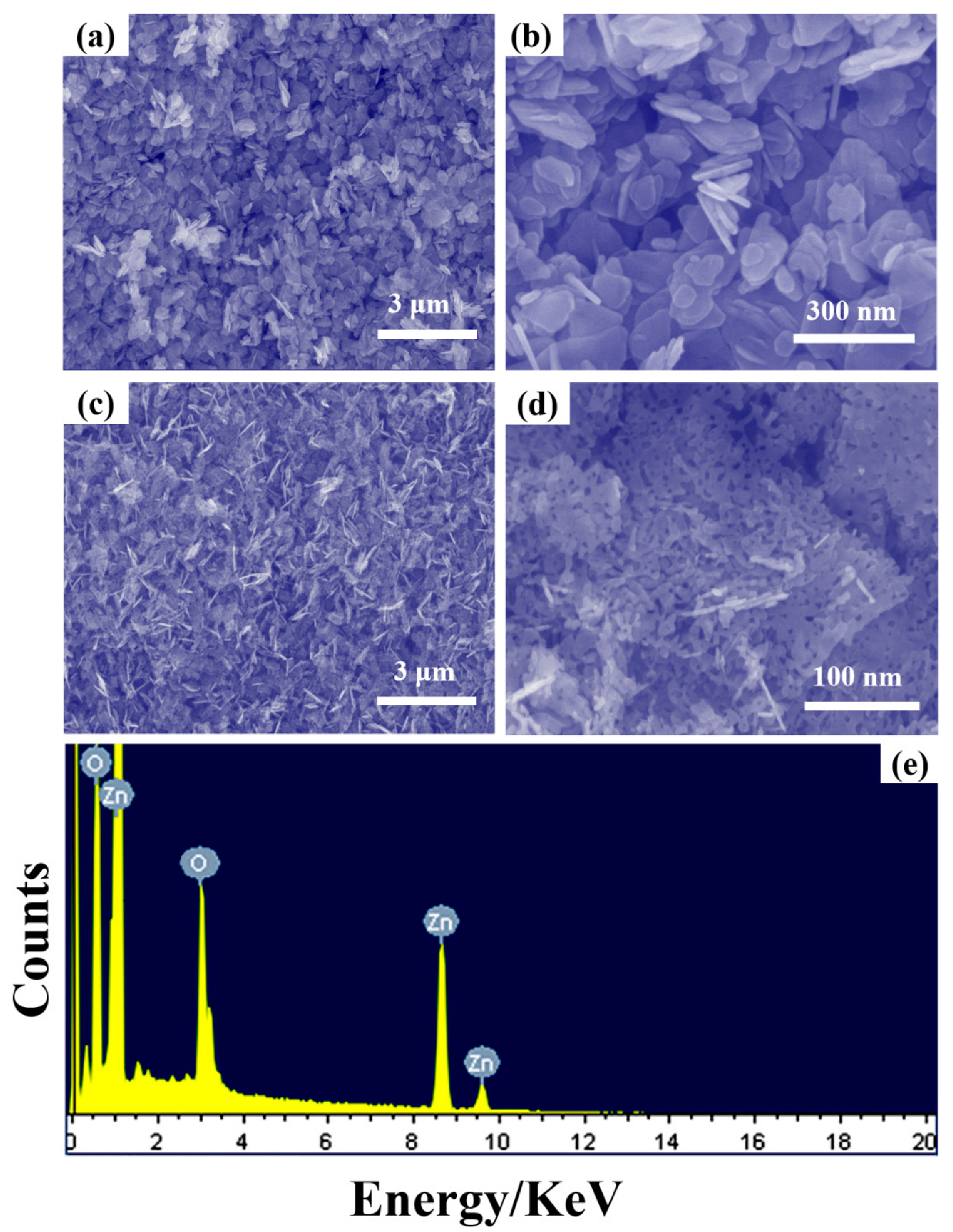
Figure 2 shows SEM images of porous ZnO nanosheets. Figure 2a is a low-power scanning electron micrograph of the untreated composite. Many nanosheet structures can be found, which are uniform in morphology and have almost no difference in size. As can be seen from Figure 2b, the length of the synthesized nanosheet is 100–150 nm, and the holes are formed by structural accumulation of each other. When the product is hydrothermally treated, as shown in Figure 2c, it can be seen that the synthesized material is still in a sheet-like structure. In order to observe the products more carefully, we conducted a high-magnification SEM test on the material. As shown in Figure 2d, the size of ZnO nanomaterials after hydrothermal treatment is significantly reduced, and there are many holes in the nanosheets, forming ZnO porous nanosheets. Figure 2e is an SEM element spectrum. It can be found from the figure that only two elements exist, Zn and O, indicating that the prepared product is pure zinc oxide without impurities.
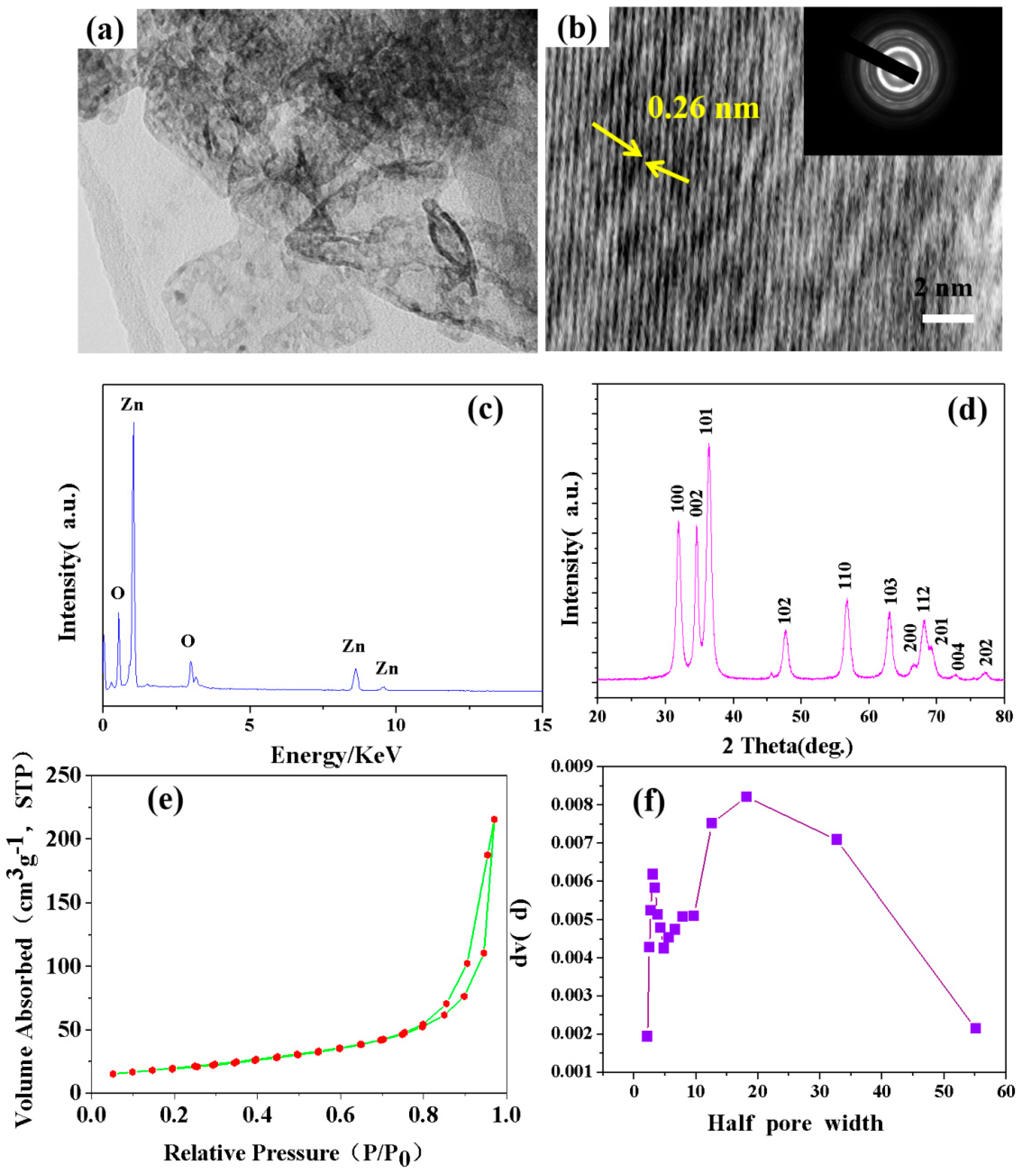
In order to further observe the microstructure of the material, we carried out a TEM test on the ZnO porous nanosheets, as shown in Figure 3. Figure 3a is the low-magnification TEM image of ZnO, and we can clearly see that the size of the sheet-like structure is around 100 nm. Figure 3b is a high-resolution transmission electron microscope image. It can be seen from the figure that the lattice spacing of the material is 0.26 nm, and it grows along the growth direction of the (002) crystal plane. The inset in the upper right corner of Figure 3b is the selected area electron diffraction test, and it can be seen that the ZnO nanosheets are polycrystalline materials. Figure 3c shows the energy spectrum analysis of ZnO nanosheets, which only contain zinc and oxide elements, indicating that the synthesized product is ZnO without impurities. Figure 3d shows the XRD test of the ZnO nanosheets. The diffraction peaks (100), (002), (101), (102), (110), (103) and (200) are all characteristic peaks of ZnO, which are consistent with the PDF card (JCPDS No. 36-1451), indicating that the synthesized product is ZnO, consistent with the above analysis. Figure 3e contains the nitrogen adsorption and desorption curves of ZnO nanosheets. Through analysis, its specific surface area is 170.94 m2 g−1. The large specific surface area facilitates the shortening of the electron diffusion path and speeds up the reaction [21,22]. Figure 3f shows the pore size distribution curve. It can be seen from the figure that the pores around 5 nm are the pores of the zinc oxide nanosheets themselves. The pores between 10 and 50 nm are the pores formed by interlacing between materials.
Compared with other technologies, photocatalytic technology has the characteristics of environmental protection, cheap, stable and reusable, and has excellent performance in sewage treatment and air pollution; thus, it is considered a promising environmental remediation technology. Nano-sized zinc oxide (ZnO) has the application characteristics of non-toxicity, easy preparation, low cost and controllable surface properties, and has good adsorption effects on both heavy metal ions and organic pollutants, and its structure has a great influence on the adsorption effect; in general, the larger the specific surface area, the higher the adsorption capacity and better the degradation effect. The same metal oxide nanomaterials are synthesized by different methods, and their particle size and surface chemistry will be different; factors such as pH and temperature during experimental testing impact the final results [23].
Adsorption is the first step in the photocatalytic reaction. High adsorption efficiency is beneficial for the photocatalytic reaction, and the defects can be used as active sites for the photocatalytic reaction. Under the conditions of 20 °C, initial concentration of dye C0 = 40 mg/L, pH = 2 and catalyst dosage of 0.1 g, we investigated the effect of contact time between the photocatalyst and the three dyes on the adsorption amount, as shown in Figure 4. According to the figure analysis, the zinc oxide catalyst has a fast adsorption speed for MO, MB and RhB dyes, and the removal rate reaches about 80% in the first 40 min of the initial adsorption stage. The adsorption rates of MO, MB and RhB reached 98.2%, 94.7% and 96.7%, respectively, when the adsorption equilibrium was reached. At the initial stage of the reaction, the zinc oxide surface has a large number of unoccupied surface sites for adsorption; at this time, the adsorption rate is fast. However, with the increase in adsorption capacity, the dye molecules adsorbed on the surface of the material and the dye molecules in the solution produce a repulsive force, which makes the remaining empty surface sites difficult to occupy, leading to the saturation of adsorption capacity [24].
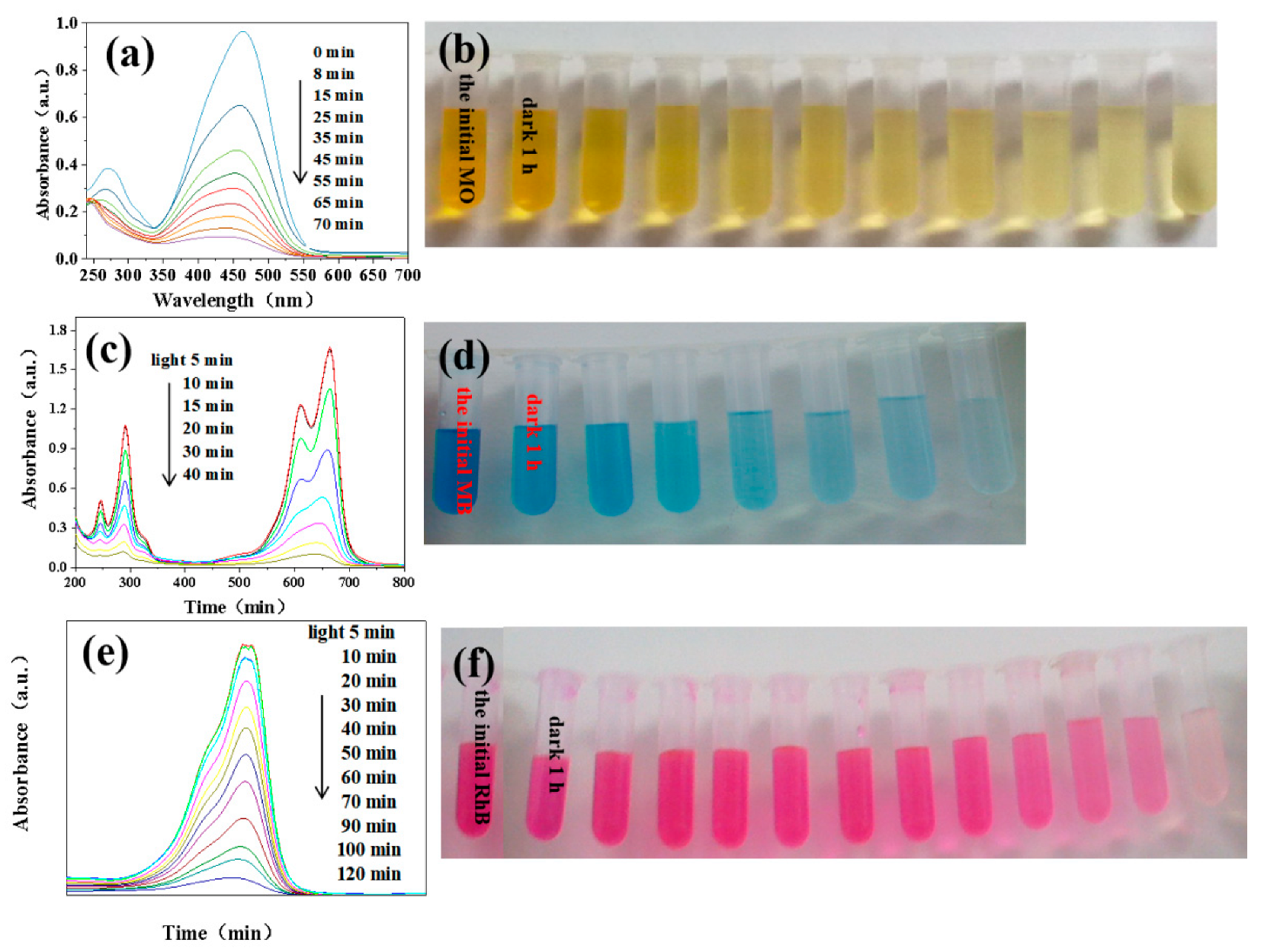
Among many photocatalytic materials, ZnO nanomaterials in metal oxides have a relatively large area, and zinc oxide is non-toxic and odorless. In recent years, it has been widely used as a photocatalyst to degrade organic dyes [25,26]. In order to analyze the photocatalytic degradation efficiency of our prepared ZnO nanosheets, we tested the material to degrade MO, MB and RhB dyes at room temperature, with light irradiance of 0.23 mW/cm2 and pH = 2. The concentration of dye was 40 mg/L, and the mass of zinc oxide was 0.1 g. We placed each dye in a centrifuge tube, put 0.1 g of zinc oxide into each dye solution, stirred in the dark for 1 h to reach the equilibrium of adsorption and desorption and took the equilibrium solution again in a centrifuge tube. The solution after reaching the equilibrium of adsorption and desorption was irradiated with ultraviolet light with a 500 W Hg lamp, and the solution was taken on time. After the degradation was completed, centrifugation was performed, and finally, the supernatant was taken for UV analysis and testing. The data are shown in Figure 5. Figure 5a is a graph of the degradation of MO and the degradation percentage in 90 min is 97.5%. Figure 5b shows the degradation curve of MB, and the degradation rate reached 98.5% in 40 min.
Figure 5e shows the degradation curve of RhB; the degradation rate reached 96.8% in 120 min. Figure 5b,d,f are photos of the degraded dyes. From the pictures, we can clearly see that the color of the dyes becomes lighter as time increases, and finally almost transparent, indicating that the dyes become degraded. [27,28]. From the relationship between the light absorption threshold of the semiconductor and the bandgap, K = 1240/Eg(eV). Most of the thresholds for wide-bandgap semiconductors commonly used in daily life are in the UV region.
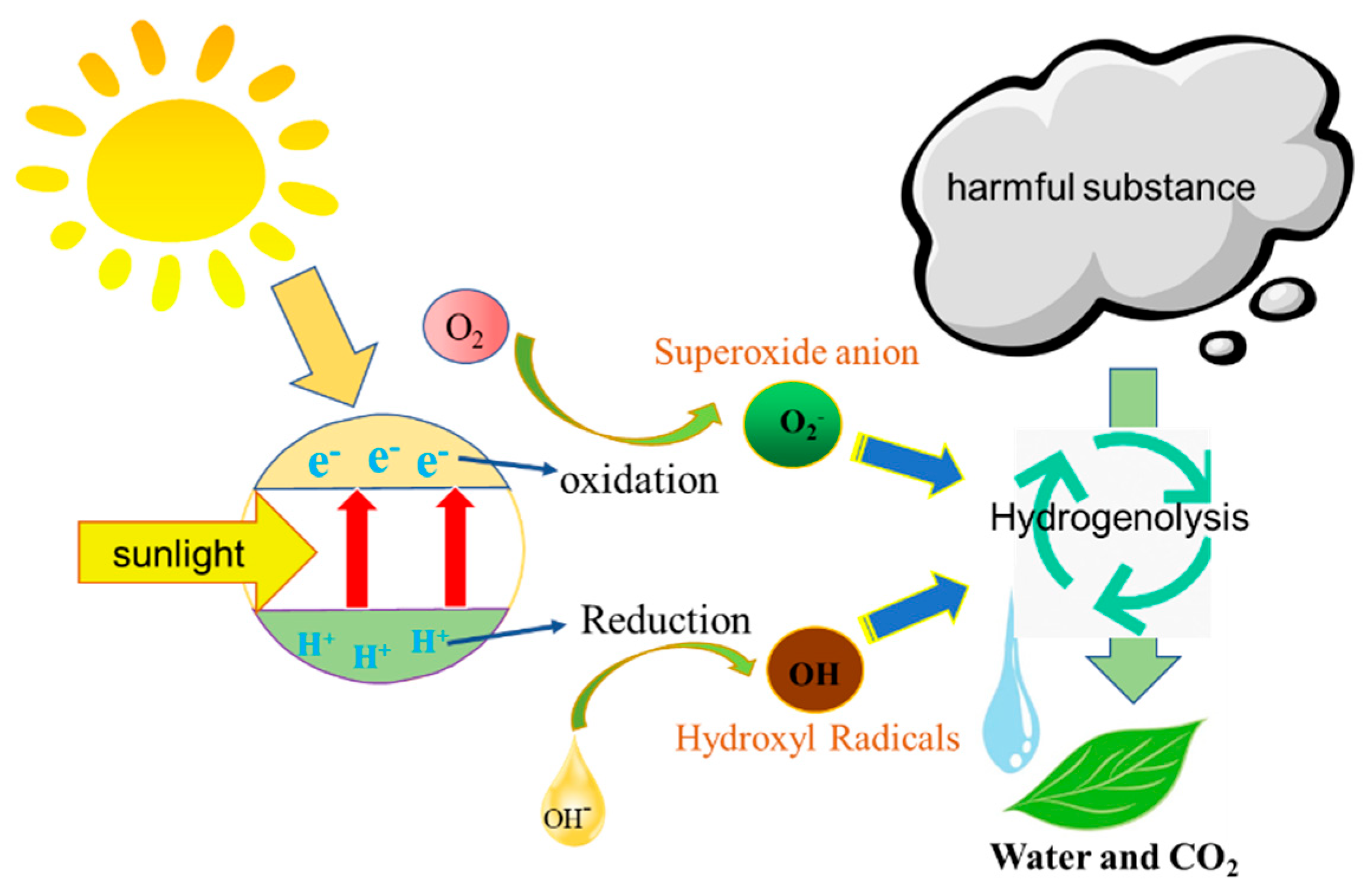
The degradation study of dyes by ZnO was further explored in the experiment. As a photocatalyst, when irradiated at a certain wavelength, the valence band electrons of the semiconductor are energized and undergo inter-band leap, which is a leap from the valence band to the conduction band, resulting in an equal amount of photogenerated electrons (E) and an equal amount of holes (H+) [29]. At this time, the dissolved oxygen adsorbed on the surface of nanomaterials in solution can easily capture electrons and combine to form superoxide anions. At the same time, the holes have a certain oxidation ability, and the hydroxyl ions (OH) adsorbed on the surface of the catalyst and water are oxidized to form hydroxyl radical (OH·). Superoxide anions (O2−) and hydroxyl radicals (OH·) have strong oxidizing properties, which can oxidize most organic substances to produce inorganic products CO2 and H2O, and even some inorganic substances can be completely oxidized and decomposed [30,31]. The corresponding chemical equation of the reaction is as follows, and the photocatalytic mechanism is illustrated in Figure 6.
ZnO + HV → h+ + e
h+ + OH → OH·
h+ + H2O → OH· + H+
e + O2 → O2
O2 + e + 2H → H2O2
O2 + H+ → H2O
2HO2·→ O2 + H2O2
H2O2 + e→ ·OH + OH
H2O2 + O2 → ·OH + OH + O2
O2/·OH + org → degraded + products
To compare which dyes had a better degradation effect under the same dye concentration and light conditions, the degradation rate curve was made at the same time for 40 min, as shown in Figure 7a. It could be seen that MB was the fastest, MO was the second fastest, and RhB was the slowest: RhB (42%) < MO (81%) < MB (98.5%). We further explored the degradation efficiency of the material after mixing three dyes: MO, MB and RhB. The results are shown in Figure 7b, which illustrates that the degradation effect is satisfactory, reaching 97.7%.
To further investigate whether the synthesized material has recyclable properties, each decomposition-catalyzed sample was recycled, reused and decomposed again and the dye MB was periodically decomposed. A total of 20 cycles were tested, with the same test conditions and initial dye decomposition process. The results show that the material degrading dyes are relatively stable with 99% degradation efficiency, as shown in Figure 8.
A variety of composite nanomaterials have improved degradation efficiency and cycle stability. Table 1 shows the comparison of the catalytic performance of each catalyst and references.
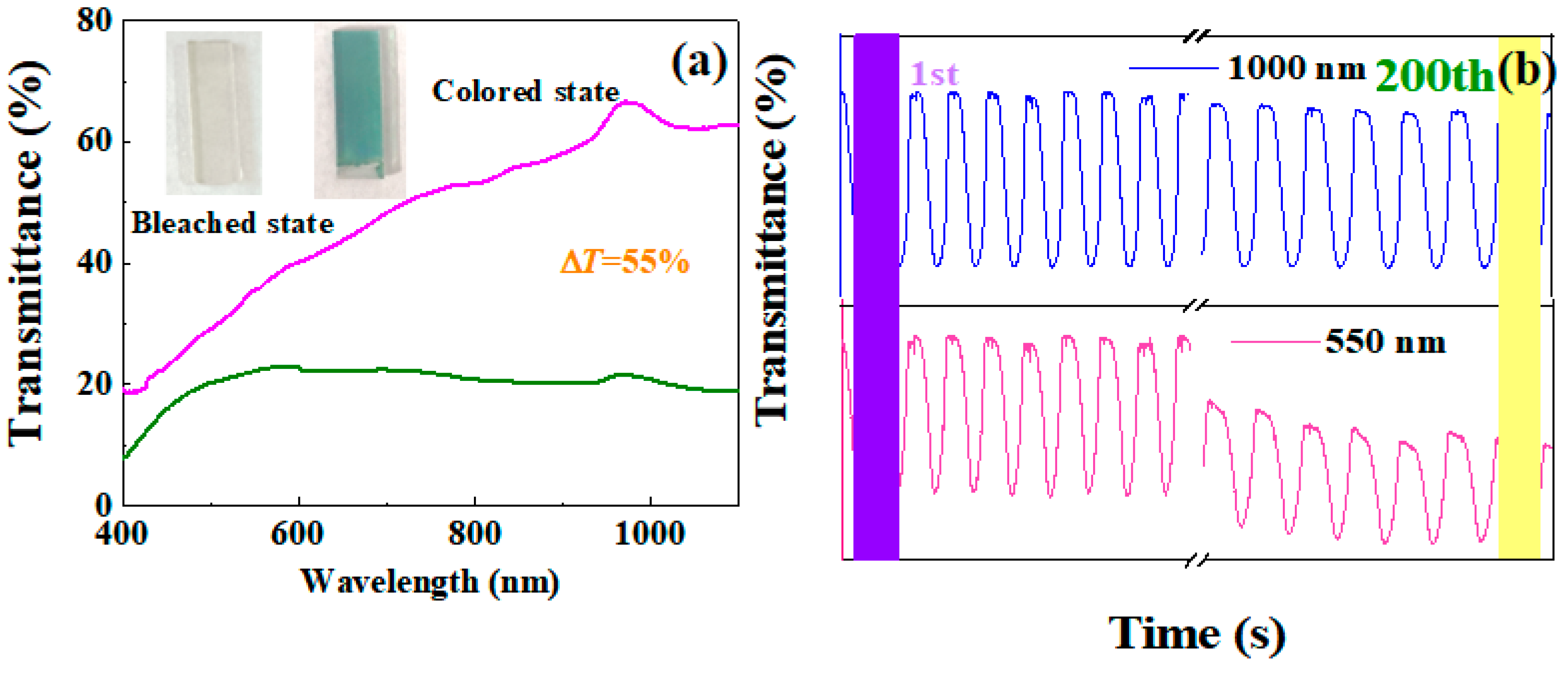
There is a significant synergistic effect between multiple metal oxides, which can effectively improve the electrochromic properties of materials. In the experiment, ZnO/FTO composites were prepared by using ZnO as the conductive layer. Titanium dioxide was deposited on the surface of TiO2/ZnO/FTO by electrodeposition, so as to obtain TiO2/ZnO/FTO composite. We tested changes in light transmittance and cycling stability. Figure 9a shows the transmittance modulation of the ZnO/TiO2/FTO thin film. The color can be reversibly switched between transparent (bleached state) and blue (colored state) over a potential range of −1.1 V to 0 V. The corresponding photo is shown in the upper left corner of Figure 9a. Light modulation exhibits wavelength-dependent changing properties. The longer the wavelength, the larger its volume, reaching a maximum (55%) at 1000 nm wavelength in the near-infrared region. In addition, the film has excellent durability, and the CV curve and photobiological modulation are not significantly reduced at different wavelengths.
After 200 cycles, the stability at 550 nm under visible light is 45%, and the high color contrast in the near-infrared region reaches 96.6% at 1000 nm, as shown in Figure 9b. Table 1 and Table 2 show a comparison of the electrochromic performance of each catalyst and the reference.

4. Conclusions

We successfully prepared porous ZnO nanosheets by a low-temperature hydrothermal method. Through photocatalytic tests, this structured material showed suitable decomposition efficiency for MO, MB and RhB, their degradation rates reaching 97.5%, 99% and 96.8%, respectively. The degradation efficiency was as high as 97.7% after mixing the three dyes. The cycling stability of this structured material is also suitable, with almost no decay in the retention of MB degradation up to 99% after 20 cycles. TiO2/ZnO composite film was prepared on FTO by the hydrothermal method and the electrodeposition method. After electrochromic performance tests, the transmittance of the composite film in visible and near-infrared bands was 55%. The cyclic stability at 550 nm band and 1000 nm band reached 45% and 96.6%, respectively. The above data indicate that ZnO nanosheets have wide application prospects in the field of photocatalysis and TiO2/ZnO/FTO composite films in the field of electrochromism. This study will contribute to the realization of multifunctional applications of materials, which will provide a new way to solve the problems of energy shortage and environmental pollution.

Author Contributions

X.L. designed this experiment and carried out the experiments. G.W. wrote the manuscript and other analyses. G.W. and H.Z. carried out the characterization tests, analyzed and wrote the results, and revised the manuscript. J.D., J.H., X.Z. and B.L. analyzed the characterization tests and wrote and revised the manuscript. J.W. and D.L. analyzed and discussed the results. All authors have read and agreed to the published version of the manuscript.

Funding

This research work was supported by the Young Scientific Research Item of Harbin University of Commerce (18XN034), the National Natural Science Foundation of China (no. 52002099) and the Foundation of State Key Laboratory of High-efficiency Utilization of Coal and Green Chemical Engineering (grant no. 2022-K74).

Institutional Review Board Statement

Not applicable.

Informed Consent Statement

Not applicable.

Data Availability Statement

The data presented in this study are available in this article.

Conflicts of Interest

The authors declare no conflict of interest.

References

  1. Sher, F.; Kawai, A.; Güleç, F.; Sadiq, H. Sustainable energy saving alternatives in small buildings. Sustain. Energy Technol. Assess. 2019, 32, 92–99. [Google Scholar] [CrossRef]
  2. Sovacool, B.K.; Griffiths, S. The cultural barriers to a low-carbon future: A review of six mobility and energy transitions across 28 countries. Renew. Sustain. Energy Rev. 2020, 119, 109569. [Google Scholar] [CrossRef]
  3. Fiory, A. Recent developments in rapid thermal processing. J. Electron. Mater. 2002, 31, 981–987. [Google Scholar] [CrossRef]
  4. Kumar, S.; Kumar, A.; Kumar, A.; Krishnan, V. Nanoscale zinc oxide based heterojunctions as visible light active photocatalysts for hydrogen energy and environmental remediation. Catal. Rev. 2020, 62, 346–405. [Google Scholar] [CrossRef]
  5. Saravanan, R.; Agarwal, S.; Gupta, V.K.; Khan, M.M.; Gracia, F.; Mosquera, E.; Narayanan, V.; Stephen, A. Line defect Ce3+ induced Ag/CeO2/ZnO nanostructure for visible-light photocatalytic activity. J. Photochem. Photobiol. A 2018, 353, 499–506. [Google Scholar] [CrossRef]
  6. Dutta, V.; Sharma, S.; Raizada, P.; Thakur, V.K.; Khan, A.A.P.; Saini, V.; Asiri, A.M.; Singh, P. An overview on WO3 based photocatalyst for environmental remediation. J. Environ. Chem. Eng. 2021, 9, 105018. [Google Scholar] [CrossRef]
  7. Ryzhikov, A.; Jońca, J.; Kahn, M.; Fajerwerg, K.; Chaudret, B.; Chapelle, A.; Ménini, P.; Shim, C.H.; Gaudon, A.; Fau, P. Organometallic synthesis of ZnO nanoparticles for gas sensing: Towards selectivity through nanoparticles morphology. J. Nanopart. Res. 2015, 17, 1–10. [Google Scholar] [CrossRef]
  8. Ngullie, R.C.; Alaswad, S.O.; Bhuvaneswari, K.; Shanmugam, P.; Pazhanivel, T.; Arunachalam, P. Synthesis and characterization of efficient ZnO/g-C3N4 nanocomposites photocatalyst for photocatalytic degradation of methylene blue. Coatings 2020, 10, 500. [Google Scholar] [CrossRef]
  9. Lu, J.; Ali, H.; Hurh, J.; Han, Y.; Batjikh, I.; Rupa, E.J.; Anandapadmanaban, G.; Park, J.K.; Yang, D.-C. The assessment of photocatalytic activity of zinc oxide nanoparticles from the roots of Codonopsis lanceolata synthesized by one-pot green synthesis method. Optik 2019, 184, 82–89. [Google Scholar] [CrossRef]
  10. Qamar, M.A.; Shahid, S.; Javed, M.; Iqbal, S.; Sher, M.; Akbar, M.B. Highly efficient g-C3N4/Cr-ZnO nanocomposites with superior photocatalytic and antibacterial activity. J. Photochem. Photobiol. A 2020, 401, 112776. [Google Scholar] [CrossRef]
  11. Ali, R.S.; Sharba, K.S.; Jabbar, A.M.; Chiad, S.S.; Abass, K.H.; Habubi, N.F. Characterization of ZnO thin film/p-Si fabricated by vacuum evaporation method for solar cell applications. NeuroQuantology 2020, 18, 26. [Google Scholar] [CrossRef]
  12. Yang, S.H.; Yang, J.-H. Enhancement on electrochromic properties of WO3-based electrode prepared with hierarchical ZnO nanobricks. Vacuum 2020, 179, 109460. [Google Scholar] [CrossRef]
  13. Wang, S.; Xu, H.; Hao, T.; Xu, M.; Xue, J.; Zhao, J.; Li, Y. 3D conifer-like WO3 branched nanowire arrays electrode for boosting electrochromic-supercapacitor performance. Appl. Surf. Sci. 2022, 577, 151889. [Google Scholar] [CrossRef]
  14. Wang, S.; Xu, H.; Hao, T.; Wang, P.; Zhang, X.; Zhang, H.; Xue, J.; Zhao, J.; Li, Y. In situ XRD and operando spectra-electrochemical investigation of tetragonal WO3-x nanowire networks for electrochromic supercapacitors. Npg Asia Mater. 2021, 13, 1–11. [Google Scholar] [CrossRef]
  15. Wang, S.; Xu, H.; Zhao, J.; Li, Y. Two-dimensional WO3 nanosheets for high-performance electrochromic supercapacitors. Inorg. Chem. Front. 2022, 9, 514–523. [Google Scholar] [CrossRef]
  16. Mahmud, R.A.; Shafawi, A.N.; Ali, K.A.; Putri, L.K.; Rosli, N.I.M.; Mohamed, A.R. Graphene nanoplatelets with low defect density as a synergetic adsorbent and electron sink for ZnO in the photocatalytic degradation of Methylene Blue under UV–vis irradiation. Mater. Res. Bull. 2020, 128, 110876. [Google Scholar] [CrossRef]
  17. Qu, Y.; Huang, R.; Qi, W.; Shi, M.; Su, R.; He, Z. Controllable synthesis of ZnO nanoflowers with structure-dependent photocatalytic activity. Catal. Today. 2020, 355, 397–407. [Google Scholar] [CrossRef]
  18. Chen, D.; Cheng, Y.; Zhou, N.; Chen, P.; Wang, Y.; Li, K.; Huo, S.; Cheng, P.; Peng, P.; Zhang, R.; et al. Photocatalytic degradation of organic pollutants using TiO2-based photocatalysts: A review. J. Clean. Prod. 2020, 268, 121725. [Google Scholar] [CrossRef]
  19. Li, S.; Chen, X.; Cheng, Z.; Luo, S.; Nguyen, T.T.; Guo, M.; Gao, X. Promoting effect of cellulose-based carbon dots at different concentrations on multifunctional photocatalytic degradation of dyes by ZnO. Opt. Mater. 2021, 121, 111591. [Google Scholar] [CrossRef]
  20. Tahir, M.; Tasleem, S.; Tahir, B. Recent development in band engineering of binary semiconductor materials for solar driven photocatalytic hydrogen production. Int. J. Hydrogen Energy 2020, 45, 15985–16038. [Google Scholar] [CrossRef]
  21. Shaikh, S.F.; Mane, R.S.; Min, B.K.; Hwang, Y.J.; Joo, O.S. D-sorbitol-induced phase control of TiO2 nanoparticles and its application for dye-sensitized solar cells. Sci. Rep. 2016, 6, 20103. [Google Scholar] [CrossRef]
  22. Al-Enizi, A.M.; Shaikh, S.F.; Tamboli, A.M.; Marium, A.; Ijaz, M.F.; Ubaidullah, M.; Moydeen Abdulhameed, M.; Ekar, S.U. Hybrid ZnO Flowers-Rods Nanostructure for Improved Photodetection Compared to Standalone Flowers and Rods. Coatings 2021, 11, 1464. [Google Scholar] [CrossRef]
  23. Sharma, S.; Dutta, V.; Raizada, P.; Thakur, V.K.; Saini, A.K.; Mittal, D.; Nguyen, V.-H.; Ahamad, T.; Nguyen, C.C.; Kim, S.Y.; et al. Synergistic photocatalytic dye mitigation and bacterial disinfection using Carbon quantum dots decorated dual Z-scheme Manganese Indium Sulfide/Cuprous Oxide/Silver oxide heterojunction. Mater. Lett. 2022, 313, 131716. [Google Scholar] [CrossRef]
  24. Ahamad, T.; Naushad, M.; Ruksana; Alhabarah, A.N.; Alshehri, S.M. N/S doped highly porous magnetic carbon aerogel derived from sugarcane bagasse cellulose for the removal of bisphenolA. Int. J. Biol. Macromol. 2019, 132, 1031–1038. [Google Scholar] [CrossRef]
  25. Reddy, I.N.; Reddy, C.V.; Shim, J.; Akkinepally, B.; Cho, M.; Yoo, K.; Kim, D. Excellent visible-light driven photocatalyst of (Al, Ni) co-doped ZnO structures for organic dye degradation. Catal. Today 2020, 340, 277–285. [Google Scholar] [CrossRef]
  26. Wang, Y.N.; Li, J. Cerium modified rod-like ZnO graphene complex and its photocatalytic properties under visible-light irradiation. Opt. Mater. 2020, 108, 110203. [Google Scholar] [CrossRef]
  27. Karthikeyan, C.; Arunachalam, P.; Ramachandran, K.; Al-Mayouf, A.M.; Karuppuchamy, S. Recent advances in semiconductor metal oxides with enhanced methods for solar photocatalytic applications. J. Alloy. Compd. 2020, 828, 154281. [Google Scholar] [CrossRef]
  28. Kegel, J.; Povey, I.M.; Pemble, M.E. Zinc oxide for solar water splitting: A brief review of the material’s challenges and associated opportunities. Nano Energy 2018, 54, 409–428. [Google Scholar] [CrossRef]
  29. Mandal, S.K.; Paul, S.; Datta, S.; Jana, D. Nitrogenated CQD decorated ZnO nanorods towards rapid photodegradation of rhodamine B: A combined experimental and theoretical approach. Appl. Surf. Sci. 2021, 563, 150315. [Google Scholar] [CrossRef]
  30. Shah, A.A.; Chandio, A.D.; Sheikh, A.A. Boron doped ZnO nanostructures for photo degradation of methylene blue, methyl orange and rhodamine B. J. Nanosci. Nanotechno. 2021, 21, 2483–2494. [Google Scholar] [CrossRef]
  31. Sultana, K.A.; Islam, M.T.; Silva, J.A.; Turley, R.S.; Hernandez-Viezcas, J.A.; Gardea-Torresdey, J.L.; Noveron, J.C. Sustainable synthesis of zinc oxide nanoparticles for photocatalytic degradation of organic pollutant and generation of hydroxyl radical. J. Mol. Liq. 2020, 307, 112931. [Google Scholar] [CrossRef]
  32. Khalafi, T.; Buazar, F.; Ghanemi, K. Phycosynthesis and enhanced photocatalytic activity of zinc oxide nanoparticles toward organosulfur pollutants. Sci. Rep.-UK 2019, 9, 1–10. [Google Scholar] [CrossRef] [PubMed]
  33. Singh, K.; Singh, J.; Rawat, M. Green synthesis of zinc oxide nanoparticles using Punica Granatum leaf extract and its application towards photocatalytic degradation of Coomassie brilliant blue R-250 dye. SN Appl. Sci. 2019, 1, 1–8. [Google Scholar] [CrossRef] [Green Version]
  34. Kumar, M.; Abebe, B.; Nagaswarupa, H.; Murthy, H.; Ravikumar, C.; Sabir, F.K. Enhanced photocatalytic and electrochemical performance of TiO2-Fe2O3 nanocomposite: Its applications in dye decolorization and as supercapacitors. Sci. Rep. 2020, 10, 1–15. [Google Scholar] [CrossRef] [Green Version]
  35. Yadav, A.; Hunge, Y.; Kulkarni, S. Synthesis of multifunctional FeCo2O4 electrode using ultrasonic treatment for photocatalysis and energy storage applications. Ultrason. Sonochem. 2019, 58, 104663. [Google Scholar] [CrossRef]
  36. Bantawal, H.; Sethi, M.; Shenoy, U.S.; Bhat, D.K. Porous graphene wrapped SrTiO3 nanocomposite: Sr–C bond as an effective coadjutant for high performance photocatalytic degradation of methylene blue. ACS Appl. Nano Mater. 2019, 2, 6629–6636. [Google Scholar] [CrossRef]
  37. Sharma, G.; Kumar, A.; Sharma, S.; Naushad, M.; Dhiman, P.; Vo, D.-V.N.; Stadler, F.J. Fe3O4/ZnO/Si3N4 nanocomposite based photocatalyst for the degradation of dyes from aqueous solution. Mater. Lett. 2020, 278, 128359. [Google Scholar] [CrossRef]
  38. Ma, H.; Hao, B.; Song, W.; Guo, J.; Li, M.; Zhang, L. A High-Efficiency TiO2/ZnO Nano-Film with Surface Oxygen Vacancies for Dye Degradation. Materials 2021, 14, 3299. [Google Scholar] [CrossRef]
  39. Ju, X.; Yang, F.; Zhu, X.; Jia, X. Zinc ion intercalation/deintercalation of metal organic framework-derived nanostructured NiO@ C for low-transmittance and high-performance electrochromism. ACS Sustain. Chem. Eng. 2020, 8, 12222–12229. [Google Scholar] [CrossRef]
  40. Wang, J.; Liu, X.A.; Zhang, D.; Tong, Z.; Ji, H.; Qu, H.Y. Zn2+ intercalation/de-intercalation-based aqueous electrochromic titanium dioxide electrode with Zn-ion storage. Ionics 2021, 27, 4429–4437. [Google Scholar] [CrossRef]
  41. Wang, L.; Liu, Y.; Han, G.; Zhao, H. Controllable synthesis of hexagonal WO3 nanorod-cluster films with high electrochromic performance in NIR range. J. Alloy. Compd. 2022, 890, 161833. [Google Scholar] [CrossRef]
  42. Ling, H.; Yeo, L.P.; Wang, Z.; Li, X.; Mandler, D.; Magdassi, S.; Tok, A.I.Y. TiO2–WO3 core–shell inverse opal structure with enhanced electrochromic performance in NIR region. J. Mater. Chem. C 2018, 6, 8488–8494. [Google Scholar] [CrossRef]
  43. Zhang, B.; Xu, C.; Xu, G.; Tan, S.; Zhang, J. Amorphous titanium dioxide film with improved electrochromism in near-infrared region. Opt. Mater. 2019, 89, 191–196. [Google Scholar] [CrossRef]
Figure 1. Schematic diagram of the as-prepared porous ZnO nanosheets.
Coatings 12 00695 g001
Figure 2. (a) Low-magnification SEM images of ZnO nanosheets without hydrothermal treatment. (b) High-magnification SEM images of ZnO nanosheets without hydrothermal treatment. (c) Low-magnification SEM images of ZnO nanosheets after hydrothermal treatment. (d) High-magnification SEM images of ZnO nanosheets after hydrothermal treatment. (e) SEM mapping of the porous ZnO nanosheets.
Coatings 12 00695 g002
Figure 3. (a) Low-magnification TEM images of the porous ZnO nanosheets. (b) High-resolution TEM images of the porous ZnO nanosheets. (c) Energy spectrum analysis of the porous ZnO nanosheets. (d) XRD patterns of the porous ZnO nanosheets. (e) Nitrogen adsorption/desorption curve of the porous ZnO nanosheets. (f) Pore size distribution curve of the porous ZnO nanosheets.
Coatings 12 00695 g003
Figure 4. Adsorption kinetic curves of ZnO on MO, MB and RhB dyes.
Coatings 12 00695 g004
Figure 5. Photocatalytic degradation curves of different dyes: (a) MO; (c) MB; (e) RhB. Images of the dyes at different degradation times: (b) MO; (d) MB; (f) RhB.
Coatings 12 00695 g005
Figure 6. Photocatalytic reaction mechanism diagram.
Coatings 12 00695 g006
Figure 7. (a) Degradation rate value curves of different dyes at the same time. (b) Photocatalytic degradation curves of the mixed dyes.
Coatings 12 00695 g007
Figure 8. Cycling properties of MB for 20 cycles.
Coatings 12 00695 g008
Figure 9. Electrochromic properties of TiO2/ZnO/FTO thin films. (a) Visible–near-infrared transmittance spectra of the bleached and colored TiO2/ZnO/FTO films, illustrated by corresponding photographs of 1 × 4 cm2 TiO2/ZnO/FTO electrodes; (b) 200 cycles of TiO2/ZnO/FTO films at 550 nm and 1000 nm, respectively.
Coatings 12 00695 g009
Table 1. Comparison of catalytic performance.
MaterialDyeDegradation
Efficiency
Cycle StabilityRef
ZnO NPSDBT95% (190 min)93% (5 cycles)[32]
ZnO NPSR-25093% (180 min) [33]
TiO2 -Fe2O3Titan Yellow92.98% (60 min) [34]
FeCo2O4Crystal Violet94.19% (160 min)92.06% (5 cycles)[35]
SrTiO3MB92% (120 min) [36]
Fe3O4/ZnO/Si3N4MO96% (80 min)90% (6 cycles)[37]
Fe3O4/ZnO/Si3N4Sunset Yellow90% (80 min)90% (6 cycles)[37]
ZnO/TiO2RhB90.8% (120 min) [38]
ZnOMB99% (40 min)99% (20 cycles)this paper
ZnOMO97.7% (90 min) this paper
TiO2/ZnORhB96.8% (120 min) this paper
Table 2. Comparison of electrochromic performance.
MaterialWavelength (nm)TransmittanceRetentionReferences
NiO@C120035% [39]
TiO298045%93% (100 cycles)[40]
NiO65041.08%86% (100 cycles)[13]
WO3160046%96% (1000 cycles)[41]
TiO2-WO3120055%Over 90% (1200 cycles)[42]
TiO290028% [43]
TiO2/ZnO/FTO100055%96.6% (200 cycles)this paper
Publisher’s Note: MDPI stays neutral with regard to jurisdictional claims in published maps and institutional affiliations.