Article

Effect of La2O3 on Microstructure and Properties of Laser Cladding SMA Coating on AISI 304 Stainless Steel

1
School of Mechanical Engineering, Dalian Jiaotong University, Dalian 116028, China
2
College of Materials and Metallurgy, Guizhou University, Guiyang 550025, China
*
Author to whom correspondence should be addressed.
Coatings 2022, 12(7), 1004; https://doi.org/10.3390/coatings12071004
Submission received: 24 June 2022 / Revised: 6 July 2022 / Accepted: 15 July 2022 / Published: 17 July 2022
(This article belongs to the Special Issue Recent Advances in Functional Surfaces and Interfaces)

Abstract

:
Known as having a stress self-accommodation characteristic, the laser cladding shape memory alloy (SMA) coatings have been widely used in material failure repair. Nevertheless, their further development is greatly limited by their low microhardness (250 HV0.2) and corrosion resistance. Benefiting from the capability of refined grain and adjusted microstructure, rare earth oxides play a key role in improving the properties of materials. Herein, to improve the microhardness and anti-corrosion of laser cladding SMA coatings, different amounts of La2O3 were doped in SMA coating. The influence of the different La2O3 doping amounts on the phases, grain size and microhardness was studied. The anti-corrosion of the SMA/La2O3 composite coating was explored in 3.5 wt.% sodium chloride solution. Results showed that the grain of the SMA/La2O3 composite coating is significantly refined. When doping with 0.9 wt.%, the refinement rate reaches 19%. Furthermore, based on the Hall–Petch effect, the microhardness of the SMA/La2O3 composite coating is increased to 450 HV0.2. At the same time, the anti-corrosion of the composite coating is enhanced due to the smaller grain size and fewer defects.

1. Introduction

As the conditions of service become more stringent, materials are put forward for higher demands and the problem of material failure becomes more and more severe [1,2]. Based on the advantages of the small heat-affected zone and metallurgical bonding [3,4], laser cladding technology is widely applied in material failure repair [5]. Nevertheless, the residual stress caused by the extremely fast cooling rate will affect the service life. In order to better apply laser cladding technology to material failure repairing, how to further reduce the residual stress has become an urgent problem to be solved [6].
Over the past few decades, extensive studies have been carried out in the field of residual stress release due to its crucial role in practical application [7,8]. Heat treatment was used to reduce the residual stresses by Park [9], and the residual stress was reduced by 50% after a 700 °C treatment. Roehling [10] developed an in situ annealing method to weaken residual stresses in a coating fabricated by LPBF (laser powder bed fusion). The result shows that a residual stress decrease of 90% was achieved in the coating. However, these methods mentioned above have a complex process and high production costs.
Recently, Fe-Mn-Si shape memory alloy (SMA) has attracted more and more attention owing to its stress self-accommodation characteristic. Xu et al. [11] fabricated Fe-Mn-Si-Ni-Cr SMA coating using laser cladding technology, which greatly weakens the residual stress of the coating. Ferretto et al. [12] prepared Fe17Mn5Si10Cr4Ni SMA parts by LPBF for the first time, which further promotes the development of SMA. However, the anti-corrosion and lower microhardness (only 250 HV0.2) are two key factors that limit its industrial application. To strengthen the performance of SMA coating, PZT, Ti, WC and Nb were used for modification. The corrosion resistance and microhardness were enhanced significantly. However, there is still a certain gap from the practical application [13,14].
Benefiting from their good chemical and physical properties as well as grain refinement, rare earth elements, honored as industrial vitamins, play a vital role in improving the microhardness, wear resistance and anti-corrosion of materials [15,16]. Rare earth elements can purify molten steel, improve inclusions and refine grains, which is an effective method for adjusting the microstructure and enhancing the mechanical properties of steel. Du et al. [17] prepared Y2O3-doped, WC-reinforced coating via laser cladding technology. The result showed that the addition of Y2O3 promoted the metallurgical bonding between the coating and the substrate, and also improved the weldability and laser absorption rate of Invar alloys. By adding different amounts of La2O3, Y2O3 and CeO2, the grains of Ni60 coating were significantly refined and the microhardness was significantly improved [18]. Liu et al. [19] doped different amounts of CeO2 in TiC/Ti2Ni coating. The result showed that the microhardness and wear resistance of the composite coating was greatly enhanced. Therefore, rare earth element alloying is an effective method to improve the properties of materials.
To further strengthen the properties of Fe-Mn-Si shape memory alloy composite coating, A FeMnSiCrNiNb/(La2O3)x (x = 0.3, 0.6, 0.9, 1.2 wt.%) composite coating was prepared via laser cladding technology. The XRD, Vickers hardness tester, the MFT-5000 Tribometer and electrochemical workstation were applied to explore the phases, microhardness and anti-corrosion of coatings.

2. Materials and Methods

2.1. Experimental Materials and Design

We used AISI 304 stainless steel (SS) as the matrix. The oxide was removed before laser cladding. The composition of AISI 304 SS and experimental powder (50–100 μm) were shown in Table 1. The experimental powder was ball-milled (QM-3SP2) for 2 h and then dried. The fiber laser system was used for laser cladding experiment (YLS6000; IPG Photonics Corporation, KUKA, Germany). The parameters: the pre-sintered powder thickness was 1.5 mm, the laser power (P) was 2000 W at a scanning rate of 6 mm/s. An experimental schematic diagram and powder preparation flow chart are shown in Figure 1.

2.2. Sample Characterization

The coatings were cut into cubes by wire electrical discharge machining (7 mm × 7 mm × 7 mm) and polished with a polishing compound (Shanghai Yunbo Testing Technology, Shanghai, China). X-ray diffraction (XRD, DX-2700B, HAOYUAN Instrument, Dandong, China) was applied to investigate the phases, and the 2θ varied from 10° to 90°. The microhardness and wear resistance of the coating were tested using the HV-50 Vickers microhardness tester (AICEYI Opto-electronic Technology, HongKong, China) and the MFT-5000 Tribometer (the reciprocating distance is 4 mm, the test time is 15 min and the load is 10 N). Scanning electron microscopy (SEM, COXEM, EM30, Daejeon, Korea) was used to analyze the surface microstructure. Elemental analysis of the samples was performed using Energy-dispersive X-ray spectroscopy (EDS, Oxford instruments, Oxford, UK).
The polarization plots were measured by the three-electrode system of a electrochemical workstation (CHI660D; CH Company, Ltd. Shanghai, China) in 3.5 wt.% sodium chloride solution (macklin, AR, Shanghai, China) at 25 °C. The Pt electrode and saturated calomel electrode were used as a counter electrode (the area of Pt is 1 cm2) and reference electrode, respectively. Voltage ranged from −2 V to 2 V, scan rate was 0.01 V/s and the sample exposure area was 0.49 cm2. The electrochemical impedance spectroscopy (EIS) was used to test the impedance of the coating. The frequency ranged from 100 to 106 HZ and the amplitude was 0.005 V [20]. ZView software (version: 3.1) was used to simulate the equivalent circuit.

3. Results and Discussion

3.1. Phases Analysis

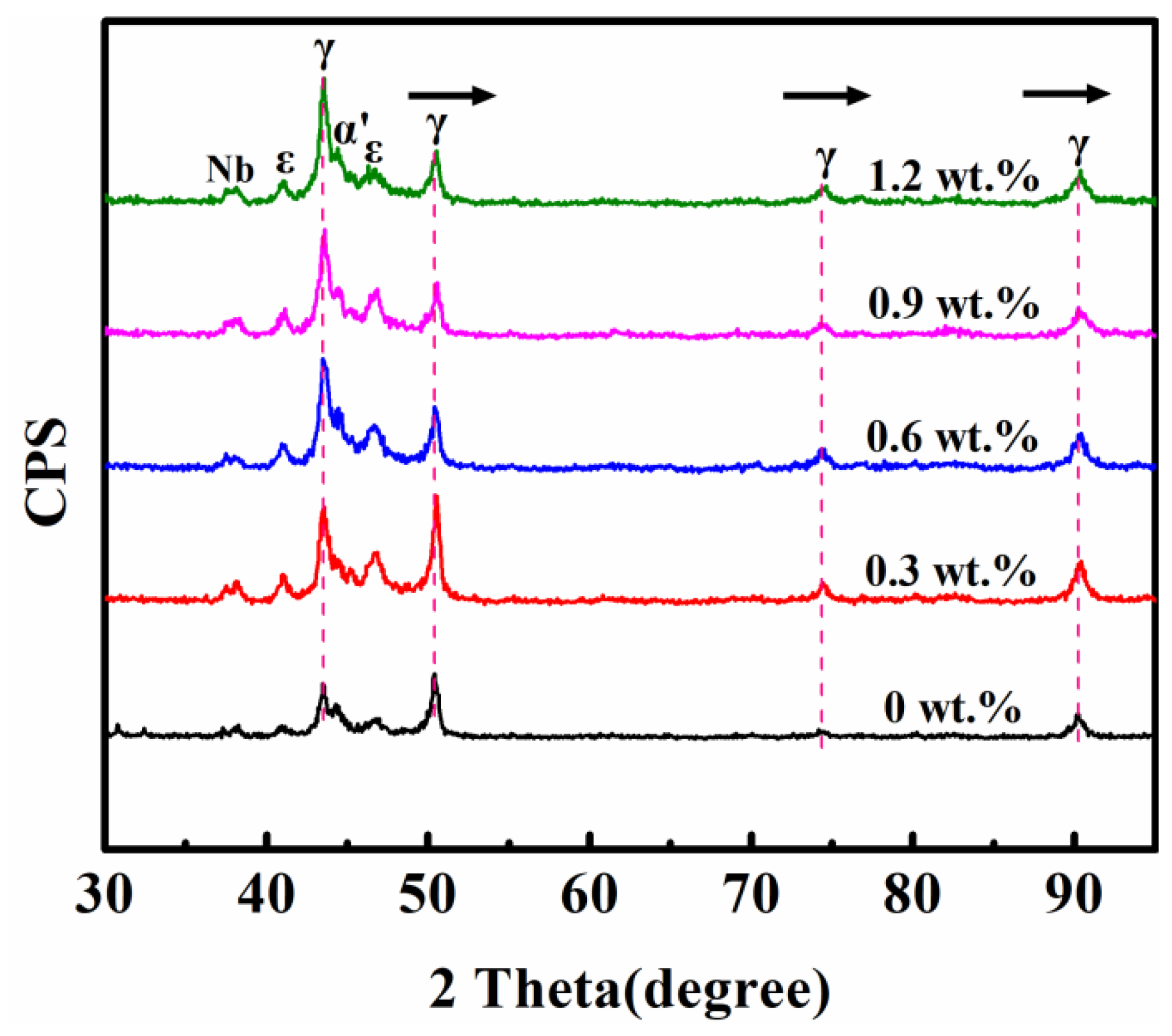
The XRD patterns of La2O3 doped with different amounts are shown in Figure 2. There is no obvious difference in the XRD patterns, all of which are composed of an Nb phase, thermoelastic ε-martensite, non-thermoelastic α’-martensite and γ-austenite phases. The presence of thermoelastic ε-martensite proves that γ-austenite transformation occurs in the SMA coating, which is the characteristic of SMAs [21,22]. Furthermore, thermoelastic ε-martensite is also key to the shape memory effect. Meanwhile, the γ-austenites of the composite coatings are all shifted to high angles, which indicates that the interplanar spacing d decreases based on the Bragg equation (2dsinθ = nλ).
In addition, Figure 3 exhibits a lot of white area on the surface (white circle), and EDS analysis indicates that the Nb phase is precipitated in this area, which is consistent with the XRD pattern [23].

3.2. Microstructure

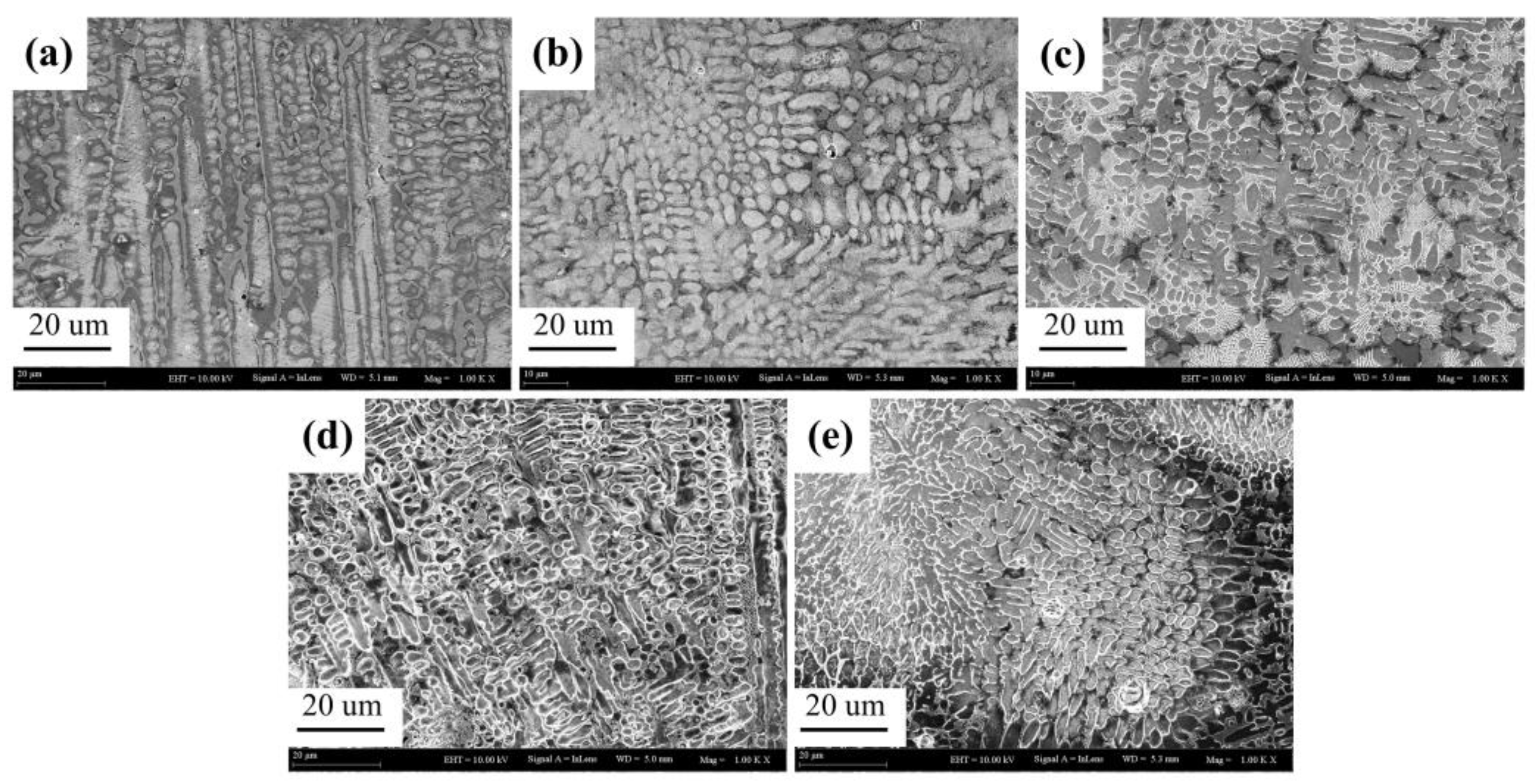
Figure 4a shows that a large number of columnar crystals were observed in SMA coatings. After doping with La2O3, the grains of the coating were significantly refined, mainly forming cellular crystals, as shown in Figure 4b,e. This is because the rare earth oxides act as heterogeneous nucleation sites, increase the probability of heterogeneous nucleation, and refine grains [24,25]. Figure 5 shows the average grain size of the coatings. The average grain size of the SMA coating reached 3.72 μm, and the grain was gradually refined with La2O3 doping. Especially when doping La2O3 with 0.9 wt.%, the average grain size decreased to 3.03 μm, and the refinement rate reached 19%. However, when doped 1.2 wt.%, the grain size increased to 3.12 μm. This is attributed to the segregation of excess La2O3 at the grain boundaries, weakening the refining effect and increasing the average grain size [26,27].
In addition, as shown in Figure 6 [28,29], plenty of eutectic microstructures containing Fe, Si, Mn and Nb elements were also formed on the grain boundary of the SMA/La2O3 composite coating, as shown in Table 2.

3.3. Microhardness and Wear Resistance

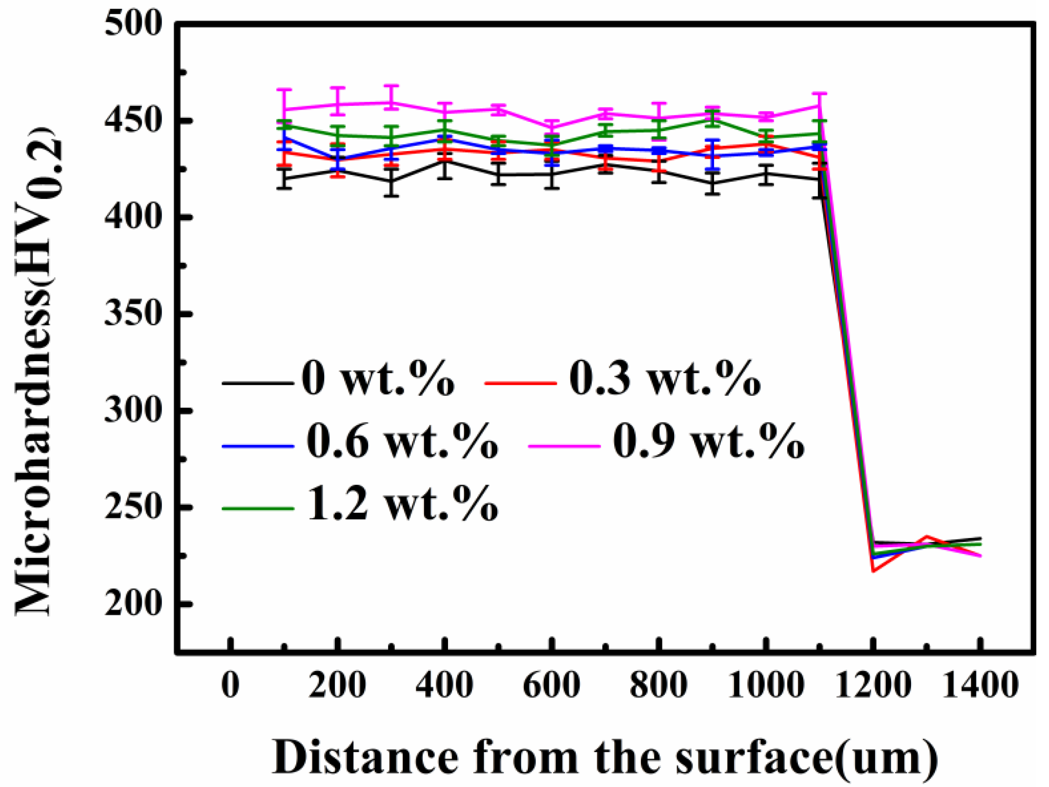
The microhardness changes in the cross-section are shown in Figure 7. After doping with La2O3, the microhardness of the SMA/La2O3 composite coating was enhanced. When doped with 0.9 wt.%, the microhardness reached 450 HV0.2. The grain size of the composite coating was obviously refined, and the grain distribution changed from the columnar crystal to the cellular crystal, as shown in Figure 4. Based on the Hall–Petch formula [30,31], the smaller grain size shows the higher grain interface in the unit volume. The grain boundaries possess higher dislocation density due to the atoms being arranged randomly, resulting in the dislocation tangling and the resistance of movement increasing significantly. Thus, the microhardness of the composite coating is strengthened.
σ d = σ 0 + k d 1 2
where σ0 (MPa) is internal friction stress; k is a material constant related to the stress concentration required to activate slip dislocations; d (mm) is the average grain size of the material.
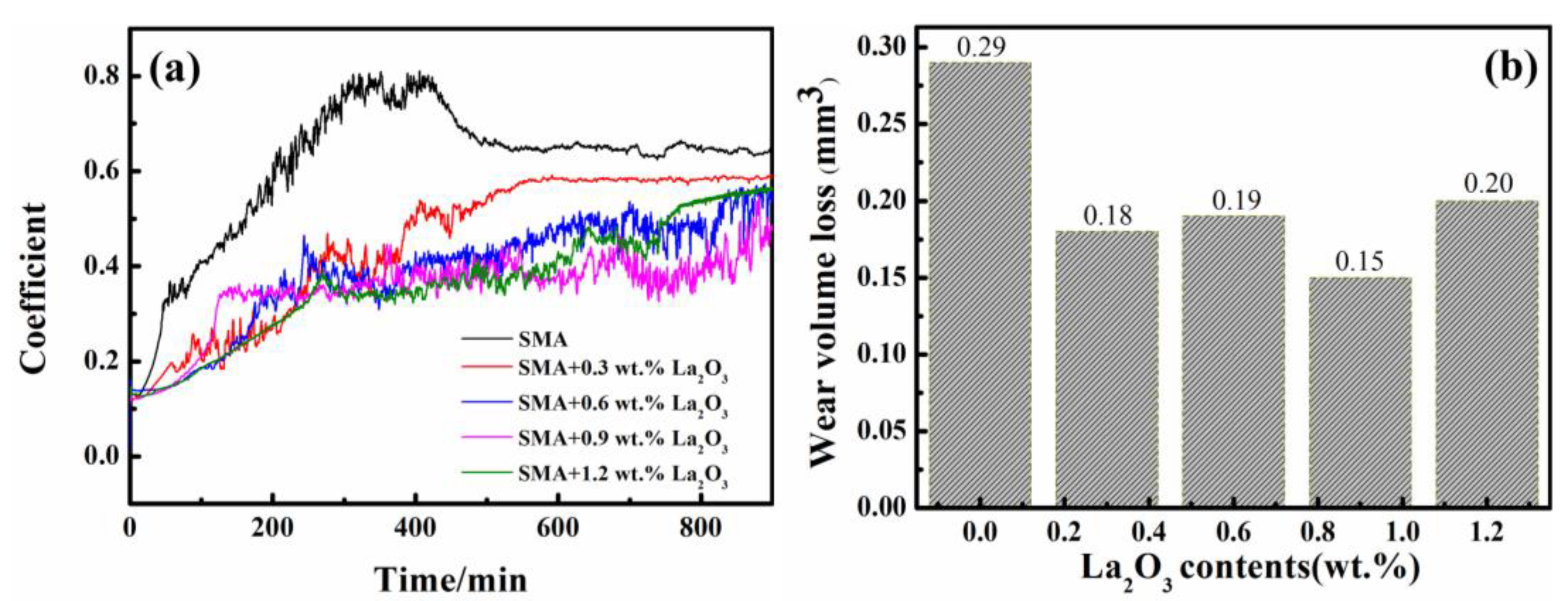
The friction coefficient can be used to estimate the anti-wear. The smaller the friction coefficient is, the better the wear resistance of the coating is. Figure 8a shows that the friction coefficient decreased significantly after doping La2O3. When doping with 0.9 wt.%, the friction coefficient was the smallest, at only about 0.3. With continued doping, the friction coefficient increased slightly. The friction coefficient and microhardness are consistent with Archard’s tribology theory [32]. Wear resistance is further analyzed by wear volume loss. Figure 8b shows that the wear volume loss is only 0.15 mm3 at 0.9 wt.%, much lower than that of SMA coating. It is worth noting that the microhardness and friction coefficient of the coating are slightly improved when the doping is 1.2 wt.%. Apparently, Figure 5 shows that the average grain size of the SMA/(La2O3)1.2 wt.% composite coating reached 3.12 μm, and some columnar crystals appeared (the circle of Figure 6d). According to the Hall–Petch formula, the microhardness and friction coefficient are slightly reduced [33].
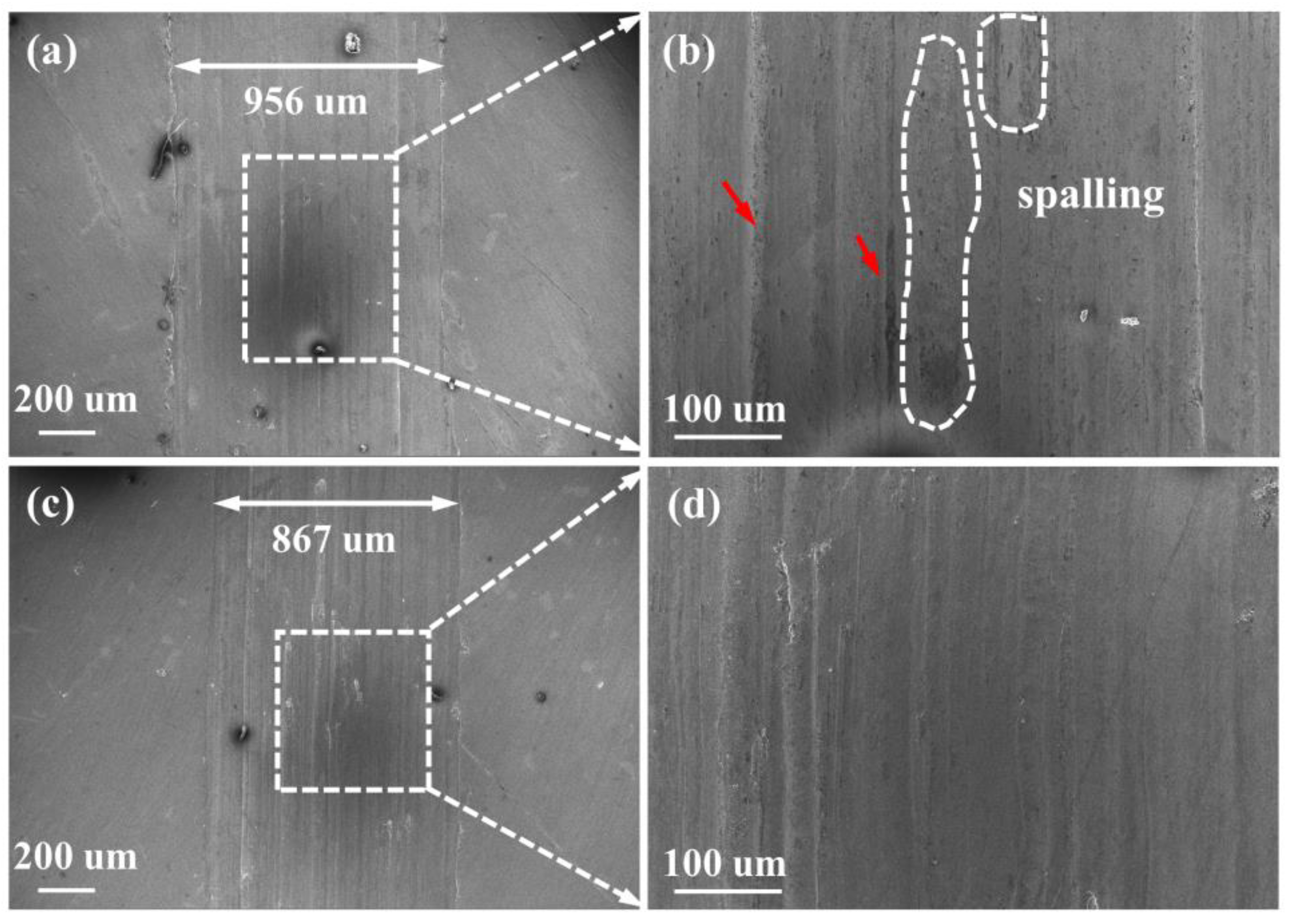
As shown in Figure 9. the wear width of SMA coating reaches 956 μm, while the width of SMA/(La2O3)0.9 wt.% composite coating is only 867 μm, indicating that the composite coating has better wear resistance. Furthermore, plenty of furrow marks, which are caused by the falling off of particles on the surface and continued wear of the surface, were observed in both SMA coatings, which is called abrasive wear. However, the wear scars’ depth of the SMA coating is significantly deeper than that of the SMA/La2O3 composite coating (the arrow of Figure 9b) owing to the lower microhardness. Moreover, a large area of spalling on the surface was observed in Figure 9b, which is typical of adhesion wear, which is a more serious wear form than abrasive wear. In contrast, the wear marks of the SMA/La2O3 composite coating are smoother and flatter. Although there is some spalling, the area is smaller compared with the SMA coating [34,35].

3.4. Corrosion Resistance

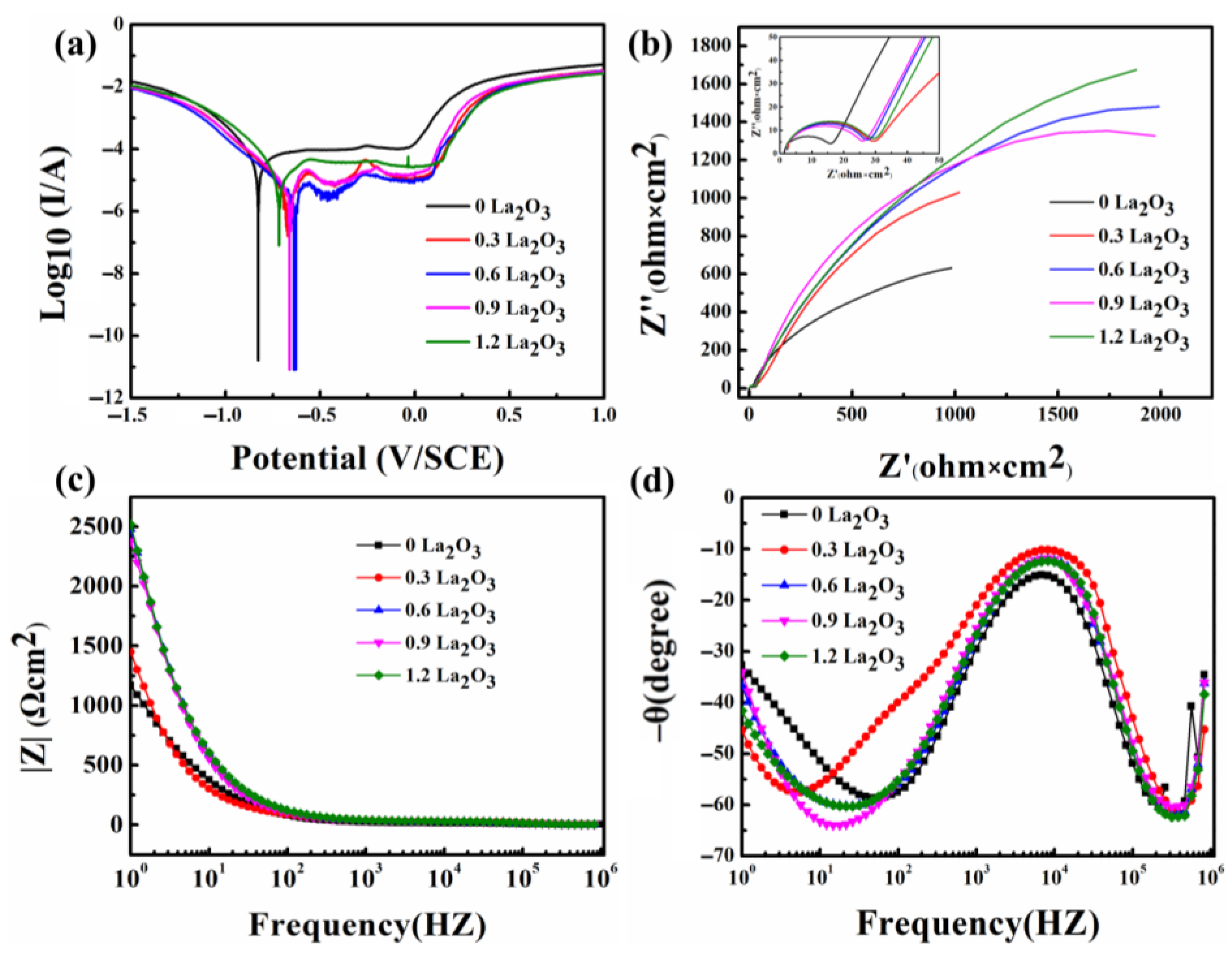
The electrochemical impedance spectroscopy (EIS) and polarization curve were tested to further characterize the anti-corrosion of the coatings [36]. In general, the smaller the self-corrosion current (Icorr) is, the smaller the corrosion rate is, and the greater the self-corrosion voltage (Ecorr) is, the greater the anti-corrosion of the coating is [37,38].
Figure 10a shows the polarization curves of samples doped with different amounts of La2O3. After doping La2O3, the Ecorr of the composite coatings was significantly improved. When doping with 0.6 wt.%, the Ecorr of the coating reached −0.64 V, while the Icorr was the smallest, at only 4.556 × 10⁻⁶. With further doping, Ecorr showed a reducing trend, as shown in Table 3. Moreover, the corrosion rates (gram/hr and mil/year) of composite coatings were obviously lower than that of the SMA coating. In particular, when doped with 0.6 wt.%, the corrosion rate of the composite coating decreased by an order of magnitude (3.173 × 10⁻⁶/3.296 × 10−5 and 29.52/2.842) compared to the SMA coating [39].
The Nyquist plots of the coatings reflect the resistance of the coatings. Z′ and Z″ are the real and virtual parts of the impedance, respectively. The |Z| total impedance modulus is shown as Equation (2) [40]. A larger radius shows greater anti-corrosion [41,42]. Obviously, the radius of the SMA/La2O3 composite coating is higher than that of the SMA coating. When doped with 0.6 wt.%, the radius of coating resistance reaches the maximum, as shown in Figure 10b. There was no obvious change in radius as doping continued.
| Z | = Z 2 + Z 2
Figure 10c shows the bode plot of the coatings. |Z| can be applied to evaluate the anti-corrosion of the coatings in low frequency. When the doping amount exceeds 0.6 wt.%, the |Z| of the composite coating is higher than that of the SMA coating from high frequency to low frequency, indicating that doping La2O3 is an effective method to improve corrosion resistance. Figure 10d shows the frequency–phase plot. Obviously, there is only one wave peak, indicating that coating has only one time constant.
It is generally believed [9,10] that the grain refinement by conventional methods will increase the surface defects in the alloy and reduce the anti-corrosion. On the contrary, the addition of rare earth oxides (La2O3) in the alloy can not only refine the grain but also generate inclusions with impurity elements S and Al, which can purify the microstructure and improve the anti-corrosion. The protection rate of the composite coating was determined according to Equation (3) [43].
η = i c o r r 0 i c o r r i c o r r 0
where icorr and i0corr represent the Icorr of the composite coating and original coating, respectively. According to Equation (3), when doping with 0.6 wt.%, the coating protection rate increased by 20%.
In order to more accurately describe the anti-corrosion, the equivalent circuit was used to simulate EIS parameters. As shown in Figure 11, the EIS data are shown in Table 4. Here, Rct, Rs, Rf and CPE represent the film resistance charge transfer resistance, solution resistance, coating resistance and constant phase element, respectively. The CPE is applied to compensate the non-uniformity of the system instead of capacitors. The CPE is defined using the equation of ZCPE = [Y(jω)n]1, where n represents the dimensionless index, ω represents the frequency and Y represents the CPE constant. If n = 1, the CPE is the equivalent capacitor; if n = 0, the CPE is the equivalent resistance [44].
The capacitance (C) of the coating is calculated by resistance R and CPE (Q), respectively [45]:
C = ( Q R ) 1 n R
Rs of all coatings are lower 2 Ω, which will not affect the results. Benefiting from the grain refinement, the Cdl of the composite coating decreased by 1–2 orders of magnitude, and the Rct increased by 3 to 6 times compared with SMA coating. In particular, the SMA/(La2O3)0.9 wt.% composite coating processes the minimum Cdl and maximum n value, proving that the corrosion of the composite coating was more difficult. When doping with 1.2 wt.%, the Cdl gradually increased and n decreased. This is consistent with the previous results.
In summary, the anti-corrosion of the SMA/La2O3 composite coating is higher than that of the SMA coating.

4. Conclusions

In this paper, an SMA/La2O3 composite coating was prepared on AISI 304 SS using laser cladding technology so as to improve the microhardness and anti-corrosion of an SMA coating. The result shows that the phases of all coatings are composed of an Nb phase, thermoelastic ε-martensite, non-thermoelastic α’-martensite and γ-austenite phases. The presence of thermoelastic ε-martensite proves that γ-austenite transformation occurs in the SMA coatings, which is the characteristic of SMAs, and it is also the key to the shape memory effect. The advantage of using rare earth oxide as a heterogeneous nucleation site can increase the probability of heterogeneous nucleation and refine the grain. Based on the Hall–Petch formula, The smaller the grain size, the higher the microhardness. When doping with 0.9 wt.%, the average grain size of the composite coating decreases to only 3.03 μm, and the refinement rate reaches 19%, which greatly improves the microhardness and anti-wear of the coating. Due to the low microhardness of the SMA coating, the surface has a large area of peeling, and the wear pit is larger and deeper after friction testing, corresponding to abrasive wear and adhesive wear. On the contrary, the surface of the composite coating has only abrasive wear, and the wear scars are more shallow.
The Ecorr and Icorr of the composite coating are significantly improved; this is attributed to the addition of La2O3 in the alloy which can not only refine the grain but also generate inclusions with impurity elements S and Al, which can purify the microstructure and improve the anti-corrosion. Compared with the SMA coating, the Cdl of the composite coating decreases by 1–2 orders of magnitude and the Rct increases by 3–6 times, indicating that the corrosion of the coating is more difficult.

Author Contributions

Methodology, L.L. and Y.Q.; Validation, Y.Q.; Formal analysis, L.L.; Writing—original draft preparation, L.L.; Writing—review and editing, P.X.; Supervision, P.X.; Funding acquisition, P.X. All authors have read and agreed to the published version of the manuscript.

Funding

This study was funded by the Guizhou Provincial Science and Technology Foundation (QKHJC ZK [2021] general 241), the Natural Science Research Project of Guizhou Provincial Education Department (QJH KY Z [2021]098), the Guizhou Provincial Science and Technology Innovative Talent Team (QKHPTRC [2020]5022) and Fostering Projects of Guizhou University ([2020]66).

Institutional Review Board Statement

Not applicable.

Informed Consent Statement

Not applicable.

Data Availability Statement

Not applicable.

Conflicts of Interest

The authors declare no conflict of interest.

References

  1. Pathania, A.; Kumar, S.A.; Nagesha, B.K.; Barad, S.; Suresh, T.N. Reclamation of titanium alloy based aerospace parts using laser based metal deposition methodology. Mater. Today 2021, 45, 4886–4892. [Google Scholar] [CrossRef]
  2. Avery, D.Z.; Cleek, C.E.; Phillips, B.J.; Rekha, M.Y.; Kinser, R.P.; Rao, H.M.; Brewer, L.N.; Allison, P.G.; Jordon, J.B. Evaluation of Microstructure and Mechanical Properties of Al-Zn-Mg-Cu Alloy Repaired via Additive Friction Stir Deposition. J. Eng. Mater. Technol. 2022, 144, 031003. [Google Scholar] [CrossRef]
  3. Liu, Y.N.; Ding, Y.; Yang, L.J.; Sun, R.L.; Zhang, T.G.; Yang, X.J. Research and progress of laser cladding on engineering alloys: A review. J. Manuf. Process. 2021, 66, 341–363. [Google Scholar] [CrossRef]
  4. Smurov, I. Laser cladding and laser assisted direct manufacturing. Surf. Coat. Technol. 2008, 202, 4496–4502. [Google Scholar] [CrossRef]
  5. Calleja, A.; Tabernero, I.; Celaya, A.; Lamikiz, A.; De Lacalle, L.L. Improvement of strategies and parameters for multi-axis laser cladding operations. Opt. Laser Eng. 2014, 56, 113–120. [Google Scholar] [CrossRef]
  6. Liu, C.Y.; Xu, P.; Zheng, D.Y.; Liu, Q.B. Study on microstructure and properties of a Fe-based SMA/PZT composite coating produced by laser cladding. J. Alloy. Compd. 2020, 831, 154813. [Google Scholar] [CrossRef]
  7. Robinson, J.S.; Pirling, T.; Truman, C.E.; Panzner, T. Residual stress relief in the aluminium alloy 7075. Mater. Sci. Technol. 2017, 33, 1765–1775. [Google Scholar] [CrossRef]
  8. Tang, F.; Lu, A.L.; Mei, J.F.; Fang, H.Z.; Luo, X.J. Research on residual stress reduction by a low frequency alternating magnetic field. J. Mater. Process. Technol. 1998, 74, 255–258. [Google Scholar] [CrossRef]
  9. Park, S.J.; Muraishi, S.J. Influence of Residual Stress around Constituent Particles on Recrystallization and Grain Growth in Al-Mn-Based Alloy during Annealing. Materials 2021, 14, 1701. [Google Scholar] [CrossRef]
  10. Roehling, J.D.; Smith, W.L.; Roehling, T.T.; Vrancken, B.; Guss, G.M.; McKeown, J.T.; Hill, M.R.; Matthews, M.J. Reducing residual stress by selective large-area diode surface heating during laser powder bed fusion additive manufacturing. Addit. Manuf. 2019, 28, 228–235. [Google Scholar] [CrossRef]
  11. Xu, P.; Ju, H.; Lin, C.X.; Zhou, C.Y.; Pan, D.W. In-situ synthesis of Fe-Mn-Si-Cr-Ni shape memory alloy functional coating by Laser cladding. Chin. Opt. Lett. 2014, 12, 041403. [Google Scholar]
  12. Ferretto, I.; Kim, D.; Della Ventur, N.M.; Shahverdi, M.; Lee, W.; Leinenbach, C. Laser powder bed fusion of a Fe-Mn-Si shape memory alloy. Addit. Manuf. 2021, 46, 102071. [Google Scholar] [CrossRef]
  13. Tian, J.Y.; Xu, P.; Chen, J.H.; Liu, Q.B. Microstructure and phase transformation behaviour of a Fe/Mn/Si/Cr/Ni alloy coating by laser cladding. Opt. Lasers Eng. 2019, 122, 97–104. [Google Scholar] [CrossRef]
  14. Liu, C.Y.; Xu, P.; Zha, G.Q.; Ouyang, Z. Microstructure and properties of a Ti doped Fe based SMA coating produced by laser cladding. J. Mater. Res. Technol. 2021, 14, 2441–2450. [Google Scholar] [CrossRef]
  15. Balaram, V. Rare earth elements: A review of applications, occurrence, exploration, analysis, recycling, and environmental impact. Geosci. Front. 2019, 10, 1285–1303. [Google Scholar] [CrossRef]
  16. Yang, Y.; Yang, M.; He, C.; Qi, F.; Wang, D.; Peng, S.; Shuai, C. Rare earth improves strength and creep resistance of additively manufactured Zn implants. Compos. Part B Eng. 2021, 216, 108882. [Google Scholar] [CrossRef]
  17. Du, M.Z.; Wang, L.L.; Gao, Z.N.; Yang, X.Y.; Liu, T.; Zhan, X.H. Microstructure and element distribution characteristics of Y2O3 modulated WC reinforced coating on Invar alloys by laser cladding. Opt. Laser Technol. 2022, 153, 108205. [Google Scholar] [CrossRef]
  18. Wang, C.L.; Gao, Y.; Wang, R.; Wei, D.Q.; Cai, M.; Fu, Y.K. Microstructure of laser-clad Ni60 cladding layers added with different amounts of rare-earth oxides on 6063 Al alloys. J. Alloy. Compd. 2018, 740, 1099–1107. [Google Scholar] [CrossRef]
  19. Liu, Y.N.; Sun, R.L.; Wei, N.; Zhang, T.G.; Lei, Y.W. Effects of CeO2 on microstructure and properties of TiC/Ti2Ni reinforced Ti-based laser cladding composite coatings. Opt. Laser Eng. 2019, 120, 84–94. [Google Scholar]
  20. Yin, P.M.; Liu, Z.Y.; Wei, X.B.; Cao, X.Q.; Ding, Q.; Lu, Z.B.; Zhang, G.A. Improving the corrosion resistance of a-C:H film by a top a-C:H:Si:O layer. Ceram. Int. 2022, 48, 21451–21458. [Google Scholar] [CrossRef]
  21. Tian, J.Y.; Xu, P.; Liu, Q.B. Effects of stress-induced solid phase transformations on residual stress in laser cladding a Fe-Mn-Si-Cr-Ni alloy coating. Mater. Des. 2020, 193, 108824. [Google Scholar] [CrossRef]
  22. Chen, Y.C.; Molnárová, O.; Tyc, O.; Kadeřávek, L.; Heller, L.; Šittner, P. Recoverability of large strains and deformation twinning in martensite during tensile deformation of NiTi shape memory alloy polycrystals. Acta Mater. 2019, 180, 243–259. [Google Scholar] [CrossRef]
  23. Wang, H.Z.; Cheng, Y.H.; Yang, J.Y.; Wang, Q.Q. Microstructure and properties of laser clad Fe-based amorphous alloy coatings containing Nb powder. J. Non Cryst. Solids. 2020, 550, 120351. [Google Scholar] [CrossRef]
  24. Quazi, M.M.; Fazal, M.A.; Haseeb, A.S.M.A.; Yusof, F.; Masjuki, H.H.; Arslan, A. Effect of rare earth elements and their oxides on tribo-mechanical performance of laser claddings: A review. J. Rare Earth. 2016, 34, 549–564. [Google Scholar] [CrossRef]
  25. Das, A.K. Effect of rare earth oxide additive in coating deposited by laser cladding: A review. Mater. Today Proc. 2022, 52, 1558–1564. [Google Scholar] [CrossRef]
  26. Wang, Q.; Yang, J.; Niu, W.J.; Li, Y.Y.; Zhang, K.; Mao, X.; Wang, Y.G. Effect of La2O3 on the Microstructure and Properties of Laser Cladding Fe-based JG-8 Alloy. Rare Met. Mater. Eng. 2021, 50, 2125–2133. [Google Scholar]
  27. Zhang, T.G.; Zhuang, H.F.; Zhang, Q.; Yao, B.; Yang, F. Influence of Y2O3 on the microstructure and tribological properties of Tibased wear-resistant laser-clad layers on TC4 alloy. Ceram. Int. 2020, 46, 13711–13723. [Google Scholar] [CrossRef]
  28. He, F.; Wang, Z.J.; Cheng, P.; Wang, Q.; Li, J.J.; Dang, Y.Y.; Wang, J.C.; Liu, C.T. Designing eutectic high entropy alloys of CoCrFeNiNbx. J. Alloy. Compd. 2016, 656, 284–289. [Google Scholar] [CrossRef]
  29. Yang, C.; Kang, L.M.; Li, X.X.; Zhang, W.W.; Zhang, D.T.; Fu, Z.Q.; Li, Y.Y.; Zhang, L.C.; Lavernia, E.J. Bimodal titanium alloys with ultrafine lamellar eutectic structure fabricated by semi-solid sintering. Acta Mater. 2017, 132, 491–502. [Google Scholar] [CrossRef]
  30. Naik, S.N.; Walley, S.M. The Hall–Petch and inverse Hall–Petch relations and the hardness of nanocrystalline metals. J. Mater. Sci. 2020, 55, 2661–2681. [Google Scholar] [CrossRef] [Green Version]
  31. Chen, S.A.; Aitken, Z.H.; Wu, Z.X.; Yu, Z.G.; Banerjee, R.; Zhang, Y.W. Hall-Petch and inverse Hall-Petch relations in high-entropy CoNiFeAlxCu1-x alloys. Mater. Sci. Eng. A 2020, 773, 138873. [Google Scholar] [CrossRef]
  32. Du, Y.; Pei, X.H.; Tang, Z.W.; Zhang, F.; Zhou, Q.; Wang, H.F.; Liu, W.M. Mechanical and tribological performance of CoCrNiHfx eutectic medium-entropy alloys. J. Mater. Sci. Technol. 2021, 90, 194–204. [Google Scholar] [CrossRef]
  33. Mohammadnejad, A.; Bahrami, A.; Tafaghodi Khajavi, L. Microstructure and Mechanical Properties of Spark Plasma Sintered Nanocrystalline TiAl-xB Composites (0.0 < x < 1.5 at.%) Containing Carbon Nanotubes. J. Mater. Eng. Perform. 2021, 30, 4380–4392. [Google Scholar]
  34. Rahimi, H.; Mozaffarinia, R.; Najafabadi, A.H. Corrosion and Wear Resistance Characterization of Environmentally Friendly Solegel Hybrid Nanocomposite Coating on AA5083. J. Mater. Sci. Technol. 2013, 29, 603–608. [Google Scholar] [CrossRef]
  35. Mohammadnejad, A.; Bahrami, A.; Goli, M.; Nia, D.H.; Taheri, P. Wear Induced Failure of Automotive Disc Brakes—A Case Study. Materials 2019, 12, 4214. [Google Scholar] [CrossRef] [Green Version]
  36. Najafabadi, A.H.; Mozaffarinia, R.; Rahimi, H.; Razavi, R.S.; Paimozd, E. Mechanical property evaluation of corrosion protection sol-gel nanocomposite coatings. Surf. Eng. 2013, 29, 249–254. [Google Scholar] [CrossRef]
  37. Guo, W.; Li, J.; Qi, M.; Xu, Y.; Ezatpour, H.R. Effects of heat treatment on the microstructure, wear behavior and corrosion resistance of AlCoCrFeNiSi high-entropy alloy. Intermetallics 2021, 138, 107324. [Google Scholar] [CrossRef]
  38. Kim, K.M.; Al-Zain, Y.; Yamamoto, A.; Daher, A.H.; Mansour, A.T.; Al Ajlouni, J.M.; Aloweidi, A.S.; Al-Abbadi, M.A.; Kim, H.Y.; Miyazaki, S.C. Synthesis and Characterization of a Ti-Zr-Based Alloy with Ultralow Young’s Modulus and Excellent Biocompatibility. Adv. Eng. Mater. 2022, 24, 2100776. [Google Scholar] [CrossRef]
  39. Burduhos-Nergis, D.P.; Vizureanu, P.; Sandu, A.V.; Bejinariu, C. Phosphate Surface Treatment for Improving the Corrosion Resistance of the C45 Carbon Steel Used in Carabiners Manufacturing. Materials 2020, 13, 3410. [Google Scholar] [CrossRef]
  40. Xu, P.Z.; Zhou, J.; Li, G.G.; Wang, P.G.; Wang, P.; Li, F.; Zhang, B.H.; Chi, H. Corrosion inhibition efficiency of compound nitrite with D-sodium gluconate on carbon steel in simulated concrete pore solution. Constr. Build. Mater. 2021, 288, 123101. [Google Scholar] [CrossRef]
  41. Ju, S.C.; Kang, H.J.; Jun, J.H.; Son, S.; Park, J.; Kim, W.; Lee, H. Periodic Micropillar-Patterned FTO/BiVO4 with Superior Light Absorption and Separation Efficiency for Efficient PEC Performance. Small 2021, 17, 2006558. [Google Scholar] [CrossRef] [PubMed]
  42. He, X.; Song, R.G.; Kong, D.J. Microstructure and corrosion behaviours of composite coatings on S355 offshore steel prepared by laser cladding combined with micro-arc oxidation. Appl. Surf. Sci. 2019, 497, 143703. [Google Scholar] [CrossRef]
  43. Dong, S.H.; Yang, Y.; Liang, T.T.; Ma, R.N.; Du, A.; Yang, M.X.; Fan, Y.Z.; Zhao, X.; Gao, X.M. Construction and corrosion resistance of Ni-B4C superhydrophobic composite coatings on Q235 steel. Surf. Coat. Technol. 2021, 422, 127551. [Google Scholar] [CrossRef]
  44. Wang, Y.B.; Yuan, Z.Y.; Zhang, Z.K.; Xin, Y.C.; Fujita, T.; Wei, Y.Z. In situ one-step fabrication of superhydrophobic layered double hydroxide on Al alloys for anti-corrosion. Appl. Surf. Sci. 2022, 593, 153400. [Google Scholar] [CrossRef]
  45. Trdan, U.; Grum, J. SEM/EDS characterization of laser shock peening effect on localized corrosion of Al alloy in a near natural chloride environment. Corros. Sci. 2014, 82, 328–338. [Google Scholar] [CrossRef]
Figure 1. (a) The schematic diagram of the experiment; (b) Powder preparation flow chart.
Coatings 12 01004 g001
Figure 2. The XRD patterns of coatings.
Coatings 12 01004 g002
Figure 3. The elements of the coating surface.
Coatings 12 01004 g003
Figure 4. The microstructures of (a) SMA; (b) SMA + 0.3 wt.% La2O3; (c) SMA + 0.6 wt.% La2O3; (d) SMA + 0.9 wt.% La2O3; (e) SMA + 1.2 wt.% La2O3.
Coatings 12 01004 g004
Figure 5. The average grain size of (a) SMA; (b) SMA + 0.3 wt.% La2O3; (c) SMA + 0.6 wt.% La2O3; (d) SMA + 0.9 wt.% La2O3; (e) SMA + 1.2 wt.% La2O3.
Coatings 12 01004 g005
Figure 6. The eutectic microstructures (array) of (a) SMA + 0.3 wt.% La2O3; (b) SMA + 0.6 wt.% La2O3; (c) SMA + 0.9 wt.% La2O3; (d) SMA + 1.2 wt.% La2O3.
Coatings 12 01004 g006
Figure 7. The microhardness changes in the cross-section.
Coatings 12 01004 g007
Figure 8. (a) The friction coefficient; (b) The wear volume loss.
Coatings 12 01004 g008
Figure 9. SEM micrographs of the wear scar (a,b) SMA coating; (c,d) SMA/(La2O3)0.9 wt.%.
Coatings 12 01004 g009
Figure 10. (a) Polarization curve; (b) Nyquist plot; (c,d) Bode plot.
Coatings 12 01004 g010
Figure 11. Equivalent Circuit.
Coatings 12 01004 g011
Table 1. The composition of matrix and cladding powder.
CoatingsFe (wt.%)Ni (wt.%)Mn (wt.%)Cr (wt.%)Si (wt.%)Nb (wt.%)La2O3 (wt.%)
304 SSBal8–15≤2.0018–20≤1.0000
SMA49.42.8530.43.88.5550
SMA/La2O349.42.8530.43.88.5550.3
49.42.8530.43.88.5550.6
49.42.8530.43.88.5550.9
49.42.8530.43.88.5551.2
Table 2. The composition of eutectic microstructures.
ElementsFeMnSiCrNiNbCOLa
wt.%42.0220.257.832.372.5519.653.351.760.22
Table 3. EIS parameters.
wt.%EcorrIcorrRate (gram/hr)Rate (mil/year)
0−0.814.733 × 10−53.296 × 10529.52
0.3−0.674.710 × 10−63.280 × 1062.937
0.6−0.644.556 × 10−63.173 × 1062.842
0.9−0.651.462 × 10−51.018 × 1059.118
1.2−0.721.345 × 10−59.367 × 1068.388
Table 4. EIS parameters.
ParametersRs
(Ω·cm2)
Cf
(F cm−2)
CPE1
−1 cm−2 sn)
Rf
(Ω·cm2)
Cdl
(F cm−2)
CPE2
−1 cm−2 sn)
Rct
(Ω·cm2)
QnQn
01.3232.06 × 10−72.34 × 10−70.9915.012.33 × 10−31.10 × 10−40.75571603
0.31.6405.94 × 10−88.86 × 10−80.9728.092.67 × 10−42.00 × 10−40.68849465
0.61.5058.72 × 10−81.13 × 10−70.9826.674.57 × 10−56.65 × 10−50.76704366
0.91.3769.67 × 10−81.62 × 10−70.9625.524.55 × 10−56.44 × 10−50.79534010
1.21.5128.50 × 10−81.10 × 10−70.9828.635.10 × 10−57.08 × 10−50.75485152
Publisher’s Note: MDPI stays neutral with regard to jurisdictional claims in published maps and institutional affiliations.