
Simple Determination of the Melt Flow Index of Composite Polymer Filaments Used in Material Extrusion Additive Manufacturing


Abstract
:1. Introduction
2. Materials and Methods
3. Results and Discussion
4. Conclusions
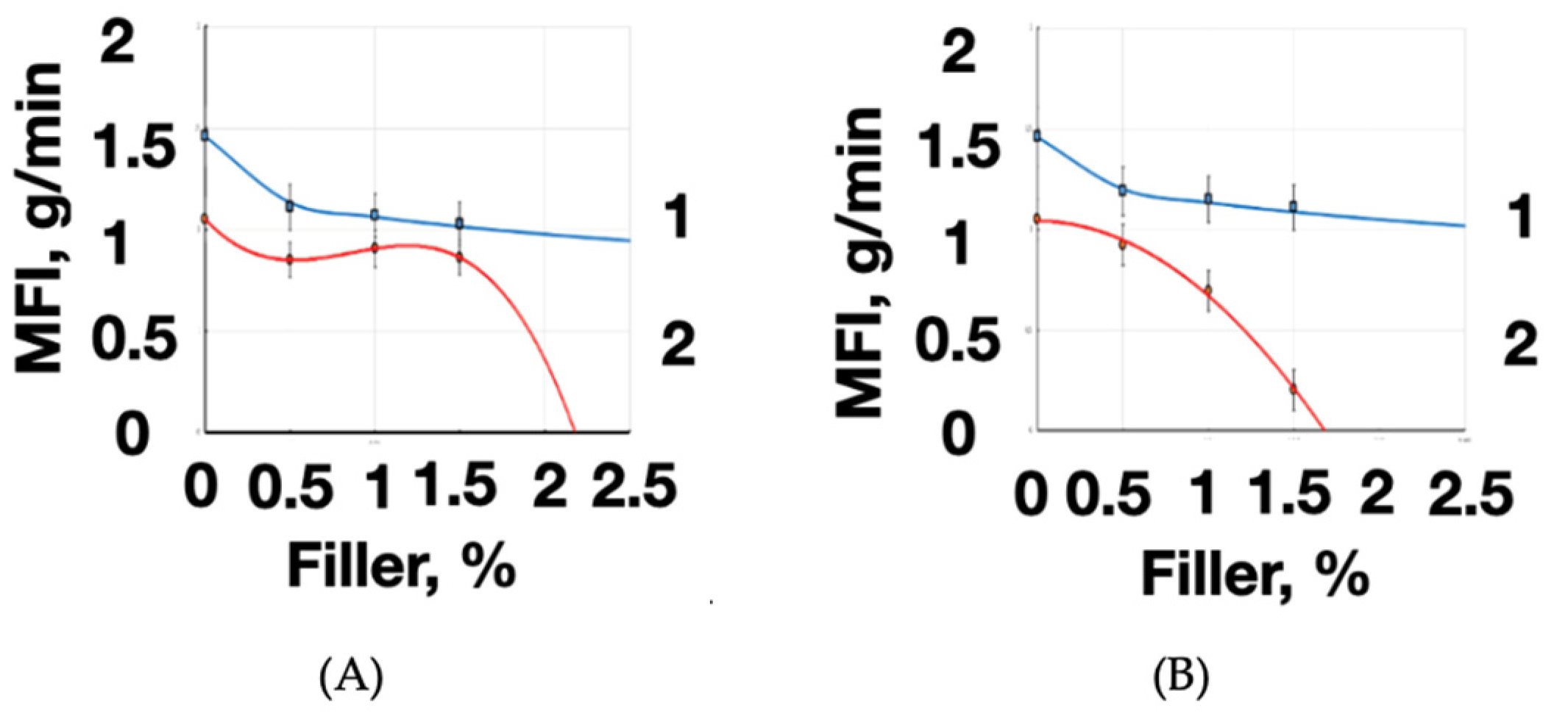
- The melt flow index value of the modified filament decreases with an increase in filler content proportion. The physical reason for the polymer material structure changes is, probably, the enlargement of the filler aggregates with an increase in their content in the polymer matrix (from 0 to 1.5 wt%). This contributes to the increased viscosity of local zone formation due to the elevated friction forces between the filler particles’ agglomerates. A further increase in the amount of filler can lead to the termination of bulk-modified filament extruding through the 3D printer nozzle.
- The MFI decreased by 18%–30% depending on the type and the mass fraction of the filler in the filament under consideration. The mass fraction of the filler is a technological parameter that limits the possibility of high-quality formation of 3D-printed products using material extrusion technology. The bulk modification of the PETG with the shungite (1.5 wt%) has such a significant effect on the viscosity and fluidity of the polymer composite melt that (with standard 3D-printing mode settings) various defects of products and printing difficulties occur (up to the malfunction of the extrusion unit). We’ve quantified the significance of the “filler mass fraction” for the “melt flow index” using the correlation analysis calculating technique.
- The «printing» defects (voids, non-prints, low interlayer adhesion of the filament, etc.) as well as pore networks may appear when using the shungite-modified (1.5 wt%) PETG (as well as other filled filaments) in 3D-printed product manufacturing. It leads to product model distortions and unexpected changes in the surface and other properties.
Author Contributions
Funding
Institutional Review Board Statement
Informed Consent Statement
Data Availability Statement
Acknowledgments
Conflicts of Interest
References
- Vasco, J.C. Additive manufacturing for the automotive industry. In Additive Manufacturing; Elsevier: Amsterdam, The Netherlands, 2021. [Google Scholar] [CrossRef]
- Azarov, A.V.; Antonov, F.K.; Golubev, M.V.; Khaziev, A.R.; Ushanov, S.A. Composite 3D printing for the small size unmanned aerial vehicle structure. Compos. Part B Eng. 2019, 169, 157–163. [Google Scholar] [CrossRef]
- Varepo, L.G.; Nagornova, I.V.; Doronin, F.A.; Gusev, S.V.; Bablyuk, E.B.; Nazarov, V.G. Testing, SEM-characterization and surface modification of gear wheels produced by additive and traditional technics. In Journal of Physics: Conference Series; IOP Publishing: Bristol, UK, 2019. [Google Scholar] [CrossRef]
- de Leon, A.C.C.; da Silva, Í.G.M.; Pangilinan, K.D.; Chen, Q.; Caldona, E.B.; Advincula, R.C. High performance polymers for oil and gas applications. React. Funct. Polym. 2021, 162, 104878. [Google Scholar] [CrossRef]
- Cholleti, E.R.; Gibson, I. ABS Nano Composite Materials in Additive Manufacturing. In IOP Conference Series: Materials Science and Engineering; IOP Publishing: Bristol, UK, 2018. [Google Scholar] [CrossRef]
- Dul, S.; Gutierrez, B.J.A.; Pegoretti, A.; Alvarez-Quintana, J.; Fambri, L. 3D printing of ABS Nanocomposites. Comparison of processing and effects of multi-wall and single-wall carbon nanotubes on thermal, mechanical and electrical properties. J. Mater. Sci. Technol. 2022, 121, 52–66. [Google Scholar] [CrossRef]
- Bazheryanu, V.V.; Zaychenko, I.V.; Zharikova, E.P. Local repair of parts from polymer composite material with the use of portable hot bonder control systems. In Materials Science Forum; Trans Tech Publications Ltd.: Stafa-Zurich, Switzerland, 2020. [Google Scholar] [CrossRef]
- Sheng, R. 3-D printing of airplane parts. In 3D Printing; Elsevier: Amsterdam, The Netherlands, 2022. [Google Scholar] [CrossRef]
- Hernandez, J.A.; Maynard, C.; Gonzalez, D.; Viz, M.; O’Brien, C.; Garcia, J.; Newell, B.; Tallman, T.N. The development and characterization of carbon nanofiber/polylactic acid filament for additively manufactured piezoresistive sensors. Addit. Manuf. 2022, 58, 102948. [Google Scholar] [CrossRef]
- Doronin, F.; Rytikov, G.; Evdokimov, A.; Rudyak, Y.; Taranets, I.; Nazarov, V. The Effect of Electro-Induced Multi-Gas Modification on Polymer Substrates’ Surface Structure for Additive Manufacturing. Processes 2023, 11, 774. [Google Scholar] [CrossRef]
- Doronin, F.A.; Nagornova, I.V.; Rytikov, G.O.; Varepo, L.G.; Nazarov, V.G. The general approach to the 3D-printing process quality estimation on the modified polymer substrates. In Journal of Physics: Conference Series; IOP Publishing: Bristol, UK, 2020; Volume 1546. [Google Scholar] [CrossRef]
- Bhagia, S.; Bornani, K.; Agarwal, R.; Satlewal, A.; Ďurkovič, J.; Lagaňa, R.; Bhagia, M.; Yoo, C.G.; Zhao, X.; Kunc, V.; et al. Critical review of FDM 3D printing of PLA biocomposites filled with biomass resources, characterization, biodegradability, upcycling and opportunities for biorefineries. Appl. Mater. Today 2021, 24, 101078. [Google Scholar] [CrossRef]
- Vidakis, N.; Mangelis, P.; Petousis, M.; Mountakis, N.; Papadakis, V.; Moutsopoulou, A.; Tsikritzis, D. Mechanical Reinforcement of ABS with Optimized Nano Titanium Nitride Content for Material Extrusion 3D Printing. Nanomaterials 2023, 13, 669. [Google Scholar] [CrossRef]
- Tirado-Garcia, I.; Garcia-Gonzalez, D.; Garzon-Hernandez, S.; Rusinek, A.; Robles, G.; Martinez-Tarifa, J.M.; Arias, A. Conductive 3D printed PLA composites: On the interplay of mechanical, electrical and thermal behaviours. Compos. Struct. 2021, 265, 113744. [Google Scholar] [CrossRef]
- Zhang, X.; Fan, W.; Liu, T. Fused deposition modeling 3D printing of polyamide-based composites and its applications. Compos. Commun. 2020, 15, 100413. [Google Scholar] [CrossRef]
- Valvez, S.; Silva, A.P.; Reis, P.N.B. Compressive Behaviour of 3D-Printed PETG Composites. Aerospace 2022, 9, 124. [Google Scholar] [CrossRef]
- Sam-Daliri, O.; Ghabezi, P.; Flanagan, T.; Finnegan, W.; Mitchell, S.; Harrison, N. Recovery of Particle Reinforced Composite 3D Printing Filament from Recycled Industrial Polypropylene and Glass Fibre Waste. In Proceedings of the World Congress on Mechanical, Chemical, and Material Engineering, Prague, Czech Republic, 31 July 31–2 August 2022. [Google Scholar] [CrossRef]
- McNiffe, E.; Ritter, T.; Higgins, T.; Sam-Daliri, O.; Flanagan, T.; Walls, M.; Ghabezi, P.; Finnegan, W.; Mitchell, S.; Harrison, N.M. Advancements in Functionally Graded Polyether Ether Ketone Components: Design, Manufacturing, and Characterisation Using a Modified 3D Printer. Polymers 2023, 15, 2992. [Google Scholar] [CrossRef] [PubMed]
- Doronin, F.A.; Rudyak, Y.V.; Rytikov, G.O.; Evdokimov, A.G.; Nazarov, V.G. 3D-printed planar microfluidic device on oxyfluorinated PET-substrate. Polym. Test. 2021, 99, 107209. [Google Scholar] [CrossRef]
- Rytikov, G.O.; Doronin, F.A.; Evdokimov, A.G.; Rudyak, Y.V.; Nazarov, V.G. The Effect of Morphological Surface Inhomogeneities on the Mycological Resistance of Polymer Films. Prot. Met. Phys. Chem. Surf. 2021, 57, 422–431. [Google Scholar] [CrossRef]
- Ghabezi, P.; Flanagan, T.; Harrison, N. Short basalt fibre reinforced recycled polypropylene filaments for 3D printing. Mater. Lett. 2022, 326, 132942. [Google Scholar] [CrossRef]
- Sam-Daliri, O.; Ghabezi, P.; Steinbach, J.; Flanagan, T.; Finnegan, W.; Mitchell, S.; Harrison, N. Experimental study on mechanical properties of material extrusion additive manufactured parts from recycled glass fibre-reinforced polypropylene composite. Compos. Sci. Technol. 2023, 241, 110125. [Google Scholar] [CrossRef]
- Pulipaka, A.; Gide, K.; Beheshti, A.; Bagheri, Z. Effect of 3D printing process parameters on surface and mechanical properties of FFF-printed PEEK. J. Manuf. Process. 2022, 85, 368–386. [Google Scholar] [CrossRef]
- Caputo, M.R.; Fernández, M.; Aguirresarobe, R.; Kovalcik, A.; Sardon, H.; Candal, M.V.; Müller, A.J. Influence of FFF Process Conditions on the Thermal, Mechanical, and Rheological Properties of Poly(hydroxybutyrate-co-hydroxy Hexanoate). Polymers 2023, 15, 1817. [Google Scholar] [CrossRef]
- ASTM D1238-23; Standard Test Method for Melt Flow Rates of Thermoplastics by Extrusion Plastometer. ASTM: West Conshohocken, PA, USA, 2023. [CrossRef]
- Kulichikhin, V.G.; Malkin, A.Y. The Role of Structure in Polymer Rheology: Review. Polymers 2022, 14, 1262. [Google Scholar] [CrossRef]
- Shi, K.; Cai, C.; Wu, Z.; Yong, J. Slicing and support structure generation for 3D printing directly on B-rep models. Vis. Comput. Ind. Biomed. Art 2019, 2, 3. [Google Scholar] [CrossRef]
- Haryńska, A.; Carayon, I.; Kosmela, P.; Brillowska-Dąbrowska, A.; Łapiński, M.; Kucińska-Lipka, J.; Janik, H. Processing of polyester-urethane filament and characterization of fff 3d printed elastic porous structures with potential in cancellous bone tissue engineering. Materials 2020, 13, 4457. [Google Scholar] [CrossRef]
- Manola, M.S.; Singh, B.; Singla, M.K.; Kumar, R. Investigation of melt flow index of dual metal reinforced ABS polymer for FDM filament fabrication. Mater. Today Proc. 2023. [Google Scholar] [CrossRef]
- Osswald, T.A.; Puentes, J.; Kattinger, J. Fused filament fabrication melting model. Addit. Manuf. 2018, 22, 51–59. [Google Scholar] [CrossRef]
- Vasilyev, I.; Ananyev, V.; Kolpakova, V.; Sardzhveladze, A. Development of technology for producing biodegradable hybrid composites based on polyethylene, starch, and monoglycerides. Fine Chem. Technol. 2021, 15, 44–55. [Google Scholar] [CrossRef]
- Yang, Y.; Zhang, C.; Wang, D.; Nie, L.; Wellmann, D.; Tian, Y. Additive manufacturing of WC-Co hardmetals: A review. Int. J. Adv. Manuf. Technol. 2020, 108, 1653–1673. [Google Scholar] [CrossRef]
- Rytikov, G.O.; Doronin, F.A.; Evdokimov, A.G.; Savel’ev, M.A.; Nazarov, V.G. An Approach to Structural and Functional Modeling of the Surface Morphology of Materials Based on Fluorinated Polymers. Russ. J. Gen. Chem. 2021, 91, 2667–2672. [Google Scholar] [CrossRef]
- Mohammadi Zerankeshi, M.; Sayedain, S.S.; Tavangarifard, M.; Alizadeh, R. Developing a novel technique for the fabrication of PLA-graphite composite filaments using FDM 3D printing process. Ceram. Int. 2022, 48, 31850–31858. [Google Scholar] [CrossRef]
- Nurul, M.S.; Mariatti, M. Effect of thermal conductive fillers on the properties of polypropylene composites. J. Thermoplast. Compos. Mater. 2013, 26, 627–639. [Google Scholar] [CrossRef]
- Saccenti, E.; Hendriks, M.H.W.B.; Smilde, A.K. Corruption of the Pearson correlation coefficient by measurement error and its estimation, bias, and correction under different error models. Sci. Rep. 2020, 10, 438. [Google Scholar] [CrossRef] [PubMed]


| Filler, wt% | Additive SEM Image (Color Corresponds to the Chemical Element) and Mapping of Chemical Elements on the Surface of the Transverse Cleavage of the Filament | Elemental Composition, wt% | |||||
|---|---|---|---|---|---|---|---|
| C | O | S | Mo | Al | Si | ||
| No filler | 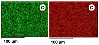 | 77 | 23 | - | - | - | - |
| MoS2 0.5 | 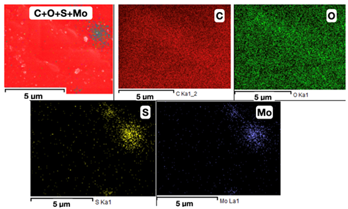 | 75.9 | 23.5 | 0.3 | 0.3 | - | - |
| MoS2 1.5 | 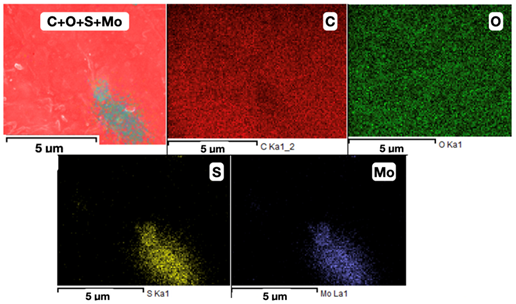 | 75.0 | 20.9 | 0.8 | 1.3 | - | - |
| Shungite 0.5 |  | 76.7 | 22.9 | - | - | 0.2 | 0.2 |
| Shungite 1.5 |  | 75.4 | 23.7 | - | - | 0.5 | 0.4 |
| Filament (Polymer + Filler) | Filler wt% | MFI IIRT-5 | MFI-MEX 3-D, g/min | MFIflow, % | ||
|---|---|---|---|---|---|---|
| g/10 min | g/min | |||||
| PETG | No filler | 0 | 14.6 | 1.46 | 1.0513 | 0 |
| Shungite | 0.5 | 11.9 | 1.19 | 0.9235 | 12.2 | |
| 1.0 | 11.5 | 1.15 | 0.6951 | 33.9 | ||
| 1.5 | 11.1 | 1.11 | 0.2036 | 80.6 | ||
| Molybdenum disulfide MoS2 | 0.5 | 11.1 | 1.11 | 0.8509 | 19.1 | |
| 1.0 | 10.7 | 1.07 | 0.9068 | 13.7 | ||
| 1.5 | 10.3 | 1.03 | 0.8623 | 18.0 | ||
| Coefficients of Paired Correlations | Filler, wt% | MFI IIRT-5, g/min | MFI MEX 3D, g/min |
|---|---|---|---|
| Filler, wt% | 1 | −0.87 ± 0.08 | −0.72 ± 0.07 |
| MFI IIRT-5, g/min | −0.87 ± 0.08 | 1 | 0.94 ± 0.09 |
| MFI MEX 3D, g/min | −0.72 ± 0.07 | 0.94 ± 0.09 | 1 |
| Coefficients of Paired Correlations | Filler, wt% | MFI IIRT-5, g/min | MFI MEX 3D, g/min |
|---|---|---|---|
| Filler, wt% | 1 | −0.89 ± 0.09 | −0.96 ± 0.09 |
| MFI IIRT-5, g/min | −0.89 ± 0.09 | 1 | 0.74 ± 0.08 |
| MFI MEX 3D, g/min | −0.96 ± 0.09 | 0.74 ± 0.08 | 1 |
| Filament (Polymer + Filler) | Digital Image | Model | Morphological Spectrum | Maximum Amplitude |
|---|---|---|---|---|
| PETG (no filler) | 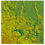 | 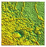 |  | 10.5 ± 0.7 |
| PETG + shungite 1.5 wt% | 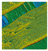 | 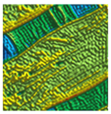 | 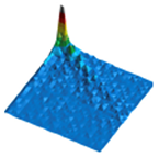 | 19 ± 2 |
Disclaimer/Publisher’s Note: The statements, opinions and data contained in all publications are solely those of the individual author(s) and contributor(s) and not of MDPI and/or the editor(s). MDPI and/or the editor(s) disclaim responsibility for any injury to people or property resulting from any ideas, methods, instructions or products referred to in the content. |
© 2023 by the authors. Licensee MDPI, Basel, Switzerland. This article is an open access article distributed under the terms and conditions of the Creative Commons Attribution (CC BY) license (https://creativecommons.org/licenses/by/4.0/).
Share and Cite
Doronin, F.; Rudakova, A.; Rytikov, G.; Nazarov, V. Simple Determination of the Melt Flow Index of Composite Polymer Filaments Used in Material Extrusion Additive Manufacturing. Coatings 2023, 13, 1592. https://doi.org/10.3390/coatings13091592
Doronin F, Rudakova A, Rytikov G, Nazarov V. Simple Determination of the Melt Flow Index of Composite Polymer Filaments Used in Material Extrusion Additive Manufacturing. Coatings. 2023; 13(9):1592. https://doi.org/10.3390/coatings13091592
Chicago/Turabian StyleDoronin, Fedor, Anna Rudakova, Georgy Rytikov, and Victor Nazarov. 2023. "Simple Determination of the Melt Flow Index of Composite Polymer Filaments Used in Material Extrusion Additive Manufacturing" Coatings 13, no. 9: 1592. https://doi.org/10.3390/coatings13091592
APA StyleDoronin, F., Rudakova, A., Rytikov, G., & Nazarov, V. (2023). Simple Determination of the Melt Flow Index of Composite Polymer Filaments Used in Material Extrusion Additive Manufacturing. Coatings, 13(9), 1592. https://doi.org/10.3390/coatings13091592