Abstract
Hydrogen barrier coatings with Al2O3 as the main component are a good choice for solving the hydrogen embrittlement problem during hydrogen transportation in long-distance pipelines. However, the difference in the coefficients of thermal expansion between the substrate and the Al2O3 coating limits its further utilisation and development. In this study, rare earth oxides were added to the molten aluminium solution, and a Fe-Al transition layer was introduced on the surface of X80 steel by hot-dip plating to solve the thermal mismatch. Here, the microstructure and bonding strength of the hot-dip aluminium layer were investigated. It is found that the hot-dip aluminium coating consists of the outermost aluminium-rich layer and the inner Fe-Al alloy layer, and the microstructure of the two will change with the change in dip plating parameters. The best overall performance of the hot-dip aluminium layer was obtained from X80 steel substrate at a dip plating temperature of 700 °C and a dip plating time of 5 min. This coating has a good interface, moderate thickness, and a bond strength of 49 N. This study provides a reference value for solving the thermal mismatch between the steel substrate and the Al2O3 hydrogen barrier coating generated by subsequent anodising.
1. Introduction
Hydrogen is regarded as a potential candidate for future energy. Many obstacles need to be overcome before hydrogen can be widely used. The delivery cost is one of the key components of the hydrogen fuel cost. Long-distance delivery using the existing natural gas pipelines is the most economical and reliable delivery way for hydrogen. However, the pipeline steels are prone to hydrogen embrittlement in hydrogen-rich environments, which seriously affects the life of the pipeline [1]. Constructing a hydrogen barrier coating on the surface of pipeline steel could effectively reduce the infiltration of hydrogen and the risk of hydrogen embrittlement and fatigue damage during hydrogen transport [2].
Researchers have favoured oxide ceramic coatings due to their high hydrogen penetration factor, chemical stability, and corrosion resistance [3]. Among them, hydrogen barrier coatings with Al2O3 as the main component have received wide attention due to the advantages of low cost, simple preparation process, and excellent overall performance [4,5,6]. However, due to the large difference in the coefficient of thermal expansion between Al2O3 and pipeline steel, Al2O3 coatings are prone to cracking and flaking. During long-distance hydrogen transmission, this phenomenon can lead to hydrogen penetration and hydrogen cracking, which can lead to major accidents. Introducing a transition layer between the substrate and the one-component Al2O3 coating is one of the ways to alleviate the problem of mismatch between the coefficient of thermal expansion of the hydrogen-resistant coating and the substrate.
The Fe-Al alloy layer has excellent resistance to high temperature and corrosion and has good suitability and wettability with the Al2O3 coating. Moreover, the alloy layer can improve the bonding strength between the metal substrate and the coating. The Fe-Al/Al2O3 coating can be prepared on the steel substrate through hot-dip aluminium plating and anodic oxidation [7]. No interfacial phase is generated between the two contact surfaces, no chemical reaction is generated, and the interfacial bonding is good, so it can be used as a transition layer between the steel substrate and the Al2O3 coating [8]. Huang et al. prepared Fe-Al/Al2O3 composite hydrogen-blocking coating on 316L stainless steel substrate; the Fe-Al layer effectively mitigated the thermal mismatch between the Al2O3 coating and the substrate [9].
The research shows that the compositions and properties of the Fe-Al transition layer have an important influence on the hydrogen barrier properties and strength of the subsequently prepared Al2O3 layer. Han et al. found that the morphology of the intermetallic layer of molten aluminium changed after the addition of silicon to the molten aluminium solution, and the coating preparation for hydrogen/tritium was improved [10]. He et al. prepared α-Al2O3(CrO)/Fe-Al composite coatings on the surface of 316L stainless steel using a new process, which reduced hydrogen permeation by 3–4 orders of magnitude compared to the base material [11].
It is considered that while introducing a Fe-Al alloy layer on the surface of the steel substrate by hot-dip aluminium plating, it is possible to influence the compositional composition of the coating by using rare earth elements. The hydrogen barrier properties of the coating can be well improved by adding rare earth elements with hydrogen barrier properties. Sun et al. found that co-doping of La2O3 and Ce2O3 reduced the adsorption energy of Al2O3 for hydrogen molecules, and the Al2O3 coatings prepared by using hot-dip plating had good hydrogen-blocking properties [12]. Liu et al. improved the high-temperature stability and hydrogen barrier properties of Al2O3 coatings by doping different proportions of ZrO into the Al2O3 coatings [13]. Therefore, in this study, two rare earth oxides (La2O3 and Ce2O3) were melted together with pure aluminium, and a Fe-Al alloy layer was introduced on the surface of the X80 steel substrate using hot-dip plating of aluminium. In this way, the hydrogen barrier properties of the coating were enhanced while solving the thermal mismatch problem. Based on the addition of rare earth elements, the micro-morphology of the hot-dip aluminium layer and the coating bond strength were analysed to study the effects of various process parameters on the coating.
2. Experimental Materials and Methods
2.1. Experimental Materials
The substrate used for the hot dip plating test was X80 steel with 99.99% purity and chemical composition, as shown in Table 1. In hot dip aluminium plating, commercially pure aluminium ingot (99.99%) was used as the raw material, and equal-proportion La2O3 and Ce2O3 mixed particles with a size of 45 μm were doped into the aluminium melt [12].

Table 1.
Chemical composition and content of X80 steel (wt.%).
2.2. Preparation of Hot-Dip Aluminium Layers
The size of the X80 pipeline steel specimen is 25 mm × 25 mm × 2 mm. Before hot dip aluminium plating, the specimens were polished through 400#, 800#, and 1200# SiC sandpaper, and after that, placed in anhydrous ethanol for ultrasonic cleaning to remove the surface adherence of sand and other impurities. The specimens were sequentially put into a 20% mass fraction of NaOH solution, a 15% HCl solution to remove oil and rust, and then put into a 6% KF + 2% ZnCl2 solution to help plating, and finally rinsed and dried. The NBD-M1500 box-type resistance furnace was used to conduct hot-dip aluminium plating experiments on pre-treated X80 steel specimens. Pure aluminium ingots are heated in a furnace after being placed in a ceramic crucible together with a homogeneous mixture of rare earth oxide powders (La2O3, Ce2O3). After the aluminium ingot was completely melted, the slag was stripped. Then, the pre-treated specimens were put into the aluminium solution at a uniform speed, put out at a uniform speed after dip-plating for a specific time, and cooled naturally in the air.
The morphology of the hot-dip aluminium coatings was investigated using a JSM-7200F thermal field scanning electron microscope (JEOL, Japan). The elemental composition and distribution of the coatings were analysed using an energy spectrometer (EDS, OXFORD, UK) coupled with a scanning electron microscope. The phase composition of the coatings was analysed using X-ray diffraction (XRD, Panalytical X’Pert PRO, Shimadzu corporation). The coating bonding strength of the hot dip-plated aluminium coatings was tested using a WS-2005 automatic scratch tester( Lanzhou Institute of ChemicalPhysics, Chinese Academy of Sciences, China) for coating adhesion.
3. Results and Discussion
3.1. Micro-Morphological Observation of Hot-Dip Aluminium Coatings
Figure 1 shows the surface morphology of the hot-dip aluminium coatings. As shown in Figure 1a, the surface of the hot-dip coatings has a small number of tiny holes and a large number of white needles. The surface scanning results show a surface aluminium content of 95.4%, with the rest being mainly O and Fe elements. As shown in the EDS surface scanning diagrams (c) and (d), the white needles are mainly composed of Fe and Al elements, which are analysed to be probably Fe-Al alloys produced by mutual diffusion of the steel matrix in contact with the aluminium liquid. During hot-dip aluminium plating, the diffusion between atoms continues to increase, resulting in a change in surface morphology. As the diffusion intensifies, the FeAl3 phase formed on the surface of the steel matrix is replaced by a new alloy phase, which enters the aluminium-rich layer in a broken-free state. The FeAl3 phase in the broken-free state shows a white needle-like morphology on the surface. In addition, the rare earth elements La and Ce are uniformly distributed on the surface.
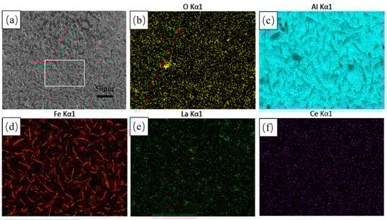
Figure 1.
Surface morphology and EDS surface scans of hot-dip aluminium plating layer (a) microscopic morphology; (b) O EDS; (c) Al EDS; and (d) Fe EDS; (e) La EDS; (f) Ce EDS.
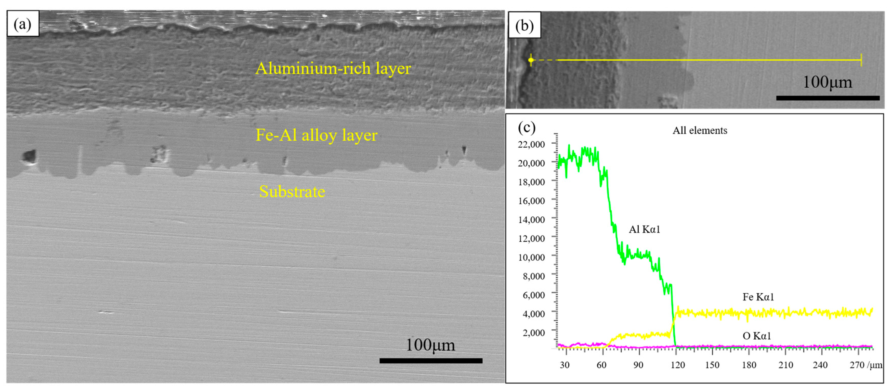
To further investigate the structure of the coating, the cross-section of the hot-dip aluminium layer was observed, as shown in Figure 2. The coating mainly consists of a dark grey aluminium-rich layer on the surface and a light grey Fe-Al alloy layer in the inner part. The surface aluminium-rich layer is not produced during dip-plating but adheres to the surface of the specimen during the lifting of the specimen out of the molten aluminium solution. The thickness of the aluminium-rich layer formed is mainly influenced by the viscosity of the liquid aluminium and the lifting speed.

Figure 2.
Cross-sectional morphology and EDS line scan of hot-dip aluminium coating (a) cross-sectional morphology; (b) line scan morphology; (c) line scan results.
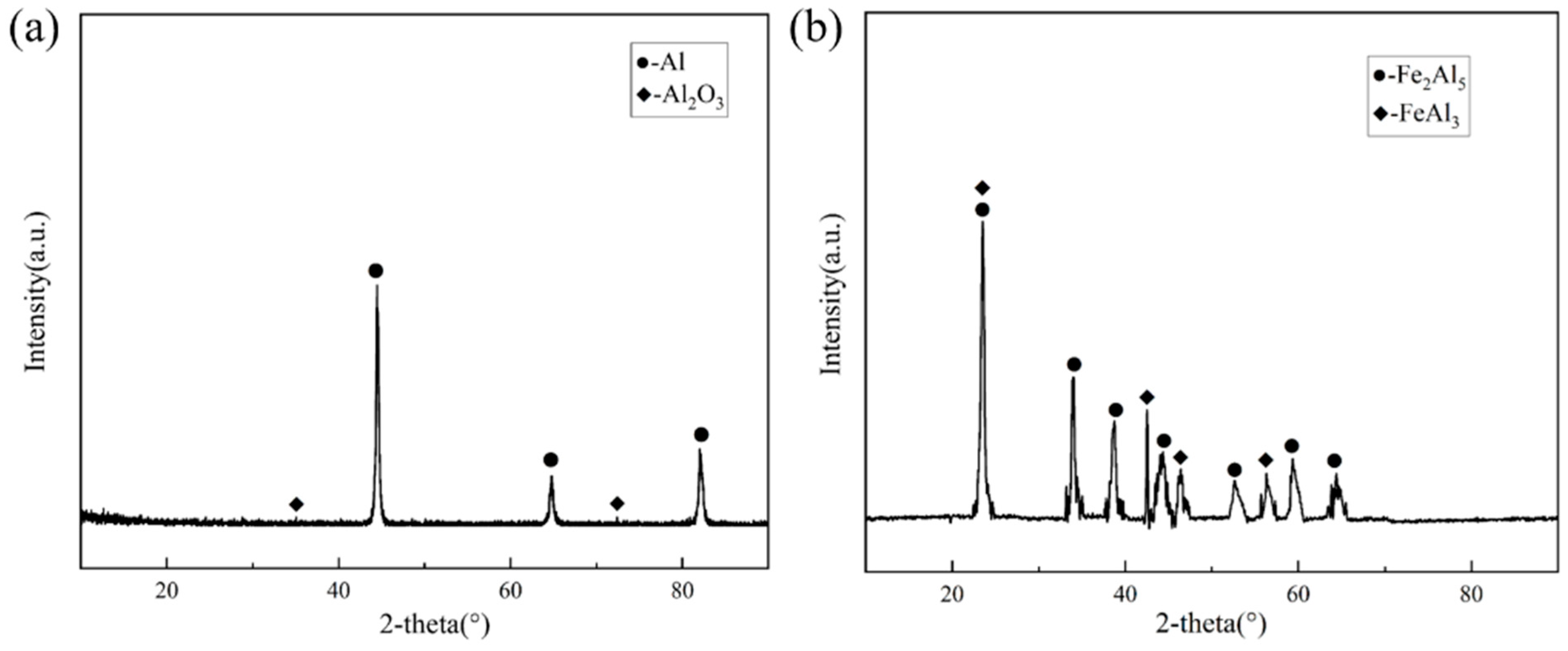
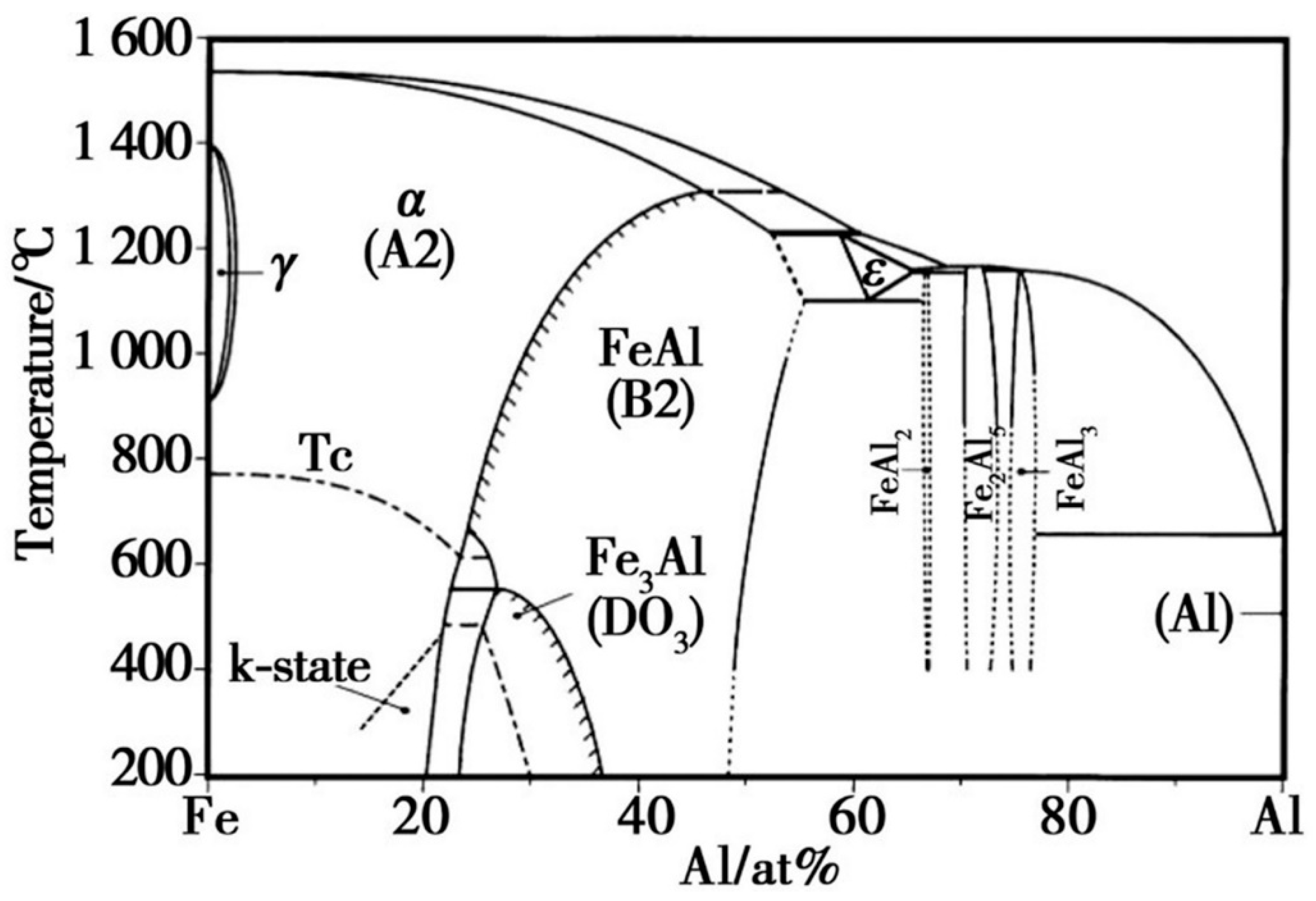
Since the outermost part of the hot-dip plating layer is an aluminium-rich layer, the sample was immersed in a 1 mol/L NaOH solution to investigate the compositional composition of the Fe-Al alloy layer using XRD. After the aluminium-rich layer was completely removed from its surface, the exposed Fe-Al alloy layer was analysed. Figure 3 shows the XRD results of the two layers, respectively. As shown in Figure 3a, the surface aluminium-rich layer is mainly composed of Al, and part of the Al is oxidised to Al2O3 by air. Figure 3b shows that the main compositions of the Fe-Al alloy layer were the Fe2Al5 phase and FeAl3 phase. The formation of these two phases is related to the diffusion process of Fe and Al atoms. Combined with the binary phase diagram in Figure 4, the molten aluminium solution diffuses with the partially melted steel substrate during the hot dip aluminium plating process. The intermediate layer formed by diffusion contains between 70% and 75% aluminium atoms, resulting in the formation of the Fe2Al5 and FeAl3 phases at 700 °C. The Fe2Al5 and FeAl3 phases are formed at 700 °C. The formation mechanism of these two phases is that the iron and aluminium atoms diffuse into each other, first forming the low iron content FeAl3 phase with an aluminium atom saturation of 75%. With further diffusion of matrix iron, a high iron content Fe2Al5 phase is formed [14,15].
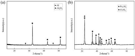
Figure 3.
XRD results (a) XRD results of the surface aluminium-rich layer; (b) XRD results of the Fe-Al layer.
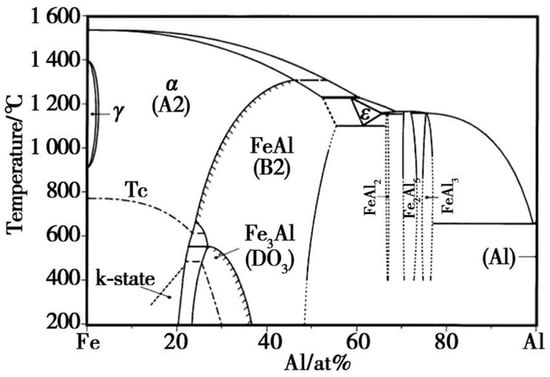
Figure 4.
Fe-Al binary phase diagram.
3.2. Effect of Different Dip-Plating Parameters on the Microstructure of Coatings
3.2.1. Effect of Dip-Plating Temperature on the Microstructure of Coatings
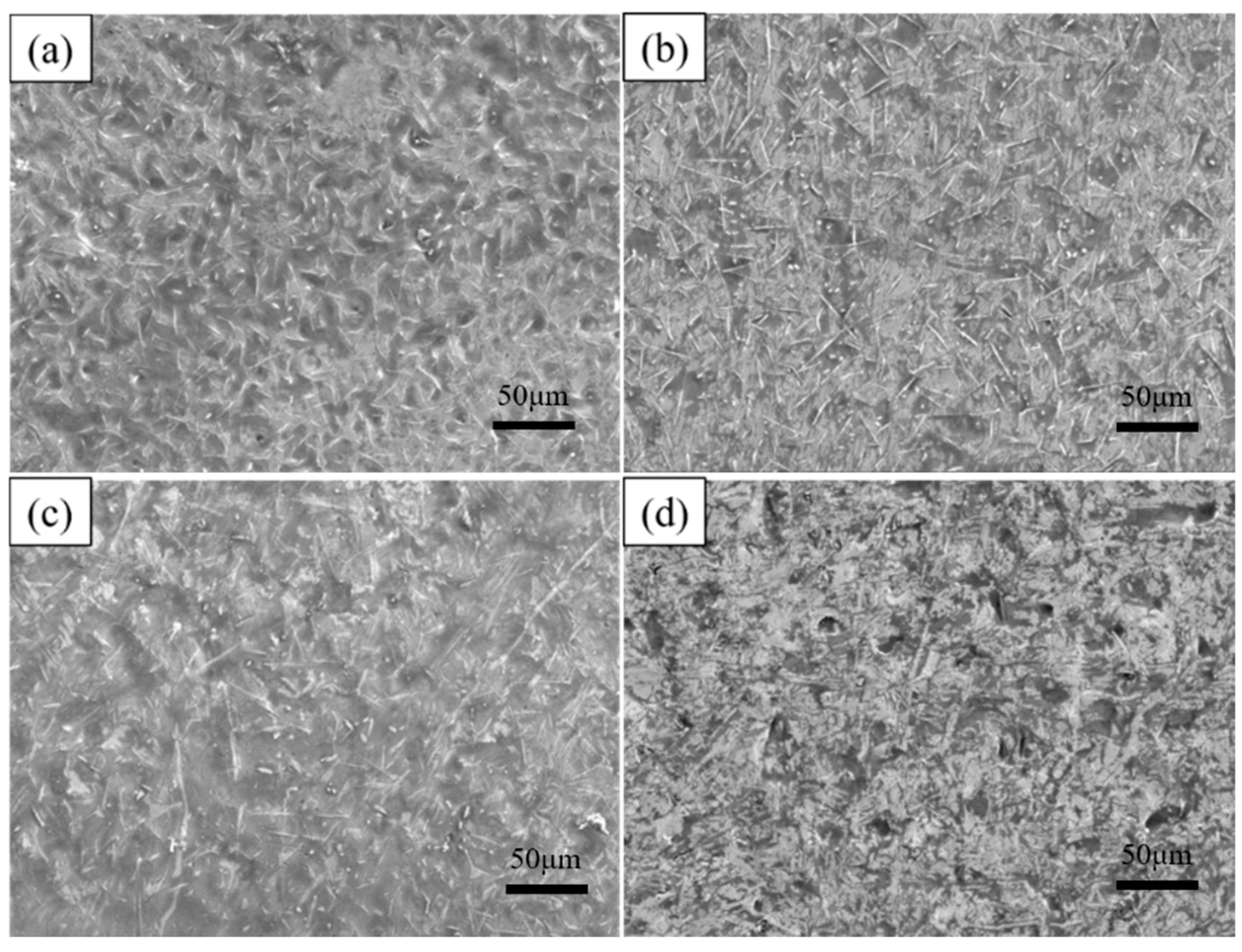
As shown in Table 2, to investigate the effect of dip-plating temperature on the microstructure of the coating, the substrate was dip-plated at 700 °C, 750 °C, 775 °C, and 800 °C for 5 min with a mass fraction of 6% KF + 2% ZnCl2 solution as the auxiliary plating agent and 0.5 wt.% of La2O3 and Ce2O3 rare earth oxides added, respectively. The specimens after hot dip plating are shown in Figure 5, and the number of white needle-like FeAl3 phases in the surface aluminium-rich layer tended to increase and decrease with an increase in dip plating temperature. The overall phase appearance of the plated layer is uniform and dense between 700 °C and 775 °C, while the microscopic defects, such as holes on the surface, increase when the temperature reaches 800 °C. This is because diffusion between Fe and Al atoms occurs mainly by the mechanism of vacancies. The number of vacancies is constant at a certain temperature, and as the temperature increases, the concentration of equilibrium vacancies increases, the thermal movement of Fe and Al atoms is enhanced, and the rate of diffusion is accelerated. The increase in the amount of FeAl3 phase is due to the fragmentation of the FeAl3 phase into the aluminium-rich layer. At first, more FeAl3 phases fragmented into the surface aluminium-rich layer due to the increase in temperature, leading to an increase in the number of FeAl3 phases. However, with a further increase in temperature, the rate and concentration of Fe atoms diffuse into the aluminium liquid increase, causing part of the FeAl3 phase to convert to the Fe2Al5 phase, and the number of FeAl3 phases decreases. The high temperature will reduce the viscosity of the aluminium liquid, increase the fluidity, and cause leakage of plating and pinholes, as well as other defects; the surface layer oxidation is more serious. So, the viscosity of the aluminium liquid is easily affected by the dip plating temperature; too high a dip plating temperature will make the quality of the plating layer decline.
Table 2.
Hot-dip aluminium plating test by changing the plating temperature.

Figure 5.
Surface morphology at different dipping temperatures (a) 700 °C, (b) 750 °C, (c) 775 °C, (d) 800 °C.
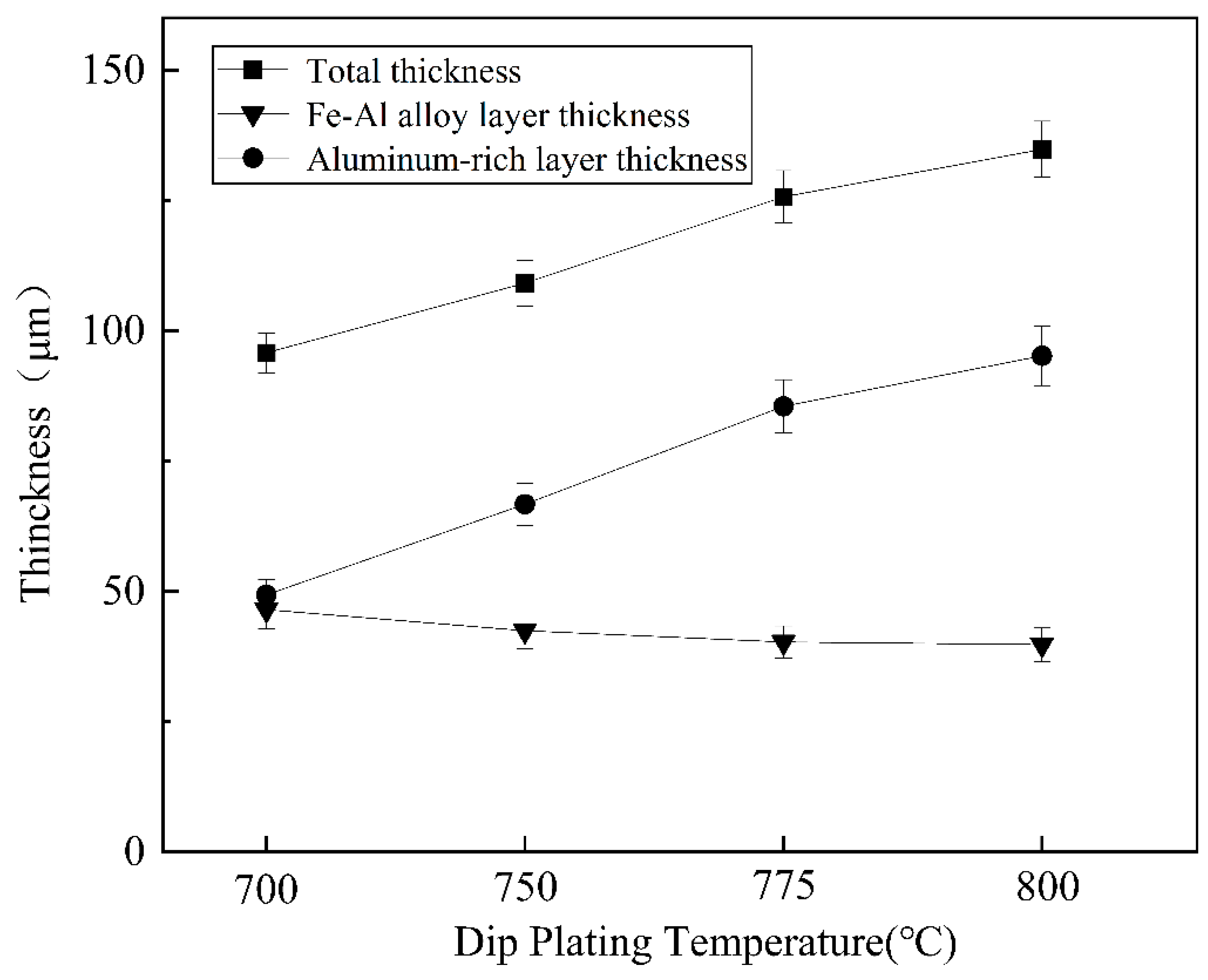
As shown in Figure 6, the total thickness of the plated layer shows an increasing trend with increasing dip plating temperature, while the thickness of the surface aluminium-rich layer decreases slightly and the thickness of the intermediate Fe-Al alloy layer increases significantly. The aluminium-rich layer on the surface is formed by adhesion during the lifting and pulling process. As the liquid aluminium fluidity increases with temperature, the liquid aluminium adhering to the surface of the specimen is more likely to slip off, which leads to a reduction in the thickness of the aluminium-rich layer. The Fe-Al alloy layer is formed by the mutual diffusion of aluminium atoms in the molten aluminium liquid and iron atoms in the steel matrix. As the temperature rises, the more Fe-Al metal compounds are formed by diffusion, the greater the thickness of the intermediate alloy layer. At the same time, as shown in Figure 7, the increase in microscopic defects, such as holes, is due to the increase in oxide inclusions in the aluminium liquid due to the increase in temperature and the inability of the aluminium liquid to form a good wetting with the substrate. When cooling down the high-temperature aluminium liquid produces volume contraction, the microscopic stress leads to an increase in microscopic defects.
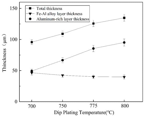
Figure 6.
Variation in coating thickness at different dipping temperatures.

Figure 7.
Cross-section morphologies at different dipping temperatures (a) 700 °C, (b) 750 °C, (c) 775 °C, (d) 800 °C.
3.2.2. Effect of Dip-Plating Times on the Microstructure of Coatings
As shown in Table 3, this study is continued by varying the dip plating temperature. The surface morphology of the coatings after dip plating at a temperature of 700 °C for 2 min, 5 min, 10 min, and 15 min is shown in Figure 8. With an increase in dip-plating time, the number of white needle-like FeAl3 phases decreases, the size becomes smaller, and the microscopic defects, such as surface holes, increase. When the steel substrate begins to be immersed in the aluminium liquid, the interface temperature is low, and the number of Fe atoms diffusing out is small, so a layer of FeAl3 phase is first formed on the surface of the steel substrate. With the mutual diffusion between iron and aluminium atoms, the Fe2Al5 phase grows rapidly, leading to the fragmentation of the FeAl3 phase and the consumption of the part of the FeAl phase. Therefore, with the increase in dip-plating time, part of the FeAl3 phase is converted to the Fe2Al5 phase, resulting in a decrease in its quantity and size. At the same time, metal oxide inclusions in the aluminium solution increase, leading to holes and increased oxidation.
Table 3.
Hot-dip aluminium plating test with varying dipping time.
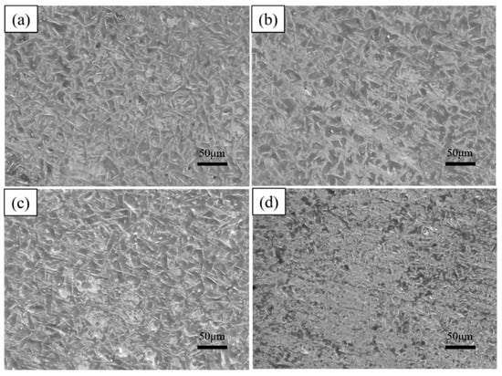
Figure 8.
Surface morphologies at different dipping times (a) 2 min, (b) 5 min, (c) 10 min, (d) 15 min.
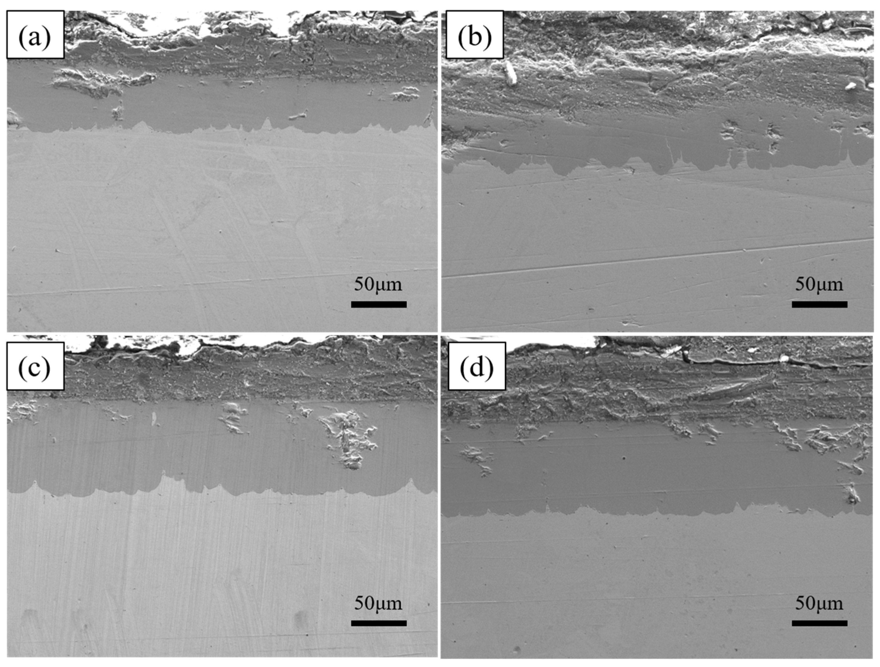
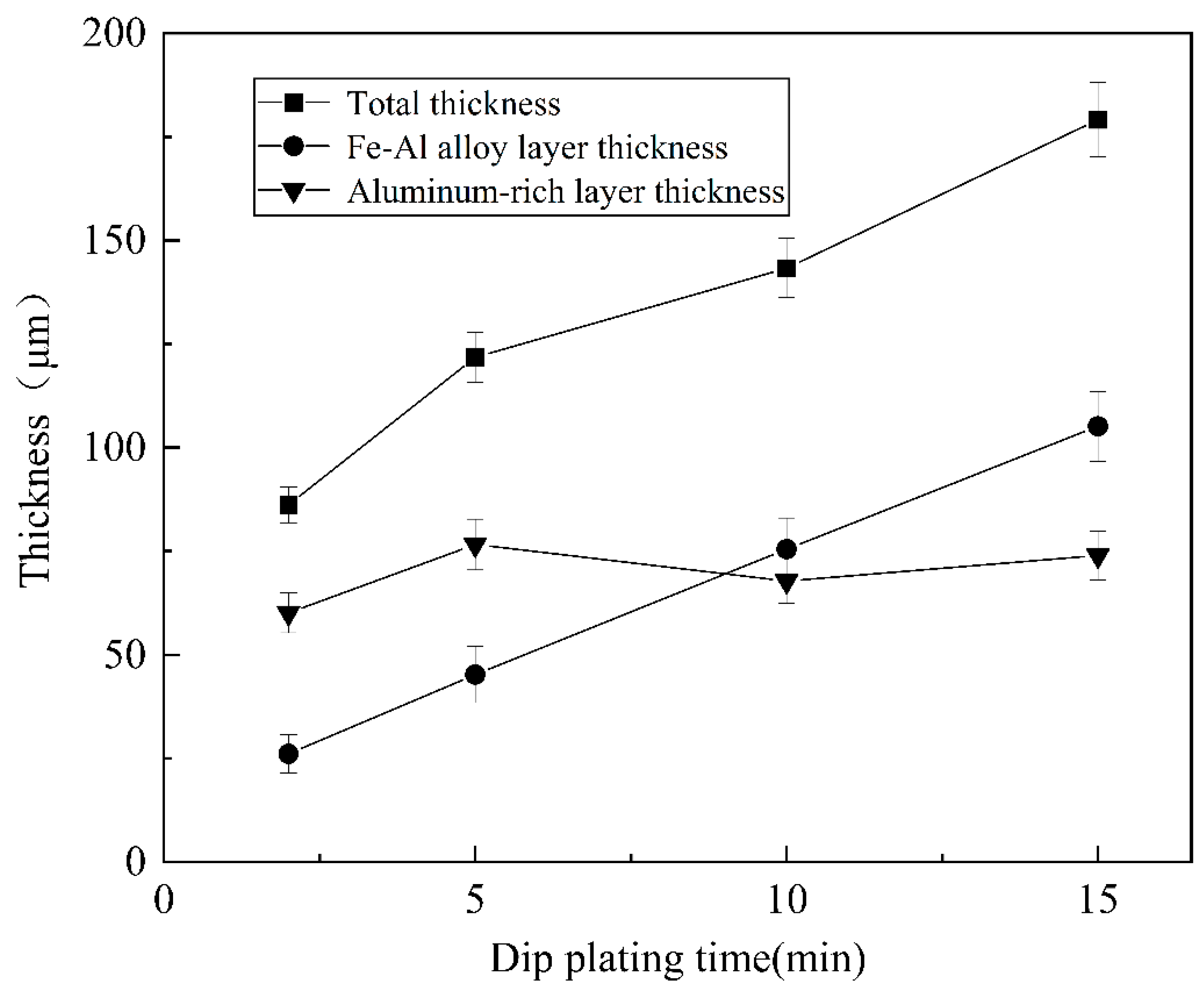
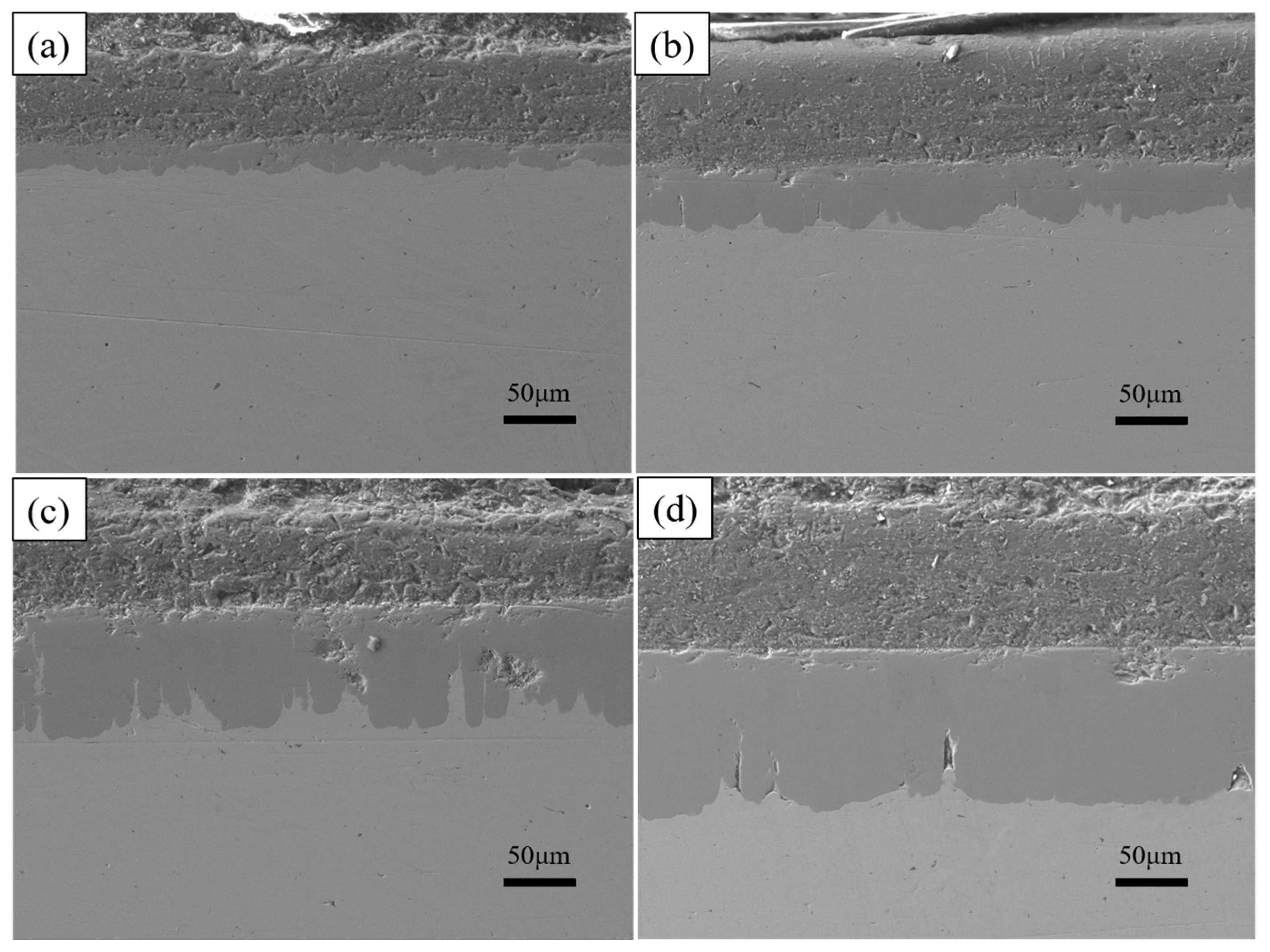
As shown in Figure 9, the thickness of the aluminium-rich layer on the surface varies slightly with increasing dip-plating time, and the thickness of the inner iron–aluminium alloy layer thickens significantly. The thickness of the aluminium-rich layer on the surface is mainly influenced by the lifting speed, independent of the dip-plating time, but the manually controlled lifting speed is prone to small errors, leading to fluctuations in the surface thickness. Figure 10 shows the cross-sectional morphology at different dip-plating times. With the increase in dip plating time, the iron and aluminium atoms continuously diffuse with each other, resulting in the Fe2Al5 phase continuously growing inside the steel matrix in a tooth-like manner and the thickness of the alloy layer increasing rapidly. Microscopic defects such as holes in the aluminium-rich and alloy layers did not produce significant changes with time. The diffusion of Fe-Al elements at the junction of the two gradually tends to be stable with an increase in time, so the interfacial demarcation line between the Fe-Al alloy layer and the surface aluminium-rich layer becomes more and more obvious and straight with the prolongation of time.
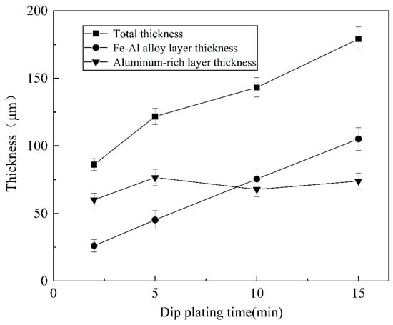
Figure 9.
Variation in coating thickness under different dipping times.

Figure 10.
Cross-section morphologies at different dipping times (a) 2 min; (b) 5 min; (c) 10 min; (d) 15 min.
3.2.3. Effect of the Addition of Rare Earth Oxides on the Microstructure of Coatings
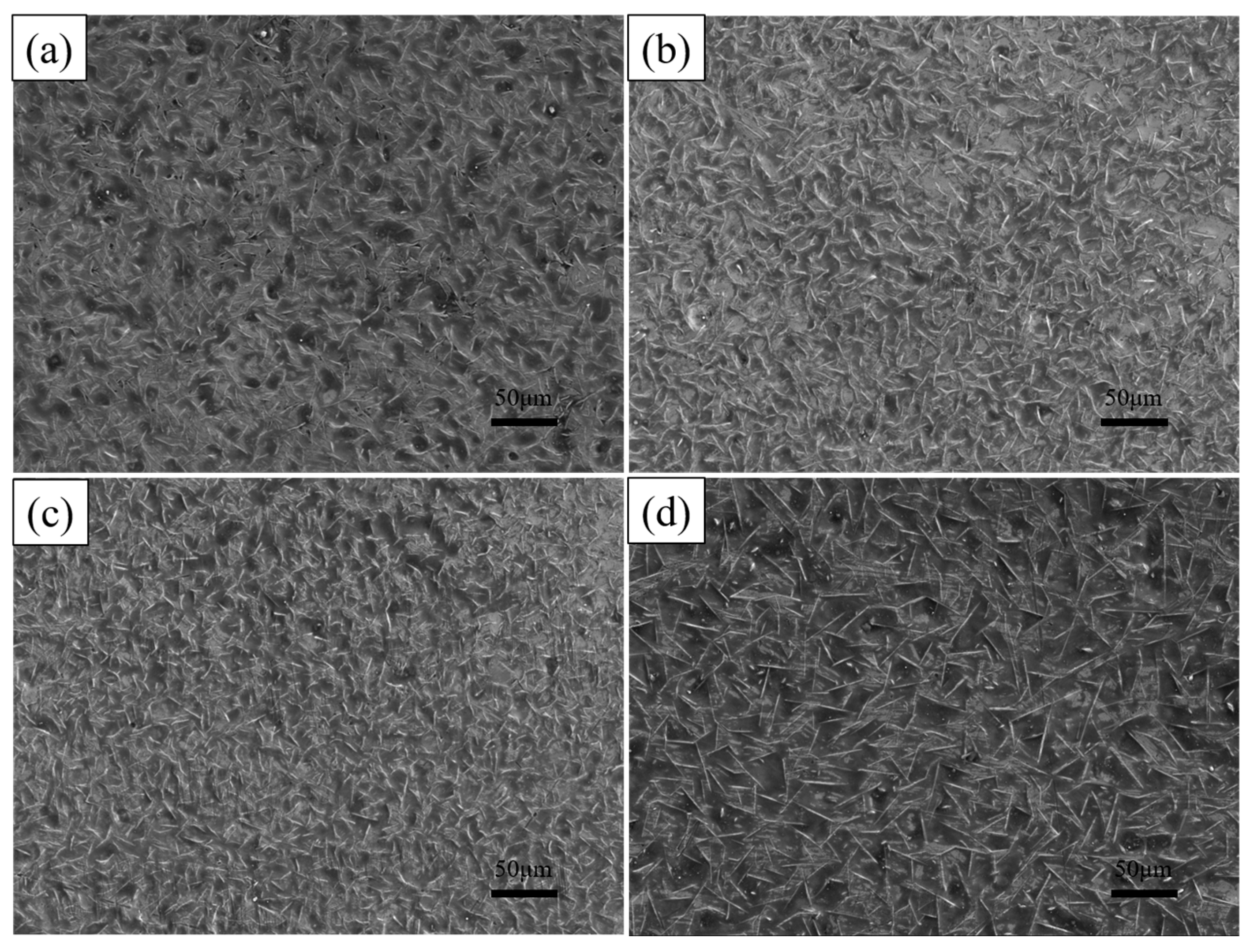
The hot-dip plating experiments were continued on the substrate according to the process parameters shown in Table 4. Figure 11 shows the surface morphology of the plated layer after adding different mass fractions of rare earth oxides. It can be seen from the figure that the size of the white needle-like FeAl3 phase on the surface decreases and then increases with the addition of rare earth oxides, and micro-defects such as holes and depressions on the surface show the same trend. The reason is that with the addition of rare earth oxides, La2O3 and Ce2O3 particles are diffusely distributed in the aluminium liquid. They are in the form of the second phase of the FeAl3 phase growth and expansion of the hindering effect, thus playing the role of grain refinement. The FeAl3 phase belongs to the impurity phase, the refinement of impurities to help improve the toughness of the coating and plasticity, prevent the expansion of cracks, and so on.
Table 4.
Hot-dip aluminium plating test with varying rare earth additions.

Figure 11.
Surface morphologies of hot-dip aluminium plating layers with different supplemental amounts of rare earth oxides (a) 0%; (b) 0.2%; (c) 0.5%; (d) 1%.
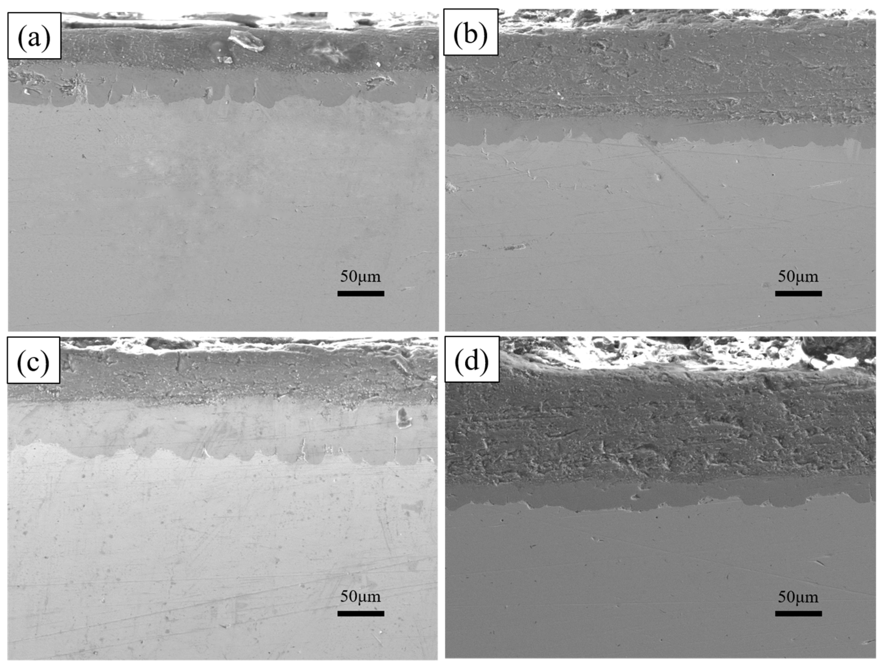
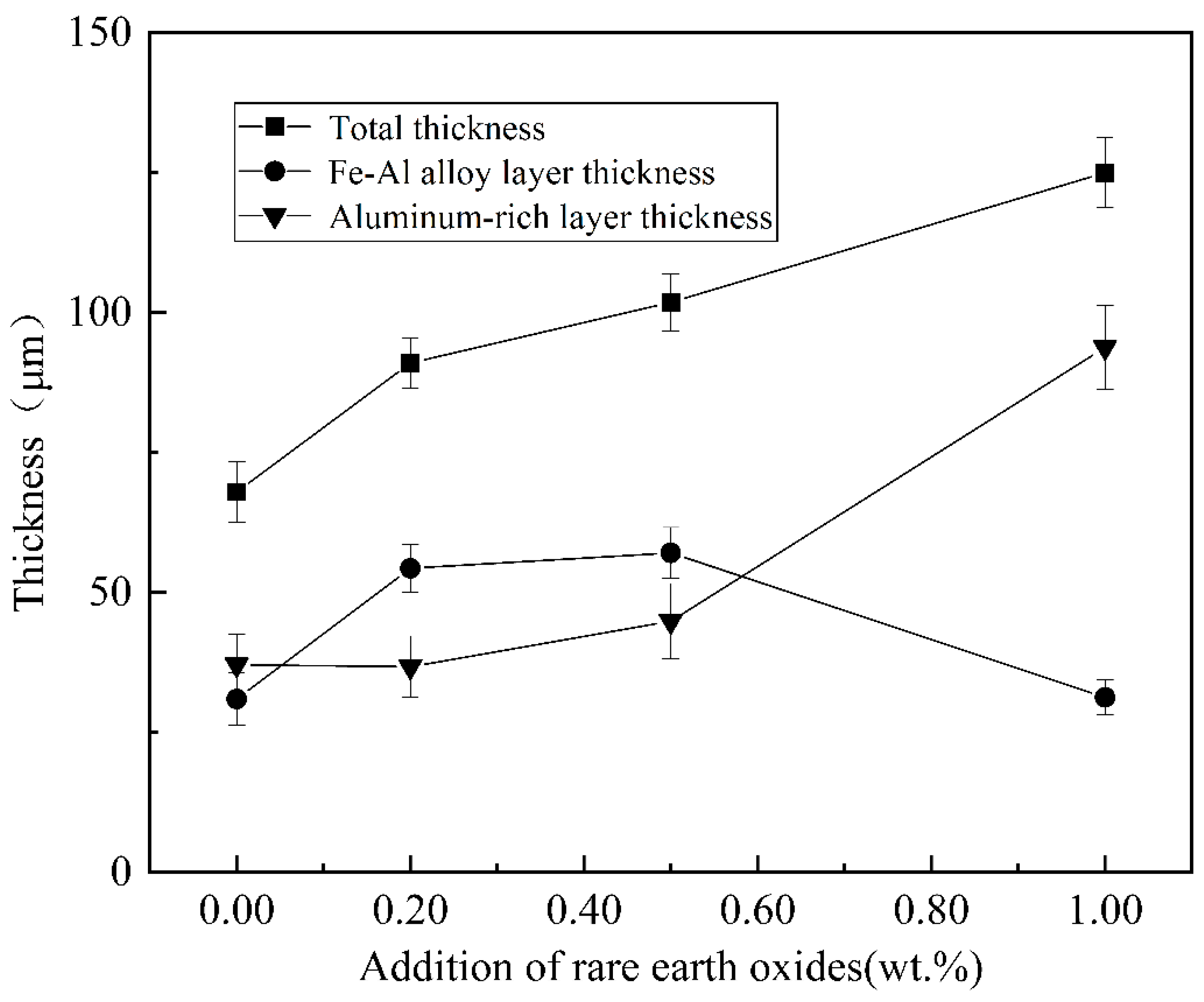
The cross-sectional morphology of the plated layers with different rare earth oxide contents was analysed, as shown in Figure 12. With the increase in rare earth oxides, the aluminium-rich layer and the alloy layer first become smooth and flat, and the morphology is better when the addition of rare earth oxides is 0.5%, and with the further increase in the addition, the defects such as holes and looseness in the plating layer increase. The thickness of the alloy layer is summarised in Figure 13, with the increase in rare earth oxides generally showing a trend of thickening and then thinning, while the thickness of the aluminium-rich layer changes in the opposite trend, generally showing a trend of thinning and then thickening.

Figure 12.
Cross-section morphologies of hot-dip aluminium plating layer with different addition amounts of rare earth oxides (a) 0%; (b) 0.2%; (c) 0.5%; (d) 1%.
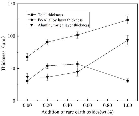
Figure 13.
Variation in coating thickness with different rare earth oxide content.
The addition of moderate amounts of rare earth elements is conducive to the mutual diffusion of Fe-Al atoms, which produces a catalytic effect and promotes the growth of the alloy layer. In addition, an appropriate amount of rare earth oxides can also fill the holes caused by the uneven distribution of aluminium liquid, improve the overall densification of the plating layer, as well as reduce the natural oxidation of the surface and the process of hydrogen penetration. When intentional oxides are added in excess, the diffusion of iron and aluminium atoms is impeded, inhibiting alloy layer growth. It not only reduces the fluidity of the aluminium solution but also raises the viscosity of the aluminium solution and increases the thickness of the aluminium-rich layer on the surface. It also produces agglomeration phenomena, leading to an increase in defects such as holes. The addition of rare earth oxide particles can act as the core of crystallisation, reduce the critical nucleation work, refine the grains, and make the plating layer smooth.
3.3. Bonding Strength of Hot-Dip Aluminium Coatings
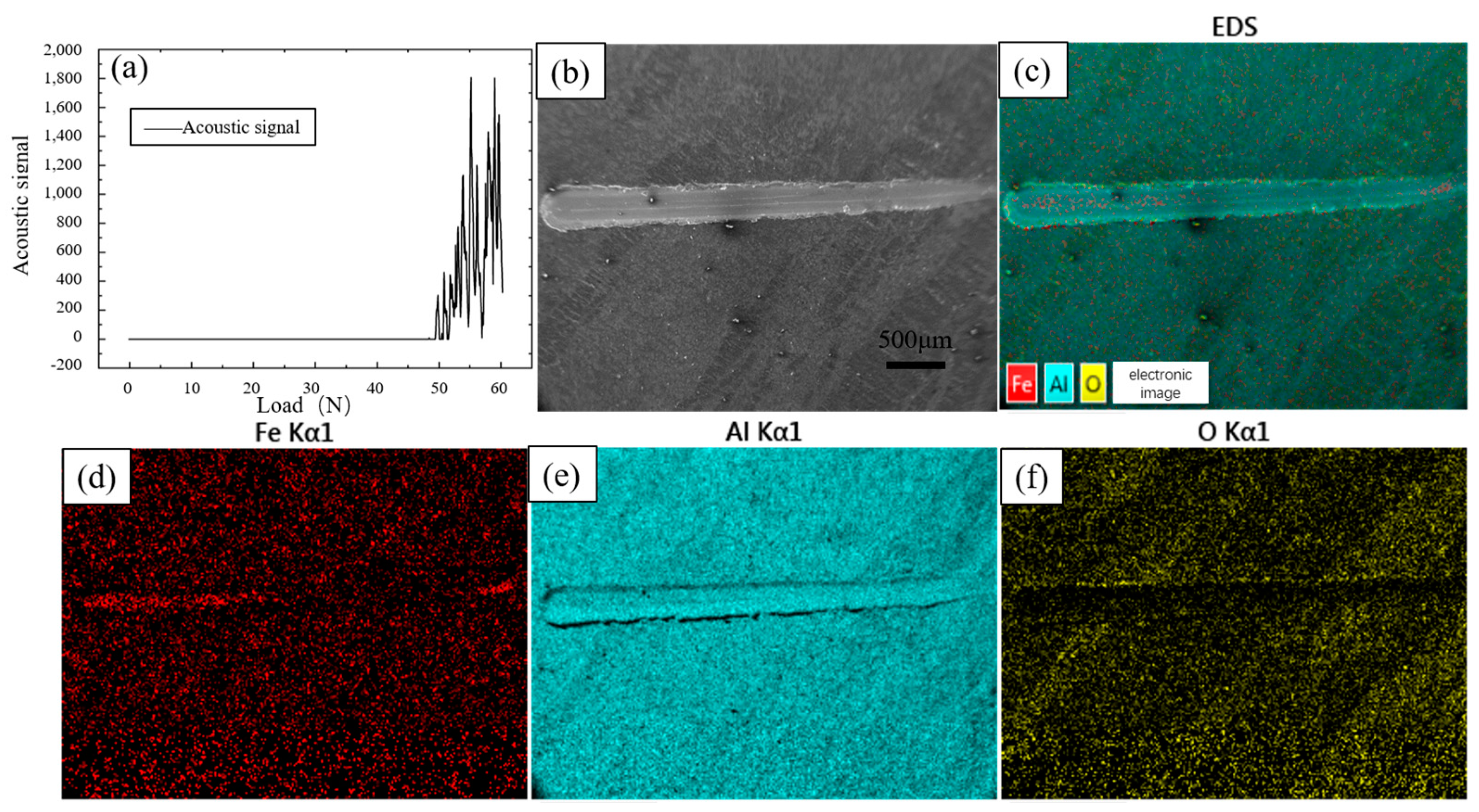
The bonding strength between the coating and the substrate is an important parameter to measure the performance of the coating, which can directly reflect the performance of the coating. Figure 14a shows the results of the coating bonding strength test; the loading load began to appear as a continuous acoustic signal after 49 N, indicating that at this time, the coating began to appear as continuous peeling or cracking, so the coating bonding strength was 49 N. Figure 14b shows the shape of the scratches for this parameter; the scratches are formed by sliding the indenter from the right side to the left side with increasing loading load. From the EDS results, it can be seen that the surface is mainly composed of three elements, Fe, Al, and O. The Al element is uniformly distributed over the whole surface. Since the aluminium-rich layer on the surface is scratched and the inner Fe-Al alloy layer is exposed, the distribution of Fe elements in the first half of the scratch does not differ from that of the surrounding aluminium-rich layer, and the Fe elements increase significantly in the second half. The pure aluminium on the surface is oxidised by oxygen in the air to form an oxide film, so the O element is more evenly distributed.
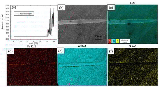
Figure 14.
Scratch test and EDS results of hot-dip aluminium-plated specimens (a) Scratch test results; (b) Scratch surface topography; (c) EDS total results; (d) Fe EDS; (e) Al EDS; (f) O EDS.
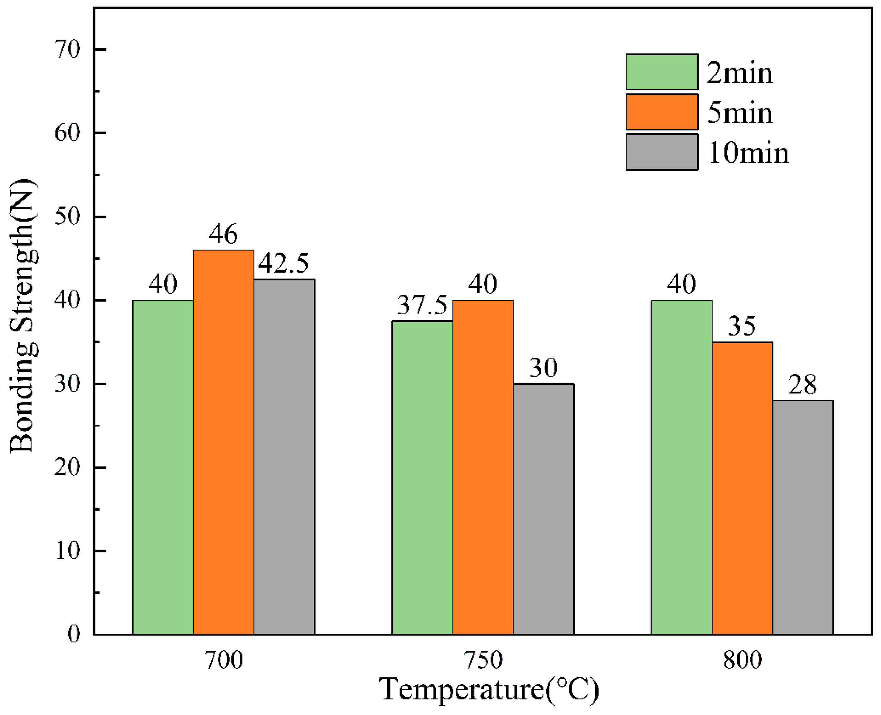
For the testing of acoustic signals in the scratch test, the thesis performed five separate sets of tests on specimens obtained at each process parameter. The thesis took the minimum value of bond strength for each parameter for comparison. The bond strengths obtained for each process parameter were visualised to obtain Figure 15.
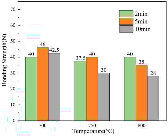
Figure 15.
Bond strength for different process parameters.
Figure 15 shows the results of the bonding strength under different dip plating parameters, which is closely related to the micromorphology of the coating, melt fluidity, etc. During the process of increasing the dip plating temperature, microscopic defects gradually appear on the uniform and dense surface of the coating, and at the same time, the fluidity of the molten aluminium solution increases and the bonding strength of the coating decreases. However, the further increase in temperature will lead to the acceleration of the diffusion of Fe and Al atoms, and the bonding strength of the coating will increase. Therefore, when the dip-plating time is short (2 min), the bonding strength of the coating decreases first and then increases. When the dip-plating time is more than 2 min, the interatomic diffusion will gradually stabilise, the increase in microscopic defects makes the densification of the coating worse, and the bonding strength of the coating will continue to decrease. The longer the dip plating time, the more fully the atoms diffuse, the denser the organisation of the Fe-Al layer will be, and the bonding strength of the coating will increase. At the same time, it will be accompanied by an increase in oxidation inclusions, and the organisation will become loose. When the dip plating temperature is less than 750 °C, the bonding strength first increases and then decreases, and the bonding strength of the coating continues to decrease when the dip plating temperature increases. To ensure that the subsequent anodic oxidation generated by the aluminium hydrogen barrier coating is well matched with the substrate, the hot-dip aluminium layer should have a sufficient thickness, good strength, uniform morphology, and a relatively flat interface. The steel substrate at a dip coating temperature of 700 °C, dip coating time of 5 min obtained after the coating interface is good, the thickness is moderate, the bonding strength of 49 N, the best overall performance.
4. Conclusions
The coating organisation of X80 steel after dip-plating with rare earth oxides La2O3 and Ce2O3 in molten aluminium solution was analysed, and the effects of dip-plating time and dip-plating temperature on the morphology, thickness, and bonding strength of the layer in the hot-dip aluminium-plating process were investigated, and the composition of the physical phases was analysed. The conclusions are summarised as follows:
- (1).
- The coating after hot-dip aluminium plating consists of an aluminium-rich layer on the outside and a Fe-Al alloy layer on the inside, with the aluminium-rich layer uniformly distributed on the surface of the white needle-like FeAl3 phase and the iron–aluminium alloy layer mainly consisting of the serrated Fe2Al5 phase and a small amount of FeAl3 phase at the junction with the aluminium-rich layer.
- (2).
- With an increase in dip plating temperature, the surface FeAl3 phase increases and then decreases. The fluidity of the aluminium solution increases, and the thickness of the aluminium-rich layer decreases while causing defects such as leakage and pinholes. At the same time, the increase in temperature leads to accelerated diffusion of Fe and Al atoms, and the thickness of the intermediate alloy layer increases.
- (3).
- With the extension of the dip-plating time, the size and quantity of the FeAl3 phase on the surface decrease, and the surface oxidation, cavities, and other defects increase, but the thickness of the aluminium-rich layer does not change much. The Fe2Al5 phase grows to the steel matrix in a tooth-like manner, the thickness of the Fe-Al alloy layer increases, and the demarcation line between the Fe-Al alloy layer and the aluminium-rich layer is more and more obvious and straight.
- (4).
- With an increase in the addition of rare earth oxides, the size of the FeAl3 phase on the surface decreases and then increases, and the FeAl3 layer shows a tendency to thicken and then thin, and the aluminium-rich layer gradually thickens. At first, the Al-rich layer and the alloy layer became smooth and flat, and the morphology was better when the addition amount of rare earth oxides was 0.5%, and with the further increase in the addition amount, the defects such as holes and looseness in the coating layer increased significantly.
- (5).
- The bonding strength of the coating is closely related to its microscopic morphology and melt fluidity. At different dip plating temperatures and dip plating times, the bonding strength of the coatings showed a continuous decrease or an increase followed by a decrease. The steel substrate at a dip coating temperature of 700 °C, dip coating time of 5 min obtained after the coating interface is good, the thickness is moderate, the bonding strength of 49 N, the best overall performance.
Author Contributions
Conceptualisation, B.W. and X.S.; methodology, B.W. and X.S.; validation, X.S. and C.Z.; formal analysis, X.S. and C.Z.; data curation, X.S. and C.Z.; writing—original draft preparation; X.S. and C.Z.; writing—review and editing, L.L. and C.Z.; visualisation, C.Z. and E.L.; supervision, H.G., L.Y., and J.Y.; project administration, J.M.; funding acquisition, J.M. All authors have read and agreed to the published version of the manuscript.
Funding
This work was supported by the National Key R&D Program of China [2021YFB4001503].
Institutional Review Board Statement
Not applicable.
Informed Consent Statement
Not applicable.
Data Availability Statement
The raw/processed data required to reproduce these findings cannot be shared at this time due to legal or ethical reasons.
Conflicts of Interest
The authors declare no conflicts of interest.
References
- Tian, X.; Pei, J.J. Study progress on the pipeline transportation safety of hydrogen-blended natural gas. Heliyon 2023, 9, e21454. [Google Scholar] [CrossRef] [PubMed]
- Ohaeri, E.; Eduok, U.; Szpunar, J. Hydrogen related degradation in pipeline steel: A review. Int. J. Hydrogen Energy 2018, 43, 14584–14617. [Google Scholar] [CrossRef]
- Wang, T.S.; Pu, J.; Bo, C.; Jian, L. Sol–gel prepared Al2O3 coatings for the application as tritium permeation barrier. Fusion Eng. Des. 2010, 85, 1068–1072. [Google Scholar] [CrossRef]
- Wang, L.; Yang, J.J.; Liang, C.H.; Feng, Y.J.; Jin, W.; Cao, J.L.; Wang, X.Y.; Feng, K.M.; Kleyn, A.W.; Liu, N. Preparation and properties of improved Al2O3 based MOD coatings as tritium permeation barrier. Fusion Eng. Des. 2019, 143, 233–239. [Google Scholar] [CrossRef]
- Yang, F.L.; Xiang, X.; Lu, G.D.; Zhang, G.K.; Tang, T.; Shi, Y.; Wang, X.L. Tritium permeation characterization of Al2O3/FeAl coatings as tritium permeation barriers on 321 type stainless steel containers. J. Nucl. Mater. 2016, 478, 144–148. [Google Scholar] [CrossRef]
- Zhang, G.K.; Wang, X.L.; Xiong, Y.F.; Shi, Y.; Song, J.F.; Luo, D.L. Mechanism for adsorption, dissociation and diffusion of hydrogen in hydrogen permeation barrier of α-Al2O3: A density functional theory study. Int. J. Hydrogen Energy 2012, 38, 1157–1165. [Google Scholar] [CrossRef]
- Abro, M.A.; Hahn, J.; Lee, D.B. High Temperature Oxidation of Hot-Dip Aluminized T92 Steels. Met. Mater. Int. 2018, 24, 507–515. [Google Scholar] [CrossRef]
- Zhang, J.D.; Yin, Y.S.; Li, J.; Zhang, H. Fabrication and properties of Fe3Al–Al2O3 graded coatings. J. Mater. Process. Technol. 2003, 134, 206–209. [Google Scholar] [CrossRef]
- Huang, J.; Xie, H.; Luo, L.-M.; Zan, X.; Liu, D.-G.; Wu, Y.-C. Preparation and properties of FeAl/Al2O3 composite tritium permeation barrier coating on surface of 316L stainless steel. Surf. Coat. Technol. 2020, 3831, 125282. [Google Scholar] [CrossRef]
- Han, S.L.; Li, H.L.; Wang, S.M.; Jiang, L.J.; Liu, X.P. Influence of silicon on hot-dip aluminizing process and subsequent oxidation for preparing hydrogen/tritium permeation barrier. Int. J. Hydrogen Energy 2010, 35, 2689–2693. [Google Scholar] [CrossRef]
- He, Y.F.; Guo, E.K.; Zhong, F.; Fu, B.W.; Cai, G.-X.; Zhang, D.X.; Jiang, C.Z.; Ren, F. A novel method for preparing α-Al2O3 (Cr2O3)/Fe–Al composite coating with high hydrogen isotopes permeation resistance. Ceram. Int. 2024, 50, 20367–20375. [Google Scholar] [CrossRef]
- Wang, B.Y.; Sun, X.Y.; Liu, E.Y.; Liu, L.; Ma, W.J.; Shi, Y.-Z.; Huang, P.; Luo, Y. Preparation and Hydrogen Barrier Property of FexAly/Al/Al2O3 Composite Coating on X80 Steel Surface. Met. Mater. Int. 2024, 30, 77–78. [Google Scholar] [CrossRef]
- Liu, J.G.; Bi, H.S.; Zhang, Q.S.; Liu, S.Q.; Li, H.W.; Cui, G. Design, fabrication, and hydrogen blocking performance of alumina/zirconia functional gradient coatings. Ceram. Int. 2024. [Google Scholar] [CrossRef]
- Eggeler, G.; Vogel, H.; Friedrich, J.; Kaesche, H. Zielpräparation zum transmissionselektronenmikroskopischen Nachweis der Phase Al3Fe (θ-Phase) auf tauchaluminiertem, niedriglegiertem Stahl/Target Preparation for the Transmission Electron Microscopic identification of the Al3Fe (θ-Phase) in Hot-Dip Aluminised Low Alloyed Steel. Pract. Metallogr. 1985, 22, 163–170. [Google Scholar]
- Xiang, X.; Yang, F.L.; Zhang, G.K.; Wang, X.L. Effect of Steel Substrates on the Formation and Deuterium Permeation Resistance of Aluminide Coatings. Coatings 2019, 9, 95. [Google Scholar] [CrossRef]


Disclaimer/Publisher’s Note: The statements, opinions and data contained in all publications are solely those of the individual author(s) and contributor(s) and not of MDPI and/or the editor(s). MDPI and/or the editor(s) disclaim responsibility for any injury to people or property resulting from any ideas, methods, instructions or products referred to in the content. |
© 2024 by the authors. Licensee MDPI, Basel, Switzerland. This article is an open access article distributed under the terms and conditions of the Creative Commons Attribution (CC BY) license (https://creativecommons.org/licenses/by/4.0/).