Abstract
Cylinder liners, which are an vital part of marine diesel engines, are prone to damage owing to the pool working conditions of reciprocating friction and electrochemical corrosion. As a burgeoning manufacturing technology, laser cladding has a prospective application on repairing and performance enhancement of cylinder liners. The performance of cladding layers on cylinder liners reported by current studies is not satisfactory. The laser cladding, assisted by the steady state magnetic field on the cylinder liner, is an effectual method to cover the shortage. However, there are few studies about that. In this study, single-track Inconel 625 cladding layers were carried out on a cylinder liner, assisted by a steady-state magnetic field. The effects of the magnetic field intensity and direction on the geometrical characteristics (width, height, penetration, and dilution ratio), microstructure, phase composition, microhardness, wear resistance, and corrosion resistance were investigated. According to the results obtained, adding a magnetic field with a small magnetic field intensity can significantly enhance the flatness, hardness, friction, wear resistance, and corrosion resistance of the cladding layer. Applying a magnetic field in the horizontal direction was conducive to improving the corrosion resistance of the sample. With the application of a vertical magnetic field, the microhardness increased, and wear resistance, as well as the flatness of the cladding layer, were improved.
1. Introduction
The cylinder liner is a vital part of the diesel engine, which is an important piece of power equipment, but its working environment is very harsh [1,2,3]. The common failure forms of cylinder liners include wear and corrosion. The wear of the cylinder liner is caused by a combination of physical, chemical, and mechanical factors, and can be divided into abrasive wear, corrosion wear, and adhesive corrosion [4,5]. The corrosion forms of cylinder liners mainly include oxygen absorption corrosion, hydrogen evolution corrosion, and oxygen concentration corrosion [6,7,8]. Premature damage and scrapping of cylinder liners will lead to a waste of resources, so repairing cylinder liners is significant. Common repairing methods of cylinder liners include welding, plating, thermal spray, laser cladding technology, etc. However, parts repaired by welding technology are prone to thermal stress and deformation, with low bonding strength and limited coating thickness [9,10]. For the plating technology, the pretreatment process of workpiece surface is complex, tedious, and has a high cost. In addition, insufficient pretreatment or mistakes during operation may lead to rapid loss of coating and short service life after repairing. Thermal spraying technology makes the workpiece prone to porosity and oxide inclusion. Sometimes, the hardness and impact performance are unsatisfactory, which means the coating is easy to peel off [11]. Compared to the traditional repairing technology, laser cladding technology is a cost-effective way to significantly improve the surface properties of materials, such as wear, corrosion, heat, oxidation, and fatigue resistance. During the laser cladding process, a laser beam is used to melt a powder material onto a thin layer of the substrate surface. The melted powder material then quickly solidifies to form a surface cladding layer. This process results in a layer with a low dilution rate and excellent bonding properties with the substrate. [12]. Therefore, the use of laser cladding to repair cylinder liner has become more popular lately. This method has gained attention due to its effectiveness.
The laser cladding processing is highly affected by the technological conditions. The thermal stress and phase transition stress caused by the large temperature gradient easily cause cracks. Cracks not only reduce coating’s performance, but also shorten its service life, which is one of the important reasons hindering the popularization of laser cladding technology. Additionally, the coating’s surface is uneven and fluctuates after laser cladding, which needs machining treatment. To solve the problems existing during laser processing, auxiliary treatment by external fields, such as the thermal, electromagnetic, and vibration fields, is a promising method [13,14,15]. The external energy field is combined with a thermal energy field provided by a laser to realize the regulation of heat transfer or mass transfer behavior of the molten pool. In particular, laser cladding with steady-state magnetic field assistance has the advantages of simple equipment, multiple control methods, and good control effects. The solidification of the molten pool and grain growth can be controlled, owing to the existence of the electromagnetic braking effect and thermo-magnetofluid effect. Some scholars have studied the steady-state magnetic field-assisted laser cladding, mainly focusing on the flow of the molten pool, composition distribution, and microstructure. M. Bachmann et al. discovered that the steady-state magnetic field can be used to generate induced a Lorentz force to change the shape of the coating in the laser manufacturing process [16,17]. O. Velde et al. used numerical simulation methods to study the effects of static magnetic fields on convection during metal surface growth, and found that static magnetic fields can control eddy currents and improve crystal quality [18]. C. Lee et al. used static stabilizing magnetic fields to suppress the flow on the upper surface of the pool during laser cladding, thus slowing the flow of molten pool, effectively reducing splashing and improving the surface quality of the cladding layer [19]. Q. Kang et al. found that magnetic fields have a significant influence on the defects and properties of laser cladding layers, which could improve element distribution and reduce crack sensitivity [20]. They also found the magnetic field generated a magnetostriction that reduces the elastic modulus, which can improve the cracking and wear resistance [21]. L. Wang et al. focused on the influence of a static magnetic field on the molten pool surface and carried out the cladding experiment, The result pointed out that the resistance generated by a Lorentz force slowed down the flow velocity of the fluid, thus making the molten pool surface smoother due to the effect of magnetic field [22]. T. Hu et al. established a two-dimensional transient cladding model using numerical simulation. It has been found that adding a stable magnetic field in the molten pool can effectively suppress its internal convection [23]. J. Yao et al. conducted a preliminary study using a numerical simulation method, but the mechanism of how a steady-state magnetic field suppressed the surface ripple was not clear. Therefore, they established a two-dimensional transient model of steady-state magnetic field-assisted laser cladding for simulation. It turned out that the steady-state magnetic field intensity interacted with the internal temperature field, flow field, and cladding surface topography and then reduced the dragging force of the WC particles [24].
Therefore, during the laser cladding process, the occurrence of defects such as cracks, pores, and segregation can be reduced by assisting a steady-state magnetic field, which changes the convective state and crystallization characteristics of the molten pool, which promotes the forming quality of the cladding layer. Until now, few studies have been conducted on the auxiliary effects of stable magnetic fields on the distribution of elements in Inconel 625 cladding layers on cylinder liners, and a large number of experiments guided by theoretical models are lacking. In this paper, a steady-state magnetic field was used to reduce the cracks, smooth the surface, and improve the quality of the cladding layer to improve the surface quality of the cylinder liner.
2. Materials and Methods
2.1. Materials and Experimental Set-Up
Inconel 625 powder, which was produced by Hoganas (Ath, Belgium), was selected as the cladding powder, aiming to strengthen the damaged parts of cylinder liner with its high temperature corrosion, oxidation, and excellent wear resistance [25]. It has a particle size range of 45–150 μm. Grey cast iron HT300, which is a commonly used material for the cylinder liners of marine diesel engines, was used for the substrate with a size of 100 mm × 50 mm × 5 mm and surface roughness of 3.6 μm. Table 1 displays the chemical compositions of both the cladding powder and the substrate materials.

Table 1.
Chemical composition of Inconel625 and HT300.
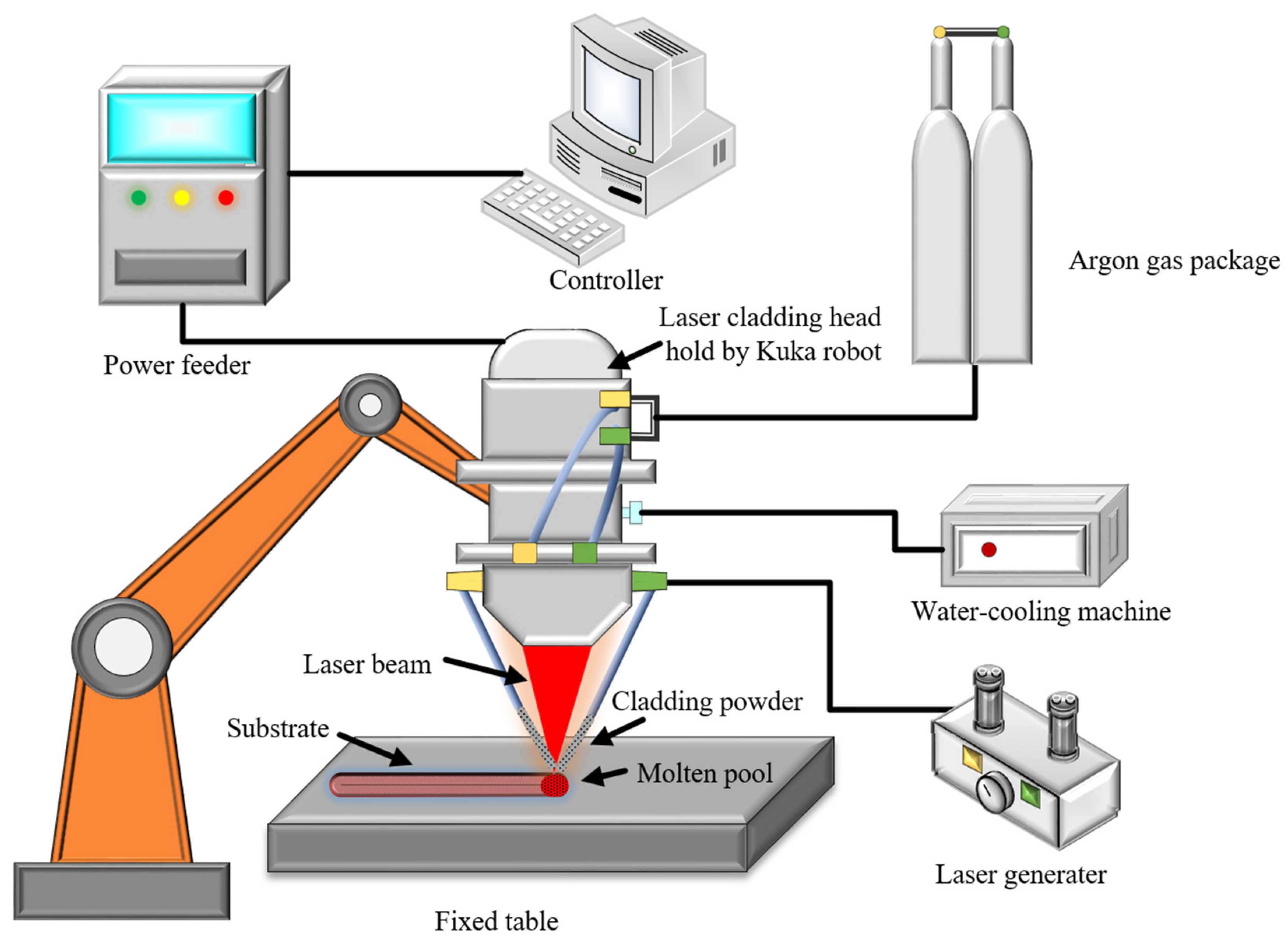
As shown in Figure 1, a laser cladding system was used in this study, including a laser generator (LDF 4000–100, Laserline, Mulheim-Karlich, Germany), a coaxial laser cladding head (YC52, Precitec, Rotenfels, Germany), a six-axis industrial robot (ZH 30/60III, Kuka, Augsburg, Germany), and a gas coaxial powder feeder (RC-PGF-D, Raycham, Anshan, China), as well as a water cooler, air compressor, and other auxiliary equipment.
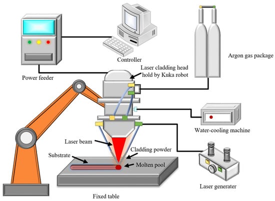
Figure 1.
Schematic diagram of laser cladding system.
2.2. Design of Steady-State Magnetic Field and Parameters
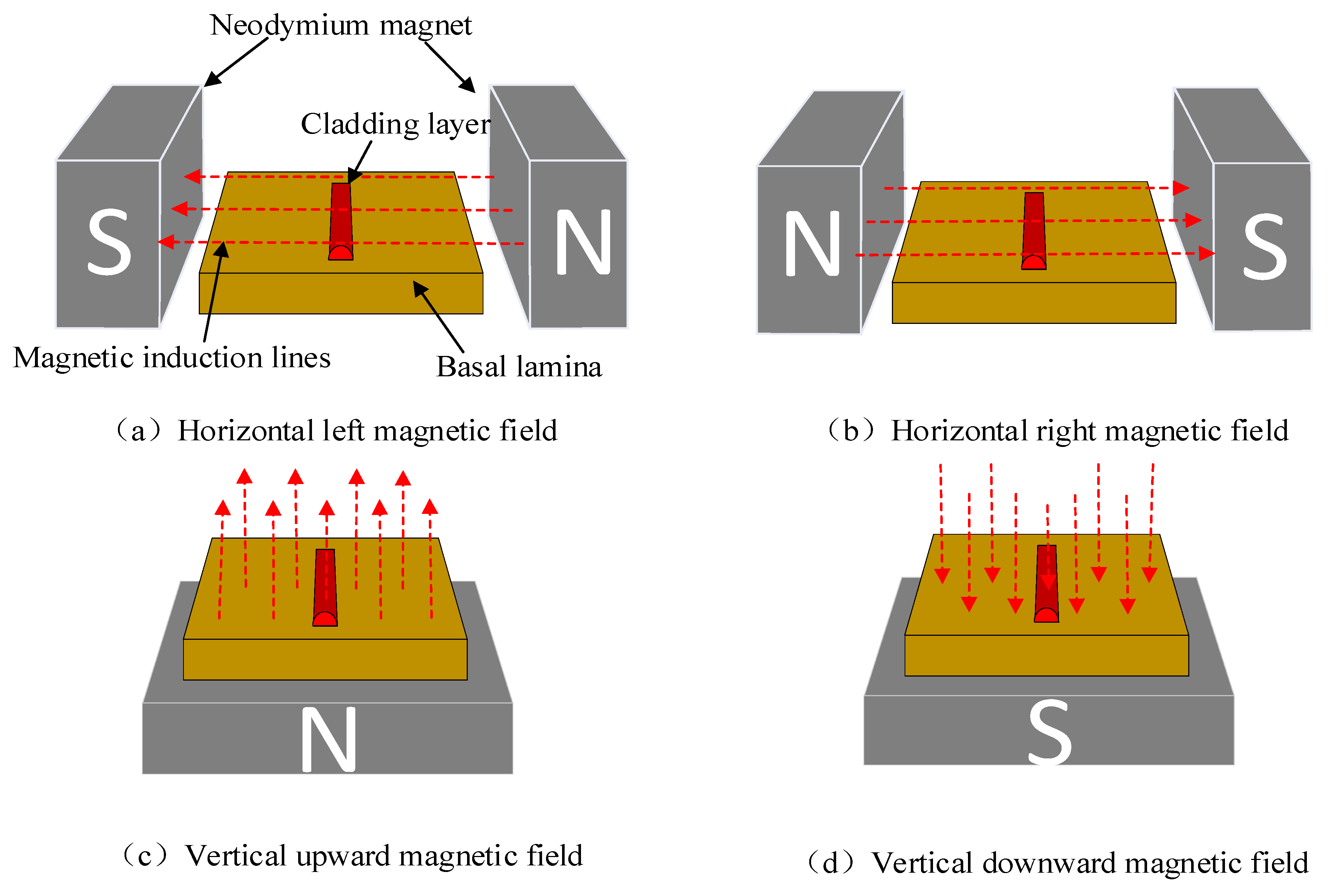
The steady-state magnetic field of this experiment was provided by an NdFeb permanent magnet with a size of 100 mm × 100 mm × 50 mm. Magnetic field intensity and direction were used as experimental factors. The magnetic field intensity was adjusted by changing the distance between the magnets. As displayed in Figure 2, the magnetic field directions, including the horizontal left (L), horizontal right (R), vertical upward (U), and vertical down (D), were determined by the relative location between the magnets and molten pool. The laser cladding parameters, which can create the laser cladding layer with a uniform surface morphology and strong matrix bonding, were determined after long-term research and experimental comparison. The specific experimental parameters are shown in Table 2. In the laser cladding process, 99.99% pure Argon gas was used as both the carrier and shielding gas with flow rates of 400 L/h and 600 L/h, respectively. Under the conditions of different magnetic field intensity and direction, the single-track layers were deposited by laser cladding with the mentioned process parameters.

Figure 2.
Schematic diagram of magnetic field direction.
Table 2.
Experimental parameters.
2.3. Characterization Techniques
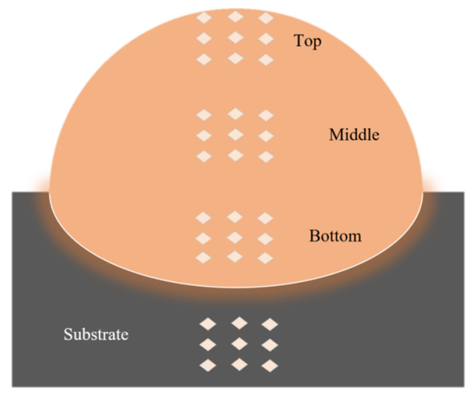
The test specimens were obtained by wire spark erosion, and then mechanically ground and polished. The surfaces were then etched in the saturated oxalic acid solution at 5 V DC. The geometric characteristics of the cladding layer (width, depth, height, and dilution) were obtained. The microstructure of the samples were observed using a metallographic microscope (Leica-DMi8, Leica, Wetzlar, Germany). The dilution adopted in this paper was calculated as the ratio of height to depth of cladding layer. The phase composition of cladding layer was analyzed by Empyrean X-ray diffractometer (Empyrean, Panaco, Malvern, The Netherlands), in which the voltage was 40 kV, the current was 40 mA, the Cu target was used as a cathode in the X-ray diffractometer, and the diffraction angle was 20°–100°. The Vickers microhardness tester (HV-1000, Fangyuan, Jinan, China) was used for measuring the microhardness along the depth direction at the top, middle, and bottom region of the cladding layer, as well as the substrate. As shown in Figure 3, the interval between the measured points of microhardness was 0.1 mm, the load was 1 kg, and the loading time was 15 s. The friction wear testing machine (CETR-UMT, Bruker, Billerica, America) was used to conduct friction wear tests on the substrate and cladding samples, respectively. A tungsten steel ball was used for wear test, the loading force was 50 N, the sliding distance was 15 mm, and the sliding frequency was 1 Hz. Single samples were rubbed at 23 °C for 20 min. The samples were weighed and recorded before and after wear tests using electronic balance (FA1004N, Qinghai, Shanghai, China) to calculate the abrasion loss. A three-electrode electrochemical corrosion system (CHR6601, Huachen, Shanghai, China) was used for electrochemical corrosion test where the solvent was NaCl solution with a mass fraction of 3.5%. The measurement range was −0.9 V~0.2 V. The sampling rate was 0.01 V/s. Corrosion and abrasion tests were performed multiple times to ensure the credibility of the test results.

Figure 3.
Schematic diagram of the Vickers hardness test.
3. Results and Discussion
3.1. Geometrical Characteristics
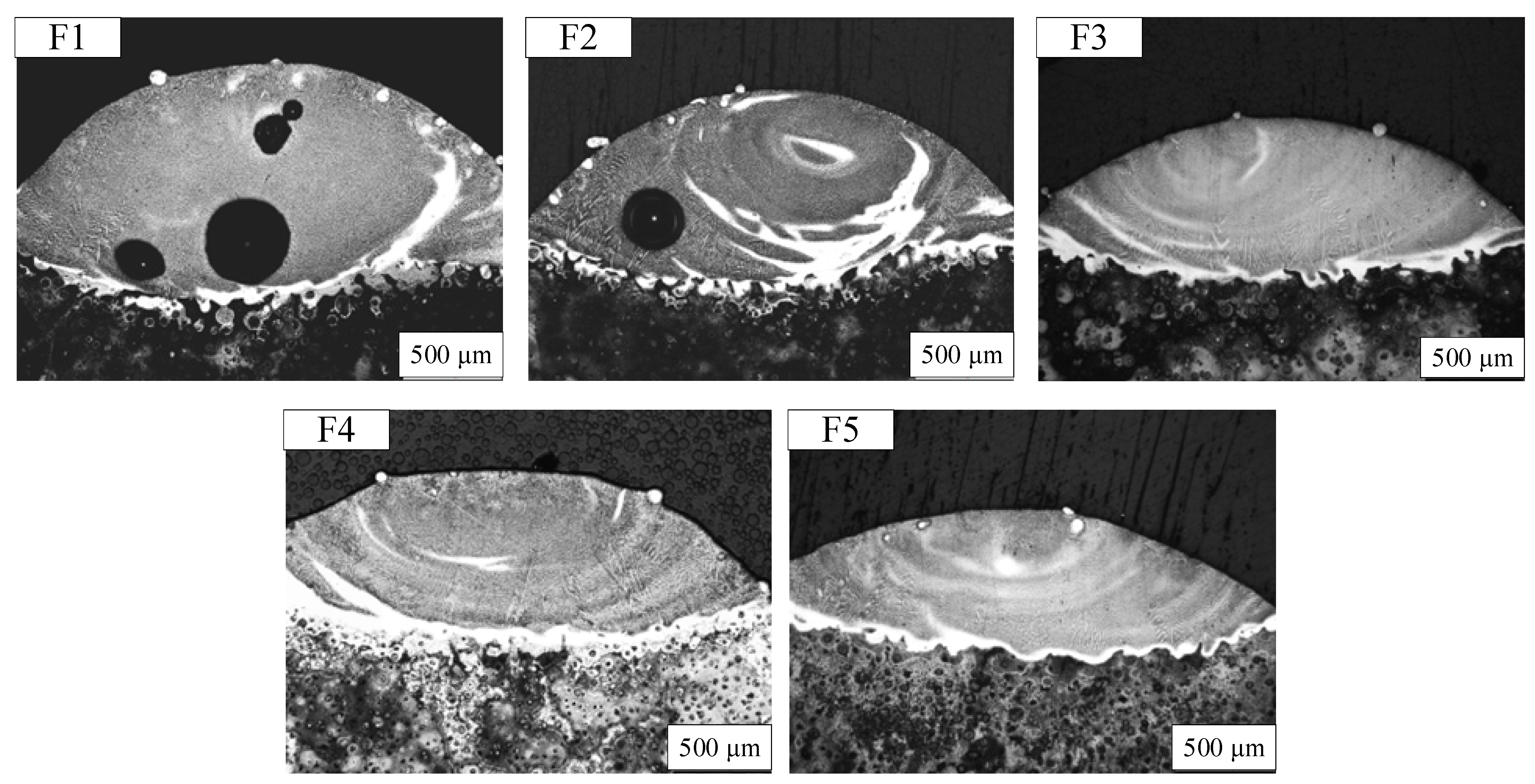
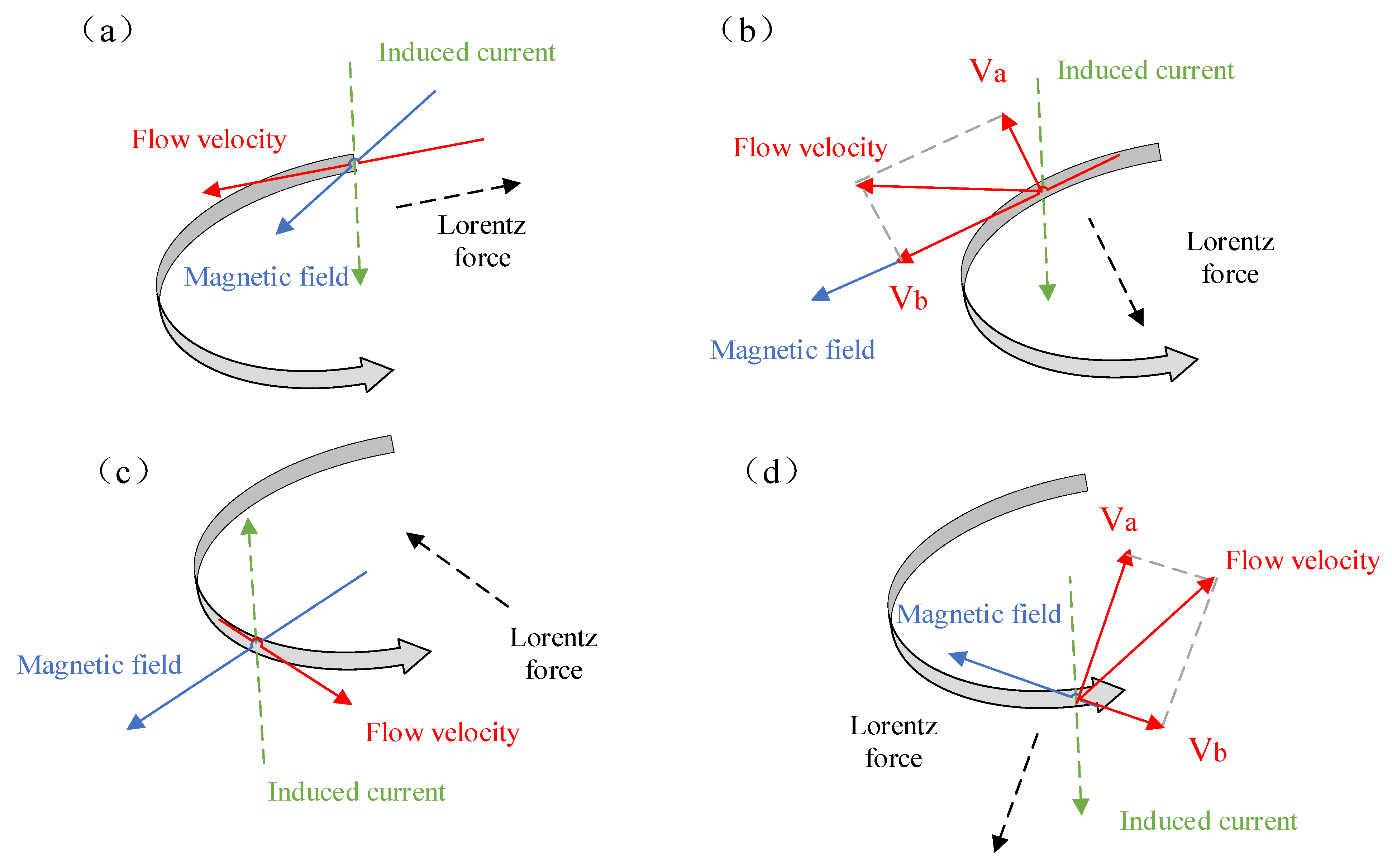
As displayed in Figure 4 and Table 3, from the perspective of the macro profile, the molten pool without the addition of a steady-state magnetic field presented a plump oval shape, and the molten pool contained many round pores. The macromorphology of the molten pool changed obviously when a higher intensity steady-state magnetic field was applied. Put another way, the overall macro profile of the cladding layer will be gradually flattened when a higher steady-state magnetic field is applied. This is the result of the interactions between hydrodynamics and electrodynamics. Figure 5 shows the mechanism of the inhibiting effect for the convection of the molten pool during the laser cladding assisted by the steady-state magnetic field process, where the circle line represents the convection of molten pool, which is determined by the temperature field and v is the flow velocity of the molten pool.

Figure 4.
The morphology of the cladding layer under magnetic field intensity of (F1) 0 mT, (F2) 50 mT, (F3) 100 mT, (F4) 150 mT, and (F5) 200 mT.
Table 3.
The cross-sectional size and dilution rate data of single-channel cladding layer under various applied steady-state magnetic field strengths.
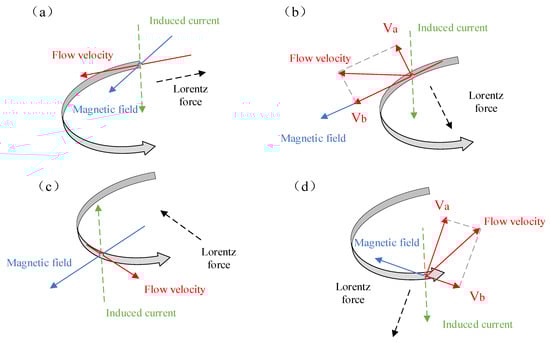
Figure 5.
Schematic diagram of the mechanism of magnetic field inhibiting convection: (a) B ⟂ V, (b) θ < 90°, (c) B ⟂ V, (d) θ > 90°.
When the molten metal moves in the molten pool along the vertical direction of the magnetic field, an induced current will be generated. Such a moving material with an electric charge will experience the opposite Lorentz force () in a magnetic field. Therefore, when there is a magnetic field perpendicular to the laser cladding direction, a Lorentz force component, which is offset with the original molten pool motion direction, will appear, which results in a reduction in the convection velocity and the generation of the electromagnetic braking effect [26,27,28,29]. Under the condition of the steady-state magnetic field, the induced current (Jw) can be expressed as , where v is the velocity of fluid and σ is the conductivity of the solution. The expression of the induced Lorenn magnetic force is , where the induced electromagnetic force is proportional to the square of the intensity of the magnetic induction, and it can be judged that the direction of the induced electromagnetic force is in the opposite direction to the flow direction of the melt, which has the effect of inhibiting the convection of the molten pool.
Due to the weakened convection, the high-temperature melt in the upper part of the molten pool cannot flow down to the bottom, which makes a large amount of the high-temperature melt stay in the top part of the molten pool and, as a result, less substrate was melted. Carbon in the substrate reacted with oxygen at high temperatures to produce pores. A lack of magnetic field assistance led to more substrate, which was melted with the high content of carbon elements, and it easily reacts to produce pores under high temperature conditions. So, the accumulated high-temperature melt in the top part of the molten pool transfers heat to the horizontal direction, which contributes to the increase in the width and reduction in pore defects.
Figure 6 and Table 4 present the morphology and size data of molten pool under different magnetic field directions. It is visible in Figure 6 that, when the horizontal magnetic field was applied, the height and width were higher, but the depth and dilution rate of the molten pool were lower. However, the external stable magnetic field has a limited effect on the width, which mainly depends on the laser cladding process parameters.
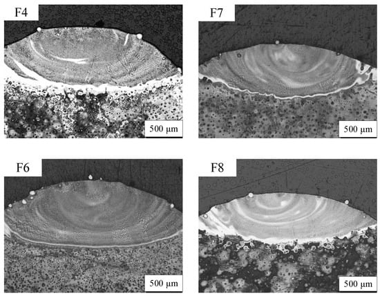
Figure 6.
The morphology a of molten pool under magnetic field direction of (F4) left, (F6) right, (F7) upward, and (F8) downward.
Table 4.
The data on the cross-sectional size and dilution rate for a single cladding layer has been obtained under magnetic fields in all directions.
The convective movement in the laser molten pool is the fundamental cause of the concave–convex corrugating on the cladding layer’s surface. The steady-state magnetic field can reduce the velocity of the molten pool surface in the normal direction, thus reducing the elevation of the coating and smoothing the coating’s surface. With an increase in magnetic induction, the surface smoothness is further improved. Therefore, the electromagnetic braking effect of the steady-state magnetic field is a favorable factor for decreasing the surface fluctuation.
3.2. Microstructure
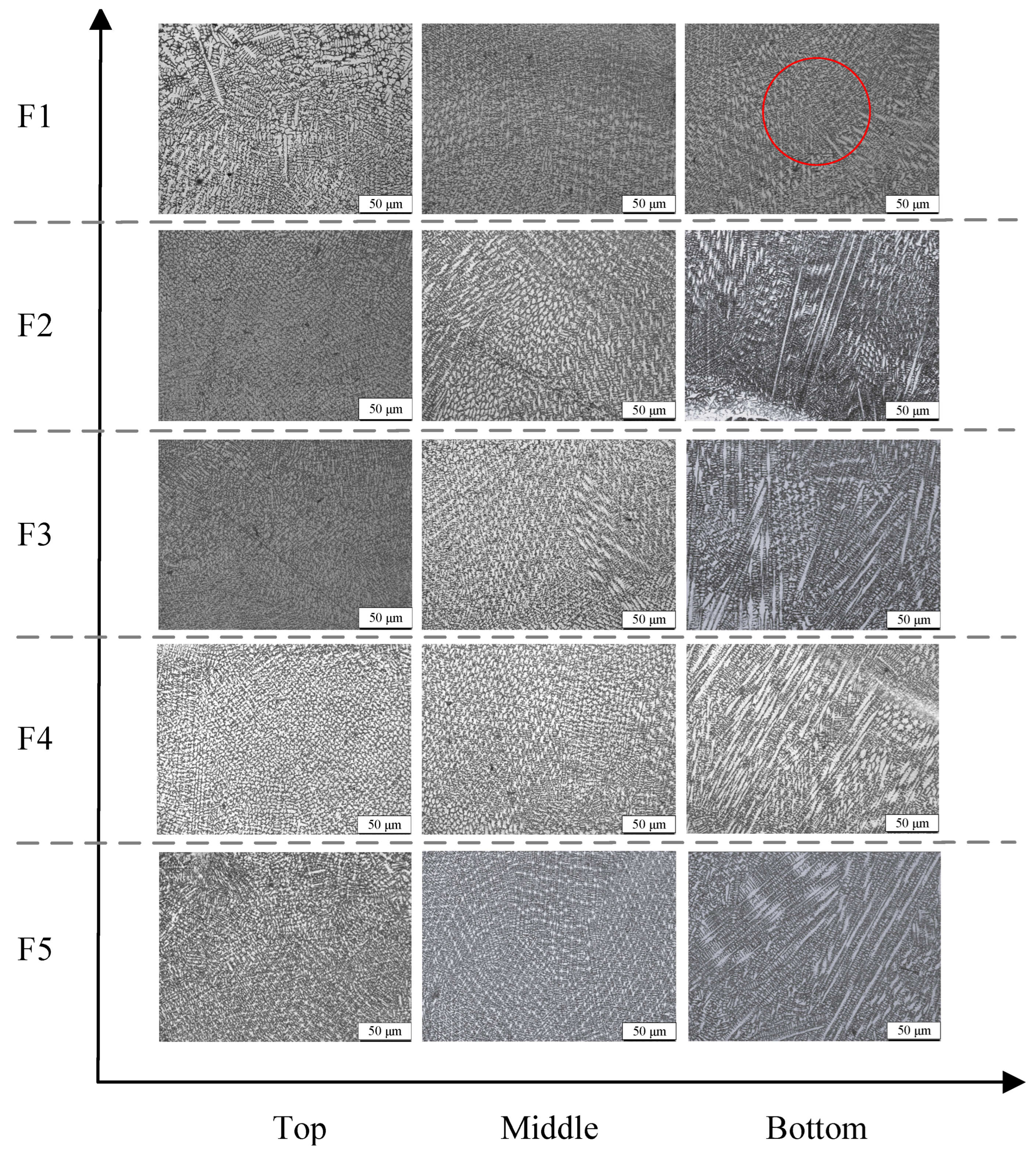
Figure 7 displays the cross-sectional structure of the Inconel 625 cladding layer with different magnetic field intensities. It is visible in Figure 7 that the dendrite growth followed the typical solidification microstructure characteristics of laser cladding; that is, the microstructure mainly changed from planar crystals near the bottom to a cellular and columnar dendritic near the middle, and then to epitaxial crystals near the top along the direction of the cladding height, regardless of whether a steady-state magnetic field was applied. F1 shows the cladding layer without a steady-state magnetic field. The microstructure presented relatively small columnar crystals in the bottom and middle regions of F1, whose crystal growth direction was mainly towards the maximum heat dissipation direction. Since the isotherm was perpendicular to the heat dissipation direction, the dendrite growth direction was perpendicular to the isotherm of this layer. F2 and F3 shows the microstructure of the cladding layers under the steady-state magnetic fields with magnetic field intensities of 50 mT and 100 mT. The columnar dendrites near the bottom were slightly thicker than those without an applied magnetic field. The convection at the bottom interfered with the external transverse steady magnetic field, and changed the heat flow direction of the cladding layer slightly at a small magnetic field intensity. The growth direction of the dendrite was about 70°–80° in the horizontal direction. F4 presents the microstructure of the cladding layer when a 150 mT steady-state magnetic field is added. It can be found that a larger range of strong columnar dendrites with more orientation appeared near the bottom. These dendritic stems were arranged neatly, and the growth direction was about 60°–45° from the horizontal direction. With an increase in the steady-state magnetic field intensity, the electromagnetic braking effect was increasingly stronger, which reduced the velocity of convection. In this case, the primary dendrites grew along the direction of heat flow, but the secondary dendrites were inhibited to a greater extent. In the middle region, there were a large number of dendrites, and many fine equiaxed crystal structures were surrounded between and above each dendrite. F5 is the microstructure with a stable magnetic field intensity increased by 200 mT. Many columnar dendritic crystals with neatly arranged trunks can be found at the bottom and middle. The angle between the growth direction and the horizontal line was reduced to about 45°.
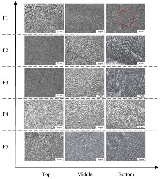
Figure 7.
The microstructure of the molten pool under different magnetic field intensities.
Additionally, compared to the cladding structure without a magnetic field, the dendrites with different directions changed to dense equiatomic structures in the middle and top with an increase in the constant magnetic field intensity. When a low-intensity magnetic field was applied to the solidification of the liquid metal, the temperature gradient at the solidification front decreased with an increased magnetic Taylor number. Simultaneously, the enhancement of the magnetic field intensity increased the induced current in the molten pool, and generated a larger magnetic Taylor number and a smaller temperature gradient, which were conducive to the formation of equiaxed crystals [30]. Therefore, the auxiliary of a stable magnetic field applied during the laser cladding process can reduce the internal energy exchange, the temperature difference of the interface front, and the concentration of the crystallization area of the supercooling degree, and improve the stability of the crystallization front, to promote the creation of numerous equiaxed crystals.
On the other side, under the condition of the steady-state magnetic field, the liquid metal generated a relative flow in the crystallization front, and scoured or fused the formed grains. These broken grain fragments were brought into the molten pool by the convection, and became new nucleation particles, forming a finer crystal structure, promoting the formation of equiaxed crystals, and were conducive to refining the cladding layer structure. Therefore, with an increase in magnetic field intensity, a larger range, denser, and smaller equiaxed crystals ensured excellent performance of the entire cladding layer. Simultaneously, when the constant magnetic field intensity increased, dendrites in different directions were transformed into dense equiatomic crystal structures in the middle and top of the cladding layer. Dendrites also appeared over a wider area, and they were more robust and organized than before.
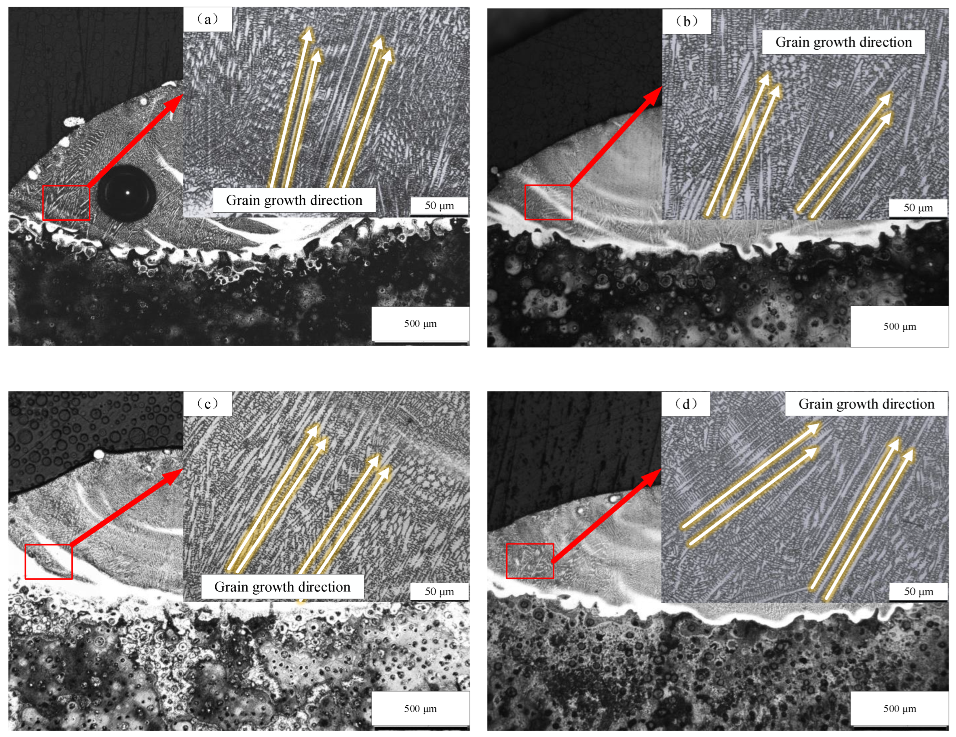
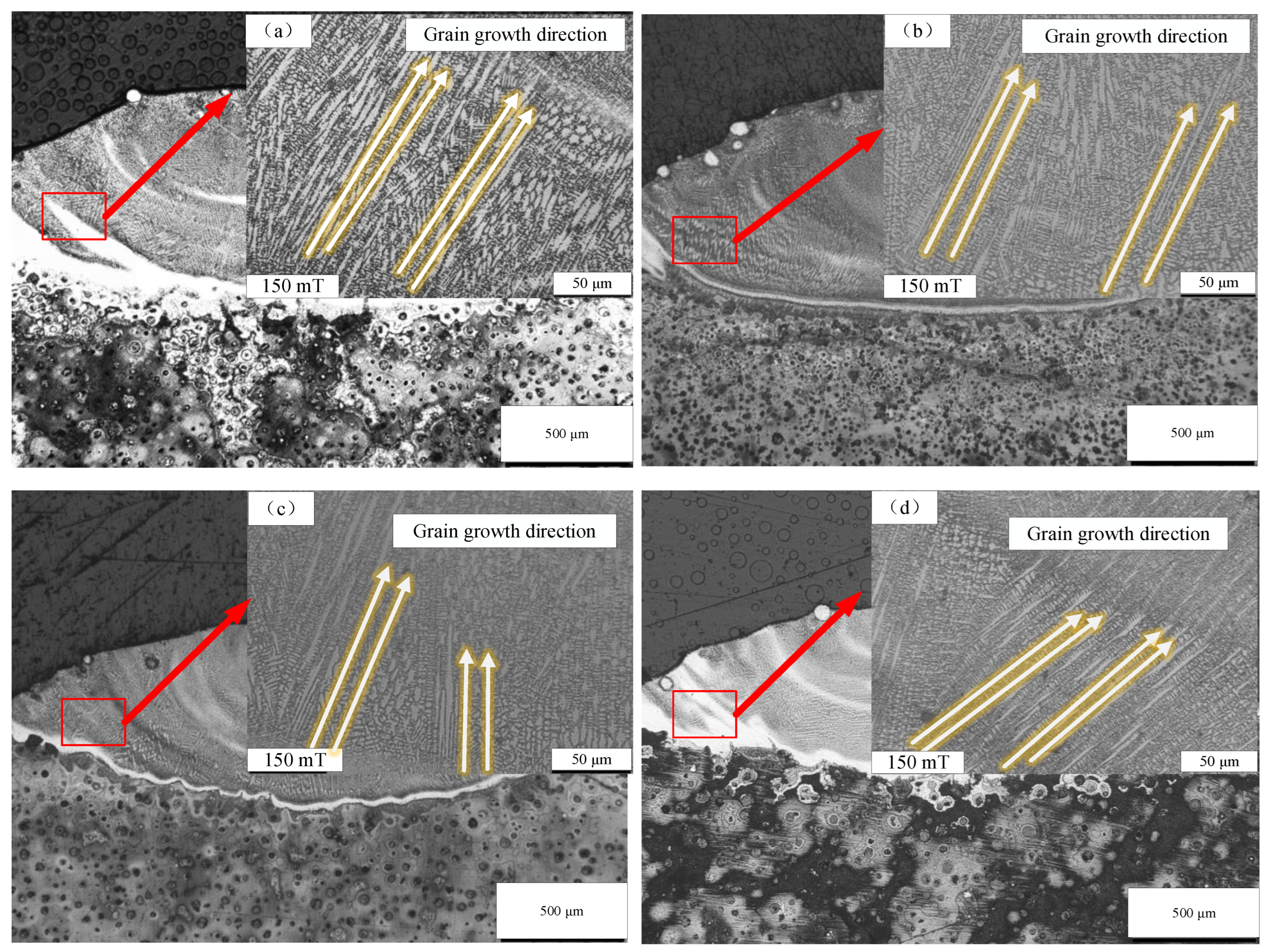
Figure 8 shows the direction of the dendritic growth when different magnetic field intensities are used. As observed in Figure 8, a stable magnetic field led to dendrite coarsening, and its growth direction extended towards the direction of maximum heat dissipation. Since the magnetization of the Inconel 625 nickel–iron alloy in a molten state caused changes in magnetization energy, the crystal contained iron, which is easy to magnetize, and the crystal had the magnetic anisotropy. When the paramagnetic substance was magnetized, the magnetic moment of the molecule was parallel to the applied magnetic field direction, so the magnetized axis was biased to the magnetic field direction. The magnetization Xm of Inconel 625 is 50–100, and its magnetic anisotropy is significant when placed in a magnetic field, so that the axis of magnetic anisotropy is deflected towards the magnetic field direction and tends to be parallel to the magnetic field direction. In the cladding layer, the growth direction of dendritic crystals will change when the steady magnetic field is not applied; that is, when the steady magnetic field is applied horizontally to the left, the dendrites on the right side of the molten pool will be deflected horizontally, and the angle formed between the growth direction and the horizontal direction decreases, leading to a change in the growth mode of dendritic crystals. The influence of a steady magnetic field on dendrite deflection is limited in a complex, convective environment. However, these two factors work together to cause some dendrites to grow along the stable magnetic field direction, and the dendrites show a tendency to grow in that direction. This may be due to the maximum heat dissipation direction of the liquid flow and the horizontal magnetic field. Figure 9 shows the direction of dendritic growth with different directions of magnetic fields with an intensity of 150 mT. It can be seen from Figure 9 that changing the direction of the magnetic field had similar effects on the top and middle regions of the cladding layer. The auxiliary of a steady-state magnetic field made dendritic and cellular crystals stronger and extend towards the direction of maximum heat dissipation. Similarly, compared to the horizontal magnetic field, the vertical magnetic field caused the dendrites to grow at a smaller angle in the vertical direction without any external factors after magnetization; that is, they deflected and tended to grow steadily along the vertical direction.
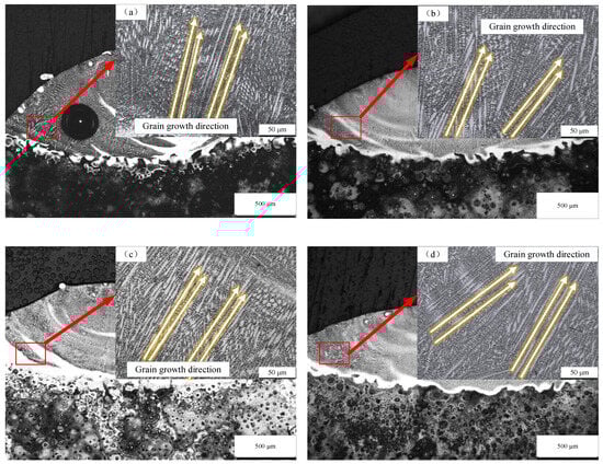
Figure 8.
The direction of dendritic growth under magnetic fields with intensities of (a) 50 mT, (b) 100 mT, (c) 150 mT, (d) 200 mT.
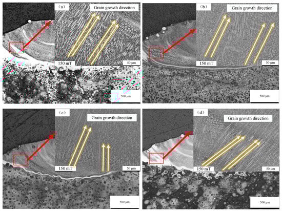
Figure 9.
The direction of dendritic growth with the (a) L, (b) R, (c) U, (d) D directions of the magnetic fields with an intensity of 150 mT.
3.3. XRD Pattern Analysis
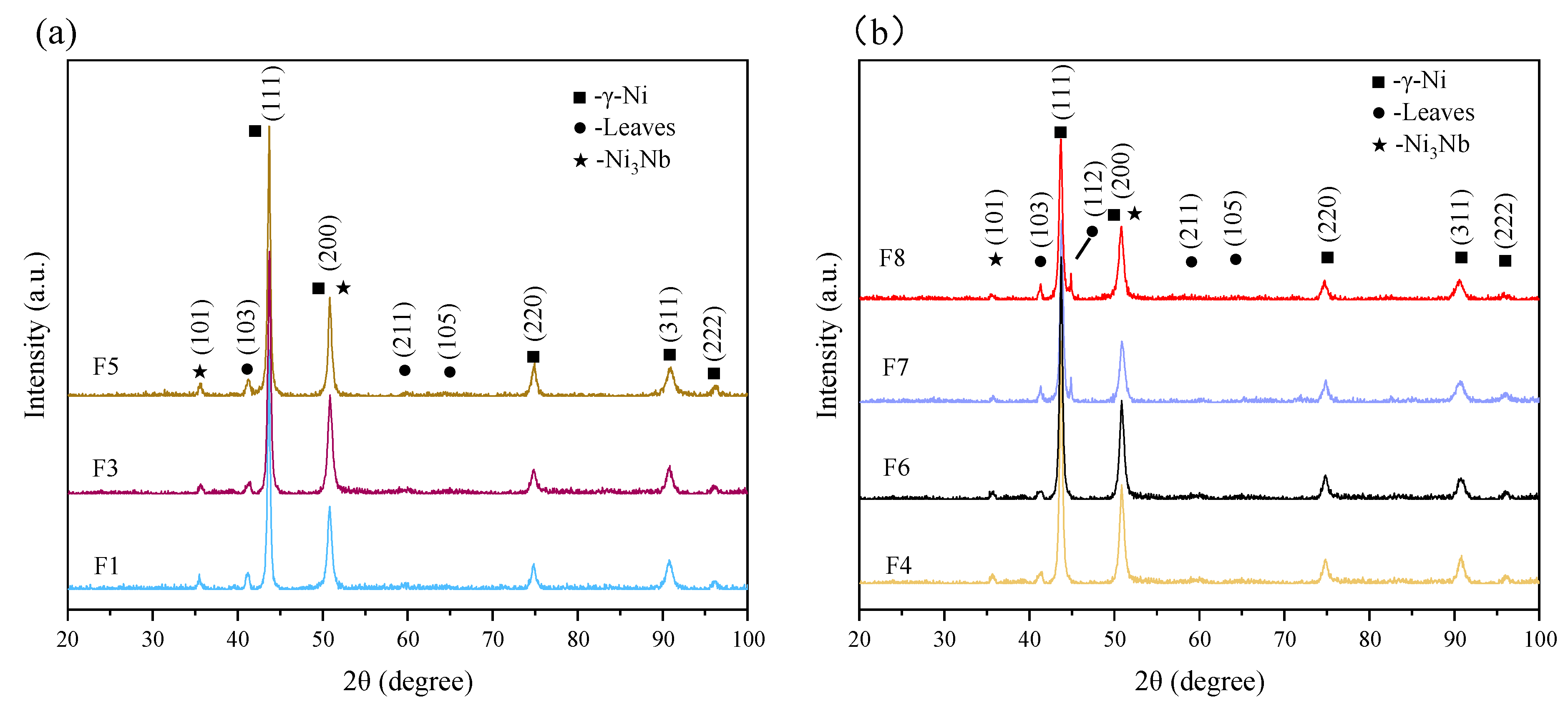
As displayed in Figure 10, the cladding layer phase was composed of the matrix phase of γ-Ni, the Laves phase of Ni2Nb, and the strengthened phase of Ni3Nb, which were all included in the atlas of each experimental group. It is indicated that the composition of the cladding layer phase was not changed. As the steady-state magnetic field intensity increased, the content of γ-Ni increased, and the strengthening phase of Ni3Nb was enhanced. However, the Laves phase of Ni2Nb decreased. This effect caused the molten pool to flatten, and increased the surface heat dissipation area, leading to an increase in the cooling rate of the molten pool surface. Therefore, a decrease in the Laves phase is directly related to an increase in the cooling rate. Figure 10b displays that the change in magnetic field direction not only does not change the phase composition, but also has the same level of influence on the phase content. It can be analyzed from Figure 10b that the steady-state magnetic field added in the horizontal direction had a higher diffraction peak than that of the matrix phase and the strengthened phase added in the vertical direction, while the diffraction peak of the Laves phase was lower. When the steady magnetic field with D direction was applied, the cross-section width of the cladding layer was slightly wider than that of the upward magnetic field, and the height and depth of the molten pool were lower, resulting in better surface heat dissipation performance, and a lower content of the Laves phase between dendrites in the molten pool.
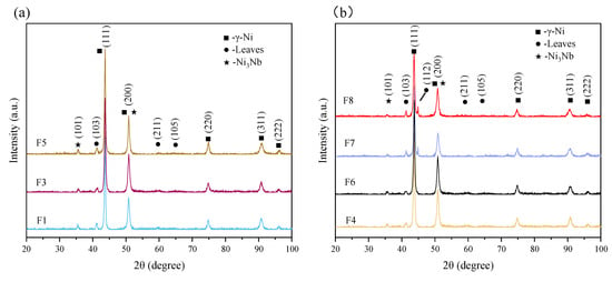
Figure 10.
X-ray diffraction spectra of the cladding layers with different: (a) intensities and (b) magnetic field directions.
Table 5 shows the XRD data of the matrix phase γ-Ni on the (111), (200), and (220) crystal planes. The diffraction peak data presented show that the diffraction peaks of the γ-Ni matrix phase on the two crystal planes (111) and (200) all shifted to low angles, indicating that the lattice constant of the γ-Ni matrix phase solid solution changed with an increase in magnetic induction intensity. The matrix phase γ-Ni solid solution lattice constant α is expressed as:
Table 5.
XRD data of matrix phases gamma-Ni on the (111), (200), and (220) crystal planes.
The lattice constant, half-width, and height of the matrix phase γ-Ni solid solution increased with an increase in magnetic induction intensity. This indicated that the steady-state magnetic field can not only enhance the solid solubility of the matrix phase γ-Ni, but also refine the grain. In liquid metals, atoms lose their valence electrons to form ions, which move randomly. When a magnetic field is applied, the liquid cuts the magnetic field lines and creates a Lorentz force, causing the ions to rotate around them. Due to the differences in the mass and charge of Ni, Fe, Nb, and Cr, their plasma behaves differently in the molten pool, and various solute particles have a relative motion to the matrix phase under the condition of the magnetic field. This motion enhances the diffusion motion of solute particles in the matrix phase, and eventually leads to an increase in the solute elements in the matrix phase -Ni solid solution. The content increase in the γ-Ni solid solution can stabilize the crystal structure. The enhancement effect increases with the strength of the constant magnetic field.
As shown at the bottom of F1 in Figure 7, a reference line with a radius of 50 µm was drawn on the images to obtain the grain size by determining the number of grains crossing the reference line. The results of the grain sizes are shown in Table 6.
Table 6.
Grain size (μm).
As shown in Table 3 and Table 6, after applying a steady-state magnetic field, the grain structure of the entire coating became more refined. This suggests that the thermoelectric magnetofluid effect was the primary factor influencing the solidification process. In the solidification process, the first precipitated solid phase and melt exist at the same time to form a paste zone. The different temperatures between solid phase and liquid phase in the pasting zone will produce a temperature gradient (ΔT) in these two phases, so that the solid/liquid phase has different thermoelectric potential. Generally, the solid/liquid phase is regarded as a closed loop, which generates the thermoelectric potential difference , generating thermal current JTE, and the expression is [31,32,33]
where are the electrical conductivity; are the thermoelectric potential ratio; and are the volume fractions. The thermoelectric force can be expressed by the following formula [31,32,33]:
In the formula, is the thermoelectric force generated by the steady-state magnetic field; B is magnetic induction intensity.
The steady-state magnetic field can produce opposing effects on the solution pool through the electromagnetic braking effect and thermoelectric magnetofluid effect, which promote grain magnetization and dendrite structure fusion. The electromagnetic braking effect can weaken the flow velocity of the fluid, inhibit the formation of equiaxed crystals, and promote the growth of columnar crystals. The thermoelectric magnetic force acting on dendrites by the thermoelectric magnetofluid effect can refine grains [34]. Based on the changes in the macroscopic morphology and microstructure of the coating in this section, it has been observed that a steady-state magnetic field can have an electromagnetic braking effect on the molten pool, which can result in a smoother surface. However, the steady-state magnetic field can also refine the grain structure, which indicates that the steady-state magnetic field also has a thermo-magnetic fluid effect on the molten pool.
3.4. Microhardness
The hardness of a material is an important mechanical property index, which shows the ability of the surface to resist deformation. It is visible in Figure 11 that the hardness of the cladding layer after cladding with the Inconel 625 alloy was above 360 HV, which was much higher than the measured value of 246.3 HV of the matrix gray cast iron. There was a small difference in the hardness between the middle region and the bottom region, but the bottom hardness was slightly lower than that of the middle region, because the middle part of the cladding layer contained significantly more cellular crystal structures, while the bottom was mostly occupied by the dendritic crystal, whose hardness was lower than the cellular crystal. The hardness of the top was slightly higher than that of the rest region, mainly because of the small G/R at the top of the cladding layer, the large undercooling degree, and the equiaxed crystal structure with a smaller grain size. In addition, with increasing magnetic induction intensity, the microhardness distribution value of the cladding layer showed a gradual increase. This indicates that the strength of the magnetic field has a significant impact on the microhardness of the cladding layer, and the thermoelectric magnetofluid effect played a significant role. The existence of the temperature gradient and the potential difference between the solid and liquid phase formed a closed loop circuit that resulted in the creation of induced current on the newly crystallized dendrites. The current generates a Lorentz force under the condition of the magnetic field, and the Lorentz force acts on the dendrites. Combined with the mechanical scour effect of the Marangoni flow on the dendrites, the crystallized dendrites are broken to form a new nucleation, thus improving the nucleation rate and refining the grains that contribute to the increase in microhardness. As can be seen from Figure 11, the top hardness of the cladding layer under any magnetic field direction was slightly higher than that of the middle and bottom of the cladding layer. From the perspective of different magnetic field directions, the hardness of each region of the cladding layer was the highest when the vertical downward steady magnetic field was added, followed by the vertical upward magnetic field direction, while the hardness difference was small when the horizontal magnetic field was added. The grain size of the magnetic field in the vertical direction was smaller than that of the magnetic field added in the horizontal direction, so the experimental results were consistent with the law of the calculated data.
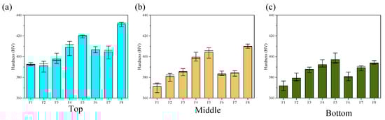
Figure 11.
The microhardness of the cladding layers: (a) top; (b) middle; (c) bottom.
It is visible in Figure 11 that the hardness of the cladding layer top part under any magnetic field direction was slightly higher than the middle and bottom. From the perspective of different magnetic field directions, the hardness of each region of the cladding layer was the highest when the vertical downward steady magnetic field was added, followed by the vertical upward magnetic field direction, while the hardness difference was small when the horizontal magnetic field was applied. The vertical direction resulted in a smaller grain size for the magnetic field compared to the horizontal direction, so the experimental results were consistent with the law of the calculated data.
3.5. Wear Resistance
To obtain better wear performance for marine diesel engine cylinder liners, and to study the influence law of a magnetic field on the friction coefficient and wear weight loss of the cladding layer, the magnetic field intensity and magnetic field direction were changed in this section, and the average data were obtained from three wear tests for each sample, respectively.
It is visible in Figure 12 and Table 7 that the wear loss of substrate was the highest. With an increase in magnetic field intensity, the wear loss of the cladding layer decreased to different degrees. At a magnetic field strength of 200 mT, the cladding layer exhibited the best wear resistance, with a wear mass of approximately 14.4 mg and an average friction coefficient of 0.5902. Compared to the other magnetic field direction, the abrasion loss of the cladding layer fabricated with the R direction presented highest value of 32.4 mg, and the average friction coefficient was 0.72. When the D direction was applied, the abrasion loss was about 16.9 mg, and the average friction coefficient was 0.59, which means the cladding layer presented the optimal wear resistance.
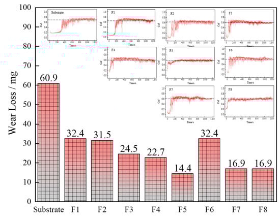
Figure 12.
The wear amount and friction coefficient of the cladding layer.
Table 7.
The abrasion loss and friction coefficient of the cladding layer.
The higher the hardness result, the lower the friction coefficient and the abrasion loss, which means the better the friction performance. This is due to the presence of a hardness difference between the friction pairs, which leads to plastic deformation of the softer material, with more material being adhered and torn in a relative motion, producing more abrasion loss and leading to an increase in the friction coefficient. Reducing this hardness difference by increase the hardness of softer material reduces the friction coefficient and the abrasion loss, resulting in a better friction performance.
Figure 13 displays the morphology of the coatings. It is visible that when no magnetic field was applied, there were mainly two types of wear on the surface of the substrate: abrasive and fatigue wear. The surface of the cladding layer presented an uneven state, and there were a lot of pear grooves, stratified zones, and particulate matter. In addition, under the action of the high uplift caused by the plastic deformation, obviously worn edges can be produced. At the same time, some shallow ploughing and different degrees of spalling, accompanied by severe material transfers and slight cutting, were presented. As shown in F1–F8 of Figure 13, the decrease in the depth of the scratches and the distance between the scratches indicated the positive influence of the magnetic field on the wear resistance of cladding layer. Only a small amount of material fell off the surface, with minimal deformation and scratch depth, at a magnetic field intensity of 200 mT. This is due to the density of equiaxed crystals in the cladding layer, which increased with the magnetic field intensity and resulted in the presence of equiaxed crystal structures, significantly enhancing the overall microhardness of the coating after the magnetic field was applied. In addition, the magnetic field can partially prevent convection during the laser cladding process, and results in a more even distribution of carbide particles. This not only effectively prevented crack propagation, but also enhanced the bonding strength between the carbide particles and the equiaxed matrix. Consequently, the wear resistance of the cladding layer was significantly improved.
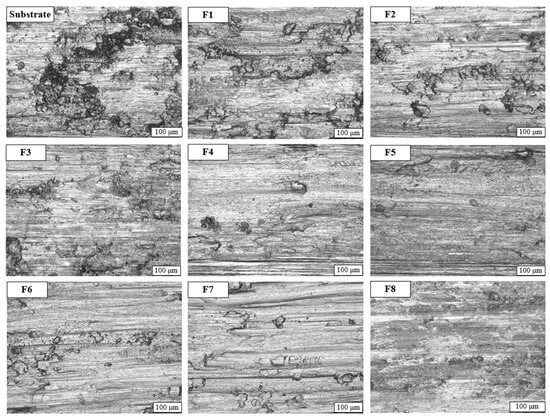
Figure 13.
The surface of cladding layer after the wear test.
From the perspective of the magnetic field direction, as shown in F4 and F6–F8 of Figure 13, debris peeling occurred in the samples applied in the U direction, while surface peeling and the furrow phenomenon were relatively alleviated in the samples applied in the D direction, accompanied by some fine and uniform scratches. However, the samples applied in the L and R directions presented ploughing surfaces. Because the wear performance was related to the hardness of the cladding layer, the hardness was the highest when the downward vertical magnetic field was applied, which showed that the sample had better friction and wear performance.
3.6. Corrosion Resistance Test
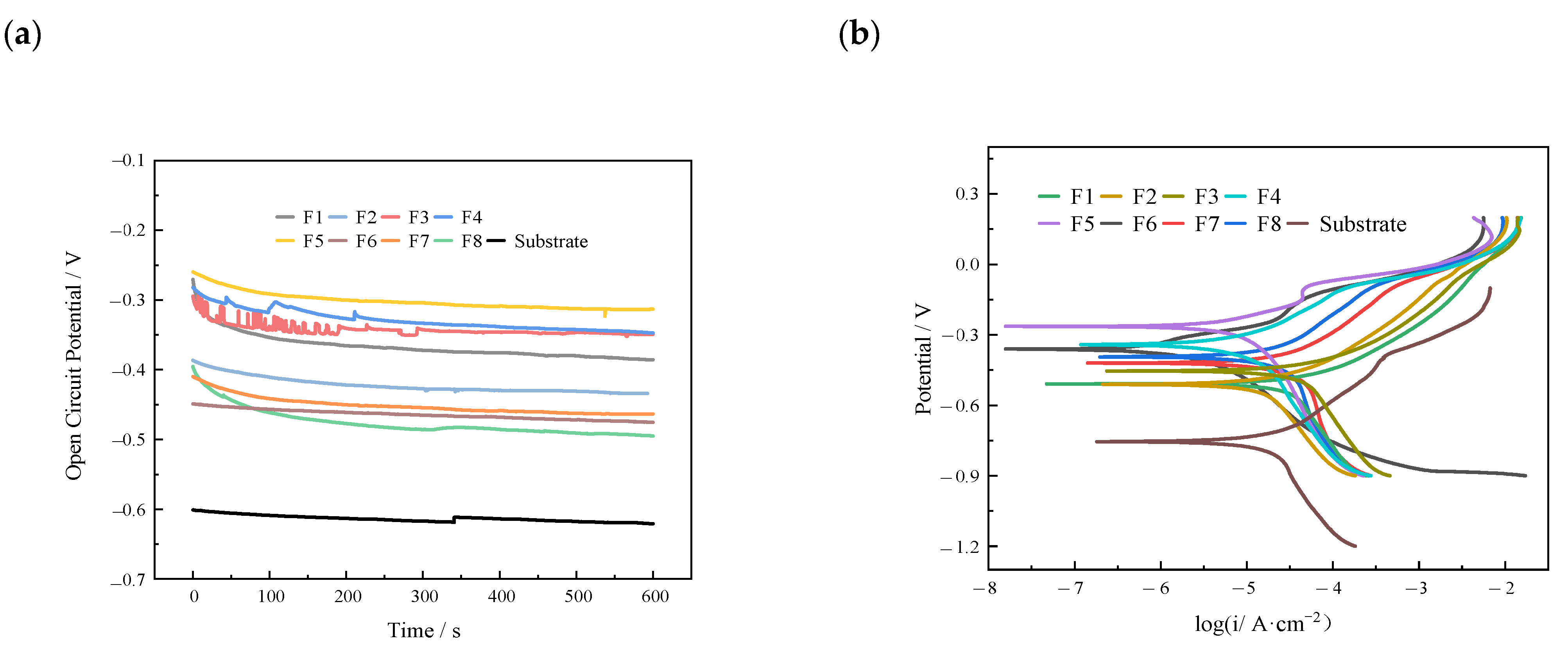
The open circuit potential (OCP) of Inconel 625 alloy was measured by applying the steady-state magnetic fields with different directions and intensities. As shown in Figure 14a, the average OCP value of the Inconel 625 cladding layer without a steady-state magnetic field was −0.475 V. When the magnetic field is added, the OCP value fluctuates greatly, and finally stabilizes between −2.5 V and −0.48 V. Compared to no steady-state magnetic field, the potential changed slightly. The higher OCP value indicated a lower corrosion tendency, and vice versa. However, there was no specific rule between the change in potential and magnetic field intensity. It is noteworthy that the OCP value of each cladding layer was higher than that of matrix HT 300 with or without a steady-state magnetic field, which can play a good cathodic protection role and show a small corrosion tendency.
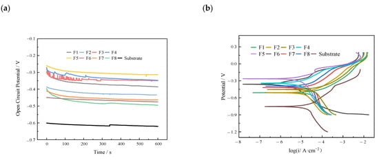
Figure 14.
(a) Cladding surface open circuit data diagram, (b) Tafel polarization curve of the cladding layer.
Figure 14b shows the Tafel test curves of the substrate and cladding layers. No obvious passivation occurred within the set VOCP ± 1 V test range. Meanwhile, the shape and position of all curves were similar and the anode rate slowed down gradually, showing a symmetric relationship independent of self-corrosion potential. As shown in Figure 14, both anode and cathode curves exhibited the characteristics of active dissolution. The shape and position of all curves were similar, and the corrosion rate slowed down as the voltage changed and gradually decreased in the anode region.
It can be seen from Table 8 that the substrate presented the smallest Ecorr, with a value of −0.76326 V, and the biggest Icorr, with a value of 0.0186231 μA/cm2, compared to the cladding layer. That is, the laser cladding layer can enhance the surface to suppress the corrosion. In addition, with the increase in the magnetic field intensity, the Ecorr increased and the Icorr decreased. For instance, the Ecorr was −0.55655 V, accompanied by the Icorr of 0.014997 μA/cm2 when the intensity was 0 mT, and the Ecorr increased to −0.30288 V, accompanied by the decreased Icorr with a value of 0.00035922 μA/cm2 when the intensity of 200 mT was used. This means that an increase in the intensity contributes to an improvement in the corrosion resistance of the cladding layers. Cr, Nb, and other elements are beneficial to increase the corrosion performance, but the precipitation of the Laves phase will injure these strengthening elements, which results in a reduction in the synthesized γ-Ni matrix phase, and thus a decrease in the overall corrosion resistance of the cladding layer. However, the increase in the magnetic field intensity increased the matrix phase content which, in turn, decreased the harmful Laves phase. Thus, an increase in the magnetic field intensity can improve the corrosion resistance of the cladding layer. Through comparing to the Ecorr and Icorr of the cladding layers created by different magnetic field directions, the cladding layer assisted by the horizontal magnetic field presented the maximum average value of Ecorr (−0.35354 V) and minimum average value of Icorr (0.00529505 μA/cm2).
Table 8.
The self-corrosion potential (Ecorr) and current density (Icorr) of the cladding layer obtained after the Tafel test.
4. Conclusions
1. A higher steady-state magnetic field intensity resulted in a slightly wider melting width of the molten pool, but reduced the melting height, depth, and dilution rate. A horizontal magnetic field flattened the molten pool more than a vertical one. Stronger magnetic fields caused the dendritic structure to change into an equiaxed crystal structure with more extensive and stronger columnar dendritic structures at the bottom of the clad layer, biased towards the magnetic field direction.
2. The magnetic field stabilized the crystal structure and refined the grain by increasing the content of the matrix phase and decreasing the content of Laves phase.
3. The cladding layer’s microhardness was higher than that of the matrix. A vertical downward steady magnetic field increased the microhardness and wear resistance. The highest hardness, lowest wear amount, and best wear performance were observed with the vertical downward magnetic field.
4. The higher the magnetic field intensity, the better the corrosion resistance of the cladding layer. The corrosion resistance is lower in the vertical direction than in the horizontal direction. Increasing the magnetic field intensity increases the matrix phase content and reduces the harmful Laves phase, leading to improved corrosion resistance of the cladding layer.
Author Contributions
Conceptualization, X.W. and J.Z.; methodology, X.W.; validation, Y.T. and J.J.; formal analysis, J.J.; investigation, Y.T.; writing—original draft preparation, X.W. and Y.T.; writing—review and editing, X.W., Y.T. and J.J.; project administration, T.G.; funding acquisition, X.W. and T.G. All authors have read and agreed to the published version of the manuscript.
Funding
This research was funded by the National Natural Science Foundation of China, grant number 52305340, the Natural Science Foundation of Liaoning Province, grant number 2020-BS-206, Liaoning Department of Education Scientific Research Foundation, grant number JDL2020022, and Scientific and technological research program of China National Railway Group Limited, grant number N2021T010.
Institutional Review Board Statement
Not applicable.
Informed Consent Statement
Not applicable.
Data Availability Statement
Data is contained within the article.
Conflicts of Interest
The authors declare no conflicts of interest.
References
- Pawlus, P.; Koszela, W.; Reizer, R. Surface Texturing of Cylinder Liners: A Review. Materials 2022, 15, 8629. [Google Scholar] [CrossRef] [PubMed]
- Li, C.; Chen, X.; Liu, H.; Dong, L.; Jian, H.; Wang, J.; Du, F. Tribological Performance and Scuffing Resistance of Cast-Iron Cylinder Liners and Al-Si Alloy Cylinder Liners. Coatings 2023, 13, 1951. [Google Scholar] [CrossRef]
- Peng, E.; Huang, S. Wear performance of cylinder liner surface texturing on cylinder liner–piston ring assembly. Proc. Inst. Mech. Eng. Part J J. Eng. Tribol. 2017, 232, 291–306. [Google Scholar] [CrossRef]
- Rahmani, R.; Rahnejat, H.; Fitzsimons, B.; Dowson, D. The effect of cylinder liner operating temperature on frictional loss and engine emissions in piston ring conjunction. Appl. Energy 2017, 191, 581. [Google Scholar] [CrossRef]
- Liu, N.; Wang, C.N.; Xia, Q.; Gao, Y.Y.; Liu, P. Simulation on the effect of cylinder liner and piston ring surface roughness on friction performance. Mech. Ind. 2022, 23, 8. [Google Scholar] [CrossRef]
- Alshwawra, A.; Pasligh, H.; Hansen, H.; Dinkelacker, F. Increasing the roundness of deformed cylinder liner in internal combustion engines by using a non-circular liner profile. Int. J. Engine Res. 2019, 22, 1214–1221. [Google Scholar] [CrossRef]
- Denkena, B.; Grove, T.; Schmidt, C. Machining of Micro Dimples for Friction Reduction in Cylinder Liners. Procedia CIRP 2018, 78, 318–322. [Google Scholar] [CrossRef]
- Alshwawra, A.; Swerih, A.A.; Sakhrieh, A.; Dinkelacker, F. Structural Performance of Additively Manufactured Cylinder Liner—A Numerical Study. Energies 2022, 15, 8926. [Google Scholar] [CrossRef]
- Haldar, B.; Saha, P. Identifying defects and problems in laser cladding and suggestions of some remedies for the same. Mater. Today Proc. 2018, 5, 13090–13101. [Google Scholar] [CrossRef]
- Kwok, C.T.; Man, H.C.; Cheng, F.T.; Lo, K.H. Developments in laser-based surface engineering processes: With particular reference to protection against cavitation erosion. Surf. Coat. Technol. 2016, 291, 189–204. [Google Scholar] [CrossRef]
- Zhang, P.; Liu, Z.; Du, J.; Su, G.; Zhang, J.; Xu, C. On machinability and surface integrity in subsequent machining of additively-manufactured thick coatings: A review. J. Manuf. Process. 2020, 53, 123–143. [Google Scholar] [CrossRef]
- Chong, Z.; Sun, Y.; Cheng, W.; Han, C.; Huang, L.; Su, C.; Jiang, L. Enhanced wear and corrosion resistances of AlCoCrFeNi high-entropy alloy coatings via high-speed laser cladding. Mater. Today Commun. 2022, 33, 104417. [Google Scholar] [CrossRef]
- Farahmand, P.; Kovacevic, R. Laser cladding assisted with an induction heater (LCAIH) of Ni–60%WC coating. J. Mater. Process. Technol. 2015, 222, 244–258. [Google Scholar] [CrossRef]
- Zhang, Z.; Zhang, Y.; Ming, W.; Zhang, Y.; Cao, C.; Zhang, G. A review on magnetic field assisted electrical discharge machining. J. Manuf. Process. 2021, 64, 694–722. [Google Scholar] [CrossRef]
- Zhu, L.; Xue, P.; Lan, Q.; Meng, G.; Ren, Y.; Yang, Z.; Xu, P.; Liu, Z. Recent research and development status of laser cladding: A review. Opt. Laser Technol. 2021, 138, 106915. [Google Scholar] [CrossRef]
- Bachmann, M.; Avilov, V.; Gumenyuk, A.; Rethmeier, M. Numerical assessment and experimental verification of the influence of the Hartmann effect in laser beam welding processes by steady magnetic fields. Int. J. Therm. Sci. 2016, 101, 24–34. [Google Scholar] [CrossRef]
- Bachmann, M.; Avilov, V.; Gumenyuk, A.; Rethmeier, M. About the influence of a steady magnetic field on weld pool dynamics in partial penetration high power laser beam welding of thick aluminium parts. Int. J. Heat Mass Transf. 2013, 60, 309–321. [Google Scholar] [CrossRef]
- Velde, O.; Gritzki, R.; Grundmann, R. Numerical investigations of Lorentz force influenced Marangoni convection relevant to aluminum surface alloying. Int. J. Heat Mass Transf. 2001, 44, 2751–2762. [Google Scholar] [CrossRef]
- Lee, C.-K.; Lee, W. The effect of magnetic fields for laser welding process using carbon steel. Int. J. Precis. Eng. Manuf. 2013, 14, 1915–1923. [Google Scholar] [CrossRef]
- Qi, K.; Yang, Y.; Sun, R.; Hu, G.; Lu, X.; Li, J.; Liang, W.; Jin, K.; Xiong, L. Effect of magnetic field on crack control of Co-based alloy laser cladding. Opt. Laser Technol. 2021, 141, 107129. [Google Scholar] [CrossRef]
- Qi, K.; Yang, Y.; Liang, W.; Jin, K.; Xiong, L. Influence of the anomalous elastic modulus on the crack sensitivity and wear properties of laser cladding under the effects of a magnetic field and Cr addition. Surf. Coat. Technol. 2021, 423, 127575. [Google Scholar] [CrossRef]
- Wang, L.; Yao, P.H.; Hu, Y.; Song, S.Y. Suppression effect of a steady magnetic field on molten pool during laser remelting. Appl. Surf. Sci. 2015, 351, 794–802. [Google Scholar] [CrossRef]
- Hu, Y.; Wang, L.; Yao, J.; Xia, H.; Li, J.; Liu, R. Effects of electromagnetic compound field on the escape behavior of pores in molten pool during laser cladding. Surf. Coat. Technol. 2020, 383, 125198. [Google Scholar] [CrossRef]
- Wang, L.; Yao, J.; Hu, Y.; Zhang, Q.; Sun, Z.; Liu, R. Influence of electric-magnetic compound field on the WC particles distribution in laser melt injection. Surf. Coat. Technol. 2017, 315, 32–43. [Google Scholar] [CrossRef]
- Carroll, R.I.; Beynon, J.H. Rolling contact fatigue of white etching layer, Part 1: Crack morphology. Wear 2007, 262, 1253–1266. [Google Scholar] [CrossRef]
- Fujimoto, K.; Yoshikawa, Y.; Shioya, T. Opening Behaviour Of Surface Crack in ElasticHalf-plane Under Hertzian Contact Loading. In WIT Transactions on Engineering Sciences; WIT Press: Southampton, UK, 1997; Volume 14. [Google Scholar]
- Jia, G.W.; Hua, L.; Mao, H.J. The influence of surface layer microstructure evolution of M2 steel cold-ring rolling mandrel roller on fatigue crack initiation. J. Mater. Process. Technol. 2007, 187, 562–565. [Google Scholar] [CrossRef]
- Mercado-Solis, R.D.; Talamantes-Silva, J.; Beynon, J.H.; Hernandez-Rodriguez, M.A.L. Modelling surface thermal damage to hot mill rolls. Wear 2007, 263, 1560–1567. [Google Scholar] [CrossRef]
- Cerullo, M. Sub-surface Fatigue Crack Growth at Alumina Inclusions in AISI 52100 Roller Bearings. Procedia Eng. 2014, 74, 333–338. [Google Scholar] [CrossRef]
- Ohtsuka, H. Structural control of Fe-based alloys through diffusional solid/solid phase transformations in a high magnetic field. Sci. Technol. Adv. Mater. 2008, 9, 13004. [Google Scholar] [CrossRef]
- Li, X.; Fautrelle, Y.; Zaidat, K.; Gagnoud, A.; Ren, Z.; Moreau, R.; Zhang, Y.; Esling, C. Columnar-to-equiaxed transitions in al-based alloys during directional solidification under a high magnetic field. J. Cryst. Growth 2010, 312, 267–272. [Google Scholar] [CrossRef]
- Shuai, S.S.; Lin, X.; Xiao, W.Q.; Yu, J.B.; Wang, J.; Ren, Z.M. Effect of Transverse Static Magnetic Field on Microstructure of Al-12% Si Alloys Fabricated by Powder-Blow Additive Manufacturing. Acta Met. Sin. 2018, 54, 926. [Google Scholar]
- Li, X.; Gagnoud, A.; Ren, Z.; Fautrelle, Y.; Moreau, R. Investigation of thermoelectric magnetic convection and its effect on solidification structure during directional solidification under a low axial magnetic field. Acta Mater. 2009, 57, 2180–2197. [Google Scholar] [CrossRef]
- Wang, Q.; Zhai, L.L.; Zhang, L.; Zhang, J.W.; Ban, C.Y. Effect of steady magnetic field on microstructure and properties of laser cladding Ni-based alloy coating. J. Mater. Res. Technol. 2022, 17, 2145–2157. [Google Scholar] [CrossRef]


Disclaimer/Publisher’s Note: The statements, opinions and data contained in all publications are solely those of the individual author(s) and contributor(s) and not of MDPI and/or the editor(s). MDPI and/or the editor(s) disclaim responsibility for any injury to people or property resulting from any ideas, methods, instructions or products referred to in the content. |
© 2024 by the authors. Licensee MDPI, Basel, Switzerland. This article is an open access article distributed under the terms and conditions of the Creative Commons Attribution (CC BY) license (https://creativecommons.org/licenses/by/4.0/).