Review

A Review of Corrosion-Resistant PEO Coating on Mg Alloy

1
National Engineering Research Center of Light Alloy Net Forming, School of Materials Science and Engineering, Shanghai Jiao Tong University, Shanghai 200240, China
2
Key Laboratory of Hunan Province of Equipment Safety Service Technology under Extreme Environment, College of Mechanical Engineering, University of South China, Hengyang 421001, China
3
Shenzhen Institute, Peking University, Shenzhen 518057, China
4
Department of Physics, City University of Hong Kong, Tat Chee Avenue, Kowloon, Hong Kong 999077, China
5
Department of Materials Science & Engineering, City University of Hong Kong, Tat Chee Avenue, Kowloon, Hong Kong 999077, China
6
Department of Biomedical Engineering, City University of Hong Kong, Tat Chee Avenue, Kowloon, Hong Kong 999077, China
*
Author to whom correspondence should be addressed.
Coatings 2024, 14(4), 451; https://doi.org/10.3390/coatings14040451
Submission received: 22 March 2024 / Revised: 5 April 2024 / Accepted: 6 April 2024 / Published: 9 April 2024
(This article belongs to the Special Issue Investigation on Corrosion Behaviour of Metallic Materials)

Abstract

:
The corrosion problem of Mg alloy limits its application in many engineering fields. Plasma electrolytic oxidation (PEO) is an economical and eco-friendly technology that can create a dense oxide layer on Mg alloy, offering a solution to the corrosion issue. This research summarizes the use of PEO technology in developing corrosion-resistant coatings for Mg alloys and examines the growth mode and corrosion process of PEO coatings. It is concluded that current efforts to enhance the corrosion resistance of PEO coatings on Mg alloys can be categorized into two approaches: improving the internal structure of the coating and enhancing the phase composition. This includes optimizing coating thickness, roughness, and density; repairing micropores and cracks; and introducing corrosion-resistant compounds by doping. Micropores and cracks are identified as vulnerable points for corrosion, and sealing is an effective strategy to address this. By modifying the phase composition of the coating, corrosion occurrence can be minimized, significantly boosting the corrosion resistance of Mg alloys. Finally, future challenges and potential advancements in corrosion-resistant PEO coatings for Mg alloys are discussed.

1. Introduction

Mg alloy is the lightest metal material in engineering applications, with a density of only 2/3 that of Al and 1/4 that of Fe. It possesses excellent properties such as low density, high strength, good processability, and recyclability, resulting in minimal environmental pollution [1,2,3]. The use of Mg alloy has significantly reduced the weight of vehicles, enhanced the aerodynamic performance of transportation vehicles, and contributed to energy conservation, emission reduction, impact resistance, and shock absorption. As a result, it is extensively utilized in the aerospace and transportation manufacturing industries. However, due to the high chemical activity of the Mg alloy, it exhibits poor corrosion resistance, particularly in marine environments. Surface treatment technology serves as an effective and common method to enhance the corrosion resistance of Mg alloys. Common techniques for corrosion protection include chemical electrodeposition, electroplating, anodizing, vapor deposition, and organic coating [4,5,6,7,8]. In recent years, plasma electrolytic oxidation technology (PEO), based on anodizing, has gained recognition and popularity among scholars [9,10]. This technology, also known as micro-arc oxidation or anodic spark deposition technology, offers advantages such as a simple process, ease of operation, and no limitation by the shape of the workpiece. It has been extensively studied and applied to enhance the surface hardness and corrosion resistance of materials. This study presents a summary of recent research on corrosion-resistant PEO coatings of Mg alloy, starting with the generation process and corrosion process of PEO coatings on Mg alloy. It further elaborates on the primary strategies to enhance corrosion resistance, which include improving the internal structure of coatings and regulating the phase composition of coatings. Lastly, the challenges of PEO technology on Mg alloy are discussed, and the design of corrosion-resistant PEO coatings on Mg alloy is projected for the future.

2. Growth and Corrosion Process of PEO Coating on Mg Alloy

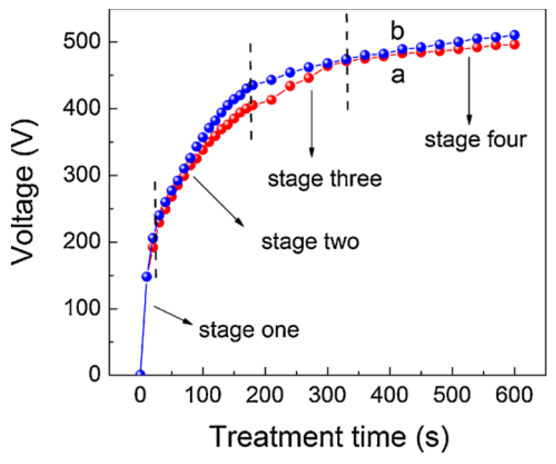
2.1. Growth of PEO Coating

The growth process of PEO coatings on the Mg alloy is influenced by the type of electrolyte and the electrical parameters. Based on the plasma discharge behavior of the coating, its growth process can be divided into four stages (Figure 1) [11]. Initially, a rapid formation of an oxide film of about 1 μm occurs on the surface without any arc light generation. As the voltage increases, the dissolution rate of the oxide film increases, leading to the first stage—the traditional anodizing stage. When the actual voltage reaches the oxide breakdown voltage, the oxide film formed by anodizing is punctured, and bright low-density arcs appear on the surface of the Mg alloy, marking the beginning of the second stage—the spark discharge stage (as shown in Figure 2). As the voltage continues to rise, the arcs gradually grow larger and brighter, causing the surface temperature of the Mg alloy to sharply rise. This leads to rapid melting and cooling of the oxide, forming a dense PEO coating, and transitioning the reaction into the third stage—the micro-arc oxidation stage, which is the primary stage for ceramic film formation. With a prolonged reaction time, the process enters the fourth stage. With an increase in coating thickness, breakdown discharge requires more energy, resulting in two trends in discharge: either the arc light disappears due to insufficient energy density on the sample surface or intense arc discharge occurs in several regions, causing intense and prolonged arc light that results in coating burn damage [12].
The composition of the coatings prepared from different electrolytes varies, with the most common systems being silicate and phosphate electrolytes. The following reactions take place on the Mg alloy during the PEO process:
Mg → Mg2+ + 2e.
As the reaction progresses, a large amount of MgO is generated in the coating. The reaction is as follows:
Mg2+ + OH → Mg(OH)2,
Mg(OH)2 → MgO + H2O.
In the silicate electrolyte system, the phase composition of its PEO coating is depicted in Figure 3. The electrolyte is typically alkaline, and as it diffuses into the coating, the following reactions take place:
2Mg2+ + SiO32− + 2OH → Mg2SiO4 + 2H2O,
Mg2+ + SiO32− → MgSiO3.
Mg2+ ions from the matrix reach the interface of the coating/electrolyte and react with the silicates in the solution. Meanwhile, the MgO and Mg2SiO4 in the coating undergo a transformation into the stable MgSiO3 [13]. For the phosphate electrolyte, the composition of its PEO coating is depicted in Figure 4. The reaction is as follows:
Mg2+ + PO43− → Mg3(PO4)2,
Mg2+ ions from the matrix reach the interface of the coating/electrolyte and react with PO43− to form Mg3(PO4)2. Magnesium phosphate itself is a sparingly soluble stable phase, making it difficult to further react with MgO. In this process, Mg3(PO4)2 mainly exists in an amorphous phase [13].

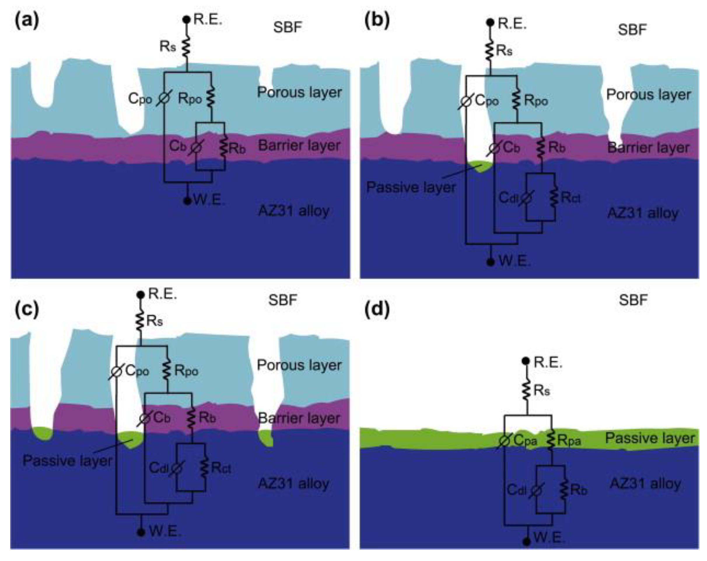
2.2. Corrosion of PEO Coating

Although the chemical composition of coatings prepared with different electrolytes varies, the overall structure of PEO coatings remains essentially the same, consisting of an internal dense layer and an external porous layer (Figure 5). Due to differences in reaction stages and electrolyte characteristics, there are often significant variations in the distribution and structure of elements within the inner and outer layers [14]. The outer layer typically contains micropores and cracks, with a distinct boundary separating it from the inner layer, serving as an initial barrier against corrosion media. The inner layer, on the other hand, is characterized by higher density and resistance levels approximately 8–10 times greater than those of the outer layer, effectively slowing down the rate of corrosion electrochemical reactions [15]. Ultimately, the inner layer structure acts as the primary barrier for corrosion protection in PEO coatings.
However, as the contact time with the corrosive medium is prolonged, the coating will eventually be destroyed by SBF [16]. Taking the typical NaCl solution as an example, the corrosion process is divided into two stages. Before corrosion occurs, the outer layer resistance Rpo obtained by EIS fitting is about 1000–2000 Ω, while the inner layer resistance Rb represents about 7000–10,000 Ω [15]. In the first stage, when the corrosive liquid NaCl solution contacts the outer surface, it preferentially enters holes and cracks, causing MgO to begin to dissolve, reacting to generate Mg(OH)2 attached to the surface. Additionally, due to the influence of alloy elements, the second phase, and β-Mg of the Mg alloy, the coating has structural defects such as the AlMn phase, causing localized stress during the coating growth process, making the coating more susceptible to corrosion [17]. The generation of corrosion products, to some extent, blocks the entry of the NaCl solution, slowing down the ion exchange process. As Cl gradually replaces O, forming MgCl2, the corrosion enters the second stage. In this stage, the dissolution rate of the coating accelerates and is greater than the rate of Mg(OH)2 generation, causing the corrosion products to gradually dissolve in the NaCl solution, forming pit corrosion, eventually penetrating through the entire coating [18]. At the same time, the directional corrosion at the surface defects connects to other pits, allowing more NaCl solution to enter and react with the Mg matrix, increasing the amount of corrosion products and gas [10], increasing stress, and ultimately leading to the failure and detachment of the entire coating [9], as shown in Figure 6. For coatings prepared with silicate and phosphate, there are some differences in the corrosion process. In the early stage of the phosphate film formation, the passivation film generated is more stable, making it easier for corrosion products to accumulate on the surface once corroded to the base, while the silicate overall coating is more uniform, allowing corrosion products to directly overflow along the holes, resulting in a greater surface difference after corrosion between the two, as shown in Figure 7 [19]. At this point, the outer layer resistance Rpo obtained by EIS fitting decreases to 400 Ω, while the inner layer resistance Rb can still remain far higher than that of the outer layer, maintained at 3000 Ω.

3. Improvement of the Coating Structure

In the preparation process, structural defects in PEO coatings are unavoidable, which limits their corrosion resistance improvement. The formation of PEO coatings involves various disciplines, such as chemistry, electrochemistry, thermodynamics, and plasma chemistry. However, the growth of coatings is primarily controlled by reaction energy. The energy of the coating is reflected on a macroscopic level in the arc discharge behavior, which, in turn, affects the internal structure of the coating. The micro-pores and cracks that form during coating growth are susceptible to corrosion liquid infiltration, which is essential for the coating’s corrosion resistance. Additionally, the roughness, uniformity, and density of the coating all impact the infiltration of corrosion liquid and the occurrence of corrosion reactions.

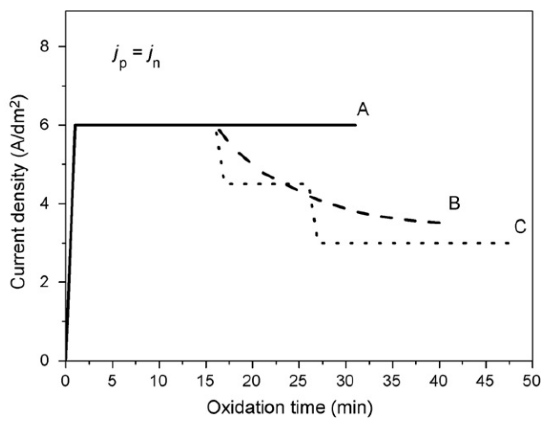
3.1. The Influence of Discharge Behavior on the Coating Structure

The growth of the coating is determined by the reaction energy, which is mainly reflected in the discharge behavior. Increasing the energy of PEO coatings can be most directly achieved by changing the electrical parameters. This involves increasing the input energy to the coating, but simply increasing the input energy is often unsatisfactory because the PEO process is complex and energy control does not follow Faraday’s law for discharge. Discharge is generally divided into solid breakdown and gas breakdown, with each method resulting in different types of discharge [11].
Currently, there are three different discharge modes on the PEO coating, and the discharge behavior is closely related to the coating structure [20]. As shown in Figure 8, the discharge modes can be distinguished by the different element contents near the micro-holes. The first type (type A) is the breakdown of the oxide film in a strong electric field, which often occurs in small holes on the surface at the interface between the electrolyte and the coating, with more electrolyte solution elements. The corresponding fine hole on the surface corresponds to a discharge with fewer defects due to the weak discharge intensity. The second type (type B) is gas discharge through initial dielectric breakdown in micro-holes, occurring on the surface of the metal-oxide film. The surface morphology formed is crater-like, also known as a “thin pancake”, inevitably carrying molten material ejected from the discharge channel during surface contact with the electrolyte. The high content of matrix elements near the micro-holes, originating from the matrix, leads to a higher temperature, and excess energy enhances the transformation from the amorphous phase to the crystalline phase. However, as the central hole penetrates deep into the coating, the corrosion resistance of the coating will decrease. The third type (type C) is arc discharge between free electrons in the gas medium on the coating surface and the electrolyte, occurring in deeper surface apertures with higher matrix elements compared to the first type of discharge behavior. It occurs at high discharge intensity and causes coating damage, overflowing with a large amount of molten material, forming a spherical surface. Dehnavi et al. [21] mainly used 20 g/L NaOH, 80 g/L Na2SiO3·5H2O, and 80 g/L Na2B4O7·10H2O solutions to prepare coatings with type A and type C discharges as the main types, significantly improving the resistance value of the coatings and enhancing their corrosion resistance (Figure 9).

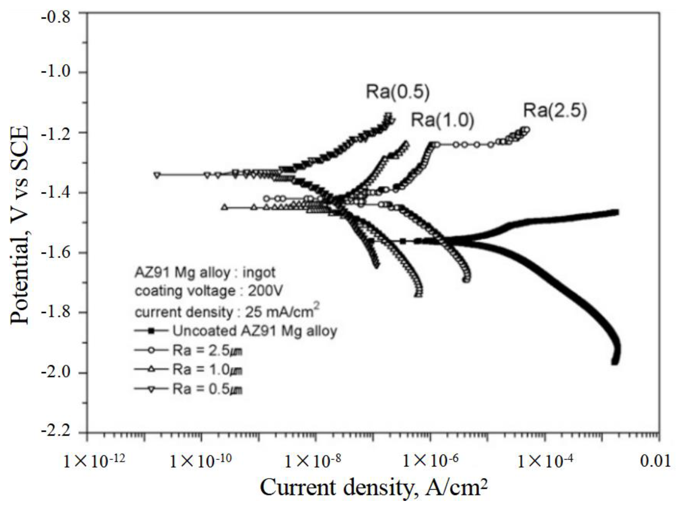
3.2. The Influence of Coating Roughness on the Corrosion

The roughness of the coating refers to the size of the spacing between two peaks or valleys, and splashing molten oxides generated during the coating growth process will result in a rough surface with certain geometric errors. Reducing the relative surface roughness can improve the contact area between the coating surface and the corrosive liquid, thus reducing the probability of corrosion [22]. The rough surface of the coating easily allows gas or liquid to penetrate into the inner layer through the valleys on the surface, thereby affecting the corrosion resistance of the coating. Furthermore, high roughness will reduce the wear resistance and fatigue strength of the coating, limiting its comprehensive application [23]. Generally, the current density has a significant impact on the roughness of the coating, as a high current density leads to a high gas evolution rate and gas resistance, causing an increase in coating roughness. Rapheal et al. conducted experiments using current densities of 30, 60, and 120 mA/cm2, and the results showed a significant increase in coating roughness, while the corrosion resistance decreased due to the increased roughness [24]. Therefore, researchers often add different particles or organic substances to the electrolyte solution to reduce the gas evolution of the coating. Wu et al. [25] added glycerol as an additive to the electrolyte solution, reducing the mean square roughness of the coating from 424 nm to 174 nm. The corrosion current density of the coating decreased by two orders of magnitude to 10−7 J/(A·cm2).

3.3. The Influence of Coating Thickness on Corrosion

Thicker coatings typically have higher corrosion resistance [26]. By extending the reaction time, it is possible to achieve a higher coating thickness. Liu et al. [27] were able to increase the coating thickness even further by using sodium citrate as an electrolyte, resulting in a tenfold decrease in corrosion current density. Generally, the outer layer of the coating contains more defects and holes, so the delay in corrosion is more dependent on the thickness of the outer layer than the inner layer. The thickness of the coating growth depends on various factors, such as the substrate, electrical parameters, and electrolyte solution used. The presence of different alloying elements in the substrate results in variations in the growth rate and uniformity of the coating during the filming process [14]. For example, the presence of the AlMn phase and β-Mg can impact the coating growth [17]. Additionally, the roughness of the substrate also plays a significant role in the thickness of the coating. As shown in Figure 10, Yoo et al. [28] demonstrated that a substrate with a roughness of 0.5 μm had a considerable improvement in thickness compared to a substrate with a roughness of 2.5 μm. This not only reduced the residual stress within the coating but also decreased the corrosion current density from 10−7 J/(A·cm2) to 10−9 J/(A·cm2). A lower substrate roughness leads to more uniform surface discharge, thereby increasing the coating growth rate and enhancing the mechanical properties of the coating.
The improvement in coating thickness in the PEO reaction process is more noticeable with changes in electrical parameters and electrolyte solution. Changes in electrical parameters will affect the rate of gas generation and particle movement during the coating growth process. The longer the reaction time, the thicker the coating becomes, and the corrosion resistance of the coating shows a trend of initial improvement followed by a decline with increasing coating thickness. Generally, the thickness of PEO coatings ranges between 20 and 55 μm. When the reaction time exceeds 60 min, the coating thickness increases significantly, but excessively long reaction times can cause coating ablation [29]. As illustrated in Figure 11, Chen et al. [30] conducted tests on the electrochemical properties of coatings at different times and discovered that with an extension of reaction time, the electrical resistance of the coating decreased due to the increase in coating defects. Moreover, the increase in coating thickness, to some extent, obstructed the entry of corrosion solution. Adding other electrolytes to enhance the average film-forming rate can effectively increase the thickness. For instance, adding sodium citrate to improve the conductivity of the solution can enhance the adhesion of the inner coating, thus facilitating more electrolytes to react with overflowed Mg2+ and increasing the thickness of the coating [27].

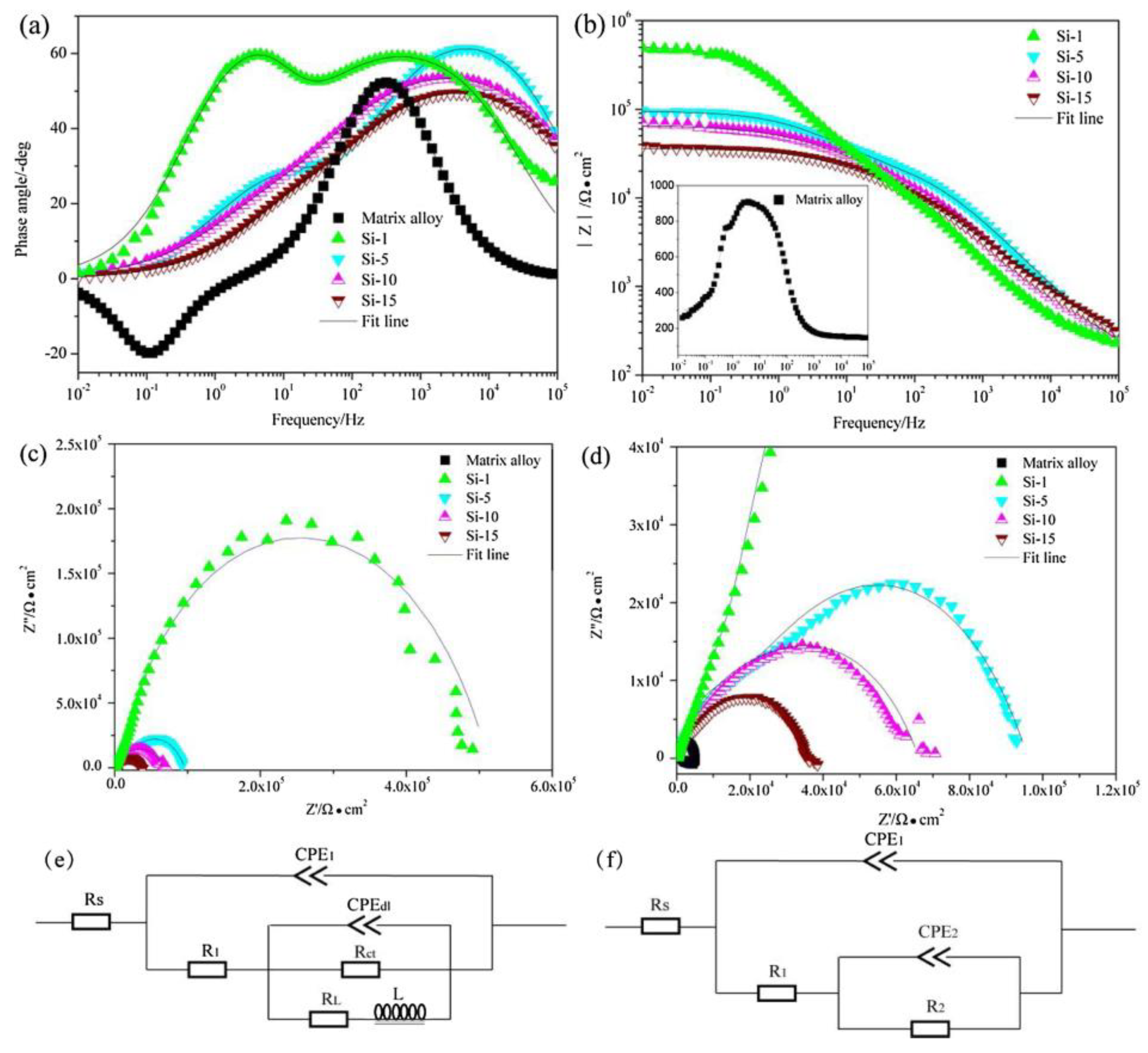
3.4. The Influence of Coating Density on Corrosion

High-density coatings can increase the difficulty for corrosive liquids to reach the inner layer, which is usually reflected in the resistance value of the coating per unit thickness. The resistance value of the coating is divided into an inner layer resistance value and an outer layer resistance value (Figure 5). Better density makes the outer layer resistance value increase by 1–2 orders of magnitude. This improvement has a significant impact on the corrosion resistance time in a 3.5% NaCl solution [16]. The inner layer structure of the coating with a resistance value higher than 8–10 times that of the outer layer is crucial. Due to the challenges of increasing the thickness of the inner layer, reducing defects in the inner layer is essential. Exterior defects are generally not connected to the inner layer, but the presence of electrolytes can lead to defects in the passive film generated in the initial reaction stages or due to excessive reaction time, causing partial dissolution of the passive film and a decrease in the resistance value of the inner layer. This, in turn, can lead to defects connecting the inner and outer layers, resulting in a decrease in the coating’s corrosion resistance [31]. Gaps in the substrate structure may lead to incomplete formation of the passive film due to electrolytes and arc discharges. Han et al. [32] suggest that incomplete film formation can cause exterior defects to extend to the inner layer, decreasing the inner layer resistance value by one order of magnitude. Zhao et al. [33] found that adding substances like graphite oxide can create additional thin layers between the inner and outer layers, isolating the inner layer from the outer layer. The high surface area, strong van der Waals forces, and pi-pi stacking properties of this thin layer can reduce the corrosion current density to the level of 10−9 orders of magnitude. Additionally, Tran et al. [34] indicated that increasing current density or frequency can affect the flow of ions in a single-arc discharge reaction. Changes in frequency can lead to overflowing of Mg2+ ions and alterations in the return flow of anions, impacting the movement of molten material on the surface and affecting the coating’s density. Dong et al. [35] developed a high-frequency discharge PEO technology that significantly shortened the single discharge time by increasing the number of power supply pulses. This technology can increase the discharge frequency of the coating, reduce the risk of breakdown, greatly enhance the coating’s density, and significantly improve corrosion resistance (Figure 12).

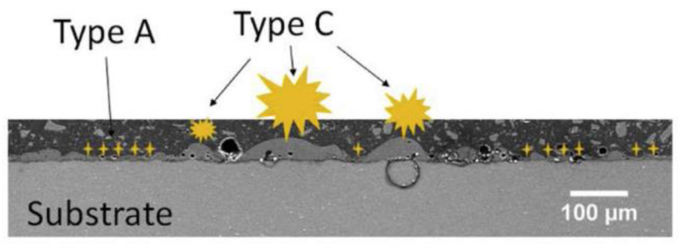
3.5. The Influence of Coating Micropores and Defects on Corrosion

During the PEO reaction process, splashing of molten oxides is unavoidable, resulting in the formation of micro-pores on the PEO coatings. These pores accelerate the infiltration of corrosive liquids, triggering corrosion reactions that ultimately lead to the breakdown of the coating. Porosity and pore size are typically used to describe the micro-pores of the coating. As the current density increases or the reaction time lengthens, the resistance of the coating also increases. This results in a longer duration of high-density arc glow, causing the pore size and number to increase. However, as the thickness of the coating increases, current density decreases, leading to a decrease in arc glow. This transition from granular to blocky surface molten material results in larger pore sizes that no longer increase in size and gradually decrease in number. This reduces the entry of corrosive liquids and improves the corrosion resistance of the coating. It is important to note that higher current density can also lead to coating defects, which can in turn reduce the corrosion resistance of the coating. Chen et al. [36] have shown that high current density can result in outward growth of the coating at a much faster rate than inward growth. This leads to deeper pore sizes and more corrosion sites, ultimately reducing the corrosion resistance of the coating.
The pore ratio often changes due to variations in sparks. The increase in thickness in the later stage of the reaction results in larger individual sparks and a decrease in the number of sparks, causing the overall porosity of the coating to initially increase and then decrease, with a porosity rate between 0.2% and 10%. In addition to conventional methods for controlling the corrosion medium channel, sealing methods are becoming more popular. Common sealing methods are primarily divided into three types. The simplest approach is a two-step method to seal the pores, relying on different reactions in different electrolyte solutions to create a sealing effect by generating substances of varying sizes. For example, Dou et al. [37] first used a silicate solution to react for 300 s, followed by immersion in a phosphate solution to achieve sealing (Figure 13). This resulted in a decrease in corrosion current density from 10−6 J/(A·cm2) to 10−8 J/(A·cm2). The two-step method not only seals the underlying coating but also prevents film formation due to electrical conductivity. By utilizing different solidification times of the reaction products, substances with faster solidification times accumulate near or within the pores, effectively blocking them to achieve a sealing effect. Materials such as zirconium oxide [38] and zinc oxide [32] can be used for this purpose (Figure 14). As the reaction progresses, the leached Mg2+ reacts with the electrolyte solution, depositing into the interior, while high-melting-point substances from the surface reaction solidify into block-shaped solids or sol-gel particles, combining with a high porosity rate to effectively seal the pores [39].
The second method involves using different current modes to achieve the same effect as the current output mode (Figure 15) [40,41]. A high current density increases coating porosity significantly. By gradually reducing the current density, the surface arc weakens while the overall voltage remains stable. The molten material shifts from block to granule, and the low energy lowers the temperature of the generated substances, creating an effect similar to differences in melting points and achieving pore sealing. It is important to note that using a stepwise reduction in current or gradually decreasing pressure may not consistently alter the size of the arc, resulting in less noticeable effects. The third method involves a composite sealing approach. Despite the sealing methods mentioned above, PEO coatings may still have micropores and cracks that require additional sealing. Through composite sealing technology, PEO coatings can undergo secondary treatment, significantly enhancing corrosion resistance. Techniques such as electrophoresis, chemical immersion, and gel can be employed for sealing the coating, enabling it to withstand neutral salt spray tests for over 1000 h [42]. Additionally, the composite method can improve other properties, like wear resistance and impact resistance. However, this method is complex and costly, with limitations in its applicability.
The generation of cracks is mainly due to the discharge holes formed by spark discharge passing through stress accumulation, the rapid cooling and solidification of molten material producing residual stress, and the release of residual stress generated by adjacent spark reactions. Snnivasan et al. [43] indicated that stress corrosion cracks make coatings more susceptible to exposure to corrosive liquids, thereby accelerating the corrosion process. Furthermore, there are ways such as uneven element distribution leading to large differences in the rate of molten material deposition and the generation of cracks. Adding appropriate phosphates to silicate solutions can effectively improve the corresponding conditions, increase the compactness of coatings, reduce arc size, and thereby reduce cracks. Luo et al. [44] showed that adding 5 g/L of sodium hexametaphosphate to PEO electrolytes can reduce the corrosion current density of the coating to 108 J/(A·cm2). However, excessive phosphate can also affect the coating generation rate, leading to increased sparks and an increase in the corrosion current density to 106 J/(A·cm2). In addition, using ultrasound can improve the concentration of sparks on the coating, effectively increasing the reaction area, dispersing the molten material more evenly, reducing stress generation, and making the reaction more uniform, thereby reducing coating stress and decreasing the corrosion current density [45]. An et al. [46] used EDTA-2Na as an additive, as its hydrophilic groups (-COOH and -NH2) preferentially react with Mg2+, reducing the solid–liquid interface tension, uniformly adsorbing anions, and decreasing spark intensity with subsequent breakdown discharge, ultimately reducing cracks and decreasing the corrosion current density to 106 J/(A·cm2). Similarly, organic compounds such as glycerol have the same effect on improving cracks [25].

4. Improvement of the Coating Phase Composition

The structure of the coating primarily serves to restrain and slow down the immersion of corrosion solution and the spread of corrosion, while also reducing the stress that remains during the preparation process of the PEO coating. The main cause of corrosion is the dissolution of the coating and the damage inflicted by corrosion products on the coating. The phase composition and unique structure that form within the coating are crucial in inhibiting the dissolution and corrosion reactions of the coating. Transition metal compounds are commonly utilized in the electrolyte, relying on arc discharge to deposit insoluble substances onto the coating in order to alter the phase composition of the surface layer and inhibit corrosion. Simultaneously, transition metals create composite coatings on PEO ceramic films through processes of reaction, fusion, and solidification.

4.1. The Influence of PEO Electrolyte on Corrosion

Silicates are often utilized in conjunction with fluorides or hydroxides for the creation of coatings, typically containing hard-to-melt glassy materials like MgSiO3 and Mg2SiO3. These materials, which are insoluble in water, act as the primary passivators during the initial stages of film development. Boosting the amount of sodium silicate can effectively lower the arc initiation voltage, thereby decreasing the initial oxidation time. On the other hand, prolonging the PEO reaction time enhances the formation of MgSiO3. The dominant phase in the coating is MgO, and elevating the silicate content in the electrolyte can raise the percentage of MgSiO3 in the coating. This results in a salt spray corrosion time of up to 250 h [47]. Nevertheless, due to the rapid rate of silicate film formation, the resulting coating tends to have poor density, often showing Mg-Al phases and α-Mg in surface analysis (in the matrix or electrolyte containing Al).
When preparing a phosphate coating, the arc voltage is higher, and the reaction time in the first stage is longer. Phosphate salts, such as sodium phosphate, can effectively promote the generation of electric sparks [44], but the growth rate of the coating is lower [29]. The sparks are usually finer than those formed during silicate film formation. The addition of Al elements can typically increase the growth rate of the coating. Coatings prepared with phosphate rely on the lower solubility product constant of magnesium phosphate to improve the corrosion resistance of the coating. Typically, Ca, Zn, and other elements are added to form compounds with even lower solubility product constants [48], while also reducing the surface MgO content to ultimately achieve corrosion resistance. Phosphates are often added as additives to silicate electrolyte solutions to improve the density of the coating. Phosphates easily enter the coating interior through the discharge channel, resulting in a more uniform distribution of elements in the coating (Figure 16) [11]. The discharge in the coating becomes more intense, promoting the conversion of magnesium oxide to magnesium silicate. Phosphates and other ions in the solution form compounds, ultimately reducing the MgO/Mg2SiO3 ratio in the coating and improving its corrosion resistance.

4.2. The Influence of Added Compounds on Corrosion

In recent years, by adding compounds to the coating, such as powders and particles, or forming corresponding composite coatings through the process of melting and solidification after reaction, the coating has been conducive to hindering the substitution of Cl for O in MgO during the corrosion process, thereby improving the corrosion resistance of the coating [17]. Currently, silicate electrolyte solutions are mostly used, and the reaction produces a glass-like solid phase, which enhances the toughness of the coating, reduces cracks and internal stresses, and facilitates the particles to melt into the coating [20]. For example, adding zinc sulfate to the electrolyte can form [Zn(OH)4]2− on the coating, increasing the anodic resistance and making it more difficult for the coating to breakdown. The larger reaction energy promotes the transformation of [Zn(OH)4]2− on the coating into ZnO and reacts with the overflowed Mg2+ from the substrate to form the Mg-O-Zn structure [49]. Li et al. [50] found that Zr4+ ions have the same effect. Tu et al. [51] found that W forms a bright material band at the bottom of the coating, depositing WxOy oxide with the inner layer, and the addition of W results in a greater spark density on the surface, forming an insulating Mg-O-Al layer. Among many methods for preparing composite PEO coatings, the most direct way is to add particles or powder substances, so that they directly form alloy compounds with molten magnesium oxide during the reaction process, thereby improving the corrosion resistance of the coating. For example, by adding micrometer-sized sodium silicate particles, the particles form silicon dioxide in the discharge process, entering the PEO coating along with the cracks and accumulating in the corresponding positions, although it may sacrifice the uniformity of the coating to some extent [52]. The smaller the powder or particles, the more evenly distributed they are in the coating. Studies have shown that the ability of particles to enter the coating is related to the electric field force and the size of the pores, with larger pore sizes in the coating allowing for easier entry of particles, while the electric field force affects the solidification of molten substances and ion backflow, thereby affecting the entry and adsorption capacity of particles [33]. Yang et al. [53] doped high-content ZnO nanoparticles in the PEO coating of the AZ31B Mg alloy and found that the particles can plug the surface pores while ZnO is uniformly distributed in nano-crystalline form through re-melting behavior in the interior of the coating, resulting in a significant improvement in the corrosion resistance of the coating and increasing the neutral salt spray life to 2000 h (Figure 17).

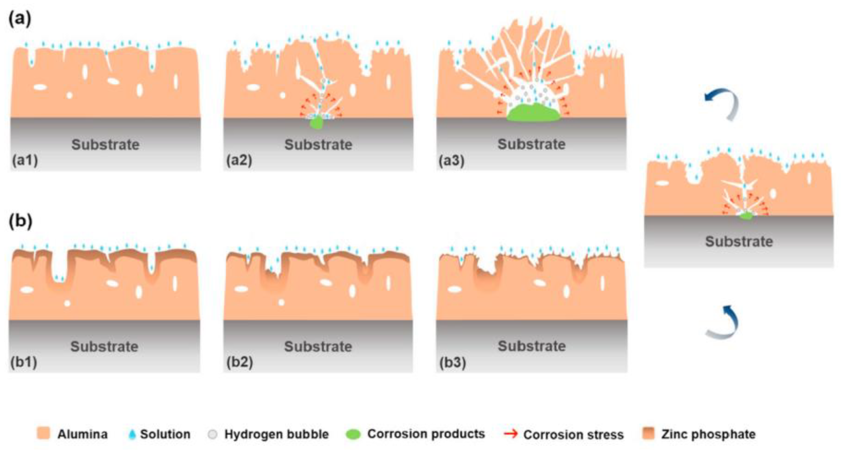
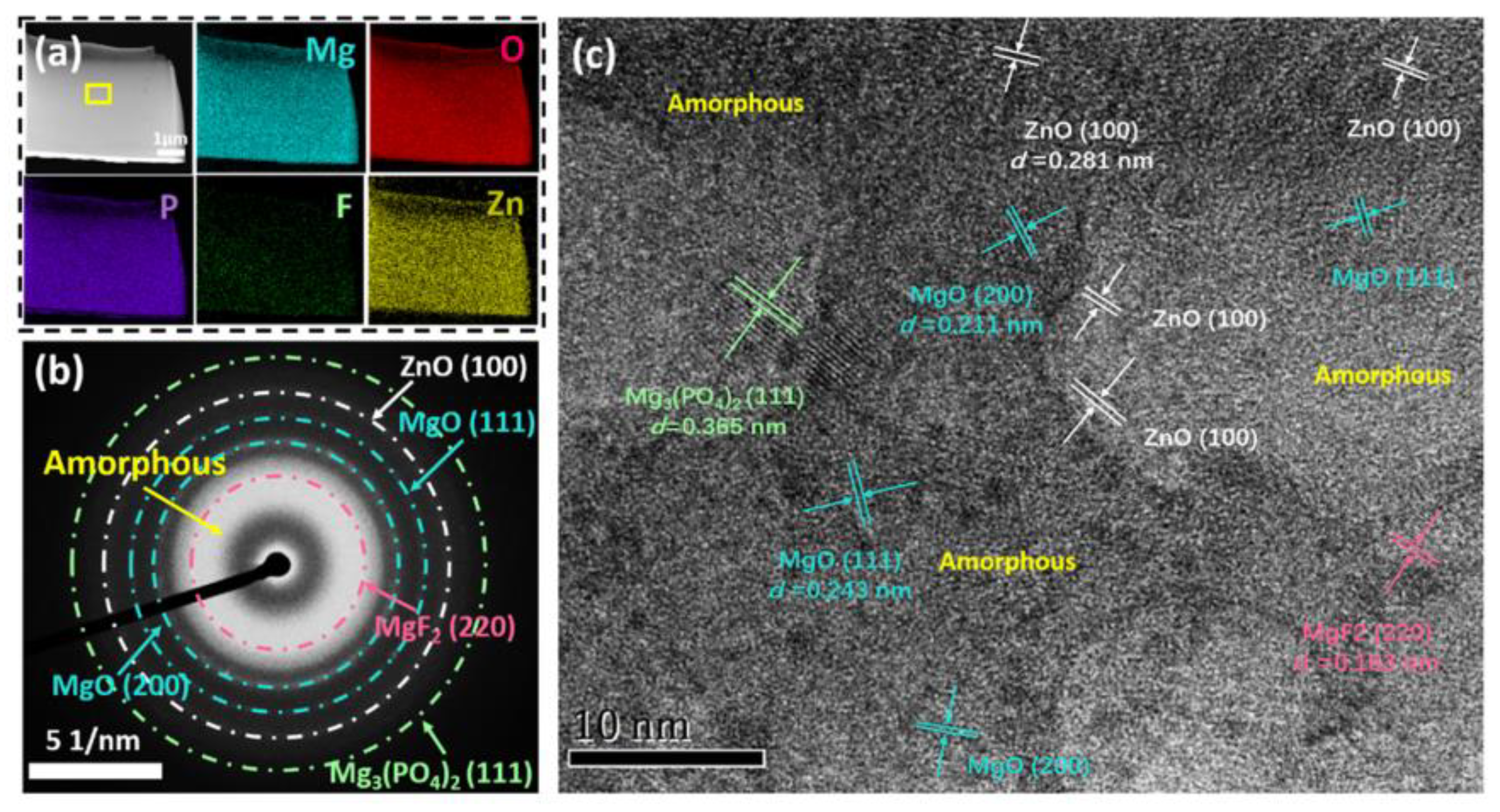
4.3. The Influence of Self-Growing Insoluble Phases on the Corrosion

The formation of self-growing insoluble phases more commonly uses phosphate as the electrolyte solution, primarily due to the fact that reactions in coatings prepared from silicates are more complex. This complexity leads to a lower content of corresponding silicates in the coating. Coatings containing only magnesium phosphate and magnesium oxide are not effective in providing corrosion resistance [13]. Therefore, it is essential to enhance the corrosion resistance of the coatings by adding other ions to form more insoluble phosphates or by reducing the surface content of MgO. By doing so, not only the structure of the coating is improved, but the onset of the first stage of corrosion is also delayed, ultimately enhancing the coating’s corrosion resistance. A commonly employed method is to add elements such as Ca and Zn to form a phosphate of low solubility constant on the surface, thereby increasing the coating’s density, as depicted in Figure 18 [48,54]. This technique effectively inhibits the corrosion of the coating. However, it is imperative to further improve the internal structure to address existing defects and stress-induced pitting. Electrochemical results indicate that PEO coatings doped with zinc phosphate exhibit exemplary corrosion resistance, as no noticeable pitting behavior was observed even after 4200 h of immersion in neutral salt spray, as shown in Figure 19 [48]. Given the specific requirement of an alkaline environment for the PEO electrolyte of Mg alloy, there are limited doping elements that can generate insoluble phosphate phases in situ. In the future, valuable insights and knowledge can be derived from these studies to further advance research in this area.
Additionally, the inclusion of aluminate in the phosphate system results in improved corrosion resistance. This is evidenced by a reduction in the MgO content within the coating and the increased formation of the insoluble compound MgAl2O4. Figure 20 illustrates that as the aluminum content rises, the ratio of MgO to Mg3(PO4)2 in the coating decreases. However, the variance in the Mg3(PO4)2 content is not considered to be significant [55].

5. Prospect

Over the past 30 years, research on corrosion-resistant PEO coatings on Mg alloy has made significant progress; however, there are still some issues in the theoretical research and application of PEO technology that need further improvement.
(1)
PEO mechanism. PEO technology is a complex and comprehensive technology that involves various disciplines such as chemistry, electrochemistry, plasma chemistry, and thermochemistry. While researchers have proposed some discharge processes and film-forming mechanisms of PEO technology, there are limitations, and the specific discharge and film-forming processes of PEO still cannot be clearly explained. Therefore, it is necessary to analyze and improve the theoretical model of PEO from an energy perspective, combining thermodynamic and kinetic theories, as well as advanced spectroscopic methods, in order to better design corrosion-resistant coatings.
(2)
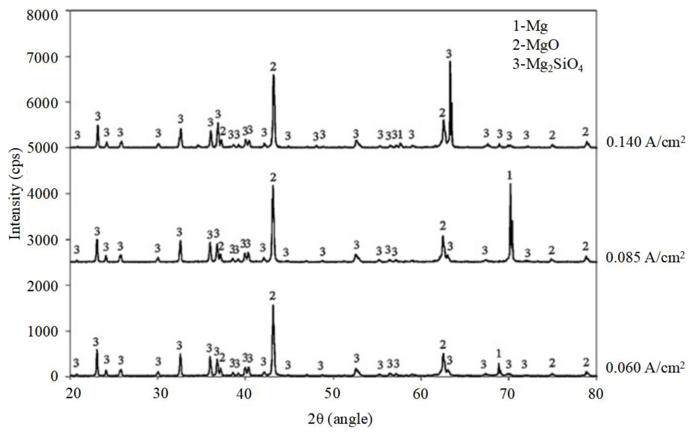
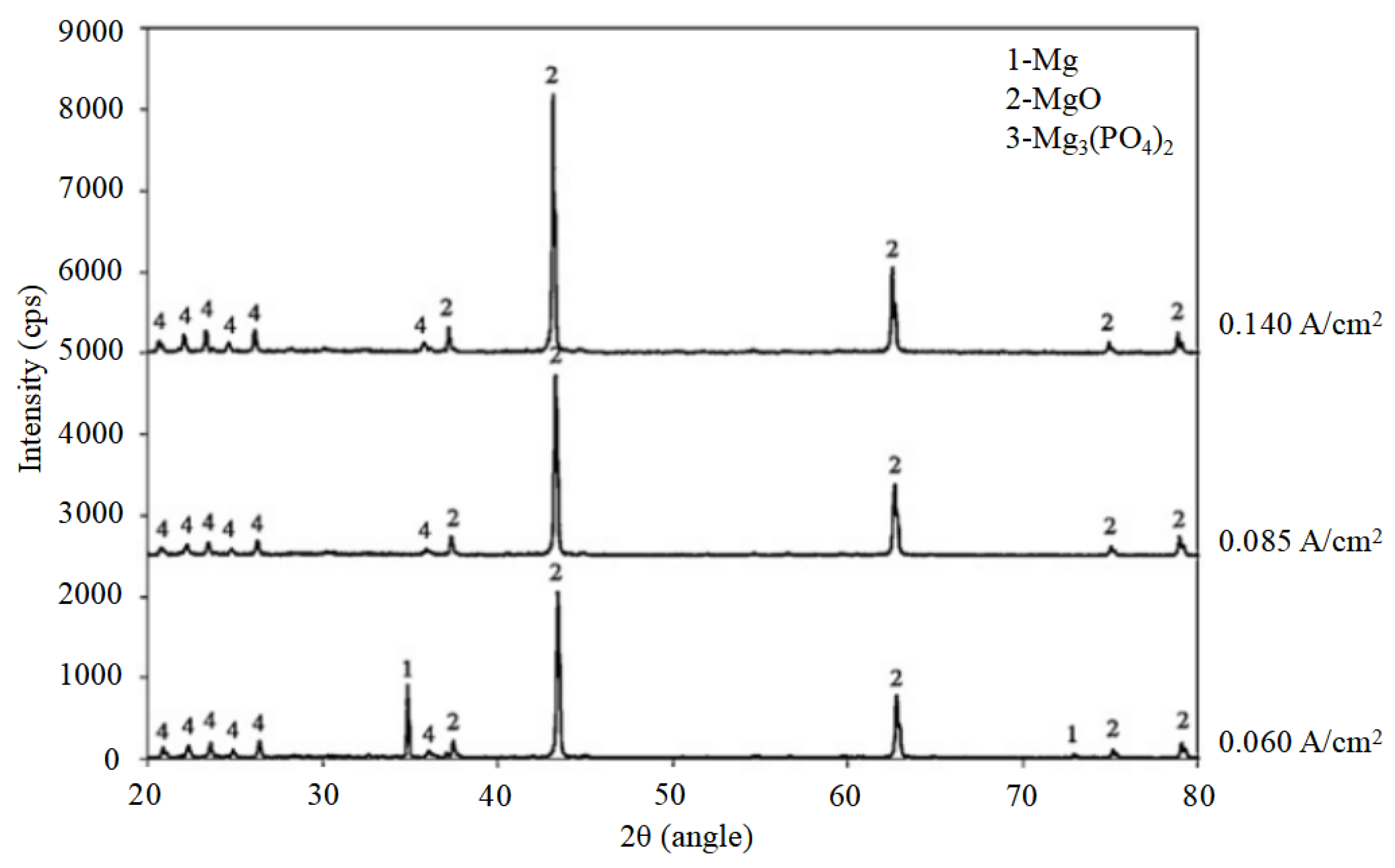
Electrolyte and electrical parameters. The selection of electrolyte directly affects the coating growth process on the Mg alloy. For example, phosphate system coatings grow inward, while silicate coatings maintain outward growth. Additives also affect the discharge process, resulting in coatings with different characteristics. The choice of electrical parameters affects the strength of discharge and the speed of film formation. Therefore, it is necessary to establish a large database of PEO coatings on Mg alloy and continuously share research theories and results of existing electrolytes and electrical parameters to improve the reference value of relevant data and refine more effective electrolyte systems for preparing corrosion-resistant coatings.
(3)
Power supply and energy consumption. Coatings prepared using bipolar pulse power sources are believed to be uniform and dense, resulting in optimal coating performance. Additionally, they can reduce the energy consumption of PEO processes. However, achieving uniform preparation of large samples is still a challenge, with the current maximum treatment area being only 4 m2. To meet the requirements of preparing uniform corrosion-resistant coatings on a large scale, it is necessary to design and develop an efficient, energy-saving, high-power power supply system suitable for large-area processing.
(4)
Strengthening of corrosion-resistant coatings. Various enhancement methods, including improving the crystallinity, density, thickness, roughness, micropores, and cracks of coatings, as well as the study of corrosion-resistant phases, are widely researched. There is relatively little research on the preparation of insoluble metal salts on Mg alloys, such as zinc phosphate and calcium phosphate, which have extremely low solubility product constants. It is necessary to uniformly mix these insoluble metal salts in PEO coatings on Mg alloys to significantly improve the corrosion resistance.

Author Contributions

Conceptualization, C.Y. and P.C.; methodology, W.W.; software, C.Y.; validation, C.Y., P.C. and L.S.; formal analysis, Y.Z. and W.W.; investigation, P.C. and W.W.; resources, C.Y.; data curation, C.Y.; writing—original draft preparation, C.Y.; writing—review and editing, P.C. and P.K.C.; visualization, P.K.C.; supervision, L.S.; project administration, P.C.; funding acquisition, C.Y. All authors have read and agreed to the published version of the manuscript.

Funding

This study was financially supported by the National funded postdoctoral researcher program (grant No. GZC20231545) and the China Postdoctoral Science Foundation (grant No. 2023M742224).

Informed Consent Statement

Not applicable.

Data Availability Statement

Data are contained within the article.

Conflicts of Interest

The authors declare no conflicts of interest.

References

  1. Parande, G.; Manakari, V.; Sharma Kopparthy, S.D.; Gupta, M. A study on the effect of low-cost eggshell reinforcement on the immersion, damping and mechanical properties of Mg–zinc alloy. Compos. Part B Eng. 2020, 182, 107650. [Google Scholar] [CrossRef]
  2. Srikanth, N.; Zhong, X.L.; Gupta, M. Enhancing damping of pure Mg using nano-size alumina particulates Materials. Letters 2005, 59, 3851–3855. [Google Scholar]
  3. Hamid, Z.A.; El-khair, M.T.A.; Hassan, H.B. Synthesis and protection of AM50 Mg alloy and its composites using environmentally pretreatment electrolyte. Surf. Coat. Technol. 2011, 206, 1041–1050. [Google Scholar] [CrossRef]
  4. Shao, Z.; Cai, Z.; Hu, R.; Wei, S. The study of electroless nickel plating directly on Mg alloy. Surf. Coat. Technol. 2014, 249, 42–47. [Google Scholar] [CrossRef]
  5. Ji, R.; Peng, G.; Zhang, S.; Li, Z.; Li, J.; Fang, T.; Zhang, Z.; Wang, Y.; He, Y.; Wu, J. The fabrication of a CeO2 coating via cathode plasma electrolytic deposition for the corrosion resistance of AZ31 Mg alloy. Ceram. Int. 2018, 44, 19885–19891. [Google Scholar] [CrossRef]
  6. Ono, S.; Moronuki, S.; Mori, Y.; Koshi, A.; Liao, J.; Asoh, H. Effect of Electrolyte Concentration on the Structure and Corrosion Resistance of Anodic Films Formed on Mg through Plasma Electrolytic Oxidation. Electrochim. Acta 2017, 240, 415–423. [Google Scholar] [CrossRef]
  7. Kuo, Y.-L.; Chang, K.-H. Atmospheric pressure plasma enhanced chemical vapor deposition of SiOx films for improved corrosion resistant properties of AZ31 Mg alloys. Surf. Coat. Technol. 2015, 283, 194–200. [Google Scholar] [CrossRef]
  8. Saei, E.; Ramezanzadeh, B.; Amini, R.; Kalajahi, M.S. Effects of combined organic and inorganic corrosion inhibitors on the nanostructure cerium based conversion coating performance on AZ31 Mg alloy: Morphological and corrosion studies. Corros. Sci. 2017, 127, 186–200. [Google Scholar] [CrossRef]
  9. Huang, Q.; Liu, L.; Wu, Z.; Ji, S.; Chu, P.K. Corrosion-resistant plasma electrolytic oxidation coating modified by Zinc phosphate and self-healing mechanism in the salt-spray environment. Surf. Coat. Technol. 2020, 384, 125321. [Google Scholar] [CrossRef]
  10. Luo, D.; Liu, Y.; Yin, X.; Wang, H.; Han, Z.; Ren, L. Corrosion inhibition of hydrophobic coatings fabricated by micro-arc oxidation on an extruded Mge5Sne1Zn alloy substrate. J. Alloys Compd. 2018, 731, 731–738. [Google Scholar] [CrossRef]
  11. Li, Z.; Ren, Q.; Wang, X.; Kuang, Q.; Ji, D.; Yuan, R.; Jing, X. Effect of phosphate additive on the morphology and anti-corrosion performance of plasma electrolytic oxidation coatings on Mg-lithium alloy. Corros. Sci. 2019, 157, 295–304. [Google Scholar] [CrossRef]
  12. Verdier, S.; Boinet, M.; Maximovitch, S.; Dalard, F. Formation, structure and composition of anodic films on AM60 Mg alloy obtained by DC plasma anodizing. Corros. Sci. 2005, 47, 1429–1444. [Google Scholar] [CrossRef]
  13. Durdu, S.; Aytaç, A.; Usta, M. Characterization and corrosion behavior of ceramic coating on Mg by micro-arc oxidation. J. Alloys Compd. 2011, 509, 8601–8606. [Google Scholar] [CrossRef]
  14. Liu, X.Y.; Luan, B.L. Corrosion and wear properties of PEO coatings formed on AM60B alloy in NaAlO2 electrolytes. Appl. Surf. Sci. 2011, 257, 9135–9141. [Google Scholar] [CrossRef]
  15. Duan, H.; Yan, C.; Wang, F. Effect of electrolyte additives on performance of plasma electrolytic oxidation films formed on Mg alloy AZ91D. Electrochim. Acta 2007, 52, 3785–3793. [Google Scholar] [CrossRef]
  16. Gu, Y.; Bandopadhyay, S.; Chen, C.-F.; Guo, Y.; Ning, C. Effect of oxidation time on the corrosion behavior of micro-arc oxidation produced AZ31 Mg alloys in simulated body fluid. J. Alloys Compd. 2012, 543, 109–117. [Google Scholar] [CrossRef]
  17. Zhang, X.; Zhang, Y.; Lv, Y.; Dong, Z.; Hashimoto, T.; Zhou, X. Enhanced corrosion resistance of AZ31 Mg alloy by one-step formation of PEO/Mg-Al LDH composite coating. Corros. Commun. 2022, 6, 67–83. [Google Scholar] [CrossRef]
  18. Guo, H.X.; Ying, M.A.; Wang, J.S.; Wang, Y.S.; Hao, Y. Corrosion behavior of micro-arc oxidation coating on AZ91D Mg alloy in NaCl solutions with different concentrations. Trans. Nonferrous Met. Soc. China 2012, 22, 1786–1793. [Google Scholar] [CrossRef]
  19. Liang, J.; Srinivasan, P.B.; Blawert, C.; Störmer, M.; Dietzel, W. Electrochemical corrosion behaviour of plasma electrolytic oxidation coatings on AM50 Mg alloy formed in silicate and phosphate based electrolytes. Electrochim. Acta 2009, 54, 3842–3850. [Google Scholar] [CrossRef]
  20. Hussein, R.; Northwood, D.; Nie, X. Processing-Microstructure Relationships in the Plasma Electrolytic Oxidation (PEO) Coating of a Magnesium Alloy. Mater. Sci. Appl. 2014, 5, 124–139. [Google Scholar] [CrossRef]
  21. Dehnavi, V.; Binns, W.J.; Noël, J.J.; Shoesmith, D.W.; Luan, B.L. Growth behaviour of low-energy plasma electrolytic oxidation coatings on a Magnesium alloy. J. Magnes. Alloys 2018, 6, 229–237. [Google Scholar] [CrossRef]
  22. Hussein, R.O.; Nie, X.; Northwood, D.O. A Yerokhin and A Matthews, Spectroscopic study of electrolytic plasma and discharging behaviour during the plasma electrolytic oxidation (PEO) process. J. Phys. D Appl. Phys. 2010, 43, 105203. [Google Scholar] [CrossRef]
  23. Krishna, L.R.; Poshal, G.; Jyothirmayi, A.; Sundararajan, G. Relative hardness and corrosion behavior of micro arc oxidation coatings deposited on binary and ternary Mg alloys. Mater. Des. 2015, 77, 6–14. [Google Scholar] [CrossRef]
  24. Rapheal, G.; Kumar, S.; Scharnagl, N.; Blawert, C. Effect of current density on the microstructure and corrosion properties of plasma electrolytic oxidation (PEO) coatings on AM50 Mg alloy produced in an electrolyte containing clay additives. Surf. Coat. Technol. 2016, 289, 150–164. [Google Scholar] [CrossRef]
  25. Wu, D.; Liu, X.; Lu, K.; Zhang, Y.; Wang, H. Influence of C3H8O3 in the electrolyte on characteristics and corrosion resistance of the microarc oxidation coatings formed on AZ91D Mg alloy surface. Appl. Surf. Sci. 2009, 255, 7115–7120. [Google Scholar] [CrossRef]
  26. Kazanski, B.; Kossenko, A.; Zinigrad, M.; Lugovskoy, A. Fluoride ions as modifiers of the oxide layer produced by plasma electrolytic oxidation on AZ91D Mg alloy. Appl. Surf. Sci. 2013, 287, 461–466. [Google Scholar] [CrossRef]
  27. Liu, F.; Shan, D.; Song, Y.; Han, E.-H. Effect of additives on the properties of plasma electrolytic oxidation coatings formed on AM50 Mg alloy in electrolytes containing K2ZrF6. Surf. Coat. Technol. 2011, 206, 455–463. [Google Scholar] [CrossRef]
  28. Yoo, B.; Shin, K.R.; Hwang, D.Y.; Dong, H.L.; Dong, H.S. Effect of surface roughness on leakage current and corrosion resistance of oxide layer on AZ91 Mg alloy prepared by plasma electrolytic oxidation. Appl. Surf. Sci. 2010, 256, 6667–6672. [Google Scholar] [CrossRef]
  29. Yang, C.; Sheng, L.Y.; Zhao, C.C.; Wu, D.; Zheng, Y.F. Regulating the ablation of nanoparticle-doped MAO coating on Mg alloy by MgF2 passivation layer construction. Mater. Lett. 2024, 355, 135559. [Google Scholar] [CrossRef]
  30. Chen, D.; Wang, R.; Huang, Z.; Wu, Y.; Zhang, Y.; Wu, G.; Li, D.; Guo, C.; Jiang, G.; Yu, S.; et al. Evolution processes of the corrosion behavior and structural characteristics of plasma electrolytic oxidation coatings on AZ31 Mg alloy. Appl. Surf. Sci. 2018, 434, 326–335. [Google Scholar] [CrossRef]
  31. Lee, S.-J.; Do, L.H.T. Effects of copper additive on micro-arc oxidation coating of LZ91 Mg-lithium alloy. Surf. Coat. Technol. 2016, 307, 781–789. [Google Scholar] [CrossRef]
  32. Han, H.; Wang, R.; Wu, Y.; Zhang, X.; Wang, D.; Yang, Z.; Su, Y.; Shen, D.; Nash, P. An investigation of plasma electrolytic oxidation coatings on crevice surface of AZ31 Mg alloy. J. Alloys Compd. 2019, 811, 152010. [Google Scholar] [CrossRef]
  33. Zhao, J.; Xie, X.; Zhang, C. Effect of the Graphene Oxide Additive on the Corrosion Resistance of the Plasma Electrolytic Oxidation Coating of the AZ31 Mg Alloy. Corros. Sci. 2016, 114, 146–155. [Google Scholar] [CrossRef]
  34. Tran, Q.-P.; Chin, T.-S.; Kuo, Y.-C.; Jin, C.-X.; Trung, T.; Tuan, C.V.; Dang, D.Q. Diamond powder incorporated oxide layers formed on 6061 Al alloy by plasma electrolytic oxidation. J. Alloys Compd. 2018, 751, 289–298. [Google Scholar] [CrossRef]
  35. Liu, X.H.; Liu, L.; Dong, S.; Chen, X.B.; Dong, J.B. Towards dense corrosion-resistant plasma electrolytic oxidation coating on Mg-Gd-Y-Zr alloy by using ultra-high frequency pulse current. Surf. Coat. Technol. 2022, 447, 128881. [Google Scholar] [CrossRef]
  36. Chen, W.-W.; Wang, Z.-X.; Sun, L.; Lu, S. Research of growth mechanism of ceramic coatings fabricated by micro-arc oxidation on Mg alloys at high current mode. J. Magnes. Alloys 2015, 3, 253–257. [Google Scholar] [CrossRef]
  37. Dou, J.; Wang, C.; Gu, G.; Chen, C. Formation of silicon-calcium-phosphate-containing coating on Mg-Zn-Ca alloy by a two-step micro-arc oxidation technique. Mater. Lett. 2018, 212, 37–40. [Google Scholar] [CrossRef]
  38. Cui, X.-J.; Liu, C.-H.; Yang, R.-S.; Li, M.-T.; Lin, X.-Z. Self-sealing micro-arc oxidation coating on AZ91D Mg alloy and its formation mechanism. Surf. Coat. Technol. 2015, 269, 228–237. [Google Scholar] [CrossRef]
  39. Yang, W.; Wang, J.; Xu, D.; Li, J.; Chen, T. Characterization and formation mechanism of grey micro-arc oxidation coatings on Mg alloy. Surf. Coat. Technol. 2015, 283, 281–285. [Google Scholar] [CrossRef]
  40. Liang, J.; Hu, L.; Hao, J. Improvement of corrosion properties of microarc oxidation coating on Mg alloy by optimizing current density parameters. Appl. Surf. Ence 2007, 253, 6939–6945. [Google Scholar] [CrossRef]
  41. Zhang, Y.; Wu, Y.; Chen, D.; Wang, R.; Li, D.; Guo, C.; Jiang, G.; Shen, D.; Yu, S.; Nash, P. Micro-structures and growth mechanisms of plasma electrolytic oxidation coatings on aluminium at different current densities. Surf. Coat. Technol. 2017, 321, 236–246. [Google Scholar] [CrossRef]
  42. Pezzato, L.; Rigon, M.; Martucci, A.; Brunelli, K.; Dabalà, M. Plasma Electrolytic Oxidation (PEO) as pre-treatment for sol-gel coating on aluminum and Mg alloys. Surf. Coat. Technol. 2019, 366, 114–123. [Google Scholar] [CrossRef]
  43. Srinivasan, P.B.; Blawert, C.; Dietzel, W. Effect of plasma electrolytic oxidation treatment on the corrosion and stress corrosion cracking behaviour of AM50 Mg alloy. Mater. Sci. Eng. A 2008, 494, 401–406. [Google Scholar] [CrossRef]
  44. Luo, H.; Cai, Q.; Wei, B.; Yu, B.; Li, D.; He, J.; Liu, Z. Effect of (NaPO3)6 concentrations on corrosion resistance of plasma electrolytic oxidation coatings formed on AZ91D Mg alloy. J. Alloys Compd. 2008, 464, 537–543. [Google Scholar] [CrossRef]
  45. Li, S.; Wu, Y.; Yamamura, K.; Nomura, M.; Fujii, T. Improving the grindability of titanium alloy Ti–6Al–4V with the assistance of ultrasonic vibration and plasma electrolytic oxidation. CIRP Ann.—Manuf. Technol. 2017, 66, 345–348. [Google Scholar] [CrossRef]
  46. An, L.; Ma, Y.; Liu, Y.; Sun, L.; Wang, S.; Wang, Z. Effects of additives, voltage and their interactions on PEO coatings formed on Mg alloys. Surf. Coat. Technol. 2018, 354, 226–235. [Google Scholar] [CrossRef]
  47. Liang, J.; Hu, L.; Hao, J. Characterization of microarc oxidation coatings formed on AM60B Mg alloy in silicate and phosphate electrolytes. Appl. Surf. Sci. 2007, 253, 4490–4496. [Google Scholar] [CrossRef]
  48. Zeng, R.-C.; Hu, Y.; Zhang, F.; Huang, Y.-D.; Wang, Z.-L.; Li, S.-Q.; Han, E.-H. Corrosion resistance of cerium-doped zinc calcium phosphate chemical conversion coatings on AZ31 Mg alloy. Trans. Nonferrous Met. Soc. China 2016, 26, 472–483. [Google Scholar] [CrossRef]
  49. Li, H.; Lu, S.; Qin, W.; Wu, X. In-situ grown MgO-ZnO ceramic coating with high thermal emittance on Mg alloy by plasma electrolytic oxidation. Acta Astronaut. 2017, 136, 230–235. [Google Scholar] [CrossRef]
  50. Qin, W.; Li, H.; Lu, S.; Wu, X. Influence of Zr4+ ions on solar absorbance and emissivity of coatings formed on AZ31 Mg alloy by plasma electrolytic oxidation. Surf. Coat. Technol. 2015, 269, 220–227. [Google Scholar]
  51. Tu, W.; Cheng, Y.; Wang, X.; Zhan, T.; Han, J.; Cheng, Y. Plasma electrolytic oxidation of AZ31 Mg alloy in aluminate-tungstate electrolytes and the coating formation mechanism. J. Alloys Compd. 2017, 725, 199–216. [Google Scholar] [CrossRef]
  52. Lu, X.; Blawert, C.; Mohedano, M.; Scharnagl, N.; Zheludkevich, M.L.; Kainer, K.U. Influence of electrical parameters on particle uptake during plasma electrolytic oxidation processing of AM50 Mg alloy. Surf. Coat. Technol. 2016, 289, 179–185. [Google Scholar] [CrossRef]
  53. Yang, C.; Huang, J.; Cui, S.; Fu, R.; Sheng, L.; Xu, D.; Tian, X.; Zheng, Y.; Chu, P.K.; Wu, Z.Z. NaF assisted preparation and the improved corrosion resistance of high content ZnO doped plasma electrolytic oxidation coating on AZ31B alloy. J. Magnes. Alloys, 2023; in press. [Google Scholar] [CrossRef]
  54. Yang, C.; Cai, H.; Cui, S.H.; Huang, J.; Zhu, J.Y.; Wu, Z.C.; Ma, Z.Y.; Fu, R.K.Y.; Sheng, L.Y.; Tian, X.B.; et al. A zinc-doped coating prepared on the Mg alloy by plasma electrolytic oxidation for corrosion protection. Surf. Coat. Technol. 2022, 433, 128148. [Google Scholar] [CrossRef]
  55. Liang, J.; Guo, B.; Tian, J.; Liu, H.; Zhou, J.; Liu, W.; Xu, T. Effects of NaAlO2 on structure and corrosion resistance of microarc oxidation coatings formed on AM60B Mg alloy in phosphate–KOH electrolyte. Surf. Coat. Technol. 2005, 199, 121–126. [Google Scholar] [CrossRef]
Figure 1. V-T diagram of the PEO process on Mg alloy: (a) silicate (red dotted line) and (b) silicate and phosphate mixing system (blue dotted line) [11] (Reprinted/adapted with permission from Elsevier, 2019).
Coatings 14 00451 g001
Figure 2. Surface arc discharge images of the PEO process on Mg alloy: (a) 10 s, (b) 60 s, (c) 150 s, (d) 300 s, and (e) 500 s [12] (Reprinted/adapted with permission from Elsevier, 2005).
Coatings 14 00451 g002
Figure 3. XRD of PEO coating prepared by silicate electrolyte [13] (Reprinted/adapted with permission from Elsevier, 2011).
Coatings 14 00451 g003
Figure 4. XRD of PEO coating prepared by phosphate electrolyte [13] (Reprinted/adapted with permission from Elsevier, 2011).
Coatings 14 00451 g004
Figure 5. A physical model of the corrosion process of PEO-coated AZ31 alloy immersed in the SBF with equivalent circuits for fitting EIS data: (a) R(Q(R(QR))), (b) R(Q(R(Q(R(QR))))), (c) R(Q(R(Q(R(QR))))), and (d) R(Q(R(QR))) [16] (Reprinted/adapted with permission from Elsevier, 2012).
Coatings 14 00451 g005
Figure 6. Schematic diagrams of the corrosion process of (a) PEO coating corrosion failure and (b) Zn-doped PEO coating without corrosion failure [9] (Reprinted/adapted with permission from Elsevier, 2020).
Coatings 14 00451 g006
Figure 7. Schematic representation of the corrosion process of PEO-coated specimens upon immersion for 50 h in a 0.1 M NaCl solution: (a) Si-PEO coating and (b) P-PEO coating [19] (Reprinted/adapted with permission from Elsevier, 2009).
Coatings 14 00451 g007
Figure 8. Schematic diagram of the PEO discharge model on the Mg alloy: (a) types A,B, and C discharges; (b) cross-sectional SEM image of the coating by type B discharge; and (c) XRD of the coating by type B discharge [20].
Coatings 14 00451 g008
Figure 9. The corresponding pore positions of discharge in types A and C [21].
Coatings 14 00451 g009
Figure 10. Tafel curves of oxide layers on AZ91 Mg alloys with different surface roughnesses [28] (Reprinted/adapted with permission from Elsevier, 2010).
Coatings 14 00451 g010
Figure 11. EIS curve of coating prepared by silicate electrolyte at different reaction times: (a,b) Bode plots, (c,d) Nyquist plots, and (e,f) the equivalent circuits employed to fit the spectra [30] (Reprinted/adapted with permission from Elsevier, 2018).
Coatings 14 00451 g011
Figure 12. SEM images of (a,b) 0.5 kHz, (c,d) 5 kHz, (e,f) 10 kHz, and (g,h) 20 kHz [35] (Reprinted/adapted with permission from Elsevier, 2022).
Coatings 14 00451 g012
Figure 13. Surface morphology and the responding EDS analyses of PEO coatings produced using the first-step and two-step processes: CSA (ac), CSB-350 (df), CSB-400 (gi), and CSB-450 (jl) [37] (Reprinted/adapted with permission from Elsevier, 2018).
Coatings 14 00451 g013
Figure 14. Sealing of zirconia in PEO coating on Mg alloy: (a) plasma discharge process and (b) formation process and structure of coating [38] (Reprinted/adapted with permission from Elsevier, 2015).
Coatings 14 00451 g014
Figure 15. Schematic diagram of different current modes [40] (Reprinted/adapted with permission from Elsevier, 2007). (A) constant current density; (B) decaying freely current density in the later stages; (C) stepped decreasing of current density.
Coatings 14 00451 g015
Figure 16. SEM and EDS of coating prepared from alkaline silicate solution: (a,c,e) no phosphate and (b,d,f) with phosphate [11] (Reprinted/adapted with permission from Elsevier, 2019).
Coatings 14 00451 g016
Figure 17. TEM observation on the cross-section of the PEO coating doped with ZnO nanoparticles: (a) EDS mapping; (b) SAED pattern, and (c) HRTEM image showing the compound as nanocrystalline and amorphous [53].
Coatings 14 00451 g017
Figure 18. Schematic diagram of formation of calcium phosphate and zinc phosphate on Mg alloy: (a) dissolution of α-Mg matrix neighboring AlMn-phase and hydrogen release, (b) formation of the nucleus of cerium phosphate, (c) nuclei formation of magnesium phosphate, (d) formation of calcium phosphate, (e) formation of the zinc phosphate nucleus, and (f) coalescence of zinc phosphate nuclei and formation of crystalline zinc phosphate coating [54] (Reprinted/adapted with permission from Elsevier, 2022).
Coatings 14 00451 g018
Figure 19. EIS curves for the PEO coatings after different salt spraying times with a 5 wt% NaCl solution: (a) Zn-0, (b) Zn-5, (c) Zn-10, and (d) Zn-15 [48] (Reprinted/adapted with permission from Elsevier, 2016).
Coatings 14 00451 g019
Figure 20. XRD of PEO coating containing aluminate: (a) 0 g/L, (b) 2 g/L, and (c) 8 g/L [55] (Reprinted/adapted with permission from Elsevier, 2005).
Coatings 14 00451 g020
Disclaimer/Publisher’s Note: The statements, opinions and data contained in all publications are solely those of the individual author(s) and contributor(s) and not of MDPI and/or the editor(s). MDPI and/or the editor(s) disclaim responsibility for any injury to people or property resulting from any ideas, methods, instructions or products referred to in the content.

