Article

Tribological Properties of Hard TiB2 Thin Films Prepared at Low Temperatures Using HiPIMS

1
International Joint Institute of Advanced Coating Technology, Taizhou University, Taizhou 318000, China
2
Wenling Research Institute, Taizhou University, Taizhou 318000, China
3
Zhejiang Provincial Key Laboratory for Cutting Tools, Taizhou University, Taizhou 318000, China
4
Science and Technology on Surface Engineering Laboratory, Lanzhou Institute of Physics, Lanzhou 730000, China
5
Civil Aviation Department, Zhejiang Institute of Communication, Hangzhou 311112, China
*
Authors to whom correspondence should be addressed.
Coatings 2024, 14(4), 492; https://doi.org/10.3390/coatings14040492
Submission received: 19 March 2024 / Revised: 8 April 2024 / Accepted: 13 April 2024 / Published: 16 April 2024
(This article belongs to the Special Issue Nanostructured Films and Their Multi-scale Applications)

Abstract

:
Magnetron-sputtered WS2 composite thin films are solid lubricants with excellent performances. However, the low hardness of the WS2 thin films necessitates the further improvement of their wear resistance. For this purpose, an effective strategy is to alternately deposit or code posit WS2 and a hard phase, such as TiB2, to form hard lubricant thin films. Herein, a TiB2 thin film was prepared under the same conditions as those used for depositing the WS2 thin film with a dense structure and excellent tribological properties. Because of the high deposition energy of high-power impulse magnetron sputtering (HiPIMS), the TiB2 thin film possesses a dense structure and leather-like flat surface (hardness = 24.17 GPa). The friction coefficient of the film under different loads ranges between 0.6 and 0.8. The wear rate of the thin film increases with load, mainly because of fatigue wear and abrasive wear. Under high loads, obvious furrow-like wear marks are observed. At different sliding frequencies, except 8 Hz, the friction coefficient of the film ranges from 0.6 to 0.8. The main wear mode is fatigue wear, particularly at increasing sliding frequencies. Although the film possesses a relatively high friction coefficient, its wear resistance is excellent (minimum wear rate = 1.96 × 10⁻⁶ mm3/(N·m)).

1. Introduction

Mutual friction and wear in mechanical equipment inevitably shorten the service life of its components and cause significant energy losses [1,2]. Therefore, studying the tribological properties of materials is crucial to reduce their surface friction coefficient and wear. Self-lubricating composite films are receiving increasing attention because of their excellent wear resistance and low coefficient of friction (COF) [3].
As transition metal sulfides with a layered structure, magnetron-sputtered WS2 composite films are solid lubricant materials with satisfactory lubricating properties and stability [4]. However, pure WS2 films possess poor wear resistance because of their loose structure and low hardness. Generally, the wear resistance of WS2 films can be modified by doping with metal elements, such as Ti [5,6], Cr [7], Ni [8], and Al [9]. The addition of metal elements can effectively improve the hardness of WS2-based composite films. Additionally, by increasing the deposition energy, the density and hardness of the WS2 thin film can be increased, improving its wear resistance. Exploiting the high deposition energy of high-power impulse magnetron sputtering (HiPIMS), we prepared a pure WS2 solid lubricating film possessing a dense structure and excellent wear resistance at a low temperature of 100 °C. The relevant results are awaiting publication separately. However, the film hardness is generally only 6–7 GPa and is suitable for application under low loads. Therefore, the wear resistance of the film under high loads requires further improvement.
To improve the hardness of WS2-based composite films, an effective strategy is to alternately deposit or co-deposit WS2 and a hard metal nitride phase, such as TiSiN [10], TiN [11,12], or TiAlSiN [13], to form hard lubricant thin films. However, the preparation of metal nitride hard coatings often requires high temperatures. TiB2 exhibits substantially high hardness and satisfactory wear resistance [14,15,16,17] and is used for modifying WS2 films [18,19]. Duan [18] et al. prepared a hard WS2/TiB2 self-lubricating composite thin film by co-sputtering a WS2 target with a TiB2 target to mix the soft phase of WS2 with the hard phase of TiB2. The results reveal that the thin film possesses a hardness of >20 GPa and a low COF (~0.2), and it demonstrates excellent antifriction and wear performances in wet environments. Liu [19] et al. demonstrated that compared with pure WS2 films, the TiB2-doped WS2 composite thin films possess a dense amorphous structure with considerably improved oxidation resistance and mechanical properties. Moreover, hard-phase TiB2 imparted thin films with excellent wear resistance and lubrication properties during friction at high temperatures [10]. Research has shown that the process parameters of magnetron sputtering (pulse, peak current, deposition temperature, deposition air pressure, etc.) have a certain influence on the properties of TiB2 thin film [20]. Hellgren [21] et al. investigated that TiB2 films deposited by HiPIMS on substrates at 500 °C always showed low B/Ti stoichiometry (titanium-rich), while the lack of stoichiometry could be reduced by regulating the increase of the pulse and peak current density.
A WS2 solid lubricating film possessing a dense structure and excellent wear resistance was previously obtained at 100 °C using HiPIMS. Herein, a TiB2 thin film was prepared under the same conditions as those used for depositing the WS2 thin film. The microstructure, ingredient analysis, mechanical properties, and tribological properties of the deposited film were analyzed using scanning electron microscopy (SEM), X-ray Powder diffractometer (XRD), Nano-indentation and scratch testing, and tribometer. The results indicate that the TiB2 thin film deposited at low temperatures exhibits a dense structure and high hardness. Although its friction coefficient is substantially high, the as-prepared film exhibits a satisfactory wear resistance.

2. Materials and Methods

2.1. Preparation of the Film

The TiB2 thin film was prepared using HiPIMS technology by employing a pure Ti target (99.9% purity) and a TiB2 target. The experimental instrument is an ion arc/magnetron sputtering composite coating machine (Beijing Powertech Technology Co., Ltd., Beijing, China; SP-0806ASI). Argon (99.9% purity) was used as the working gas. Polished stainless steel sheets (20 mm × 20 mm × 2 mm) and single-crystal silicon wafer sheets (100) were used as substrates. These substrates were separately cleaned in acetone (purity 99.5%; Zhejiang Hannuo Chemical Technology Co., Ltd., Taizhou, China) and anhydrous ethanol (purity 99.5%; Shanghai Chemical Reagent General Factory, Shanghai, China) for 20 min using an ultrasonic cleaner. Before deposition, the background vacuum was pumped to 5 × 10⁻³ Pa, and the chamber temperature was increased to 100 °C. Thereafter, argon was introduced in the chamber to achieve a pressure of 0.8 Pa.
Afterward, an ion source was employed to further clean the substrate surface with a bias voltage of 400 V. The glow plasma cleaning time was 30 min. Before depositing the TiB2 thin film, a layer of the Ti film was pre-deposited to increase adhesion between the film and substrate. During Ti layer deposition, the power source voltage, current, pulse frequency, and pulse width of HiPIMS were 460 V, 25 A, 1000 Hz, and 100 µs, respectively. The substrate pulse bias, pulse width, and frequency were 50 V, 10 µs, and 75 kHz, respectively. The deposition time was 5 min. Subsequently, the TiB2 layer was deposited. The power voltage, current, pulse frequency, and pulse width of HiPIMS during TiB2 deposition were 580 V, 85 A, 1000 Hz, and 60 µs, respectively. The substrate pulse bias, pulse width, and frequency were 60 V, 10 µs, and 75 kHz, respectively. The deposition time was 60 min.

2.2. Structural, Compositional Characterization and Mechanical Properties of the Thin Film

SEM (Hitachi, Ltd., Tokyo, Japan, S-4800) was used to analyze the surface and cross-sectional morphologies of the TiB2 thin film deposited on silicon wafers. The silicon wafer coated with a thin film was divided into two halves with tweezers, and then the cross-sectional morphology was observed under SEM. The crystal structure of TiB2 was tested and analyzed by an X-ray diffractometer (Bruker Corporation, Bremen, Germany, D8 Advance), and the scanning speed was 5°/min, and the scanning range was 20°~85°. A NanoTest Vantage instrument (Micro Materials, Wrexham, UK, MML31CN) was employed to test the hardness (H) and elastic modulus (E) of the TiB2 thin film. During testing, the indentation load was set to 15 mN. The indentation depth was ensured to be less than one-tenth of the thickness of the thin film. Sixteen points were measured on the sample, and the average value was calculated.
Experiments were conducted to characterize the bonding strength between the TiB2 thin film and substrate using an automatic thin-film adhesion scratcher (Lanzhou Zhongke Kaihua Technology Development Co., Ltd., Lanzhou, China, WS-2005) and an optical microscope. Acoustic emission, dynamic load, and single reciprocation were adopted as the measurement method, operation mode, and reciprocation mode, respectively. The test load, loading rate, and scratch length were 40 N, 40 N/m, and 4 mm, respectively. Thereafter, optical microscopy was adopted to observe the scratch morphology to determine the critical loads of the three phases (LC1 and LC2) [22,23].

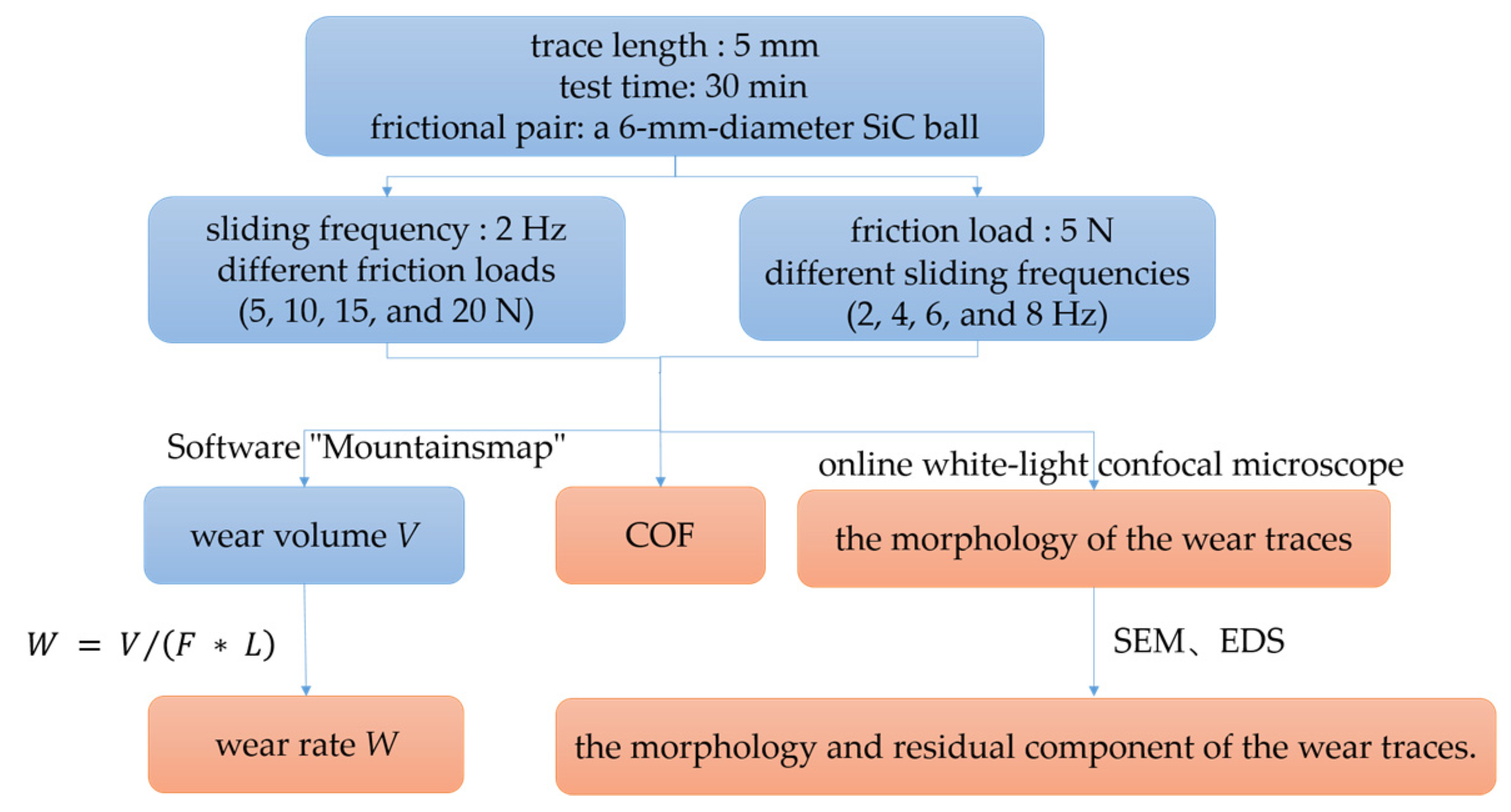
2.3. Tribological Properties of the Thin Film

The tribological properties of the TiB2 thin film were tested at room temperature using a multifunction tribometer (RTEC-Instruments Inc., Nanjing, China, MFT-5000) at different loads and sliding frequencies. A 6-mm-diameter SiC ball was employed as a frictional pair, and a linear reciprocating mode was adopted. The trace length and test time were 5 mm and 30 min, respectively.
COF can be obtained after the friction test using the software “MFT V22.3.28”. The morphologies of the wear traces were obtained using an In-line Lambda 3D optical profilometer mounted on an MFT-5000 multifunction tribometer. The wear volume V can be obtained by using the software “MountainsMap Imaging Topography V9.2”. The wear rate W was calculated using the following equation:
W = V / F × L ,
where W is the wear rate (mm3/(N·m)); V is the wear volume (mm3); F is the applied load (N); and L is the total sliding length (m).
Additionally, to analyze the wear mechanism, SEM and energy dispersive spectrometry (EDS) were used to characterize the morphology and residual component of the wear traces. Figure 1 illustrates a flow chart for TiB2 thin-film friction testing.

3. Results and Discussion

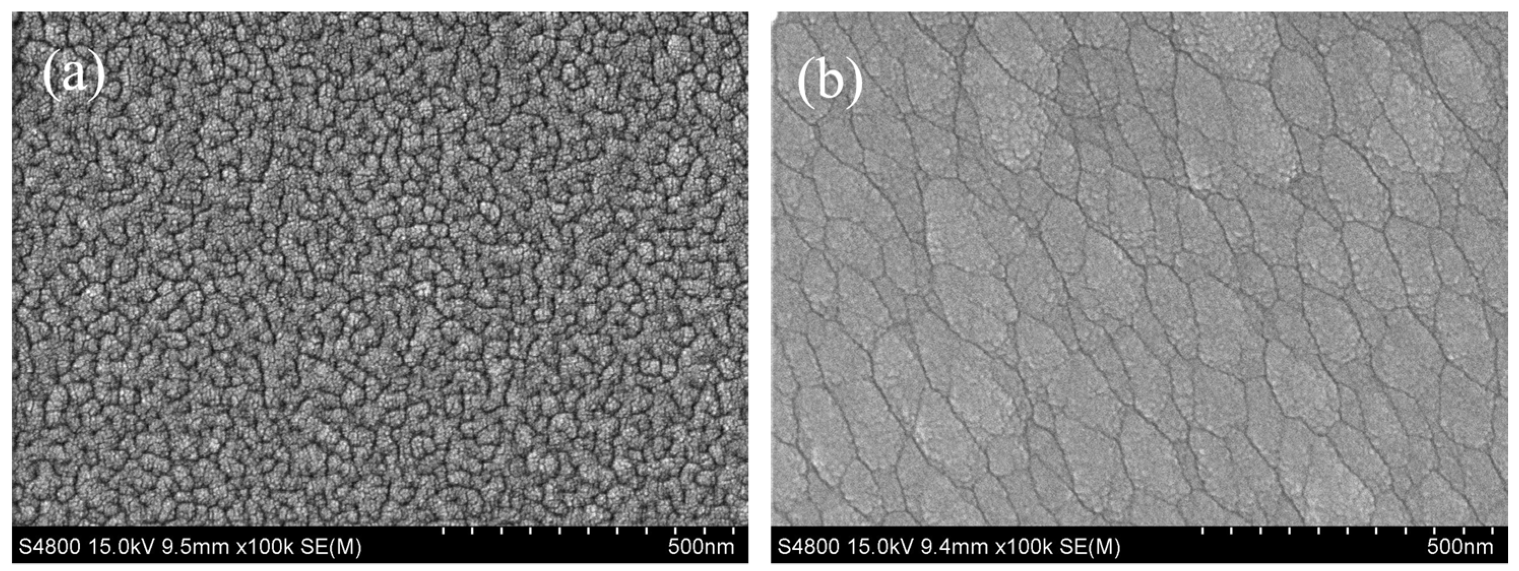
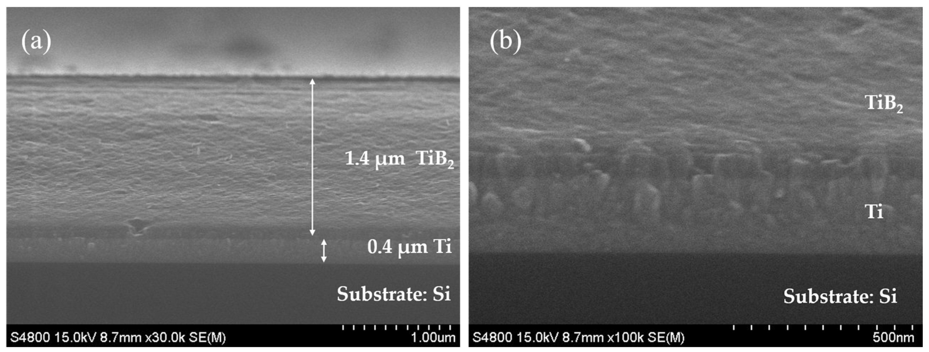
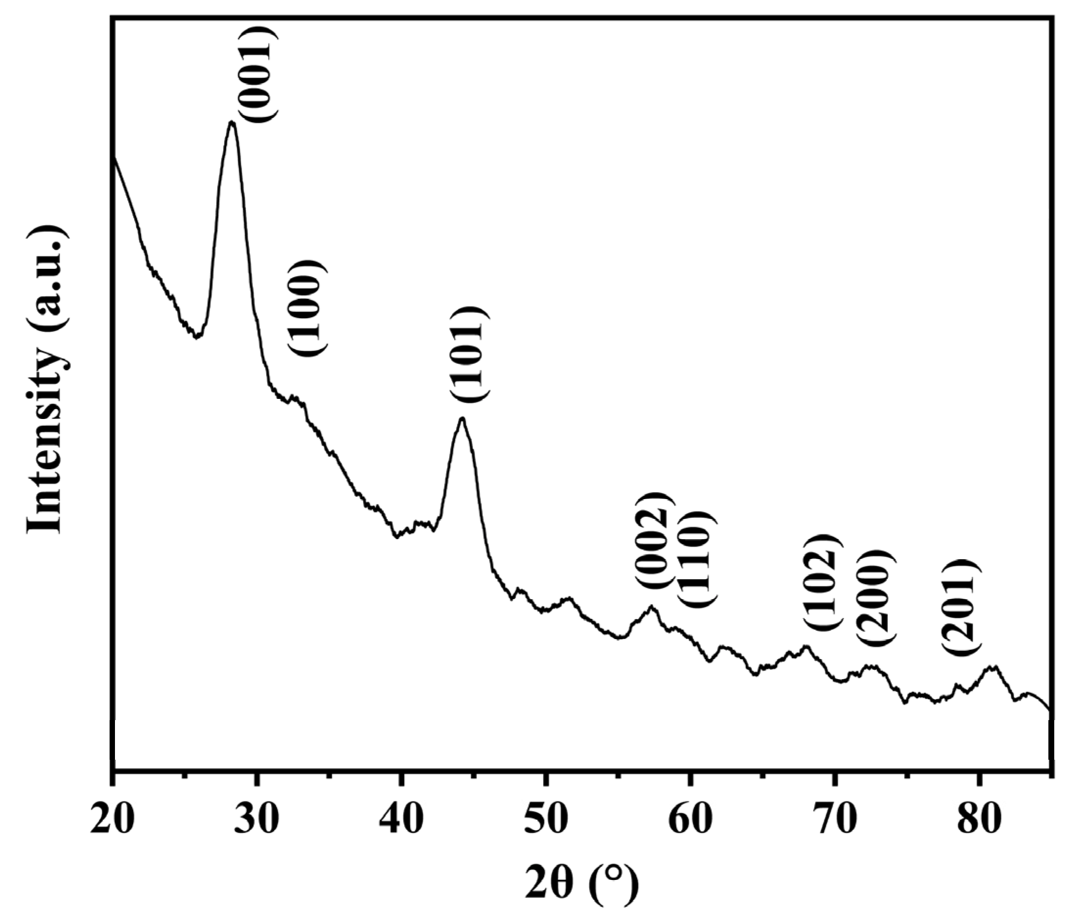
3.1. Morphological and Phase Analysis of the TiB2 Thin Film

Figure 2a,b presents the surface topographies of the Ti transition layer and TiB2 thin film deposited on a silicon substrate. As shown in the Figure, Ti thin film has a dense structure with very small and uniform grains. The TiB2 thin film surface exhibits a dense structure and satisfactory surface quality with no obvious defects; however, the grain size is not uniform. Figure 3a,b depicts the cross-sectional topography of the TiB2 thin film. The thin film exhibits layered deposition with a highly dense structure. HiPIMS has high deposition energy, so the deposited films always show layer growth and exhibit dense structures. The thicknesses of the TiB2 thin film and transition Ti layer are ~1.4 and 0.4 μm, respectively.
Figure 4 shows the XRD patterns of TiB2 thin film prepared using HiPIMS. It can be seen that the deposited film exhibits a crystal phase near 27°. This crystal orientation often appears in TiB2 thin films prepared using HiPIMS [21,24]. Meanwhile, strong diffraction peaks were also observed near 44°, corresponding to the (101) crystal phase of TiB2. In addition, as shown in the Figure, many diffraction peaks with low intensity also appeared. From the XRD result, it can be seen that the prepared TiB2 film is mainly composed of (001) and (101) crystal phases.

3.2. Mechanical Properties of the TiB2 Thin Film

The hardness (H) and approximate modulus of elasticity (E) of the TiB2 thin film were obtained using the NanoTest Vantage system (Table 1). The deposited film possesses a high hardness of 24.17 GPa. The approximate modulus of elasticity was 256.80 GPa, and H/E and H3/E2 values were calculated as 0.0941 and 0.2141, respectively. The results indicate that the deposited film exhibits a satisfactory ability to resist crack formation and propagation [25]. These findings imply that TiB2 thin films with high hardness and satisfactory mechanical properties can be prepared via HiPIMS at low temperatures.

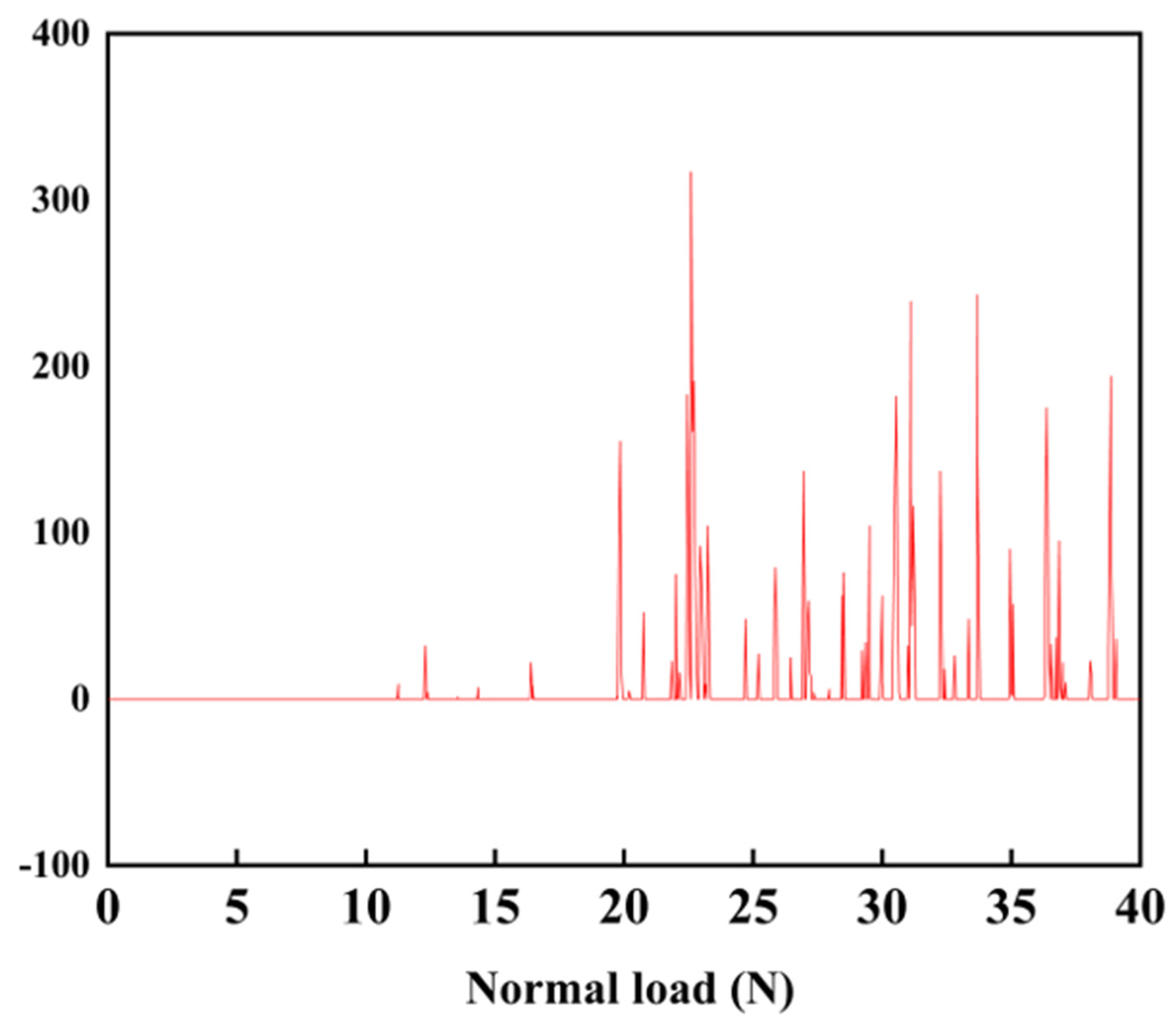
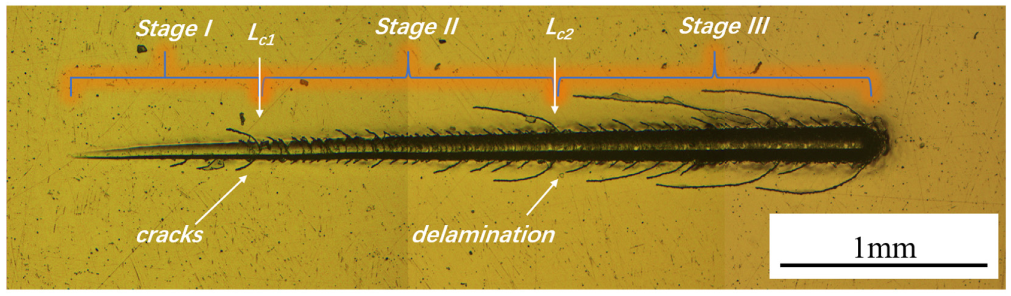
3.3. Analysis of the Bonding Force between the TiB2 Thin Film and Substrate

Figure 5 depicts the acoustic emission spectrum obtained during the scratch test of the TiB2 thin film. The acoustic emission peaks begin to appear at loads of approximately 13 and 17 N. However, the peaks at 13 and 17 N are substantially low, and the number of surrounding peaks is small. When the load exceeds 19.8 N, dense and high peaks begin to appear.
Figure 6 presents the scratch morphology and a partially enlarged view of the scratch morphology obtained using an optical microscope. The three stages (I, II, and III) of coating failure and the values of critical loads (LC1 and LC2) are clearly marked in the Figure. In stage I, the scratch is shallow, and only slight plastic deformation is present. In stage II, cracks appear in the scratch, and micro-cracks emerge on the surface of the film around the scratch. As the loading force increases, the scratch enters stage III, and more cracks form on the scratch. Simultaneously, long cracks appear on the surface of the film around the scratch, which is accompanied by the peeling off the film. Initially, some cracks were exhibited in stage II, and as the loading force increased, conformal cracking appeared in stage III. As the scratch load increases, buckling spallation initiates and intensifies [26,27]. When the loading force reaches near LC1, a long crack is observed on the thin-film surface, and a piece of the thin film peels off in stage I. The crack formation and the peeling of the surface layer of the film led to the appearance of sporadic peaks at approximately 13 and 17 N in the acoustic emission spectrum. However, the interior of the scratch remains flat, so the loading force has not yet reached the critical load at this point.
Based on Figure 5 and Figure 6, the critical load of the thin film, LC, can be concluded to be 19.8 N [28,29].

3.4. Tribological Properties of the TiB2 Thin Film

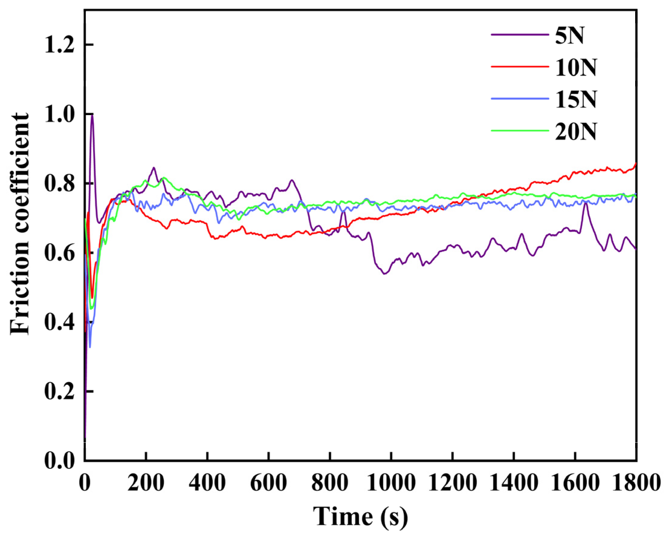
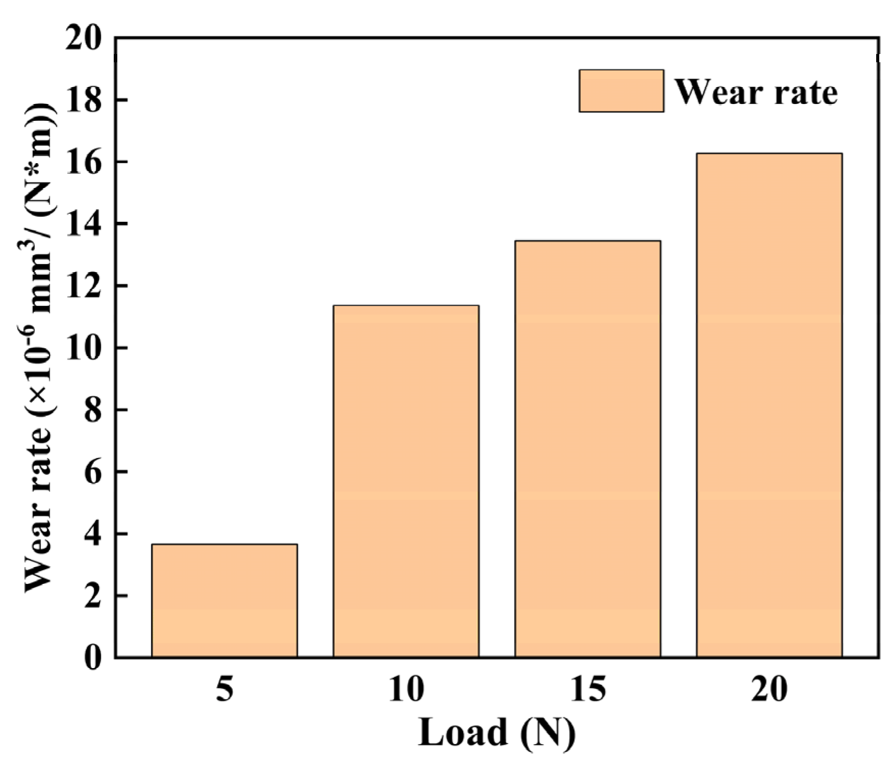
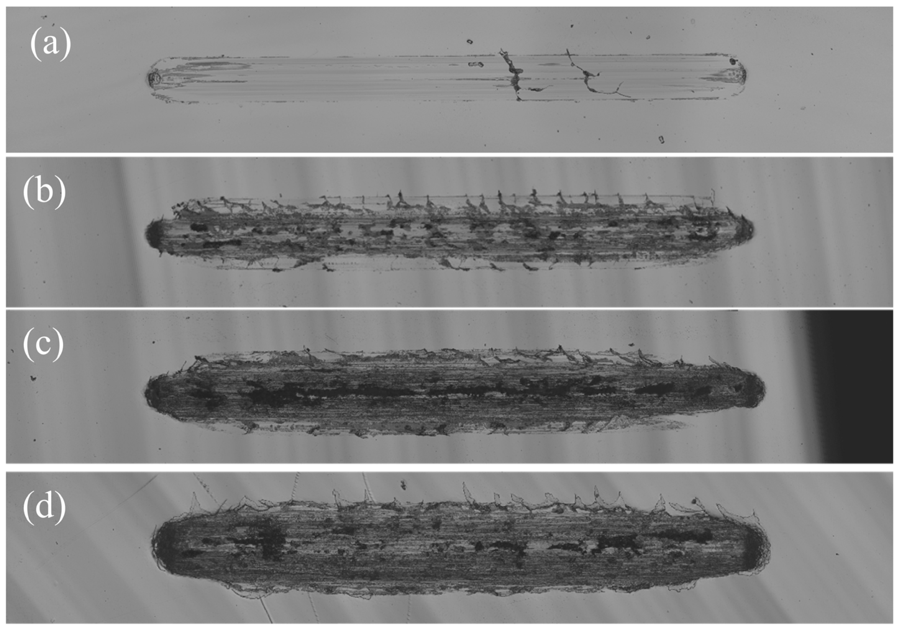
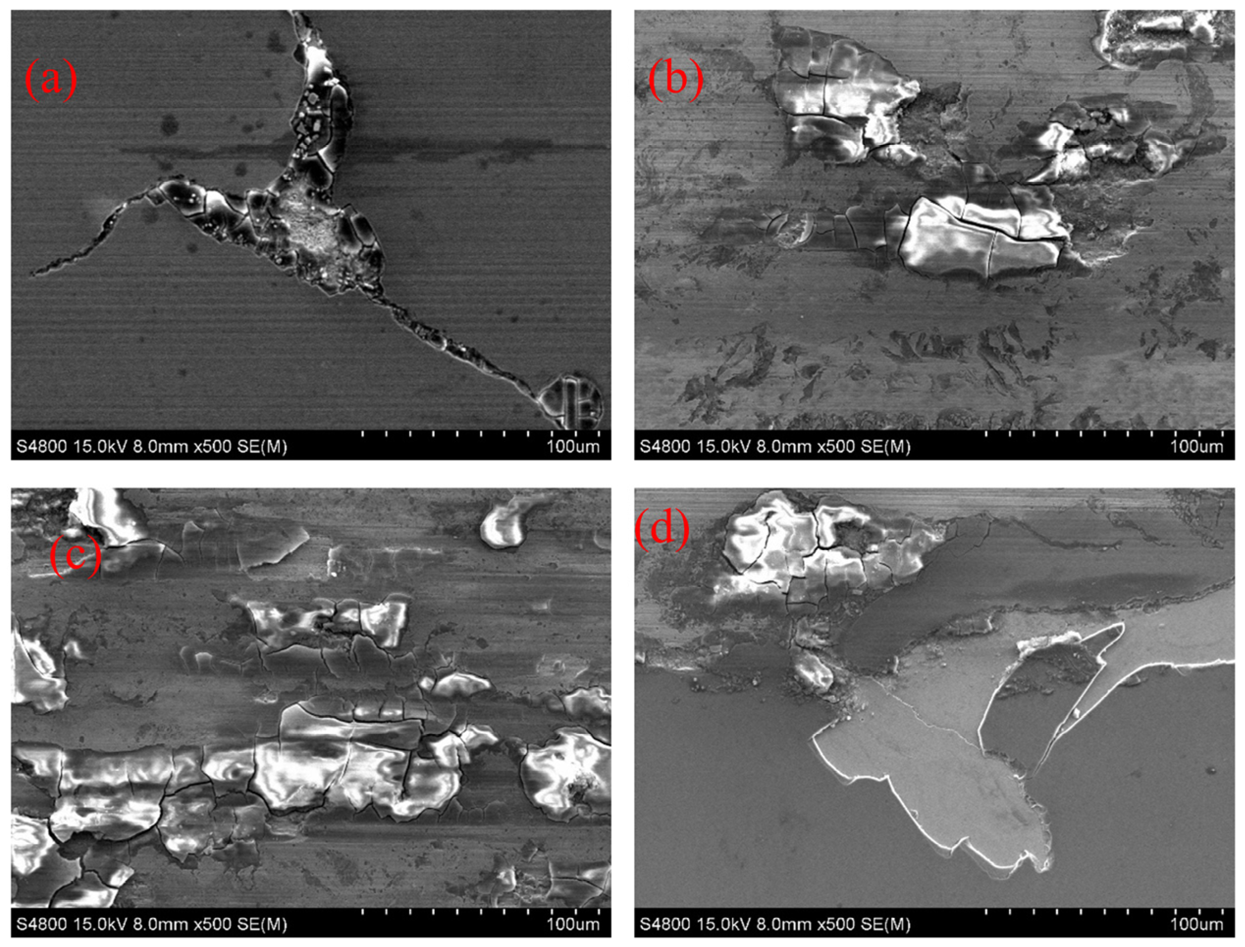
3.4.1. Tribological Properties of the TiB2 Thin Film under Different Loads

The tribological properties of the TiB2 thin film under different friction loads (5, 10, 15, and 20 N) were tested using a tribometer in the linear reciprocating mode. Figure 7 depicts the friction coefficient of the TiB2 thin film under different loads. Initially, significant fluctuations are observed in the friction coefficient, corresponding to the running stage of frictional wear. In the stable wear stage, the wear is slight, and the wear rate is stable. Overall, the friction coefficient of the thin film under different friction loads is approximately equivalent to 0.8. As a hard phase, the hardness of the TiB2 particles is very large. So, the particles are not easy to be smoothed out during the friction process and cause a large frictional resistance. Resulting in a high COF with zigzagging unevenness. When the load is 5 N, the friction coefficient decreases to ~0.6 after ~700 s. When the load is 10 N, the friction coefficient gradually increases from approximately 0.7. The friction coefficient is more stable under the loads of 15 and 20 N.
Table 2 and Figure 8 present the wear rates of the TiB2 thin film under different loads at a sliding frequency of 2 Hz. The wear volume and wear rate correspondingly increase with an increase in the friction load. At a load of 5 N, the minimum wear rate is 3.66 × 10⁻⁶ mm3/(N·m). The increase in the wear and wear rate may be related to the wear through the TiB2 thin film.
Figure 9 presents the morphology of the wear traces on the surface of the TiB2 thin film under different loads. At a load of 5 N, the wear trace was without any obvious defects except for two cracks. When the load is increased to 10 N, the wear marks become pronounced, and several micro-cracks appear. With increasing load, wear becomes more severe. Compared to the case under a load of 5 N, when the load is 20 N, the width of the wear scar increases by approximately two times, and the coating falls off, which is clearly observed using an optical microscope.
Figure 10 depicts the SEM images and EDS surface scanning analysis results of the local wear traces under different loads. Under a load of 5 N, a large amount of Ti remains on the surface of the wear trace. However, except in the crack, Fe was not detected. These results imply that the coating has not been worn thoroughly. When the load increases to 10, 15, and 20 N, the amount of Ti on the worn surface decreases, whereas the Fe content increases. These findings are consistent with the characterization results of the worn cross-section.
From the SEM images in Figure 10, with an increase in load, a significant increase in detachment is observed around the edge of the wear trace, and the detachment area increases. Based on the EDS results, TiB2 and Ti layers have peeled off together. This indicates that the wear failure of the thin film may be related to the poor adhesion of the Ti layer to the substrate. Figure 11 depicts a local magnification of the TiB2 thin-film abrasion at 500× obtained using SEM. Figure 11a demonstrates a structure in which the plow-shaped grooves produced by abrasive wear are present in the wear marks. Granular-like debris repeatedly scratches the surface during friction, leaving abrasion marks on the surface [30]. Figure 11d presents a local magnification of the edge of the wear traces with obvious peeling off the thin film, with the Ti layer and TiB2 thin film depicted in white and gray, respectively.

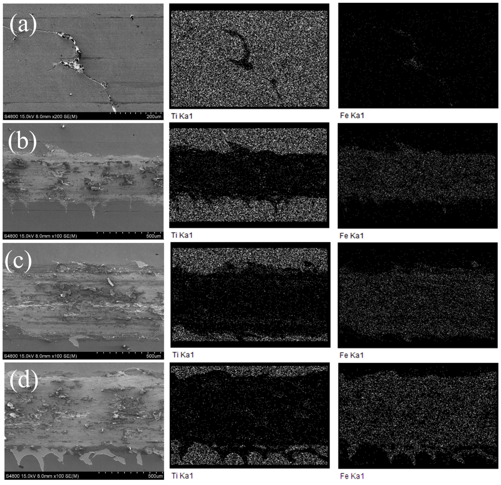
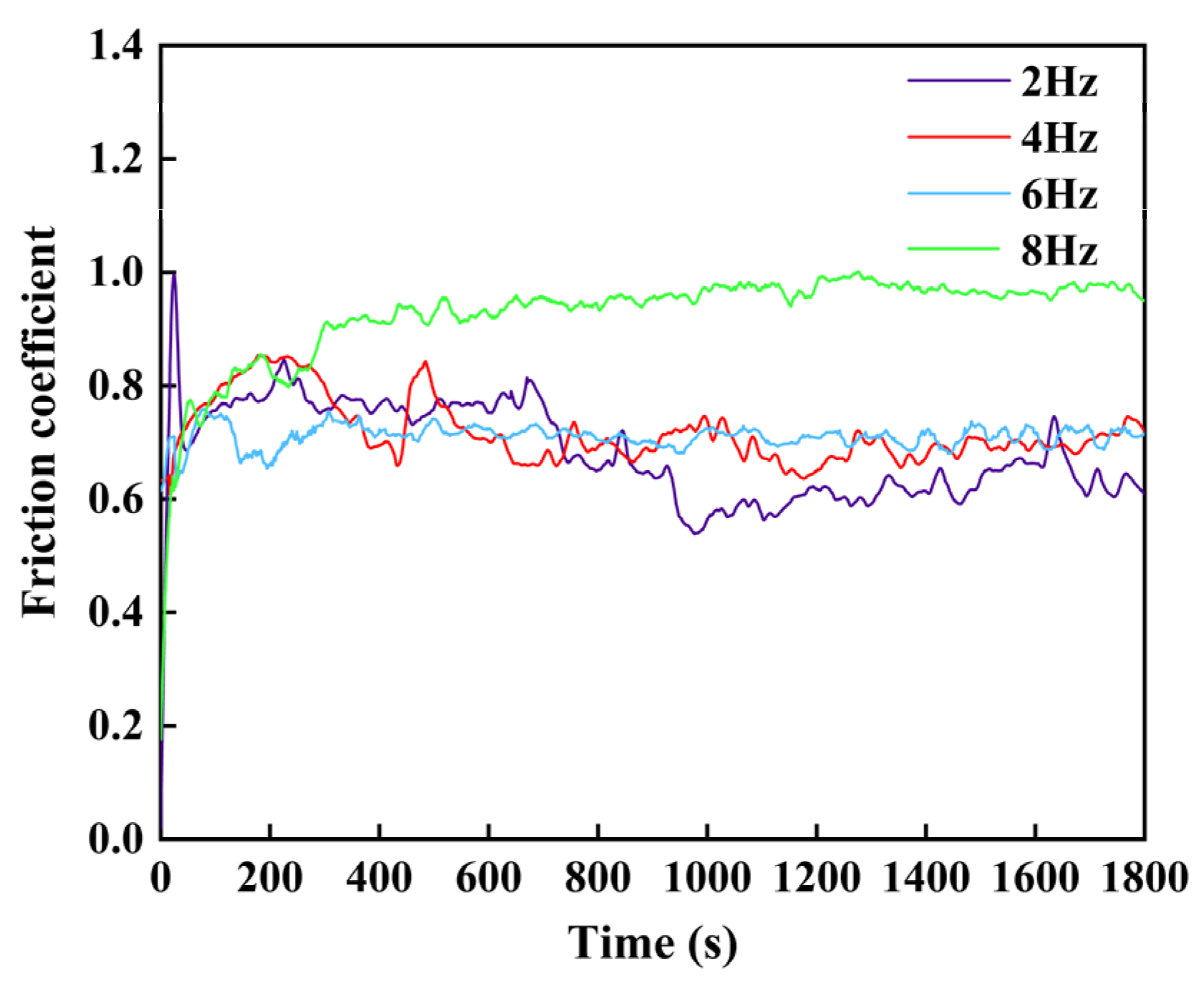
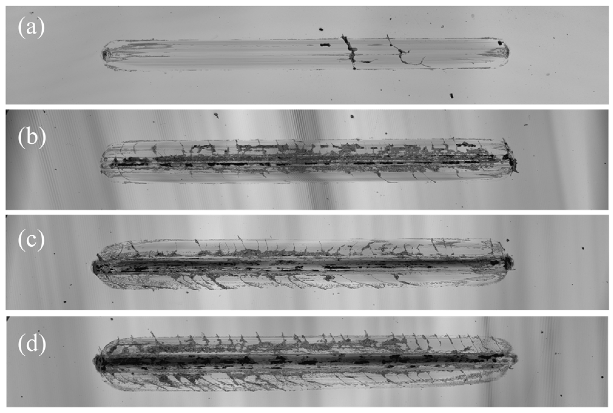
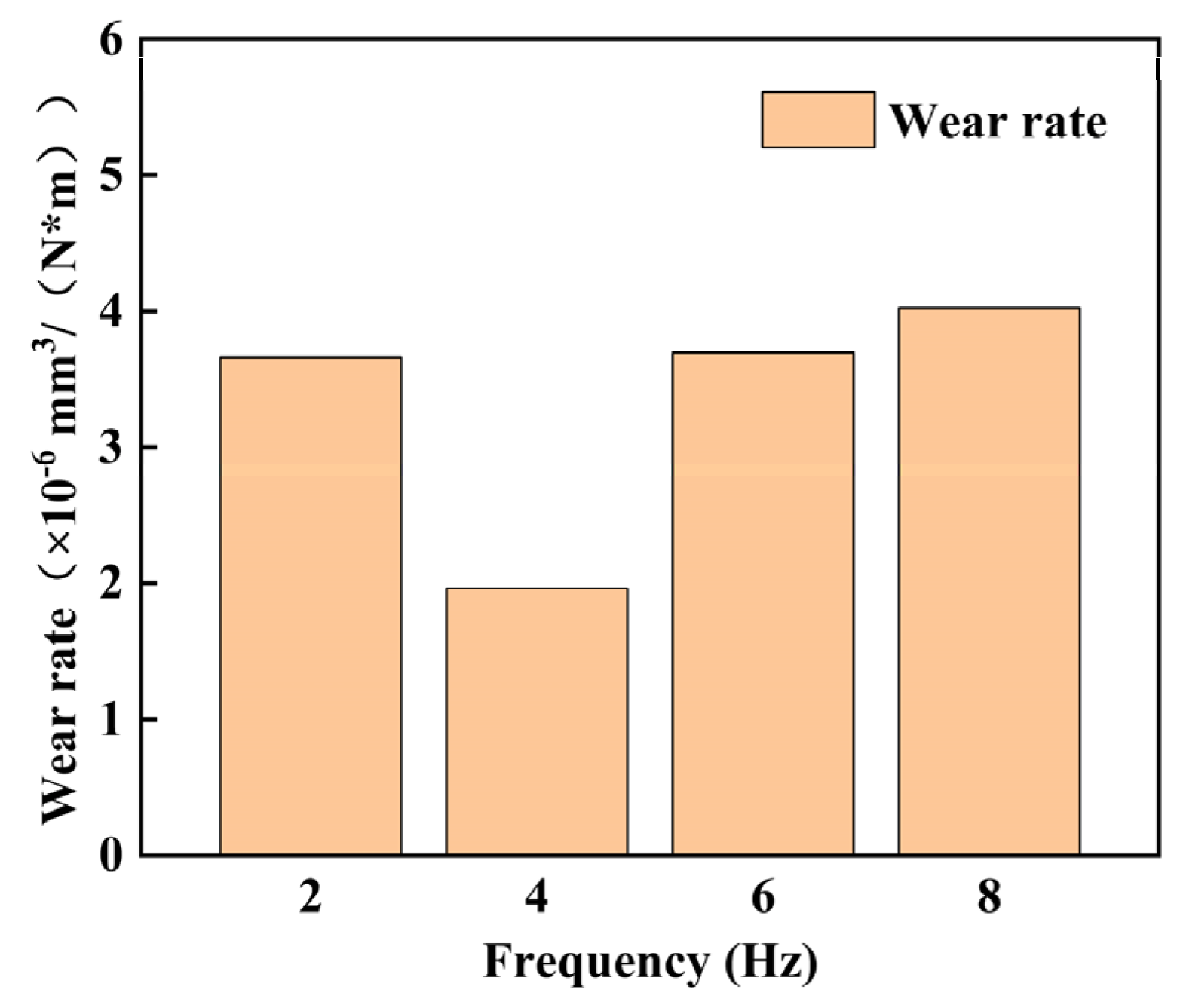
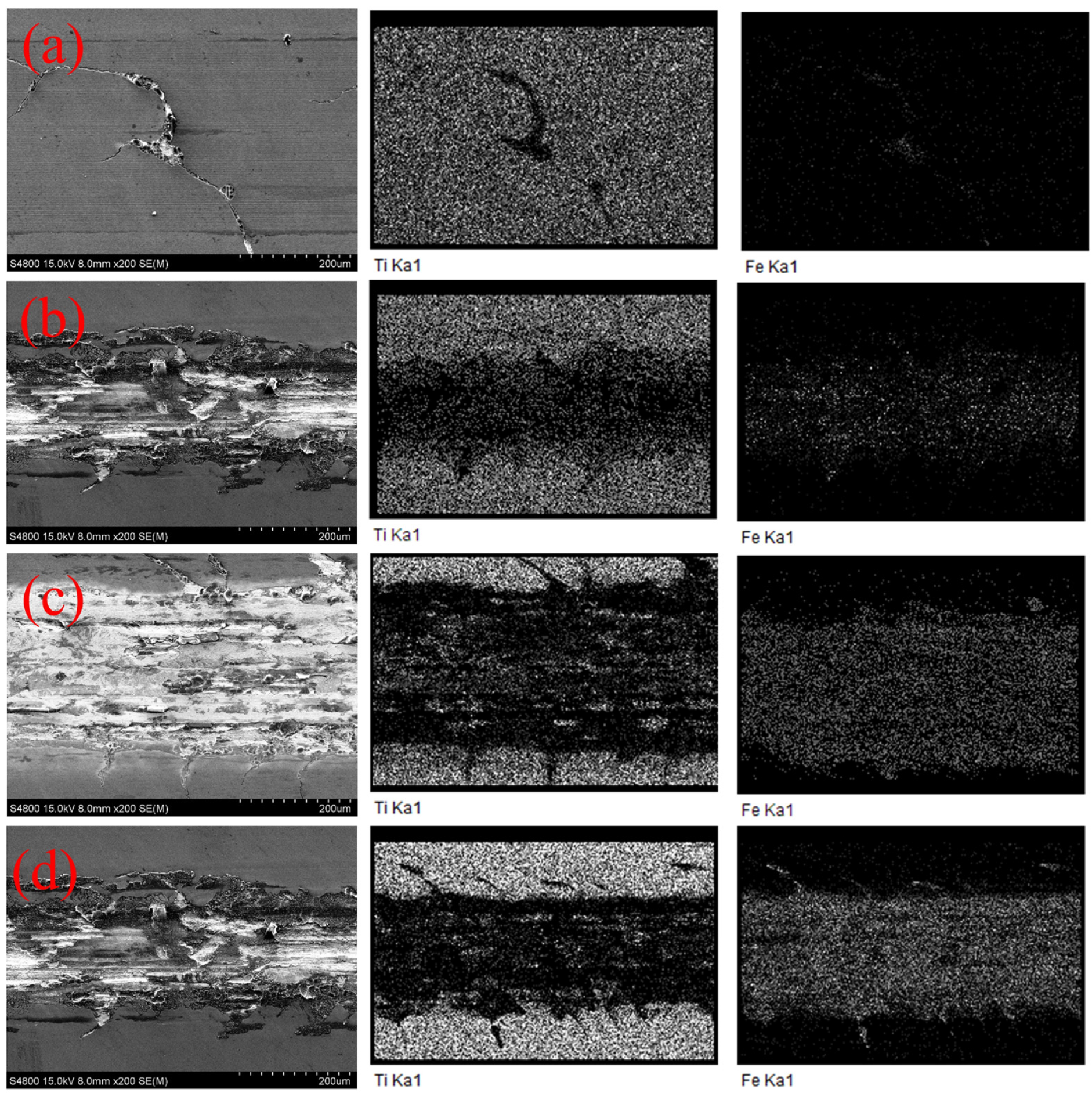
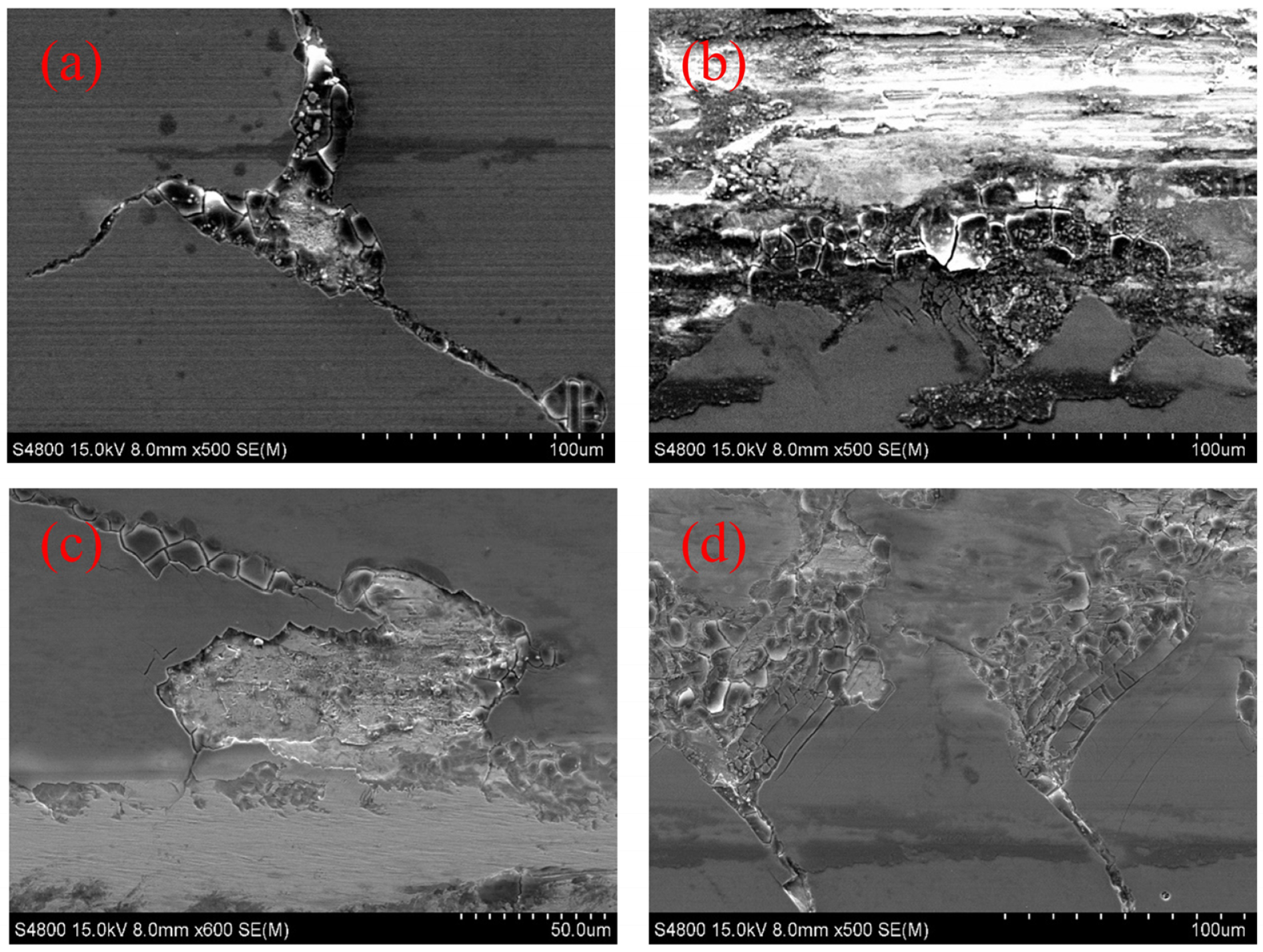
3.4.2. Tribological Properties of the TiB2 Thin Film at Different Sliding Frequencies

The tribological properties of the TiB2 thin film at different sliding frequencies (2, 4, 6, and 8 Hz) were studied. Figure 12 illustrates the friction coefficient of the TiB2 thin film at different sliding frequencies. At the beginning of the test, the friction coefficient fluctuated significantly. As mentioned earlier, at a sliding frequency of 2 Hz and a load of 5 N, the friction coefficient tends to be 0.6 after approximately 700 s. When the sliding frequency is 4 Hz, the friction coefficient fluctuates up and down at 0.7 throughout the experiment. At a sliding frequency of 6 Hz, the friction coefficient fluctuated at approximately 0.7 in the initial 400 s and subsequently stabilized at ~0.7. At a sliding frequency of 8 Hz, the friction coefficient first gradually increased and then stabilized at ~0.95 after 400 s. This may be because of the falling of the debris shed by the thin film inside the scratch during the friction experiment, which increases the frictional resistance and consequently causes the final measured friction coefficient to be high.
Table 3 and Figure 13 present the wear rates of the TiB2 thin film at different sliding frequencies under a load of 5 N. As the sliding frequency increases, the sliding length increases, and the volume of the wear trace also increases accordingly. According to the results, a wear rate of 1.96 × 10⁻⁶ mm3/(N∗m) was obtained at the sliding frequency of 4 Hz. However, under different sliding frequencies, the wear rate does not differ significantly, all within a small coefficient of 10−6 mm3/(N·m) level.
Figure 14 depicts the wear morphology of the TiB2 thin film at the sliding frequencies of 2, 4, 6, and 8 Hz. The wear is least severe at the sliding frequency of 2 Hz. At the sliding frequency of 4 Hz, the wear is more severe, and certain fragmentations are observed at the center of the wear trace. This indicates that the thin film is about to wear out. At the sliding frequencies of 6 and 8 Hz, numerous dark areas appear in the images depicting the abrasion morphology. Subsequent SEM observations have confirmed that the thin film in these areas is worn through. As the sliding frequency increases, the wear becomes more severe, accompanied by the appearance of several cracks. Furthermore, the thin-film peeling phenomenon is observed.
Figure 15 presents the SEM images and EDS surface scanning analysis results of the local wear traces at different sliding frequencies. At the sliding frequency of 2 Hz, negligible wear-through was observed inside the abrasion marks. Moreover, the Fe element was observed in the crack. However, the Fe element was not detected elsewhere in the abrasion marks. This indicates that the film has not worn through. As the sliding frequency increases, the content of the Ti element progressively decreases in the middle of the wear marks, whereas that of the Fe element correspondingly increases.
Figure 16 presents a partial enlargement of the abrasion marks on the TiB2 thin film at different sliding frequencies. Figure 16b–d depicts grooves formed by obvious plow wrinkles, which are typical of abrasive wear [31,32]. Herein, the plowing effect of abrasive wear causes damage to the trace surfaces, resulting in the wearing down of the film to the stainless steel substrate. Furthermore, pockmarks and cavities caused by the peeling off of the particles from the surface of the wear traces are observed. A large number of peeling pits are distributed on the surface, which is a characteristic of fatigue wear [33]. Accordingly, the wear of the TiB2 thin film is mainly due to fatigue and abrasion.

4. Conclusions

In this study, a hard TiB2 thin film possessing a uniform and dense structure was prepared at a low temperature using HiPIMS. And the film has preferred (001) and (101) crystal phases. The tribological properties of the deposited film at different friction loads and sliding frequencies were studied. The results indicate that the TiB2 thin film possesses satisfactory tribological properties with a low friction coefficient of 0.6 and a low wear rate of 3.66 × 10⁻⁶ mm3/(N·m) under a friction load of 5 N. Under high loads, the tribological performance of the TiB2 thin film was poor. The wear rates are small and do not differ significantly at different sliding frequencies, reaching a small coefficient of 10−6 mm3/(N·m) level. Based on the morphology and composition analyses of the wear marks, the wear of the TiB2 thin film was mainly dominated by fatigue wear and abrasive wear.

Author Contributions

Conceptualization, P.Z.; methodology, P.Z. and V.L.; validation, P.Z. and J.Y.; formal analysis, P.Z. and J.Y.; investigation, J.Y.; resources, P.Z., P.Y. and J.Y.; data curation, P.Z. and J.Y.; writing—original draft preparation, J.Y.; writing—review and editing, P.Z., P.Y., C.L. (Changhong Lin), T.Y., J.W., C.L. (Chen Li) and M.H.; visualization, J.Y.; supervision, P.Z., J.W., M.H. and V.L.; project administration, P.Z.; funding acquisition, V.L. All authors have read and agreed to the published version of the manuscript.

Funding

This work was financially supported by the Zhejiang Provincial Natural Science Foundation of China (No. LQ22E010007 and No. LTZ20E020001), Wenling Key Research and Development Project (No. 2023G00007), and Taizhou Science and Technology Plan Project (No. 22gya09).

Institutional Review Board Statement

Not applicable.

Informed Consent Statement

Not applicable.

Data Availability Statement

All data are available in this paper.

Conflicts of Interest

The authors declare no conflicts of interest.

References

  1. Akhtar, S.S. A critical review on self-lubricating ceramic-composite cutting tools. Ceram. Int. 2021, 47, 20745–20767. [Google Scholar] [CrossRef]
  2. Liu, X.; Wang, Y.; Qin, L.; Guo, Z.; Lu, Z.; Zhao, X.; Dong, H.; Xiao, Q. Friction and wear properties of a novel interface of ordered microporous Ni-based coating combined with MoS2 under complex working conditions. Tribol. Int. 2023, 189, 108970. [Google Scholar] [CrossRef]
  3. Kumar, A.; Kumar, M.; Tailor, S. Self-lubricating composite coatings: A review of deposition techniques and material advancement. In Materials Today: Proceedings; Elsevier: Amsterdam, The Netherlands, 2023. [Google Scholar] [CrossRef]
  4. Yan, Z.; Liu, J.; Zhang, X.; Hao, J.; Liu, W. WS2-Ti-based solid-liquid synergetic lubricating coating with super-high wear resistance for space application. Surf. Coat. Technol. 2024, 476, 130245. [Google Scholar] [CrossRef]
  5. Zhao-yun, Z.; Ze-wen, D.; Hai-xia, J.; Bei-bei, Z.; Xiao-yu, Z.; You-zhi, W.; Peng, W. The Influence of Doped Ti Element on Structure and Tribological Properties of WS2 Film. Surf. Technol. 2022, 51, 239–247+266. [Google Scholar]
  6. Mingling, X.; Guang’an, Z.; Xing, S.; Xi, T.; Xiaoping, G.; Yuzhe, S. Anti-oxidization and Electronic Properties of Ti Doped MoS2 Films. Chin. J. Mater. Res. 2021, 35, 59–64. [Google Scholar]
  7. Deepthi, B.; Barshilia, H.C.; Rajam, K.S.; Konchady, M.S.; Kvit, A.V. Structure, morphology and chemical composition of sputter deposited nanostructured Cr–WS2 solid lubricant coatings. Surf. Coat. Technol. 2010, 205, 565–574. [Google Scholar] [CrossRef]
  8. Cui, S.; Li, W.-S.; He, L.; Feng, L.; An, G.-S.; Hu, W.; Hu, C.-X. Tribological behavior of a Ni-WS2 composite coating across wide temperature ranges. Rare Met. 2019, 38, 1078–1085. [Google Scholar] [CrossRef]
  9. Li, P.; Xu, F.; Robertson, S.; Zhou, Z.; Hou, X.; Clare, A.T.; Aboulkhair, N.T. Metallurgical reactions and tribological properties of self-lubricating Al-WS2 composites: Laser powder bed fusion Vs. spark plasma sintering. Mater. Des. 2022, 216, 110543. [Google Scholar] [CrossRef]
  10. Li, S.; Deng, J.; Yan, G.; Zhang, K.; Zhang, G. Microstructure, mechanical properties and tribological performance of TiSiN–WS2 hard-lubricant coatings. Appl. Surf. Sci. 2014, 309, 209–217. [Google Scholar] [CrossRef]
  11. Bibeye Jahaziel, R.; Krishnaraj, V.; Sudhagar, S.; Geetha Priyadarshini, B. Improving dry machining performance of surface modified cutting tools through combined effect of texture and TiN-WS2 coating. J. Manuf. Process. 2023, 85, 101–108. [Google Scholar] [CrossRef]
  12. Serra, E.C.; Soares, V.F.D.; Fernandez, D.A.R.; Hübler, R.; Juste, K.R.C.; Lima, C.L.; Tentardini, E.K. Influence of WS2 content on high temperature wear performance of magnetron sputtered TiN-WSx thin films. Ceram. Int. 2019, 45, 19918–19924. [Google Scholar] [CrossRef]
  13. Xie, Z.-W.; Wang, L.-P.; Wang, X.-F.; Huang, L.; Lu, Y.; Yan, J.-C. Mechanical performance and corrosion behavior of TiAlSiN/WS2 multilayer deposited by multi-plasma immersion ion implantation and deposition and magnetron sputtering. Trans. Nonferrous Met. Soc. China 2011, 21, s470–s475. [Google Scholar] [CrossRef]
  14. Sala, N.; Abad, M.D.; Sánchez-López, J.C.; Crugeira, F.; Ramos-Masana, A.; Colominas, C. Influence of the carbon incorporation on the mechanical properties of TiB2 thin films prepared by HiPIMS. Int. J. Refract. Met. Hard Mater. 2022, 107, 105884. [Google Scholar] [CrossRef]
  15. Wu, Z.; Ye, R.; Bakhit, B.; Petrov, I.; Hultman, L.; Greczynski, G. Reprint of: Improving oxidation and wear resistance of TiB2 films by nano-multilayering with Cr. Surf. Coat. Technol. 2022, 442, 128602. [Google Scholar] [CrossRef]
  16. Polyakov, M.N.; Morstein, M.; Maeder, X.; Nelis, T.; Lundin, D.; Wehrs, J.; Best, J.P.; Edwards, T.E.J.; Döbeli, M.; Michler, J. Microstructure-driven strengthening of TiB2 coatings deposited by pulsed magnetron sputtering. Surf. Coat. Technol. 2019, 368, 88–96. [Google Scholar] [CrossRef]
  17. Ozkan, D.; Yilmaz, M.A.; Bakdemir, S.A.; Sulukan, E. Wear and Friction Behavior of TiB2 Thin Film–Coated AISI 52100 Steels under the Lubricated Condition. Tribol. Trans. 2020, 63, 1008–1019. [Google Scholar] [CrossRef]
  18. Jinhui, D.; Wang, P.; Yin, L.; Feng, H.; Xikun, Y. Microstructure and friction properties of WS2/TiB2 solid self-lubricant coating. Heat Treat. Met. 2016, 41, 104–109. [Google Scholar]
  19. Jin-long, L.; Hong-xuan, L.; Li, J.; Xiao-hong, L.; Ding-jun, Z. Tribological Properties of TiB2 Doped WS2 Composite Films in Wide Temperature Range. Surf. Technol. 2023, 52, 235–245. [Google Scholar]
  20. Dorri, S.; Palisaitis, J.; Greczynski, G.; Petrov, I.; Birch, J.; Hultman, L.; Bakhit, B. Oxidation kinetics of overstoichiometric TiB2 thin films grown by DC magnetron sputtering. Corros. Sci. 2022, 206, 110493. [Google Scholar] [CrossRef]
  21. Hellgren, N.; Zhirkov, I.; Sortica, M.A.; Petruhins, A.; Greczynski, G.; Hultman, L.; Rosen, J. High-power impulse magnetron sputter deposition of TiBx thin films: Effects of pulse length and peak current density. Vacuum 2024, 222, 113070. [Google Scholar] [CrossRef]
  22. Feng, A.X.; Zhang, Y.K.; Xie, H.K.; Fan, Z. Characterization of Interfacial Adhesion and Bond Strength between Thin Film Coating and Substrate by Scratch Testing. J. Jiangsu Univ. (Nat. Sci. Ed.) 2003, 24, 15–19. [Google Scholar]
  23. Ge, F.; Zhu, P.; Wang, H.; Meng, F.; Li, S.; Huang, F. Friction and wear behavior of magnetron co-sputtered V–Si–N coatings. Wear 2014, 315, 17–24. [Google Scholar] [CrossRef]
  24. Nedfors, N.; Primetzhofer, D.; Zhirkov, I.; Palisaitis, J.; Persson, P.O.Å.; Greene, J.E.; Petrov, I.; Rosen, J. The influence of pressure and magnetic field on the deposition of epitaxial TiBx thin films from DC magnetron sputtering. Vacuum 2020, 177, 109355. [Google Scholar] [CrossRef]
  25. Leyland, A.; Matthews, A. On the significance of the H/E ratio in wear control: A nanocomposite coating approach to optimised tribological behaviour. Wear 2000, 246, 1–11. [Google Scholar] [CrossRef]
  26. Lenz, B.; Hasselbruch, H.; Großmann, H.; Mehner, A. Application of CNN networks for an automatic determination of critical loads in scratch tests on a-C:H:W coatings. Surf. Coat. Technol. 2020, 393, 125764. [Google Scholar] [CrossRef]
  27. Bird, A.; Yang, L.; Wu, G.; Inkson, B.J. Failure mechanisms of diamond like carbon coatings characterised by in situ SEM scratch testing. Wear 2023, 530–531, 205034. [Google Scholar] [CrossRef]
  28. Zawischa, M.; Makowski, S.; Kuczyk, M.; Weihnacht, V. Comparison of fracture properties of different amorphous carbon coatings using the scratch test and indentation failure method. Surf. Coat. Technol. 2022, 435, 128247. [Google Scholar] [CrossRef]
  29. Kabir, M.S.; Zhou, Z.; Xie, Z.; Munroe, P. Scratch adhesion evaluation of diamond like carbon coatings with alternate hard and soft multilayers. Wear 2023, 518-519, 204647. [Google Scholar] [CrossRef]
  30. Lin-xiu, G. Introduction to the wear loss of metal materials and protection measures. Dev. Guide Build. Mater. 2020, 18, 25–26. [Google Scholar]
  31. Chi, X.; Yuan, J.; Li, J.; Pan, G.; Cui, Y.; Li, X. Effect of Cu on the high-temperature wear behavior of FeAl-TiB2 coatings produced by extreme high-speed laser cladding. Appl. Surf. Sci. Adv. 2023, 17, 100439. [Google Scholar] [CrossRef]
  32. Bao, Y.; Huang, L.; An, Q.; Zhang, R.; Geng, L.; Ma, X.; Tang, G.; Zhang, H. Wear resistance of TiB/Ti composite coating fabricated by TIG cladding using Ti-TiB2 cored wire. Surf. Coat. Technol. 2023, 474, 130086. [Google Scholar] [CrossRef]
  33. Chen, L.; Zhang, X.; Zheng, W.; Wang, M.; Liu, B.; Sun, W. Investigation on corrosion behaviors and mechanical properties of TiB2/7075Al composites with various particle contents. J. Mater. Res. Technol. 2023, 23, 2911–2923. [Google Scholar] [CrossRef]
Figure 1. Flow chart of TiB2 thin-film friction test process.
Coatings 14 00492 g001
Figure 2. SEM images of the surface morphology of (a) the Ti transition layer and (b) the TiB2 thin film at ×100 k.
Coatings 14 00492 g002
Figure 3. SEM images of the cross-sectional morphology of the TiB2 thin film at (a) ×50 k and (b) ×100 k.
Coatings 14 00492 g003
Figure 4. XRD patterns of deposited TiB2 thin film.
Coatings 14 00492 g004
Figure 5. Acoustic emission folding diagram of the TiB2 thin film.
Coatings 14 00492 g005
Figure 6. Optical map of a scratch of the TiB2 thin film.
Coatings 14 00492 g006
Figure 7. Friction coefficient of the TiB2 thin film under different friction loads.
Coatings 14 00492 g007
Figure 8. Histogram of the wear rate of the TiB2 thin film under different loads.
Coatings 14 00492 g008
Figure 9. Morphological images of abrasion marks on the TiB2 thin film under the friction loads of (a) 5, (b) 10, (c) 15, and (d) 20 N.
Coatings 14 00492 g009
Figure 10. SEM images and EDS surface scanning analysis results of local wear traces under the loads of (a) 5, (b) 10, (c) 15, and (d) 20 N.
Coatings 14 00492 g010
Figure 11. Local magnification of the abrasion marks on the TiB2 thin film under the friction loads of (a) 5, (b) 10, (c) 15, and (d) 20 N.
Coatings 14 00492 g011
Figure 12. Friction coefficient of the TiB2 thin film at different sliding frequencies.
Coatings 14 00492 g012
Figure 13. Histogram of the wear rate of the TiB2 thin film at different sliding frequencies.
Coatings 14 00492 g013
Figure 14. Wear morphology of the TiB2 thin film at the sliding frequencies of (a) 2, (b) 4, (c) 6, and (d) 8 Hz.
Coatings 14 00492 g014
Figure 15. EDS patterns of TiB2-coated abrasion marks at the sliding frequencies of (a) 2, (b) 4, (c) 6, and (d) 8 Hz.
Coatings 14 00492 g015
Figure 16. SEM images of the abrasion marks of the TiB2 thin film at (a) 2 Hz, 500×; (b) 4 Hz, 500×; (c) 6 Hz, 600×; and (d) 8 Hz, 500×.
Coatings 14 00492 g016
Table 1. Hardness and approximate modulus of elasticity of the TiB2 thin film.
SampleH (GPa)E (GPa)H/EH3/E2
TiB224.17256.800.09410.2141
Table 2. Wear rate of the TiB2 thin film under different loads at a sliding frequency of 2 Hz.
Friction Load (N)Total Sliding Length (m)Wear Volume (μm3)Wear Rate (10−6 mm3/(N·m))
536658,4483.66
10364,089,65711.36
15367,263,52613.45
203611,716,42816.27
Table 3. Wear rate of the TiB2 thin film at different sliding frequencies under a load of 5 N.
Sliding Frequency (Hz)Total Sliding Length (m)Wear Volume (μm3)Wear Rate (×10−6 mm3/(N·m))
236658,4483.66
472706,4891.96
61081,994,9953.69
81442,895,7874.02
Disclaimer/Publisher’s Note: The statements, opinions and data contained in all publications are solely those of the individual author(s) and contributor(s) and not of MDPI and/or the editor(s). MDPI and/or the editor(s) disclaim responsibility for any injury to people or property resulting from any ideas, methods, instructions or products referred to in the content.

