Article

Calculation of Stress Intensity Factor for Annular Double Cracks on Inner Surface of Pipeline

College of Mechanical and Electrical Engineering, Beijing University of Chemical Technology, Beijing 100029, China
*
Author to whom correspondence should be addressed.
Coatings 2024, 14(6), 744; https://doi.org/10.3390/coatings14060744
Submission received: 28 April 2024 / Revised: 6 June 2024 / Accepted: 7 June 2024 / Published: 12 June 2024

Abstract

:
Cracks in engineered pipelines often appear in the form of multiple cracks or crack clusters with interactions between them. It is important to study the interaction between cracks if the pipeline crack cluster is to be evaluated in terms of equivalence and safety assessment. In this paper, based on FRANC3D crack analysis software, the interaction between circumferential parallel double cracks on the inner surface of pipelines was investigated, the factors affecting the interaction were examined, and the empirical equations for calculating the stress intensity factor (SIF) of double cracks was proposed. The results show that if there is no bias between the double cracks, the crack leading edge is shielded, but if there is offset between the double cracks, the crack leading edge is subjected to different interactions at different locations. The distal end of the cracks is generally strengthened, while the proximal end of the cracks is probably more shielded. The interaction effects between cracks are dependent on their relative positions rather than the pipe size or concerned crack size. According to the numerical simulation, boundaries for shielding or enhancing interactions were obtained, and the stress intensity factor calculation equations were fitted.

1. Introduction

In petrochemical, aerospace, and other industries, the application of pressure piping is very extensive, and the safe operation of piping is one of the key factors affecting the normal operation of equipment. In reality, cracks may exist on the pipeline and may even be in the form of multi-cracks or crack groups due to processing, welding, corrosion, etc. [1]. As the direct abandonment of the pipeline containing cracks is unscientific and uneconomical, it is necessary to analyze the impact of cracks on pipeline safety. Irwin [2] in 1957 proposed the stress intensity factor theory, which lays the foundation for crack research.
At present, there are a lot of studies on single cracks in pipelines [3,4,5,6,7,8,9,10,11,12,13,14,15], but pipeline cracks often appear in the form of multiple cracks or crack groups. For multiple cracks, the study of crack interactions is of great significance. Many scholars have conducted more mature studies on double cracks on flat plates or other structures. Tanwar et al. [16] investigated the problem of antiplane stress at the interface of a composite material and obtained the variation in the stress intensity factor at the crack tip for three cracks with different crack lengths and different material combinations. Anis et al. [17] studied the problem of double cracking in flat plates, examined the factors affecting the interaction between double cracks, and gave a formula for calculating the double crack stress intensity factor. Shen et al. [18] used the complex function method and the integral method to calculate the stress intensity factor of parallel multi-cracks, analyzed the interaction mechanism between multi-cracks, and obtained the relative positions of cracks subject to enhancement or shielding. Wang et al. [19] proposed a new method to study multi-crack interactions based on the extended finite element method for calculating multi-crack stress intensity factors and predicting the direction of crack extension. Hoang et al. [20] examined the effect of crack interactions on SIFs based on experimental observations and finite element analysis and gave a formula for calculating the multi-crack stress intensity factor. Parsania et al. [21] utilized ABAQUS finite element analysis software for double cracks in infinitely large flat plates to investigate the effect of the location of the auxiliary cracks on inter-crack interactions. Han [22] studied the interactions between flat plate cracks, obtained the relative position distribution of parallel biased double cracks subjected to shielding action or enhancement, and defined and fitted the stress intensity factor correction coefficients. Zhang et al. [23] studied the interaction between non-parallel double cracks and obtained the change rule of the stress intensity factor with an inclination angle. Using the boundary element method, for the flat plate containing multi-cracks under tensile load, Huang et al. [24] investigated the boundary element method, for the flat plate containing multi-cracks under tensile load, to study the influence of multi-crack angle, length, distribution location, and spacing on the inhibition and enhancement effect. Based on the numerical simulation method of the virtual crack closure technique (VCCT), Cui et al. [25] investigated the effect of inter-crack spacing and size on the inter-crack interactions for double crack interactions in pipeline welds. Based on the 3D virtual crack closure technology (3D-VCCT), Yao et al. [26] studied the effect of auxiliary crack location and size on the stress intensity factor of the leading edge of the main crack. Hamzah et al. [27] investigated the multi-crack interactions in bonded dissimilar materials, and the results showed that the crack stress intensity factor depends largely on the elastic constants ratio, crack size, crack spacing and size, and the crack stress intensity factor, crack geometry, the distance between each crack, and the distance between the crack and the boundary. It is found from the above review that there are extensive examinations on the factors affecting the interactions between flat plate cracks, and as a result, formulas or models are proposed to quantitatively characterize the interactions between flat plate cracks.
Considering structure and application conditions, there are big differences between pipes and flat plates, so scholars also carried out studies on pipeline cracking problems. Xie et al. [28] proposed a fatigue crack extension method for pipelines with corrosion defect interactions and analyzed the interaction mechanism between cracks and corrosion defects. Sahnoun et al. [29] examined the effect of spacing on inter-crack interactions and showed that inter-crack interactions are very significant when the relative distance is less than 0.3, and vice versa, the interactions can be neglected. Chong et al. [30] investigated the effects of double crack spacing and relative size between cracks on the stress intensity factor of annular double cracks in pipelines through finite element analysis software for the interaction between multiple cracks in submarine pipelines. He et al. [31] studied the effect of the axial double crack angle on the stress intensity factor of pipelines, and the results showed that the increase in the angle between double cracks would make the stress intensity factor increase and the expansion rate increase. Yu et al. [32] studied the influence of the angle and distance between double cracks and the angle between cracks and the pipe axis on the fatigue life of submarine pipelines, and the results showed that the fatigue life of pipelines and cracks are negatively correlated with the angle of the pipe axis. Li et al. [33] and Wei et al. [34] investigated the effect of axial multi-cracks on the strength of pipelines, and the results showed that for pipelines containing double axial cracks, the stress superposition effect between cracks is gradually weakened with the increase in the spacing between double cracks, and the interaction between the cracks can be ignored when the spacing is greater than a certain value. Qin et al. [35] studied the influence law between two axial cracks in thick-walled cylinders and proved that there is a critical value for the interaction between cracks. Zhang et al. [36] investigated the effects of crack geometry, relative position, and internal pressure on the cracks for the co-linear cracks of pipelines and proposed a strain-based crack tip opening displacement estimation method for evaluating the interactions between co-linear double cracks. From the above review, it is found that although the factors affecting the interaction between pipeline cracks have been analyzed, the vast majority of articles have considered relatively simple models with one or two parameters. A comprehensive study on the interaction between cracks on pipelines is needed especially about the shielding or enhancing boundary and extent.
As mentioned above, cracks in pipelines tend to appear in the form of surface multi-cracks or crack clusters. It is important to study the interaction between cracks if the pipeline crack cluster is to be evaluated from a safety point of view. In this paper, two surface cracks inside a pipe were taken into consideration, and the interaction between the cracks in terms of the shielding or enhancing effect on the stress intensity factor of the cracks was studied. The boundary of crack shielding or enhancing interactions was drawn, and the formulas for calculating the stress intensity factor of the double cracks were fitted, which provides important references for the evaluation of double cracks in engineering.

2. Finite Element Modeling and Crack Analysis Software

2.1. Finite Element Model

In this paper, a pipe containing two circumferential parallel internal surface cracks is studied, as shown in Figure 1, and the pipe dimensions as well as the materials are given in Table 1. The pipe is subjected to a uniform distal stress σ = 22.7 MPa at one end, completely fixed at one end, and an internal pressure of p = 10 MPa inside the pipe.
Figure 2 shows the schematic diagrams of ring-oriented inner double surface cracks. In Figure 2a, a (mm) is the crack depth; 2l (mm) is the arc length of the crack on the inner surface, which is referred to as the span in this paper. In Figure 2b, two cracks are depicted. The relative long crack with points A, B, and E is called the primary crack, and the other one is called the secondary crack. h (mm) is the spacing, and s (mm) is the offset arc length between cracks. Points A and B are the two endpoints of the primary crack on the inner wall surface; E is the maximum depth point. Clearly, point A is the far point and point B the near point from the secondary crack.

2.2. Principles for Evaluating SIF in FRANC3D Crack Analysis Software

FRANC3D—V8.4 crack analysis software calculates the stress intensity factor of a crack based on the M-integral, which has a similar mathematical expression to the J-integral and can realize the superposition of the stress intensity factor for multiple conditions. FRANC3D performs the conservation integral calculation for two unit rings around the crack tip, and the integration domain includes an inner ring of 15-node singular-wedge units and an outer ring of 20-node hexahedral units. The stress intensity factors for the three fracture modes can be calculated identically. The steps and principles of M-integral calculation are as follows.
Calculate the energy release rate G by two ways; on the basis of the Irwin crack closure integral and Williams Extension [37], solve G1 by material properties and the stress intensity factor, as shown in Equation (1); on the basis of the J-integral [38,39], calculate G2 by stress, strain, and displacement, as shown in Equation (2), and the calculated area is shown in Figure 3.
G 1 = 1 v 2 E K Ι 2 + 1 v 2 E K Ι Ι 2 + 1 + v E K Ι Ι Ι 2
G 2 = V 0 ( σ i j u i x 1 1 2 σ i j ε i j δ 1 j ) q x j d V q ( s ) d s
δ 1 j = 1     ( j = 1 ) 0     ( j 1 )
where E and v are material properties; K is the stress intensity factor; σ i j , ε i j , u i j are stress, strain, and displacement; q is the virtual expansion; and V is the region of the J-integral calculation.
The principle of elastic superposition is that if there is a solution that satisfies the elastic governing equations and it is added to a second solution that satisfies the governing equations, then the result will also satisfy the governing equations. Using the elastic superposition principle, the finite element solution and the analytical solution are superimposed, and the results are as follows:
K Ι = K Ι ( 1 ) + K Ι ( 2 ) , K Ι Ι = K Ι Ι ( 1 ) + K Ι Ι ( 2 ) , K Ι Ι Ι = K Ι Ι Ι ( 1 ) + K Ι Ι Ι ( 2 )
σ i j = σ i j ( 1 ) + σ i j ( 2 ) , ε i j = ε i j ( 1 ) + ε i j ( 2 ) , u i j = u i j ( 1 ) + u i j ( 2 )
where (1) is the result of the finite element analysis; (2) is the analytic solution. Substituting Equation (4) into Equation (1), Equation (6) is obtained.
G = G ( 1 ) + G ( 2 ) + M ( 1,2 )
substituting Equation (4) into Equation (1) yields M equations about the stress intensity factor and material properties, as shown in Equation (7); substituting Equation (5) into Equation (2) yields M equations about stress, strain, and displacement, as shown in Equation (8).
M 1 ( 1,2 ) = 1 v 2 E K Ι ( 1 ) K Ι ( 2 ) + 1 v 2 E K Ι Ι ( 1 ) K Ι Ι ( 2 ) + 1 + v E K Ι Ι Ι ( 1 ) K Ι Ι Ι ( 2 )
M 2 ( 1,2 ) = V 0 σ i j ( 1 ) u i ( 2 ) x 1 + σ i j ( 2 ) u i ( 1 ) x 1 W ( 1,2 ) δ 1 j q x j d V q ( s ) d s
setting up K Ι ( 2 ) = 1 , K Ι Ι = K Ι Ι Ι = 0 yields the formula for K Ι , and solving K Ι Ι and K Ι Ι Ι follows the same principle.
K Ι ( 1 ) = E 1 v 2 V 0 σ i j ( 1 ) u i ( 2 ) x 1 + σ i j ( 2 ) u i ( 1 ) x 1 W ( 1,2 ) δ 1 j q x j d V q ( s ) d s

2.3. FRANC3D Crack Simulation Validation

For pipe circumferential inside surface cracks, API 579-1/ASME FFS-1 2016 Fitness-For-Service [40] gives the empirical formula to evaluate the stress intensity factor:
K Ι 0 = G 0 ( p R 0 2 R 0 2 R i 2 + F π ( R 0 2 R i 2 ) ) π a / Q
where Q and G0 are given by API 579-1/ASME FFS-1, F is Net-Section Axial Force. Ri and R0 are the inner and outer radii of the pipe. In order to verify the accuracy of crack modeling using FRANC3D, the FRANC3D calculation is compared with the empirical calculation of API 579-1/ASME FFS-1, and the results are listed in Table 2.
From Table 2, it is seen that the FRANC3D calculation results agree well with the API 579-1/ASME FFS-1 2016 Fitness-For-Service calculation results with a difference less than 5%, indicating that the stress intensity factor calculation using FRANC3D is reliable and accurate.

3. The Simulation of the Interaction between Two Parallel Cracks

In this section, the variation in the stress intensity factors of two parallel cracks with different sizes and different relative positions on the pipe under internal pressure is investigated. The variables include the distance and offset between the double cracks and the depth and span of the sub-cracks. Specifically, the SIFs at three points, A, B, and C, at the leading edge of the crack is used to study the interaction between the cracks. In this paper K Ι / K Ι 0 are used to express the magnitude of inter-crack interactions, where K Ι is the finite element calculation value of the stress intensity factor at the point of the leading edge of the primary crack under the influence of the secondary crack, and K Ι 0 is the stress intensity factor at the point of the leading edge of the primary crack in the absence of the secondary crack. If K Ι / K Ι 0 is greater than 1, the crack interaction is reinforcing and vice versa for shielding. In the following Section 3.1 and Section 3.2, the pipe size is kept constant as D = 50   m m , t = 5   m m ; the primary crack is used as the reference crack with the size kept constant as 2 l 1 = 8   m m , a = 2   m m , while the location and size of the secondary crack are changed for analysis.

3.1. The Effects of the Spacing and Offset between Cracks

In this subsection, the primary and secondary cracks are of the same size, and the position of the primary crack is fixed, while the location of the secondary crack is changing. The numerical simulation results are shown in Figure 4, where the red rectangular areas are the crack leading edge point corresponding to the figure.
Figure 4 gives the K Ι / K Ι 0 variation with s at points A, B, and E of the crack leading edge at different intervals. It is seen that when the spacing h increases, the shielding effect gradually decreases, and the interaction finally disappears if spacing h is large enough. The change in K Ι / K Ι 0 with the offset s is relatively complex. When the main crack overlaps the secondary crack in axial projection, the interaction is shielding on the point of the leading edge and vice versa. On the contrary, if the two cracks are not overlapped, or in other words, the two cracks are offset, their interactions tend to be enhancement. Of course, if the offset s is large compared to crack size, their interactions will also disappear. Taking the proximal point B at h = 2 mm as an example, when the offset s changes from 0 to 8 mm, the proximal point B is under the shielding effect, and the magnitude of the shielding effect is closely related to the depth of the secondary cracks at the axial overlapping on the proximal point B. The proximal point B is subjected to the enhancement effect when the offset exceeds 8 mm where the secondary crack does not overlap with the axial projection of the proximal point B. When offset s exceeds 12, the enhancement effect almost disappears, meaning the two cracks do not interact with each other.

3.2. The Effects of the Secondary Crack Size

In this subsection, the locations for the two cracks and the primary crack size are fixed, but the size of the secondary crack varies to see its influence on the primary crack. Two dimensionless numbers Ra and Rl are defined to indicate the relative dimensions of the cracks, R a = a 2 / a 1 , R l = l 2 / l 1 , where a 2 is the secondary crack depth, a 1 is the primary crack depth, l 2 is the secondary crack span, and l 1 is the primary crack span. The numerical simulation results are shown in Figure 5.
It is seen that the changing of the secondary crack size does not change the variation trend of K Ι / K Ι 0 with s. The enhancement or shielding behaviors on the primary crack stay the same, but the magnitude of the enhancement or shielding effect varies with the crack size.

3.3. Effect of Pipe and Primary Crack Size

In the above analysis, the pipe size is fixed as D = 50 mm and t = 5 mm, the pipe load is fixed as σ = 22.7 MPa and p = 10 MPa, and the primary crack size is fixed as 2l1 = 8 mm and a = 2 mm. In this subsection, the effects of the pipe size, the pipe load, and the primary crack size on K Ι / K Ι 0 are studied.
Figure 6 shows the variation in K Ι / K Ι 0 at point A with offset s for different D and t. It is seen that the effect of changing D and t on K Ι / K Ι 0 is neglectable. In fact, the pipe size may affect K Ι and K Ι 0 but has less effect on the interaction between cracks, so the effect caused by the pipe size will not be considered in the following study of this paper.
Figure 7 shows the variation in K Ι with offset s at point A for different internal pressure p and corresponding distal stress σ. It is seen that as expected, the pipe load determines K Ι , but for K Ι / K Ι 0 , which reflects the crack interactions, the pipe load has no effects, as shown in Figure 8.
Figure 9 shows the effect of the primary crack size on the interaction between cracks where a1 and 2l1 of the primary crack are changed, while Ra, Rl, and the pipe size are kept constant. Two dimensionless numbers H l = h / 2 l 1 , S l = s / 2 l 1 are defined in order to keep the spacing h and offset s varying with the crack size,   H l is the relative spacing between cracks, and S l is the relative bias between cracks. It is seen from Figure 6 that when a ≤ 0.5t, the change in the primary crack size has little effect on the crack interactions if the position between the two cracks is proportionally changed.
In summary, the finite element simulation results based on a specific pipe and primary crack size can be applied to other pipe and primary crack sizes if the relative spacing and offset are kept the same.

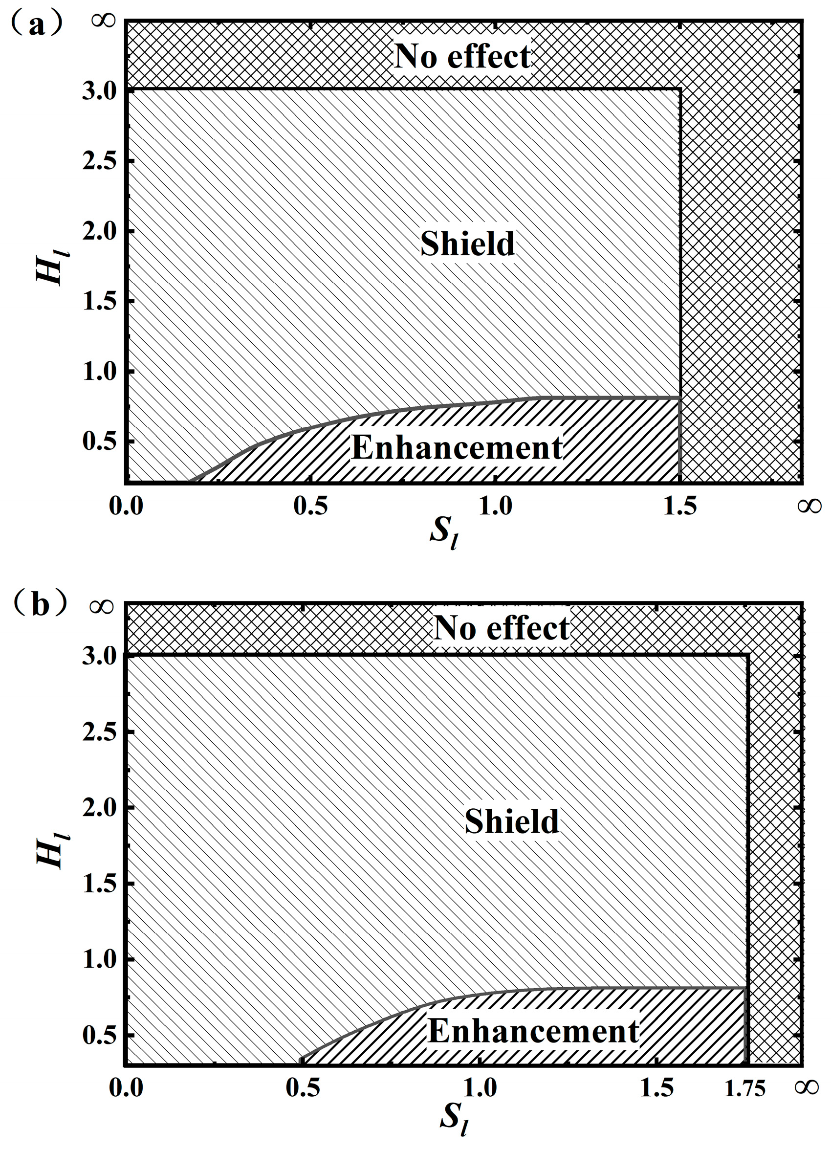
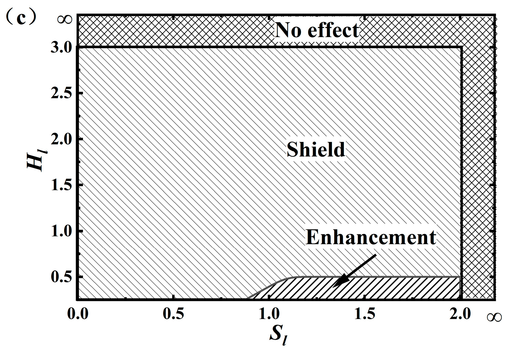
3.4. Boundaries for Shielding or Enhancing Interaction

Based on the numerical simulation results, boundaries for shielding or enhancing interaction between the two parallel cracks can be drawn, as shown in Figure 10. It is seen that when Hl or Sl is large enough, i.e., the two cracks are far from each other, no interactions occur. If Hl is relatively small and Sl is relatively large, i.e., the two cracks are closely offset, the interactions between them are more likely enhancement, especially for endpoint A.

4. Empirical Equations for Calculating Stress Intensity Factors of Crack

The above analysis reveals that the interaction between the two cracks is controlled by their relative locations and crack size. In this section, based on enough numerical simulation results, the equations for calculating the stress intensity factor of the primary crack were fitted as a function of relative spacing H l = h / 2 l 1 , offset S l = s / 2 l 1 . , and relative crack size R a = a 2 / a 1 , R l = l 2 / l 1 , and the results are listed in Table 3, Table 4 and Table 5.
The above equations are applicable to any length and diameter pipeline, but the crack depth should not exceed fifty percent of the wall thickness with the ratio of the crack depth to the span being 1:4. It turns out that when S l is greater than 2 or H l is greater than 3, there is little relative interaction between the double cracks, so K Ι / K Ι 0 is approximately equal to 1.
The above formulas quantitatively characterize the interaction between cracks. They are useful in engineering when equalizing the multi-cracks into a single crack or performing crack fatigue propagation calculation for the safety assessment of the pipelines containing cracks.
In order to validate the accuracy and applicability of the empirical equations obtained above for calculating K Ι / K Ι 0 , both equation calculation and the finite element simulation for some other double cracks within the range corresponding to the equation are performed and compared. The results are listed in Table 6. It is seen that the results of the empirical equation calculation and the finite element simulation agree well with each other with a maximum relative difference less than 4%, meaning that the equations are accurate enough in engineering application.

5. Conclusions

In this paper, the interaction between annular parallel double cracks on the inner surface of a pressure pipeline was investigated based on the FRANC3D crack simulation. Conclusions are drawn as follows.
(1) The interaction between the two cracks is mainly controlled by the locations between them. The interaction could be shielding or reinforcing.
(2) If there is no offset between the double cracks, the crack leading edge is shielded, and the smaller the spacing is, the stronger the shielding effect is. If offset occurs and the spacing is not so large between the double cracks, the distal end of the cracks is generally subjected to the reinforcing interaction, while the proximal end of the cracks is generally subjected to the shielding effect.
(3) The relative sizes of the cracks do not change the boundaries of enhancement or shielding but affect the magnitude of the enhancement or shielding. The effect of pipe size and load on crack interaction can be neglected. When a ≤ 0.5t, the change in the primary crack size has little effect on the crack interactions if the position between the two cracks is proportionally changed.
(4) For the circumferential parallel double cracks on the inner surface of a pipeline under internal pressure, boundaries for shielding or enhancing interactions and empirical equations for calculating the stress intensity factor of the primary crack were obtained based on sufficient numerical simulation results.

Author Contributions

Conceptualization, C.Q. and H.L.; Data curation, J.C.; Formal analysis, J.C. and C.Q.; Investigation, J.C.; Methodology, Z.W. and H.L.; Project administration, C.Q. and H.L.; Software, J.C.; Supervision, C.Q., H.L. and Z.W.; Validation, J.C. and C.Q.; Writing—original draft, J.C.; Writing—review and editing, C.Q. and H.L. All authors have read and agreed to the published version of the manuscript.

Funding

National Key Research and Development Program of China (Grant No. 2023YFC3010500) and the Fundamental Research Funds for the Central Universities (ZY2409).

Institutional Review Board Statement

Not applicable.

Informed Consent Statement

Not applicable.

Data Availability Statement

Data are contained within the article.

Conflicts of Interest

The authors declare no conflicts of interest.

References

  1. Shao, J.; Zhang, Q. Analysis of the causes of cracks in pressure pipelines and preventive measures. Pet. Chem. Equip. 2011, 14, 10–12. [Google Scholar]
  2. Irwin, G.R. Analysis of stresses and strains near end of a crack traversing a plate. J. Appl. Mech. 1957, 24, 361–364. [Google Scholar] [CrossRef]
  3. Mechab, B.; Malika, M.; Mokadem, S.; Boualem, S. Probabilistic elastic-plastic fracture mechanics analysis of propagation of cracks in pipes under internal pressure. Fract. Struct. Integr. 2020, 14, 202–210. [Google Scholar] [CrossRef]
  4. Tan, X.; Wang, G.; Tu, S.; Xuan, F. Comparisons of creep constraint and fracture parameter C* of different types of surface cracks in pressurized pipes. Int. J. Press. Vessel. Pip. 2019, 172, 360–372. [Google Scholar] [CrossRef]
  5. Salem, M.; Mechab, B.; Berrahou, M.; Bouiadjra, B.B.; Serier, B. Failure Analyses of Propagation of Cracks in Repaired Pipe under Internal Pressure. J. Fail. Anal. Prev. 2019, 19, 212–218. [Google Scholar] [CrossRef]
  6. Luis, E.; Antonio, J.B.; Sourojeet, C.; Daniela, G. Comparison of the Stress Intensity Factor for a Longest Crack in an elliptical Base Gas Pipe, using FEM vs. DCT method. Forces Mech. 2023, 13, 100233. [Google Scholar]
  7. Seenuan, P.; Noraphaiphipaksa, N.; Kanchanomai, C. Stress Intensity Factors for Pressurized Pipes with an Internal Crack: The Prediction Model Based on an Artificial Neural Network. Appl. Sci. 2023, 13, 11446. [Google Scholar] [CrossRef]
  8. Yao, X.M.; Zhang, Y.C.; Pei, Q.; Jin, L.Z.; Ma, T.H.; He, X.H.; Zhou, C.Y. Empirical Solution of Stress Intensity Factors for the Inclined Inner Surface Crack of Pipe under External Pressure and Axial Compression. Materials 2022, 16, 364. [Google Scholar] [CrossRef] [PubMed]
  9. Kumar, S.S.; Balaji, N.V. Mode-I, Mode-II, and Mode-III Stress Intensity Factor Estimation of Regular- and Irregular-Shaped Surface Cracks in Circular Pipes. J. Fail. Anal. Prev. 2020, 20, 1–15. [Google Scholar]
  10. Fu, G.; Yang, W.; Li, C. Stress intensity factors for mixed mode fracture induced by inclined cracks in pipes under axial tension and bending. Theor. Appl. Fract. Mech. 2017, 89, 100–109. [Google Scholar] [CrossRef]
  11. Qiu, K.; Du, P.; Wei, X.; Qu, Y.; Chen, N. Fracture phase-field method-based circumferential surface crack propagationinvestigation of pipeline. Chin. J. Ship Res. 2024, 19, 1–8. (In Chinese) [Google Scholar] [CrossRef]
  12. Zhou, Z.J.; Wen, D.; Len, X.F. Study on the stress intensity factor of pipeline outer surface cracks. Mod. Mach. 2024, 36–41. [Google Scholar] [CrossRef]
  13. Cui, Y.Y.; Li, H.F.; Qian, C.F.; Wu, Z. Calculation of stress intensity factor for pipe penetration diagonal cracks. Press. Vessel 2023, 40, 30–36+66. [Google Scholar]
  14. Chen, F.; Ding, N.; Wang, X.Y.; Zhang, F.; Liu, G. Numerical simulation of pipeline surface crack circumferential extension based on XFEM. Mater. Prot. 2022, 55, 47–54+78. [Google Scholar]
  15. Li, Z.; Jiang, X.; Hopman, H. Surface Crack Growth in Offshore Metallic Pipes under Cyclic Loads: A Literature Review. J. Mar. Sci. Eng. 2020, 8, 339. [Google Scholar] [CrossRef]
  16. Tanwar, A.; Das, S.; Craciun, E. Interaction among interfacial offset cracks in composite materials under the anti-plane shear loading. ZAMM-J. Appl. Math. Mech. 2023, 103, 202300081. [Google Scholar] [CrossRef]
  17. Anis, F.S.; Koyama, M.; Hamada, S.; Noguchi, H. Simplified stress field determination for an inclined crack and interaction between two cracks under tension. Theor. Appl. Fract. Mech. 2020, 107, 102561. [Google Scholar] [CrossRef]
  18. Shen, Q.Q.; Rao, Q.H.; Li, Z.; Yi, W.; Sun, D.L. Interacting mechanism and initiation prediction of multiple cracks. Trans. Nonferrous Met. Soc. China 2021, 31, 779–791. [Google Scholar] [CrossRef]
  19. Wang, Y.X.; Javadi, A.; Corrado, F. Analysis of Interaction of Multiple Cracks Based on Tip Stress Field Using Extended Finite Element Method. J. Appl. Math. 2022, 2022, 1010174. [Google Scholar] [CrossRef]
  20. Long, H.; Tuan, T.N. Facilitation effect of multiple crack interaction on fatigue life reduction and a quantitative evaluation of interactions factor of two parallel Non-coplanar cracks. Theor. Appl. Fract. Mech. 2023, 125, 103941. [Google Scholar]
  21. Parsania, A.; Kakavand, E.; Hosseini, A.S.; Parsania, A. Estimation of multiple cracks interaction and its effect on stress intensity factors under mixed load by artificial neural networks. Theor. Appl. Fract. Mech. 2024, 131, 104340. [Google Scholar] [CrossRef]
  22. Han, Z.C. Research on Inter-Crack Interactions and Crack Population Equivalence Method. Ph.D. Dissertation, Beijing University of Chemical Technology, Beijing, China, 2021. [Google Scholar]
  23. Zhang, R.; Han, Y. Study on the interference effect of crack strength factor on inner surface of pipeline based on ANSYS Workbench. Electromech. Eng. Technol. 2023, 52, 177–180+189. [Google Scholar]
  24. Huang, Y.F.; Qiu, J.H.; Guo, Z.Q. Boundary element analysis of fracture behavior under multi-crack interaction. Sci. Technol. Eng. 2018, 18, 6–12. [Google Scholar]
  25. Cui, W.; Xiao, Z.M.; Zhang, Q.; Yang, J.; Feng, Z.M. Modeling the Crack Interference in X80 Oil and Gas Pipeline Weld. Materials 2023, 16, 3330. [Google Scholar] [CrossRef] [PubMed]
  26. Yao, A.L.; He, W.; Xu, T. 3D-VCCT based fracture analysis method for gas pipelines with multiple cracks. Nat. Gas Ind. B 2019, 6, 488–496. [Google Scholar] [CrossRef]
  27. Hamzah, K.; Long, N.N.; Senu, N. Stress intensity factor for multiple cracks in bonded dissimilar materials using hypersingular integral equations. Appl. Math. Model. 2019, 73, 95–108. [Google Scholar] [CrossRef]
  28. Xie, M.J.; Wang, Y.F.; Xiong, W.N.; Zhao, J.L.; Pei, X.J. A Crack Propagation Method for Pipelines with Interacting Corrosion and Crack Defects. Sensors 2022, 22, 986. [Google Scholar] [CrossRef] [PubMed]
  29. Sahnoun, M.; Ouinas, D.; Bouiadjra, B.B.; Olay, J.V. Numerical Modelling of the Interaction Macro–Multimicrocracks in a Pipe under Tensile Stress. Adv. Mater. Res. 2015, 1105, 245–250. [Google Scholar] [CrossRef]
  30. Chong, Z.W.; Ma, T.X.; Yu, D.L.; Wu, D.R.; Tao, J.; Lv, H. Stress Intensity Factor of Double Cracks on Seabed-Spanning Pipeline Surface under the Spring Boundary. J. Pipeline Syst. Eng. Pract. 2021, 12, 04021052. [Google Scholar] [CrossRef]
  31. He, X.; Qin, X.; Xie, L. Influence of pipe axial double crack angle on tip stress intensity factor. J. Northeast. Univ. (Nat. Sci. Ed.) 2011, 32, 1623–1626. [Google Scholar]
  32. Yu, J.; Guo, S.; Wu, Z. Analysis of fatigue life of submarine pipelines containing double crack defects. China Offshore Platf. 2016, 31, 66–72. [Google Scholar]
  33. Li, W.; Tan, Y.; Wu, W. Effect of two-crack interaction on the stress intensity factor of pipelines. Oil Gas Storage Transp. 2019, 38, 1125–1129. [Google Scholar]
  34. Wei, M. Research on multi-crack interaction and effect on strength of its main steam pipeline. China Spec. Equip. Saf. 2019, 35, 70–75. [Google Scholar]
  35. Qin, Y.; Qin, X.; Chen, Z. Study on the influence law between parallel biaxial cracks on the inner surface of thick-walled cylinders. Electromech. Eng. 2022, 39, 276–280. [Google Scholar]
  36. Zhang, Y.; Fan, M.; Xiao, Z. Nonlinear elastic-plastic stress investigations on two interacting 3-D cracks in offshore pipelines subjected to different loadings. AIMS Mater. Sci. 2016, 3, 1321–1339. [Google Scholar] [CrossRef]
  37. Williams, L.M. On the Stress Distribution at the Base of a Stationary Crack. J. Appl. Mech. 1957, 24, 109–114. [Google Scholar] [CrossRef]
  38. Rice, J.R. A Path independent integral and the approximate analysis of strain concentrations by notches and cracks. J. Appl. Mech. 1968, 35, 379–386. [Google Scholar] [CrossRef]
  39. Rice, J.R.; Rosengren, G.F. Plane strain deformation near crack tip in a power-law hardening material. J. Mech. Phys. Solids 1968, 16, 1–12. [Google Scholar] [CrossRef]
  40. API 579-1/ASME FFS-1; Fitness-for-Service. American Petroleum Institute: Houston, TX, USA, 2016.
Figure 1. Schematic of pipe loads and constraints.
Coatings 14 00744 g001
Figure 2. Schematic diagrams of cracks: (a) crack on the annular inner surface of the pipe; (b) double cracks.
Coatings 14 00744 g002
Figure 3. Schematic diagrams of the leading edge of the crack.
Coatings 14 00744 g003
Figure 4. Variation in K Ι / K Ι 0 with s for different h(mm): (a) point A; (b) point E; and (c) point B.
Coatings 14 00744 g004aCoatings 14 00744 g004b
Figure 5. Variation in K Ι / K Ι 0 with s for different Ra and Rl: (a) point A; (b) point E; and (c) point B.
Coatings 14 00744 g005
Figure 6. Variation in K 1 / K 1 0 at point A with s for different D and t.
Coatings 14 00744 g006
Figure 7. Variation in K 1 at point A with s for different p and σ.
Coatings 14 00744 g007
Figure 8. Variation in K 1 / K 1 0 at point A with s for different p and σ.
Coatings 14 00744 g008
Figure 9. Variation in K 1 / K 1 0 with S l for different a1 and 2l1 at point A.
Coatings 14 00744 g009
Figure 10. Boundaries for shielding or enhancing interaction between the two cracks: (a) point A; (b) point E; and (c) point B.
Coatings 14 00744 g010aCoatings 14 00744 g010b
Table 1. Pipe sizes and materials.
MaterialsYoung’s ModulusPoisson’s RatioInside
Diameter
Wall
Thickness
Length
S30408195 GPa0.3D (mm)t (mm)5(D + 2t) (mm)
Table 2. A comparison of the results by FRANC3D with those of API 579-1/ASME FFS-1.
a/mmc/mmD/mmt/mmFRANC3D
K 1 0 (Point E)
ASME FFS-1
K 1 0 (Point E)
Relative Difference
1150526.7825.783.9%
1250535.9336.391.3%
2250538.4639.532.7%
2450553.0953.500.8%
3350547.2849.284.1%
3650568.5469.110.8%
Table 3. Empirical equations for calculating SIFs at point A.
StepsFormulas
δ 1 0.25 < H l 1 S l 0.87 H l + 0.33 , δ 1 = A 1 B 1 C 1 18.35 S l
A 1 = 1.05 0.032 H l + 0.018 H l 2
B 1 = 0.31 0.43 H l + 0.23 H l 2
C 1 = 0.37 + 1.03 H l 0.46 H l 2
S l > 0.87 H l + 0.33 , δ 1 = 1 + A 1 1 1 + 10 C 1 ( B 1 18.35 S l )
A 1 = 1.07 0.13 H l 0.062 H l 2
B 1 = 18.61 + 2.17 H l + 4.35 H l 2
C 1 = 0.1 0.02 H l 0.21 H l 2
1 < H l 3 δ 1 = 18.35 ( 1 A 1 ) S l 30 + A 1 A 1 = 0.85 + 0.1 H l 0.018 H l 2
δ 2 δ 2 = A 2 + B 2 R l + C 2 R l 2
A 2 = 0.99 0.011 R a
B 2 = 0.037 + 0.1 R a
C 2 = 0.073 0.23 R a
K Ι K Ι 0 K Ι K Ι 0 = 1 ( 1 δ 2 ) ( 1 δ 1 ) / 0.1117
Table 4. Empirical equations for calculating SIFs at point E.
StepsFormulas
δ 1 0.25 < H l 1 S l 0.87 H l + 0.545 , δ 1 = A 0 + A 1 A 0 1 + 10 C 1 ( B 1 18.35 S l )
A 0 = 0.69 + 0.36 H l 0.13 H l 2
A 1 = 1.12 0.262 H l + 0.14 H l 2
B 1 = 3.37 + 7.66 H l 1.82 H l 2
C 1 = 0.33 0.37 H l + 0.148 H l 2
S l > 0.87 H l + 0.545 , δ 1 = 1 + A 1 1 1 + 10 C 1 ( B 1 18.35 S l )
A 1 = 1.18 0.39 H l + 0.218 H l 2
B 1 = 14.49 + 9.61 H l + 2.718 H l 2
C 1 = 0.15 + 0.36 H l 0.522 H l 2
1 < H l 3 δ 1 = 18.35 ( 1 A 1 ) S l 30 + A 1 , A 1 = 1 0.32 0.83 8 H l
δ 2 δ 2 = A 2 + B 2 R l
A 2 = 0.98 0.015 R a + 0.048 R a 2
B 2 = 0.038 0.066 R a 0.14 R a 2
K Ι K Ι 0 K Ι K Ι 0 = 1 ( 1 δ 2 ) ( 1 δ 1 ) / 0.1530
Table 5. Empirical equations for calculating SIFs at point B.
SchemeFormulas
δ 1 0.25 < H l 1.25 0 S l 0.81 ,
δ 1 = A 1 + 4.59 ( B 1 A 1 ) S l + 5.26 ( A 1 B 1 ) S l 2
A 1 = 0.756 + 0.31 H l 0.125 H l 2
B 1 = 0.95 1.37 0.632 8 H l
0.81 < S l 0.87 H l + 0.87 ,
δ 1 = A 1 + B 1 S l + C 1 S l 2
A 1 = 0.78 24.01 0.44 8 H l
B 1 = 0.255 48.21 0.425 8 H l
C 1 = 0.077 + 24.14 0.41 8 H l
S l > 0.87 H l + 0.87 , δ 1 = A 1 + A 0 A 1 1 + e ( 18.35 S l B 1 ) / C 1
A 0 = 1.20 0.55 H l + 0.383 H l 2
A 1 = 1.01 0.023 H l + 0.0134 H l 2
B 1 = 25.65 3.03 H l + 12.57 H l 2
C 1 = 1.34 + 3.6 H l 5.894 H l 2
1.25 < H l 3 δ 1 = 18.35 ( 1 A 1 ) S l 34 + A 1 , A 1 = 1.005 0.213 0.868 8 H l
δ 2 δ 2 = A 2 + B 2 R a + C 2 R a 2
A 2 = 0.85 + 0.31 R l 0.31 R l 2
B 2 = 0.2 0.37 R l + 0.19 R l 2
C 2 = 0.11 + 0.2 R l 0.23 R l 2
K Ι K Ι 0 K Ι K Ι 0 = 1 ( 1 δ 2 ) ( 1 δ 1 ) / 0.1139
Table 6. Accuracy validation for the empirical equations.
D t 2 l 1 a R l R a H l Average DifferenceMaximum Difference
50582115.51.01%2.22%
505821190.85%1.48%
505820.850.9531.13%1.51%
505820.50.760.92%1.82%
7015821141.83%3.32%
80201230.80.821.85%3.62%
505410.750.7531.94%2.74%
5005080201141.41%2.27%
Disclaimer/Publisher’s Note: The statements, opinions and data contained in all publications are solely those of the individual author(s) and contributor(s) and not of MDPI and/or the editor(s). MDPI and/or the editor(s) disclaim responsibility for any injury to people or property resulting from any ideas, methods, instructions or products referred to in the content.

