Review

PbS Colloidal Quantum Dots: Ligand Exchange in Solution

Key Laboratory of Automobile Materials MOE, School of Materials Science & Engineering, Jilin University, Changchun 130012, China
*
Author to whom correspondence should be addressed.
Coatings 2024, 14(6), 761; https://doi.org/10.3390/coatings14060761
Submission received: 22 May 2024 / Revised: 9 June 2024 / Accepted: 12 June 2024 / Published: 16 June 2024
(This article belongs to the Special Issue Advances in Nanostructured Thin Films and Coatings, 2nd Edition)

Abstract

:
PbS colloidal quantum dots (CQDs) have the advantages of adjustable band gap, large exciton Bohr radius, controllable size, easy synthesis, and potential multi-exciton effect, making them attractive for photodetectors and solar cells. However, the long ligand chain wrapped on PbS CQDs limits carrier transport, and defect states of as-synthesized CQDs increase non-radiative recombination, negatively affecting photovoltaic performance. Surface properties determine the characteristics of CQDs, so ligand exchange processes are crucial. Because solution phase ligand exchange reduces labor and time requirements, it is more advantageous than solid phase ligand exchange. This review discusses the solution phase ligand exchange process of PbS CQDs, emphasizing the impact of surface ligands on conformation and conductivity.

1. Introduction

Colloidal quantum dots (CQDs) are nanoscale semiconductor crystals coated with surfactant molecules and dispersed in solution, which have attracted much attention in the research and development of novel photodetectors, photovoltaic cells, light-emitting diodes, and chemical sensors [1,2,3,4,5]. Apart from solution processing, a key benefit of CQDs is their quantum confinement property [5]. It is possible to customize the optical and electrical properties of nanoparticles by adjusting their size and shape [6]. Lead sulfide (PbS) is a narrow band gap semiconductor material with a large exciton Bohr radius [7]. As a result of its considerable quantum size effect, it is one of the earliest and most rapidly developed CQD systems.
The smaller the CQD size, the larger the number of surface atoms exposed, resulting in an increase in coordination sites. Consequently, CQDs become more active and have a higher surface energy, which ultimately leads to increased oxidation, adsorption, and interaction. The organic surface ligands (oleic acid [8], oleamine [9], etc.) of CQDs can be used to control the nucleation and growth rate in synthesis and maintain quantum dot stability. Ligands also isolate oxygen and CQDs to prevent oxidation, so that CQDs can be stored in nonpolar solvents for a long time without aggregation [10,11]. However, long-chain alkyl ligands are insulating, which interferes with charge transfer in CQD films, resulting in poor device performance [12]. In order to improve CQD performance, ligand exchange engineering should be used to replace long chains with short chains or atomic ligands. This review examines the solution phase ligand exchange process and its application to PbS CQD solar cells.

2. Solution Phase Ligand Exchange

Ligand exchange is divided into solid-state ligand exchange and solution-state ligand exchange. The solid-state ligand exchange method is shown in Figure 1a. It usually involves surface treatment by immersing a film of CQDs or drip-coating it with a solution of specific ligands. As the original long-chain organic ligands on the surface of the CQDs are removed and replaced with “shorter” target ligands, the spacing between the CQDs becomes smaller, facilitating carrier transport [12]. Although the solid ligand exchange method has been widely used in the preparation of PbS quantum dot thin film photovoltaics, there are still some limitations. For example, during solid ligand exchange, partial loss of ligands can occur through protic solvent effects. In addition, in order for solid ligand exchange to produce thick films of CQDs to obtain sufficient light collection, a layer-by-layer method needs to be carried out, which requires a long time to manufacture and a large amount of materials [13,14].
To solve these problems, researchers developed solution phase ligand exchange technology. The solution phase ligand exchange technique is shown in Figure 1b. It dissolves CQDs wrapped with long-chain alkyl ligands in nonpolar solvents and dissolves hydrophilic organic molecules or inorganic molecules with short-chain ligands in polar solvents [14]. Then the two solutions are mixed, and the long-chain alkyl ligands are replaced by hydrophilic short-chain ligands or atoms, so that the CQDs are transferred from the non-polar solvent to the polar solvent, thus completing the quantum dot ligand replacement process directly in the solution.

3. Characterization of CQDs and Devices

We need characterization to detect whether ligand exchange is taking place. The synthesized CQDs need XRD (X-ray diffraction) [16] for phase analysis to complete the qualitative identification and quantitative calculation of the phase composition and structure of the sample. XPS (X-ray photoelectron spectroscopy) [16] testing is required to determine the surface element composition and chemical state molecular structure of the sample, so that we can know whether the surface ligand is exchanged into a short-chain ligand. The UPS (ultraviolet photoelectron spectroscopy) [17] test principle is the same as XPS, but UPS emits ultraviolet light to irradiate the sample and detect the sample valence band and conduction band position. The UV–visible absorption spectrum uses a beam of light with a wavelength range of 300~1200 nm to irradiate the sample. The incident photon is absorbed by the material and leads to the excited electron transition of the material. Each material has its specific peak. The principle of the PL spectrum (photoluminescence spectrum) [16] is as follows. Under the excitation of incident light, the electrons in the material transition from valence band to conduction band and leave a hole. After a period of relaxation, the photogenerated electrons and the hole reach an equilibrium state, and then the photoluminescence phenomenon is generated by recombination. The absorption spectrum and PL spectrum peak are used to explore the dispersion of CQDs, lattice defects, and other properties. IR [18] spectroscopy is mainly used for the structural analysis of material groups and qualitative and quantitative analysis of materials. By measuring the signal changes of long carbon chain chemical bonds before and after passivation of PbS quantum dots, we can determine whether ligand exchange has occurred. NMR is used to study the absorption of radio-frequency radiation by atomic nuclei. It is one of the most powerful tools for qualitative analysis of the composition and structure of various organic and inorganic substances, and sometimes it can also be used for quantitative analysis. SEM (scanning electron microscope) [16] is mainly used to analyze the morphology of device structure, TEM (transmission electron microscope) [16] is mainly used to analyze the morphology of CQDs, and AFM (atomic force microscope) [16] is mainly used to analyze the size distribution of CQDs.
There are several methods to study carrier dynamics. TA (transient absorption) [19] is a detailed dynamic process of material molecules’ transition from excited states to other low-energy states or ground states based on pump detection technology. It is mainly used to explore the dynamic process of carriers in CQDs. PLQY (photoluminescence quantum yield) can characterize the luminescence efficiency of a sample, that is, measure the efficiency of the sample to effectively utilize the absorbed light. TRPL (time-resolved fluorescence) [16] spectroscopy is mainly used to measure carrier lifetime through attenuation curves. The study of TPV (transient photovoltage) [20] and TPC (transient photocurrent) [20] is the key means to reveal the microscopic working mechanism of photovoltaic devices. By analyzing the TPV and TPC detection data, we can obtain the dynamic process information of carrier transport, accumulation, and recombination in photovoltaic devices. EQE (external quantum efficiency) [21] refers to the ratio of the number of photons emitted by the device to the number of injected carriers, reflecting the overall luminous efficiency of the device. The density of defect states is mainly seen in solar cells. We use the FET (field effect transistor) [22] to study the mobility and trap state density of the exchanged CQD films. GISAXS (grazing incidence Small Angle X-ray Scattering) [19] mainly measures the nanoparticle (structure) information on and inside the surface film.

4. Principles of Ligand Exchange in Solution

The main purpose of solution phase ligand exchange is ligand removal and passivation. The synthesized PbS CQDs have a large number of oleic acid (OA) ligands. However, the long-chain OA ligands are insulators, which will affect carrier transport [12]. Generally, in solar cell applications, the long-chain ligand is replaced by the short-chain ligand to reduce carrier transmission obstruction, reduce trap states, increase mobility, and increase tunneling probability [12]. The ligands on the surface of CQDs have a significant effect on the physical and chemical properties of CQDs. The CQD surface is modified by halide ions after the phase transfer process. At the same time, the stability of CQD ink is also affected by the chemical properties of the CQD surface, so the ligand exchange process is very important. The principle of ligand exchange in solution phase is shown in Figure 2. PbX2 dissolved in DMF solution is added to the quantum dot solution capped by OA. After mixing and stirring, CQDs are transferred from the nonpolar phase (octane) to DMF, and the OA ligand is replaced by a halide ligand, assisted by additive ions [19]. The surface of CQDs is easily affected by the environment, so the solution phase ligand exchange needs to passivate the surface of CQDs. The short-chain ligand increases the surface coverage, reduces the attack of water and oxygen, reduces defect states, reduces nonradiative recombination, and increases carrier lifetime [11,23].

4.1. Ligand Exchange of (111) Facet

The surface of the synthesized PbS CQDs is mainly composed of a lead-rich (111) facet and a small amount of (100) facet. The smaller the size of (111) facets, the larger the proportion of (111) facets [7].
In general, the original ligand exists on the (111) facet, and the surface ligand is removed to reduce trap states and improve carrier mobility. A large number of studies have been conducted on the removal of the OA ligand. The additives and chemical reaction equations used are shown in Table 1. The purpose of additives is to accelerate the removal of the OA ligand and increase the coating of the replacement ligand. For the (111) facet, ligand removal is as important as passivation.
In 2016, Sargent et al. [19] proposed a new solution phase ligand exchange process using lead halide and ammonium acetate. The solution phase ligand exchange process is shown in Figure 3a. During the exchange process, the bulky oleic acid ligand is replaced by [PbX3] anion with the help of ammonium ion. Both [NH4]+ and [PbX]+ contribute to the colloid stabilization of nanocrystals in polar solvents. After ligand exchange, CQDs are precipitated by adding antisolvent. The mixed solvent takes away NH4Ac and excess lead halide salts, leaving [PbX3]/[PbX]+-capped CQDs solid without any organic residues.
Metal halide perovskite has a good lattice match with PbS, and perovskite becomes a new modified material on the surface of PbS CQDs, forming a core–shell structure [24]. MAPbI3 has been used as the surface ligand of PbS, but the device efficiency is low. In 2017, Xiaoliang Zhang et al. [16] used CsI and PbI2 to grow a CsPbI3 perovskite layer on the surface of PbS as the surface ligand, and achieved 10.5% power conversion efficiency. The solution phase ligand exchange process is shown in Figure 3b. Perovskite has a good match with PbS, which is coated with PbS.
Inorganic ligands are now widely used, but the use of liquid ligand exchange methods remains challenging. In 2019, Donglin Jia et al. [18] used NH4I as the ligand to passivate the surface of CQDs. The ligand exchange process is shown in Figure 3c. NH4I is dissolved in DMF solution, PbS solution is injected into DMF solution, NH4I ligand replaces OA, precipitated with reverse solvent, and is finally dissolved in propylene carbonate. Lead halide was also used as a ligand for comparison. The results show that the ammonium ion interacts with the iodide ion to form a charge layer on the surface of the CQDs, and the moderate Lewis base of propylene carbonate makes the quantum dot solution of the NH4I ligand more stable [18].
In the early-phase ligand exchange studies, lead halide was combined with organic salts (CH3NH3I, NH4I, and CH3CH2COONH4), but the organic part was not directly involved in the passivation of the terminal surface sites of CQDs [25]. The iodine atom passivates the unsaturated metal atoms on the surface of the quantum dot, while the organic part’s role is limited to the charge balance that provides colloidal stability for the quantum dot. In 2019, Debranjan Mandal et al. [25] passivated the surface of CQDs using a solution mixture of lead halide-NH4I and 3-chloro-1-Propanethiol (CPT). As shown in Figure 3f, the OA ligand is removed. In the case of mixed passivation, the optical and electrical properties of PbS CQDs are obviously improved due to the increase in dispersion and the decrease in electron trap state, and the efficiency of the hybrid passivation solar cell reaches 10.3% [25]. This passivation strategy is compatible with the solution phase ligand exchange process and allows the development of quantum dot inks for one-step deposition of thick conductive CQDs films. Advances in surface engineering have resulted in higher monodispersion and lower defect density of quantum dot solids.
CQDs such as metal chalcogenides can be tuned to absorb infrared photons and designed as solar cells, which could complement existing photovoltaic technologies based on crystalline silicon, which cannot absorb photons above 1100 nm. Previous single lead halide passivation strategies led to poor performance of infrared solar cells due to passivation or poor transport [26]. James Z. Fan et al. [27] 2019 reported a hybrid metal halide passivation strategy that combines multiple lead halides (PbI2, PbBr2, and PbCl2) to achieve surface passivation (Figure 3d). Compared with PbS film passivated by PbI2, the surface coverage and mobility of PbS solid passivated by mixed lead halide ligand increased 1.7 times and 1.6 times, respectively. These devices have higher open-circuit voltage and maintain higher short-circuit current density.
After a lot of device engineering research, the efficiency of infrared PbS devices has been increased to more than 1% [26]. The strong steric hindrance of the original ligand prevents the diffusion of lead halide, resulting in a large energy barrier for ligand exchange. Therefore, a considerable portion of the original ligand remains on the surface of CQDs, resulting in poor carrier transport [28]. Mengxia Liu et al. [28] found that surface passivation of CQDs can be promoted by using short-chain carboxylate. Short-chain carboxylic groups increase the packing density of the ligands, forcing the oleates to rearrange due to spatial effects, ultimately weakening their binding [28]. The process is shown in Figure 3e. Due to steric hindrance, the presence of short-chain carboxylate alters the optimal geometric configuration of oleate, and the use of carboxylate provides a halogenated saturated surface, showing less OA residue.
Figure 3. The process of ligand exchange when different additives are used. (a). Solution phase ligand exchange with metal halide precursors and ammonium acetate. Reprinted from reference [19]. Copyright 2016 Springer Nature Limited. (b). Schematic illustration of the fabrication process of inorganic CsPbI3-P coating on the PbS CQDs. Reprinted from reference [16]. Copyright 2017 WILEY-VCH. (c). Process of solution state ligand exchange with AI to replace the OA on QD surface. Reprinted from reference [18]. Copyright 2019 WILEY-VCH. (d). Typical lead halide exchange from an oleate-capped PbS CQDs to a halide-capped PbS CQDs. Reprinted from reference [27]. Copyright 2019 WILEY-VCH. (e). Schematic depicting formate-assisted ligand exchange on PbS(111) facets. Reprinted from reference [28]. Copyright 2019 American Chemical Society. (f). Schematic representation of oleic acid (OA)-capped, AI- and CPT + AI-treated PbS CQD surface. Reprinted from reference [25]. Copyright 2019, American Chemical Society.
Coatings 14 00761 g003

4.2. Passivation of (100) Facet

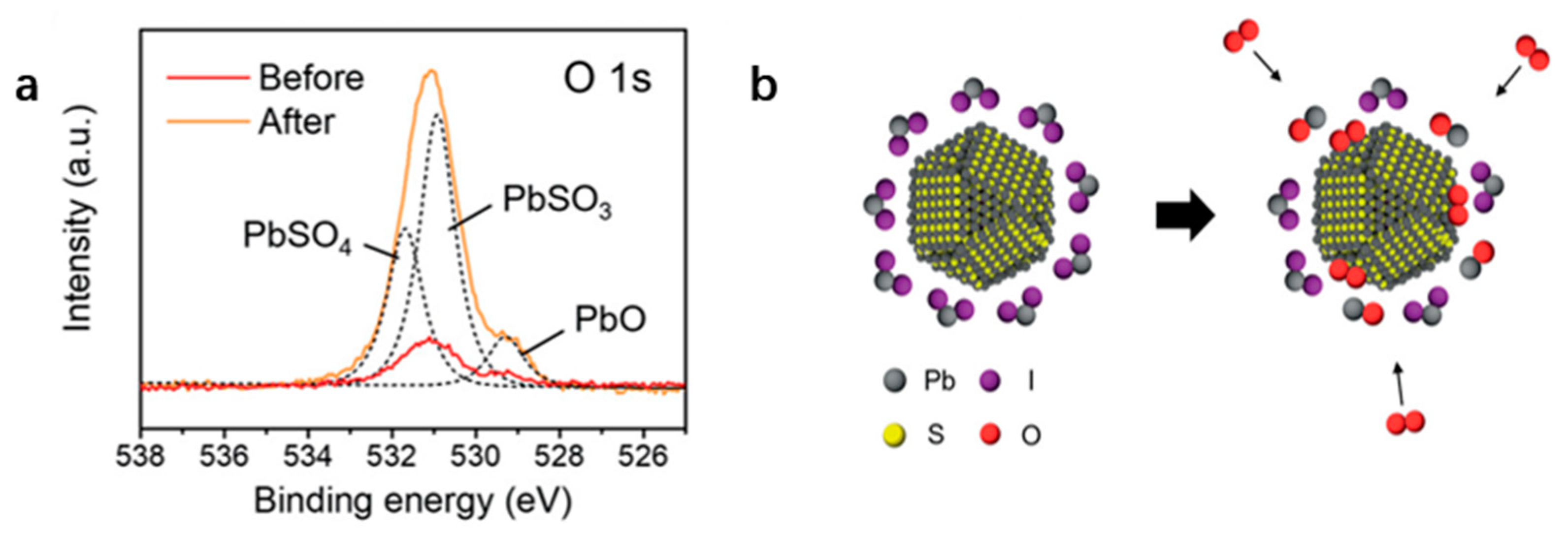
In the solution phase ligand exchange method optimized for small-diameter PbS CQDs, the ligand exchange between the native oleate ligand and the lead halide anion with the assistance of NH4+ mainly occurs on the polar (111) side of the Pb enrichment site. However, this approach is not applicable for large-diameter PbS CQDs. As the CQD size increases, the portion of nonpolar (100) facet with low surface energy increases at the expense of the cation-rich polar (111) facet [7,29]. Oleic acid is more weakly bound to the nonpolar (100) facet compared to (111) facet [30]; indeed, it detaches readily from the (100) facet in polar solvents. The (100) facet has fewer ligands and is vulnerable to oxidation, which leads to the increase in defect state density, the increase in nonradiative recombination of carriers, and the influence of carrier transport. Figure 4a shows the XPS O ls spectra [31]. Due to the fewer ligands of the (100) facet, the PbS on the surface of (100) is oxidized to form PbSO4 and PbSO3 [31]. At present, there are some studies on passivation of the (100) facet, and the additives currently used are shown in Table 2. For the (100) facet, passivation is dominant and ligand removal is complementary.
The surface of PbS (100) has less ligands due to the presence of S. Most methods of passivation of the PbS (100) facet use large cations to bind S and lead halide to Pb. In 2019, Sargent et al. [32] adopted NaAc as an additive. NH4Ac can enhance the removal of the original ligand, but cannot passivate the (100) facet. Na ions can selectively passivate the non-polar (100) facet (Figure 5c), resulting in passivation of both the (100) and (111) facet of the CQD surface [32]. The theoretical calculation results also show that the adsorption strength of Na+ on the (100) facet is stronger than that of NH4+ [32]. Since Na+ passivates the (100) facet, the aggregation of CQDs is reduced and the number of ligands on the surface of CQDs is increased, which is beneficial to the stability of CQDs and the efficiency of the device. Later, after KI was used as an additive and the OA ligand was replaced by the halide ligand, K+ ions passivated the (100) facet to reduce the oxide on the CQD surface (Figure 5a), and I, as a passivating agent, could passivate the (111) facet, increasing the halide surface coverage and surface passivation [31]. The shielding effect of KI increases the device efficiency from 11.4% to 12.6%. In 2020, Shujuan Huang et al. [17] used KI3 as an additive. Using KI3, the advantages of KI and I2 can be combined. By reacting with free I2 molecules, the low-charge Pb and suspended S sites on CQDs are eliminated. PbX2 and KI ligands construct a strong high-surface covering shell on CQD to inhibit water or oxygen attack.

4.3. Removal of Hydroxyl (-OH)

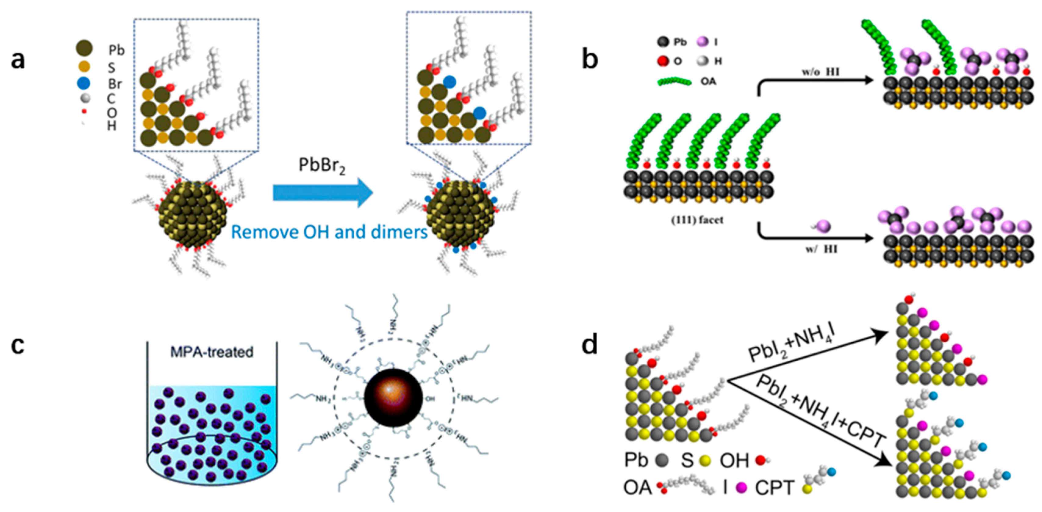
In 2014, Zherebetskyy et al. [30] reported that when PbO is used as a precursor, the hydroxyl (OH) group stays on the PbS (111) facet during synthesis. The formation process of the hydroxyl group on the (111) facet is shown in Figure 6. PbO is dissolved in hot oleic acid to form Pb(OA)2. When the (111) facet is formed, one OA in the Pb(OA)2 complex is separated from the Pb surface due to steric hindrance, the H2O molecule is dissociated to form an OH group on the Pb surface, and H+ combines with desorption OA to form oleic acid [30]. In addition, some studies also prove that hydroxyl can be brought in the process of PbS cleaning by an additional solvent [21], and water in the environment can also cause hydroxylation of PbS [33]. These hydroxyl groups (OH) are the source of PbS surface defect states, which seriously affect the properties of PbS and device performance.
In some studies, removing surface the hydroxyl group can effectively improve device efficiency. The main additives are listed in Table 3.
In 2020, Bin Sun et al. reported a surface reconstruction process to reduce the amount of OH [34]. During the synthesis of PbS, PbBr2 was injected into the solution when the solution was cooled to 60 °C (Figure 7a). Br competed with hydroxyl (-OH) to reduce the surface OH density [34]. Through ligand competition, the synthesized PbS has better monodispersity and the surface defect states are reduced. Jea Woong Jo et al. [22] proved that adding acid can enhance OA ligand shedding and HI selection can enhance OH removal by adding acid (Figure 7b). HI can also promote the formation of dense PbS CQD film through proton and I ions, remove organic residues, and better passivate the surface of CQDs. Mengfan Gu et al. [35] added MPA with two functional groups (thiols and carboxylic acids) to the butylamine solution at the end of ligand exchange and after vacuum drying. MPA in butylamine would replace OH and better passivate the surface of CQDs (Figure 7c). Debranjan Mandal et al. [20] used CPT and NH4I as additives to remove OH during ligand exchange and reduce aggregation between CQDs (Figure 7d).

4.4. Energy State Distribution Adjustment

The short-chain ligand is used in the ligand exchange process of CQDs, which increases carrier mobility, enhances surface passivation, and reduces trap states. However, the use of short-chain ligand will result in the aggregation of CQDs and poor size dispersion, which will seriously affect the film properties and device performance [36]. Ligand selection is the key to change the dispersion of CQDs. Some researchers mainly studied the removal of surface ligands while maintaining the monodispersity of CQDs. The main additives used are shown in Table 4.
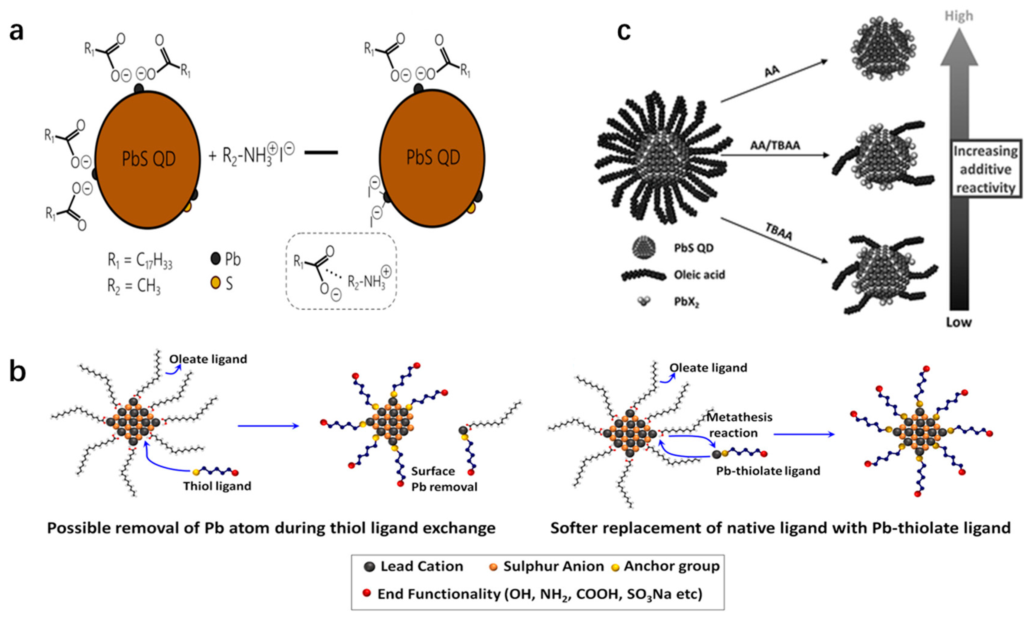
In order to introduce more iodine to the surface of CQDs without adverse effects of aggregation, Xinzheng Lan et al. [29] in 2016 treated CQDs with methylamine iodide (MAI) by using a much milder iodine source and the ion pairs formed by MA+-OA will further hinder the fusion between CQDs. The ligand exchange process is shown in Figure 8a. Aabhash Shestha et al. [37] used mercaptan ligand to explore the surface properties of PbS CQDs. The study found that if mercaptan was directly used for ligand exchange, Pb atoms on the surface of PbS would be removed, and the use of lead-thioate could enhance the removal of the OA ligand and maintain the stability of PbS CQDs (Figure 8b). Jea Woong Jo et al. [36] reported in 2017 that maintaining traces of OA on CQD surfaces helps improve equipment VOC. The weak acidity of tetrabutylammonium iodide (TBAA) favored the retention of OA ligands and inhibited the fusion and etching between CQDs (Figure 8c). The enhanced monodispersity inhibits band tails and energy disturbances, thus reducing the energy loss of devices [36]. Although the retention of OA leads to a decrease in carrier mobility and an increase in radiation compound loss, the carefully controlled proportional TBAA (AA:TBAA = 0.2:1) [36] can avoid a significant reduction in the JSC and fill factor (FF) of the equipment and improve the final equipment efficiency from 10.1% to 10.9%.

5. Conclusions

Our paper reviews the operating processes and additives used in solution phase ligand exchange for PbS CQDs. In solution phase ligand exchange, the long-chain ligand is replaced with the short-chain ligand, the surface is passivated, and the energy state distribution is narrowed. PbS is mainly composed of the (100) facet and (111) facet. For the (111) facet, both ligand removal and surface passivation are equal, while the surface of (100) is mainly passivation, supplemented by ligand removal. Surface hydroxyl groups produced during the synthesis process contribute to the properties of PbS, and the removal of hydroxyl groups from the surface has also been the subject of research in recent years. PbS CQDs are easy to aggregate, and increasing the monodispersity of particles improves device performance. This paper summarizes the characterization technology of CQD films and carrier dynamics. Currently, ligand research is primarily focused on improving electron transport, but little research has been conducted on improving hole transport. It should be noted that dimethylformamide (DMF) solution is the most polar solvent used to exchange ligands in the solution phase, and only a few polar solvents are chosen for the process. There should be continued research into the exchange of ligands in liquids.

Funding

The work was supported by a grant from the National Key Research and Development Program of China (Project 2022YFE0200200) and the National Natural Science Foundation of China (52072141).

Conflicts of Interest

The authors declare no conflict of interest.

References

  1. Nozik, A.J.; Beard, M.C.; Luther, J.M.; Law, M.; Ellingson, R.J.; Johnson, J.C. Semiconductor Quantum Dots and Quantum Dot Arrays and Applications of Multiple Exciton Generation to Third-Generation Photovoltaic Solar Cells. Chem. Rev. 2010, 110, 6873–6890. [Google Scholar] [CrossRef]
  2. Carey, G.H.; Abdelhady, A.L.; Ning, Z.; Thon, S.M.; Bakr, O.M.; Sargent, E.H. Colloidal Quantum Dot Solar Cells. Chem. Rev. 2015, 115, 12732–12763. [Google Scholar] [CrossRef] [PubMed]
  3. Keuleyan, S.; Lhuillier, E.; Brajuskovic, V.; Guyot-Sionnest, P. Mid-Infrared HgTe Colloidal Quantum Dot Photodetectors. Nat. Photonics 2011, 5, 489–493. [Google Scholar] [CrossRef]
  4. Dai, X.; Zhang, Z.; Jin, Y.; Niu, Y.; Cao, H.; Liang, X.; Chen, L.; Wang, J.; Peng, X. Solution-processed, high-performance light-emitting diodes based on quantum dots. Nature 2014, 515, 96–99. [Google Scholar] [CrossRef]
  5. García de Arquer, F.P.; Talapin, D.V.; Klimov, V.I.; Arakawa, Y.; Bayer, M.; Sargent, E.H. Semiconductor CQDs: Technological progress and future challenges. Science 2021, 373, eaaz8541. [Google Scholar] [CrossRef] [PubMed]
  6. Edward, H. Sargent. Infrared Quantum Dots. Adv. Mater. 2005, 17, 515–522. [Google Scholar]
  7. Choi, H.; Ko, J.H.; Kim, Y.H.; Jeong, S. Steric-Hindrance-Driven Shape Transition in PbS Quantum Dots: Understanding Size-Dependent Stability. J. Am. Chem. Soc. 2013, 135, 5278–5281. [Google Scholar] [CrossRef]
  8. Hines, M.A.; Scholes, G.D. Colloidal PbS Nanocrystals with Size-Tunable Near-Infrared Emission: Observation of Post-Synthesis Self-Narrowing of the Particle Size Distribution. Adv. Mater. 2003, 15, 1844–1849. [Google Scholar] [CrossRef]
  9. Weidman, M.C.; Beck, M.E.; Hoffman, R.S.; Prins, F.; Tisdale, W.A. Monodisperse, Air-Stable PbS Nanocrystals via Precursor Stoichiometry Control. ACS Nano 2014, 8, 6363–6371. [Google Scholar] [CrossRef]
  10. Beygi, H.; Sajjadi, S.A.; Babakhani, A.; Young, J.F.; van Veggel, F.C. Surface chemistry of as-synthesized and air-oxidized PbS Quantum Dots. Appl. Surf. Sci. 2018, 457, 1–10. [Google Scholar] [CrossRef]
  11. Shrestha, A.; Batmunkh, M.; Tricoli, A.; Qiao, S.Z.; Dai, S. Near-infrared Active Lead Chalcogenide Quantum Dots: Preparation, Post-Synthesis Ligand Exchange, and Applications in Solar Cells. Angew. Chem. Int. Ed. 2019, 58, 5202–5224. [Google Scholar] [CrossRef]
  12. Tang, J.; Kemp, K.W.; Hoogland, S.; Jeong, K.S.; Liu, H.; Levina, L.; Furukawa, M.; Wang, X.; Debnath, R.; Cha, D.; et al. Colloidal-quantum-dot photovoltaics using atomic-ligand passivation. Nat. Mater. 2011, 10, 765–771. [Google Scholar] [CrossRef]
  13. Carey, G.H.; Chou, K.W.; Yan, B.; Kirmani, A.R.; Amassian, A.; Sargent, E.H. Materials processing strategies for colloidal quantum dot solar cells: Advances, present-day limitations, and pathways to improvement. MRS Commun. 2013, 3, 83–90. [Google Scholar] [CrossRef]
  14. Fischer, A.; Rollny, L.; Pan, J.; Carey, G.H.; Thon, S.M.; Hoogland, S.; Voznyy, O.; Zhitomirsky, D.; Kim, J.Y.; Bakr, O.M.; et al. Directly Deposited Quantum Dot Solids Using a Colloidally Stable Nanoparticle Ink. Adv. Mater. 2013, 25, 5742–5749. [Google Scholar] [CrossRef]
  15. Wang, R.; Shang, Y.; Kanjanaboos, P.; Zhou, W.; Ning, Z.; Sargent, E.H. Colloidal quantum dot ligand engineering for high performance solar cells. Energy Environ. Sci. 2016, 9, 1130–1143. [Google Scholar] [CrossRef]
  16. Zhang, X.; Zhang, J.; Phuyal, D.; Du, J.; Tian, L.; Öberg, V.A.; Johansson, M.B.; Cappel, U.B.; Karis, O.; Liu, J.; et al. Inorganic CsPbI3 Perovskite Coating on PbS Quantum Dot for Highly Efficient and Stable Infrared Light Converting Solar Cells. Adv. Energy Mater. 2018, 8, 1702049. [Google Scholar] [CrossRef]
  17. Hu, L.; Lei, Q.; Guan, X.; Patterson, R.; Yuan, J.; Lin, C.; Kim, J.; Geng, X.; Younis, A.; Wu, X.; et al. Optimizing Surface Chemistry of PbS Colloidal Quantum Dot for Highly Efficient and Stable Solar Cells via Chemical Binding. Adv. Sci. 2021, 8, 2003138. [Google Scholar] [CrossRef] [PubMed]
  18. Jia, D.; Chen, J.; Zheng, S.; Phuyal, D.; Yu, M.; Tian, L.; Liu, J.; Karis, O.; Rensmo, H.; Johansson, E.M.J.; et al. Highly Stabilized Quantum Dot Ink for Efficient Infrared Light Absorbing Solar Cells. Adv. Energy Mater. 2019, 9, 1902809. [Google Scholar] [CrossRef]
  19. Liu, M.; Voznyy, O.; Sabatini, R.; de Arquer, F.P.G.; Munir, R.; Balawi, A.H.; Lan, X.; Fan, F.; Walters, G.; Kirmani, A.R.; et al. Hybrid organic–inorganic inks flatten the energy landscape in colloidal quantum dot solids. Nat. Mater. 2017, 16, 258–263. [Google Scholar] [CrossRef]
  20. Mandal, D.; Dambhare, N.V.; Rath, A.K. Reduction of Hydroxyl Traps and Improved Coupling for Efficient and Stable Quantum Dot Solar Cells. ACS Appl. Mater. Interfaces 2021, 13, 46549–46557. [Google Scholar] [CrossRef]
  21. Song, J.H.; Kim, T.; Park, T.; Jeong, S. Suppression of hydroxylation on the surface of colloidal quantum dots to enhance the open-circuit voltage of photovoltaics. J. Mater. Chem. A 2020, 8, 4844–4849. [Google Scholar] [CrossRef]
  22. Jo, J.W.; Choi, J.; García de Arquer, F.P.; Seifitokaldani, A.; Sun, B.; Kim, Y.; Ahn, H.; Fan, J.; Quintero-Bermudez, R.; Kim, J.; et al. Acid-Assisted Ligand Exchange Enhances Coupling in Colloidal Quantum Dot Solids. Nano Lett. 2018, 18, 4417–4423. [Google Scholar] [CrossRef] [PubMed]
  23. van Veggel, F.C.J.M. Near-Infrared CQDs and Their Delicate Synthesis, Challenging Characterization, and Exciting Potential Applications. Chem. Mater. 2014, 26, 111–122. [Google Scholar] [CrossRef]
  24. Ning, Z.; Gong, X.; Comin, R.; Walters, G.; Fan, F.; Voznyy, O.; Yassitepe, E.; Buin, A.; Hoogland, S.; Sargent, E.H. Quantum-Dot-in-Perovskite Solids. Nature 2015, 523, 324–328. [Google Scholar] [CrossRef] [PubMed]
  25. Mandal, D.; Goswami, P.N.; Rath, A.K. Thiol and Halometallate, Mutually Passivated Quantum Dot Ink for Photovoltaic Application. ACS Appl. Mater. Interfaces 2019, 11, 26100–26108. [Google Scholar] [CrossRef] [PubMed]
  26. Sun, B.; Ouellette, O.; de Arquer, F.P.G.; Voznyy, O.; Kim, Y.; Wei, M.; Proppe, A.H.; Saidaminov, M.I.; Xu, J.; Liu, M.; et al. Multibandgap quantum dot ensembles for solar-matched infrared energy harvesting. Nat. Commun. 2018, 9, 4003. [Google Scholar] [CrossRef] [PubMed]
  27. Fan, J.Z.; Andersen, N.T.; Biondi, M.; Todorović, P.; Sun, B.; Ouellette, O.; Abed, J.; Sagar, L.K.; Choi, M.-J.; Hoogland, S.; et al. Mixed Lead Halide Passivation of Quantum Dots. Adv. Mater. 2019, 31, 1904304. [Google Scholar] [CrossRef] [PubMed]
  28. Liu, M.; Che, F.; Sun, B.; Voznyy, O.; Proppe, A.; Munir, R.; Wei, M.; Quintero-Bermudez, R.; Hu, L.; Hoogland, S.; et al. Controlled Steric Hindrance Enables Efficient Ligand Exchange for Stable, Infrared-Bandgap Quantum Dot Inks. ACS Energy Lett. 2019, 4, 1225–1230. [Google Scholar] [CrossRef]
  29. Lan, X.; Voznyy, O.; de Arquer, F.P.G.; Liu, M.; Xu, J.; Proppe, A.H.; Walters, G.; Fan, F.; Tan, H.; Liu, M.; et al. 10.6% Certified Colloidal Quantum Dot Solar Cells via Solvent-Polarity-Engineered Halide Passivation. Nano Lett. 2016, 16, 4630–4634. [Google Scholar] [CrossRef]
  30. Zherebetskyy, D.; Scheele, M.; Zhang, Y.; Bronstein, N.; Thompson, C.; Britt, D.; Salmeron, M.; Alivisatos, P.; Wang, L.W. Hydroxylation of the surface of PbS nanocrystals passivated with oleic acid. Science 2014, 344, 1380–1384. [Google Scholar] [CrossRef]
  31. Choi, J.; Choi, M.J.; Kim, J.; Dinic, F.; Todorovic, P.; Sun, B.; Wei, M.; Baek, S.W.; Hoogland, S.; Garcia de Arquer, F.P.; et al. Stabilizing Surface Passivation Enables Stable Operation of Colloidal Quantum Dot Photovoltaic Devices at Maximum Power Point in an Air Ambient. Adv. Mater. 2020, 32, 1906497. [Google Scholar] [CrossRef] [PubMed]
  32. Kim, Y.; Che, F.; Jo, J.W.; Choi, J.; de Arquer, F.P.G.; Voznyy, O.; Sun, B.; Kim, J.; Choi, M.; Quintero-Bermudez, R.; et al. A Facet-Specific Quantum Dot Passivation Strategy for Colloid Management and Efficient Infrared Photovoltaics. Adv. Mater. 2019, 31, 1805580. [Google Scholar] [CrossRef] [PubMed]
  33. Shi, G.; Wang, H.; Zhang, Y.; Cheng, C.; Zhai, T.; Chen, B.; Liu, X.; Jono, R.; Mao, X.; Liu, Y.; et al. The effect of water on colloidal quantum dot solar cells. Nat. Commun. 2021, 12, 4381. [Google Scholar] [CrossRef] [PubMed]
  34. Sun, B.; Vafaie, M.; Levina, L.; Wei, M.; Dong, Y.; Gao, Y.; Kung, H.T.; Biondi, M.; Proppe, A.H.; Chen, B.; et al. Ligand-Assisted Reconstruction of Colloidal Quantum Dots Decreases Trap State Density. Nano Lett. 2020, 20, 3694–3702. [Google Scholar] [CrossRef] [PubMed]
  35. Gu, M.; Wang, Y.; Yang, F.; Lu, K.; Xue, Y.; Wu, T.; Fang, H.; Zhou, S.; Zhang, Y.; Ling, X.; et al. Stable PbS Quantum Dot Ink for Efficient Solar Cells by Solution-Phase Ligand Engineering. J. Mater. Chem. A 2019, 7, 15951–15959. [Google Scholar] [CrossRef]
  36. Jo, J.W.; Kim, Y.; Choi, J.; de Arquer, F.P.G.; Walters, G.; Sun, B.; Ouellette, O.; Kim, J.; Proppe, A.H.; Quintero-Bermudez, R.; et al. Enhanced Open-Circuit Voltage in Colloidal Quantum Dot Photovoltaics via Reactivity-Controlled Solution-Phase Ligand Exchange. Adv. Mater. 2017, 29, 1703627. [Google Scholar] [CrossRef]
  37. Shestha, A.; Yin, Y.; Andersson, G.G.; Spooner, N.A.; Qiao, S.; Dai, S. Versatile PbS Quantum Dot Ligand Exchange Systems in the Presence of Pb-Thiolates. Small 2017, 13, 1602956. [Google Scholar] [CrossRef]
Figure 1. (a) Schematic diagram of solid-state ligand exchange and film fabrication. CQDs were first deposited on substrate by spin coating, then short organic ligands in solvent were dropped on CQD film to replace the long alkyl chains. After that, protic solvent was used to rinse the exchanged ligands. (b) Schematic diagram of solution phase ligand exchange and film fabrication. Firstly, long alkyl chain ligands were exchanged into short organic thiol ligands in solution. One-step spin coating process was then used for film fabrication. Reprinted from reference [15]. Copyright 2016, The Royal Society of Chemistry.
Coatings 14 00761 g001
Figure 2. Schematic diagram of solution phase halide ligand exchange. First, halide was used to replace all organic ligands in solution. One-step spin coating was used for film fabrication, followed by an annealing process. The image inside shows the ligand exchange process. Reprinted from reference [15]. Copyright 2016 The Royal Society of Chemistry.
Coatings 14 00761 g002
Figure 4. (a). XPS O 1s spectra of PbI2-passivated CQD solids before and after AM1.5 illumination for 30 h in air. Dashed lines indicate the different chemical bonding states of oxygen (529.3 eV for PbO, 530.9 eV for PbSO3, and 531.7 eV for PbSO4). (b). Schematic illustration of the degradation process of PbI2-passivated PbS CQD solids by oxidation. Reprinted from reference [31]. Copyright 2020, WILEY-VCH.
Coatings 14 00761 g004
Figure 5. (100) facet passivation. (a). KI-shielded PbS CQD solids. Reprinted from reference [31]. Copyright 2020 WILEY-VCH. (b). The hypothetical effects of ligand exchange processes in the three types of solutions and oxygen attack on ligand exchanged PbS CQDs. (The compared atoms are marked by the arrows during the ligand exchange procedure.). Reprinted from reference [17]. Copyright 2020 WILEY-VCH. (c). Lead-halide-passivated CQDs with Na-passivation on the (100) facets. Reprinted from reference [32]. Copyright 2019, WILEY-VCH.
Coatings 14 00761 g005
Figure 6. Multistep process for building up the (111) facets of a PbS NC. (A) Pb(OA)2···H2O precursors approach the nonpolar and stoichiometric (111) facets. (B) Pb ions bind to surface vacancies. (C) One of the two OA in each Pb(OA)2···H2O complex is removed because of steric effects, and the water molecule dissociates to provide an OH group to the surface and H+ for desorbing OA. (D) The desorbed OAH molecules dimerize in the solvent. Reprinted from reference [30]. Copyright 2014, The American Association for the Advancement of Science.
Coatings 14 00761 g006
Figure 7. Schematic illustration of hydroxyl (OH) removal. (a). PbBr2 in-synthesis reconstruction. Reprinted from reference [34]. Copyright 2020 American Chemical Society. (b). HI-assisted solution phase ligand exchange on the (111) facets of PbS CQDs. Reprinted from reference [22]. Copyright 2018 American Chemical Society. (c). MPA-treated PbS QD ink. Reprinted from reference [35]. Copyright 2019 The Royal Society of Chemistry. (d). CPT and NH4I passivate (111) facets. Reprinted from reference [20]. Copyright 2021, American Chemical Society.
Coatings 14 00761 g007
Figure 8. (a). Ligand shell changes following MAI treatment. DMF-solvated I ligands partially replace long-chain oleate ligands on the CQD surface. An additional shell of MA+–OA ion pairs is formed as a result of the electrostatic attraction, thereby offering steric hindrance in addition to tightly bound oleates remaining on the surface. Reprinted from reference [29]. Copyright 2016 American Chemical Society. (b). Schematic illustration for the ligand exchange using only thiol as exchanging ligand, and Pb-thiolate as the exchanging ligand. Reprinted from reference [37]. Copyright 2016 WILEY-VCH. (c). Schematic illustration of the control by mixing AA and TBAA reagents. Reprinted from reference [36]. Copyright 2017, WILEY-VCH.
Coatings 14 00761 g008
Table 1. The additives and chemical equations used for the purpose of ligand removal.
AdditivesChemical Equations
NH4Ac and PbX2 (Br, I) PbS-OA   CQD + PbX 2 ( Br ,   I )   N H 4 A c PbS-PbX2 (Br, I) CQD
NH4Ac, PbI2 and CsI PbS-OA   CQD + PbI 2 + CsI   N H 4 A c PbS-CsPbI3-P CQD
Carboxylates (formate, acetate and propionate)PbS-OA CQD + PbI2 + RCOO PbS-PbI2 + RCOO CQD
CPT, NH4I, and PbX2 (Br, I)PbS-OA CQD + CPT + NH4I + PbX2 (Br, I) PbS-CPT + PbX2 (Br, I) CQD
NH4IPbS-OA CQD + AI PbS-AI CQD
NaAc and PbX2 (Cl, Br, I)PbS-OA CQD + NaAc + PbX2 (Cl, Br, I) PbS-NaAc + PbX2 (Cl, Br, I) CQD
Table 2. The additives and chemical equations for (100) facet passivation.
AdditivesChemical Equations
KI PbS-OA   CQD + PbX 2   ( Br ,   I ) + KI   N H 4 A c PbS-KI + PbX2 (Br, I) CQD
KI3 PbS-OA   CQD + PbX 2 ( Br ,   I ) + KI 3   N H 4 A c PbS-KI3 + PbX2 (Br, I) CQD
NaAcPbS-OA CQD + PbX2 (Br, I) + NaAc PbS-NaAc + PbX2 (Br, I) CQD
Table 3. The additives and chemical equations for hydroxyl (-OH) removal.
AdditivesChemical Equations
PbBr2 was added to the synthesis processPbS-OH CQD + PbBr2 PbS-PbBr2 CQD
PbS-OA   CQD + PbX 2   ( Br ,   I )   N H 4 A c PbS-PbX2 (Br, I) CQD
HIPbS-OA + OH CQD + HI + PbX2 (Br, I) + NaAc PbS-PbX2 (Br, I) + HI CQD
CPT and NH4IPbS-OA + OH CQD + CPT + PbX2 (Br, I) + NH4I PbS-CPT + PbX2 (Br, I) CQD
MPA was added to butylaminePbS-OA + OH   CQD + MPA + PbI 2   N H 4 A c PbS-MPA + PbI2 CQD
Table 4. The additives and chemical equations for the energy distribution of carriers are regulated.
AdditivesChemical Equations
MAIPbS-OA CQD + MAI + TBAI PbS-MAI + TBAI CQD
Pb-thiolatePbS-OA CQD + Pb-MESNA(GSH) PbS-MESNA(GSH) CQD
NH4Ac and TBAA PbS-OA   CQD + PbX 2   ( Br ,   I )   N H 4 A c   +   T B A A PbS-OA + PbX2 (Br, I) CQD
Disclaimer/Publisher’s Note: The statements, opinions and data contained in all publications are solely those of the individual author(s) and contributor(s) and not of MDPI and/or the editor(s). MDPI and/or the editor(s) disclaim responsibility for any injury to people or property resulting from any ideas, methods, instructions or products referred to in the content.