Article

Friction and Wear Behavior of 3D-Printed Inconel 718 Alloy under Dry Sliding Conditions

by
Ioannis Karagiannidis
1,*,
Athanasios Tzanis
2,3,*,
Dirk Drees
4,
Lais Lopes
4,
Georgios Chondrakis
2,
Maria Myrto Dardavila
3,
Emmanuel Georgiou
1 and
Angelos Koutsomichalis
1
1
Laboratory of Materials, Hellenic Airforce Academy, Dekelia Air Base, 13671 Acharnes, Attikis, Greece
2
Laboratory of Materials, Electronics Depot-R&T Centre, 16562 Glyfada, Attikis, Greece
3
Laboratory of General Chemistry, School of Chemical Engineering, National Technical University of Athens, 15772 Zografou, Attikis, Greece
4
Falex Tribology NV, Wingepark 23B, 3110 Rotselaar, Belgium
*
Authors to whom correspondence should be addressed.
Coatings 2024, 14(8), 1029; https://doi.org/10.3390/coatings14081029
Submission received: 30 May 2024 / Revised: 4 August 2024 / Accepted: 8 August 2024 / Published: 13 August 2024
(This article belongs to the Special Issue Surface Engineering Processes for Reducing Friction and Wear)

Abstract

:
Tailor-made materials used for advanced applications are nowadays of great research interest in various industrial and technological fields, ranging from aerospace and automotive applications to consumer goods and biomedical components. In the present research, Inconel 718 superalloy specimens were fabricated by the selective laser melting (SLM) technique. Structural characterization of the 3D-printed samples showed that they consisted of γ solid solution along with spherical carbide particles. To explore the applicability of these materials in abrasive tribological applications, reciprocating sliding tests were performed under dry conditions versus an Al2O3 counter-body. A 3D representation (triboscopy) of the tangential force during each sliding cycle was carried out in order to obtain better insight on the evolution of friction and to visualize localized tribological phenomena. Quantification of wear was performed with confocal microscopy and the wear mechanisms were analyzed with SEM and EDS techniques. Furthermore, the effect of surface finishing (as-printed and polished) on friction and wear were also investigated, and a comparison with other industrial materials is also included to evaluate the applicability of these alloys. The results indicated that surface finishing had an effect on friction during the run-in stage, whereas in steady-state conditions, no significant differences were observed between the as-printed and polished specimens. In all cases, the main wear mechanisms observed were a mixture of two-body and three-body abrasion, along with oxidative wear (indicated by the formation of an oxide-based tribo-layer).

1. Introduction

Additive manufacturing (AM) has emerged as a modern manufacturing method since its introduction in the late 1990s [1]. Despite being relatively young, AM has rapidly evolved, becoming a versatile technique applicable to various materials [2]. Nowadays, it is widely recognized as a promising approach for fabricating complex mechanical components across diverse industrial sectors, including aerospace, automotive, civil engineering, and biomedical fields [3]. Selective laser melting (SLM) has gained prominence among AM methods for its ability to produce intricate metallic parts [4]. However, a notable drawback of SLM is the presence of defects, often necessitating post-processing thermal treatments [5].
However, despite these existing drawbacks, SLM metal printing has revolutionized the materials manufacturing industry, particularly in aeronautics, by enabling the creation of lightweight, high-strength components that are crucial for enhancing performance, fuel efficiency, and safety [6]. On a daily basis, engineers utilize this technology to design and produce components with challenging geometries and improved mechanical properties, while at the same time achieving a reduction in weight without compromising structural integrity [7]. Additionally, it facilitates rapid prototyping and iteration, accelerating innovation and reducing development time for new aerospace components [8], whereas at the same time, it offers the flexibility to produce on-demand and low-volume parts, eliminating the need for expensive tooling and long lead times associated with traditional manufacturing methods [9]. These features are of vital importance, especially for the aeronautical industry, where sourcing expensive spare parts can be challenging (e.g., due to aging phenomena and/or environmental degradation) and costly.
Among the various aeronautical materials, Inconel alloys hold a prominent position as they combine high temperature [10] and corrosion [11] resistance with excellent mechanical characteristics [12]. Thus, metal 3D-printing Inconel alloy components have great potential in the aeronautical industry as they offer design flexibility and enhance manufacturing versatility and efficiency. The most widely used Inconel alloy in AM is 718, as it finds applications in aircrafts, gas turbines, turbocharger rotors, and various other corrosive and structural contexts where temperatures reach up to approximately 700 °C [13]. The high research interest in this alloy is confirmed by the increased number of publications, focusing mainly on its mechanical properties, as explained in the review article of Hosseini and Popovich [13]. Extensive work has also been performed on the corrosion behavior of this alloy produced with different AM methods and tested under different environments and temperatures [14,15,16,17,18]. In addition, AM Inconel alloys are increasingly used in tribological applications [19]. Indeed, there are several recent articles on this topic concerning the tribological behavior of 3D-printed 718 Inconel alloys [20,21,22,23,24,25,26].
In these articles, the friction and wear of this material are evaluated under different conditions, including dry wear versus hard abrasive carbides [20], high temperatures [21], and lubricated environments [22]. The performance of the alloy was linked to both its intrinsic characteristics and structure, which are determined by the manufacturing conditions [23], as well as its ability to form oxide-based tribo-layers and debris in the contacting interface [24]. The presence of corrosive environments was also reported [25] to significantly affect and accelerate material loss, mainly due to the synergism between wear and corrosion phenomena. Currently, further optimization of tribological properties of AM 718 Inconel alloys is explored by performing various post-processing treatments such as nitriding [26], etc. However, there is still a lack of comprehensive information regarding the tribological performance of these alloys, especially in SLM-manufactured components. The main issue stems from the fact that friction and wear are systemic properties that depend on the contact geometry and conditions, counter-body, environment, etc. This means that results cannot be extrapolated from one tribo-system to another. Thus, this research article aims to establish a structure–property relationship and understand dominant wear mechanisms under dry reciprocating conditions, against an oxide abrasive countermaterial. The influence of surface finishing was also considered and studied via triboscopy analysis, whereas a comparison with other widely used industrial materials was also included to provide a direct tribological ranking of materials under the test conditions.

2. Materials and Methods

A commercially supplied Inconel 718 alloy powder, consisting of particles with spherical morphology and size ranging between 15 μm and 45 μm, was utilized to fabricate rectangular-shaped specimens (30 mm × 30 mm × 2 mm) with the SLM technique.
The SLM apparatus utilized for the additive manufacturing procedure was a Print Sharp 150, equipped with a single-mode fiber laser which operates in the IR region, at a power of 120 W, and a scanning speed of 1200 mm/s. During the manufacturing process, the chamber operated under an inert nitrogen atmosphere, while the building platform temperature was held constant at 60 °C. The residual oxygen level was kept below 500 ppm, as stated by the technical capabilities of the apparatus. The layer thickness and the hatch spacing were 30 μm and 50 μm, respectively. The scanning strategy that was followed was stripes with horizontal orientation. The specimens were not subjected to subsequent heat treatment.
To investigate the microstructure of the material, a metallographic sample was prepared from cross-sections of the fabricated SLM specimens by grinding with SiC papers and polishing with 3 μm and 1 μm diamond suspension, followed by 0.1 μm aluminum oxide polishing. Finally, the metallographic sample was etched by swabbing with a chemical solution consisting of 60 mL of lactic acid, 20 mL of HNO3, and 10 mL of HF.
The microstructure was investigated with optical microscopy (OM) and scanning electron microscopy (SEM, JEOL IT500LV, Tokyo, Japan), while the stoichiometry was analyzed with an energy-dispersive spectrometer (EDS, Oxford Instruments X-Max Extreme, Oxford, UK). The crystallographic structure was studied by means of the X-ray diffraction technique (XRD, Bruker D8 Advance, Ettlingen, Germany), operating with a CuKα X-ray source (λ = 0.154 nm) and a step size of 0.1°.
Vickers microhardness measurements were performed by applying a load of 1 kg for a duration of 12 s with a Duramin-5 (Struers, Copenhagen, Denmark) apparatus. The average microhardness value was obtained from five indentations.
A ball-on-disk tribometer (BASALT-N2, TETRA, Ilmenau, Germany) was utilized to carry out the friction and wear reciprocating sliding experiments in ambient conditions. An Al2O3 ball (hardness 2000 HV0.5, Rα = 0.2 μm) with a diameter of 6 mm was utilized as a counter-body. The applied load was set at 10 N, the stroke length at 2 mm, and the speed at 20 mm/s. On each track, the friction experiment was repeated for 10,000 cycles. For the tribo-tests, two sets of surface finishing were considered; one was the as-prepared (Samples “A” and “B”) and the other with surface finishing with SiC papers of 120, 320, 400, 600, 800, and 1200 grit (Samples “C” to “F”). For the polished specimens, four different samples were considered, and, on each sample, duplicate tribo-tests were performed. In addition, for the as-prepared specimens, two samples were evaluated again by carrying out duplicate tests.
To explore the applicability of the 3D-printed Inconel alloys, triplicate tribological tests were carried out for the same experimental conditions in order to have a direct and meaningful comparison with reference materials, namely commercially supplied 100Cr6 bearing steel, commercially supplied Ag-coated steel, electroless Ni-P-coated steel [27], electrodeposited hard Cr and Cr(III)-coated steels [27], and atmospheric plasma sprayed titania and chromia coatings [28].
A NanoFocus μSurf Explorer (NanoFocus AG, Oberhausen, Germany) confocal microscope was utilized to measure the surface roughness of the specimens prior to the friction test, as well as to carry out a subsequent wear depth analysis. Between 200 and 400 confocal images per second were acquired with a ×10 magnifying lens in order to fully resolve the topographical features, which were in the micrometer range. Finally, the wear mechanisms were analyzed with the SEM and EDS configuration described previously.

3. Results and Discussion

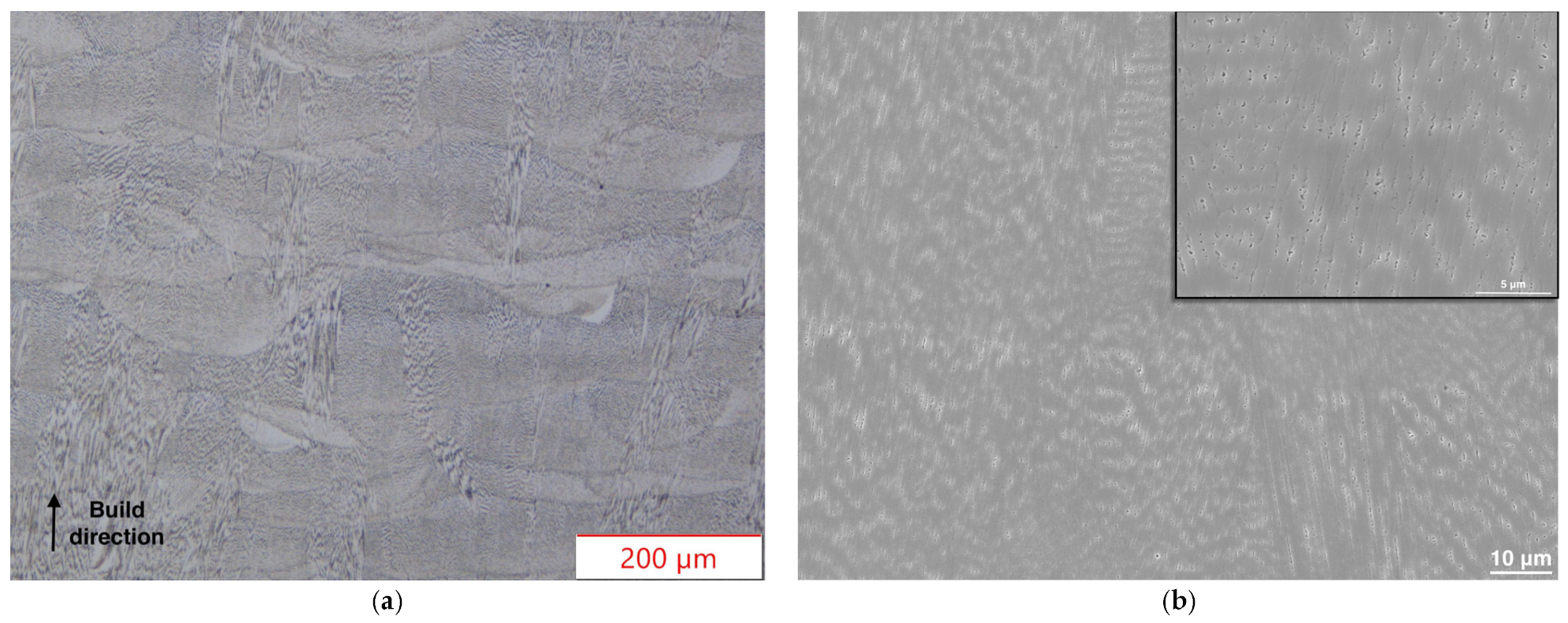
3.1. Specimen Characterization

The fabricated specimens have the typical stoichiometric composition (wt. %), which is presented in Table 1 along with the nominal composition of the nickel-based 718 superalloy according to aerospace material specification (AMS) 5662.
In Figure 1a, the OM microstructure of the specimens is represented after chemical etching. Melt pool boundaries, as well as columnar grains, can be seen in the OM micrograph, as it was also observed in as-prepared specimens by other scientific groups [29,30,31,32]. Black regions in Figure 1b correspond to carbides (likely of MC type), Laves phase, and defects (microporosity and non-fused regions) [29,30,32,33].
The microhardness of the material was measured at 284 ± 15 HV, the typical value for the as-prepared AM 718 alloy [31,32].
As it is shown in the XRD spectrum in Figure 2, the as-prepared specimens show the diffracting peaks (111), (200), (220), (311), and (222) that are attributed to the γ solid solution [29].
SEM analysis did not reveal the strengthening phases of γ′ and γ″ particles due to either their nanometer-scale size or their very small quantity. Also, from the diffractogram it can be derived that the γ′ and γ″ phases were not distinguishable or detected due to the overlapping of their corresponding peaks with the ones of the γ phase and/or due to their concentration being below the detection limit of this method [34], possibly indicating a very small quantity in the prepared samples. Furthermore, according to the literature, the decreased microhardness values show that no strengthening mechanism is achieved. The aforementioned statements point towards the fact that the γ’ and γ″ phases were either in very small quantity or not present in the as-prepared samples [33,35].
The surface roughness was measured both for the as-prepared and for the polished specimens prior to the friction experiment. Indicative 3D surface topographies are shown in Figure 3.
The as-prepared specimens exhibit a mean surface roughness of 15.8 μm, whereas the polished ones show a much-reduced roughness with an average value of 1.56 μm.
The skewness and kurtosis parameters were derived from the surface roughness analysis. The as-prepared specimens exhibit a height distribution which was above the mean plane and almost normal, as it was derived from the skewness parameter Ssk and the kurtosis parameter Sku, which were −0.165 and 3.63, respectively. The values of Ssk and Sku for the polished specimens were −0.029 and 4.15, respectively, showing an almost symmetrical form around the mean plane and leptokurtic (spiked) height distribution.

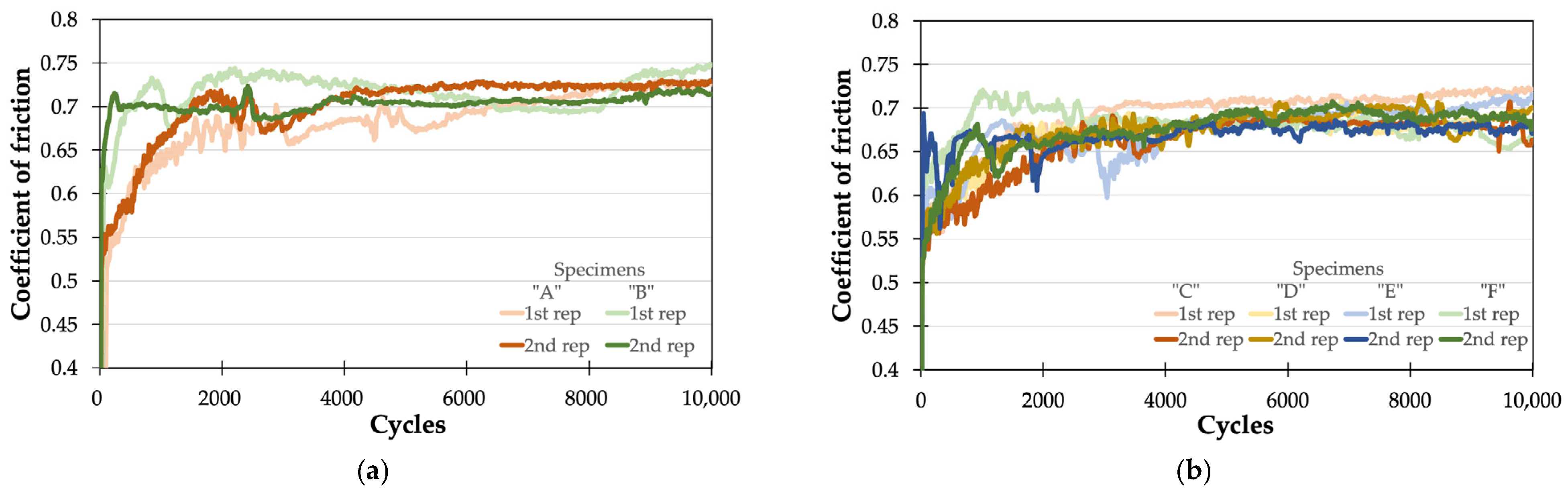
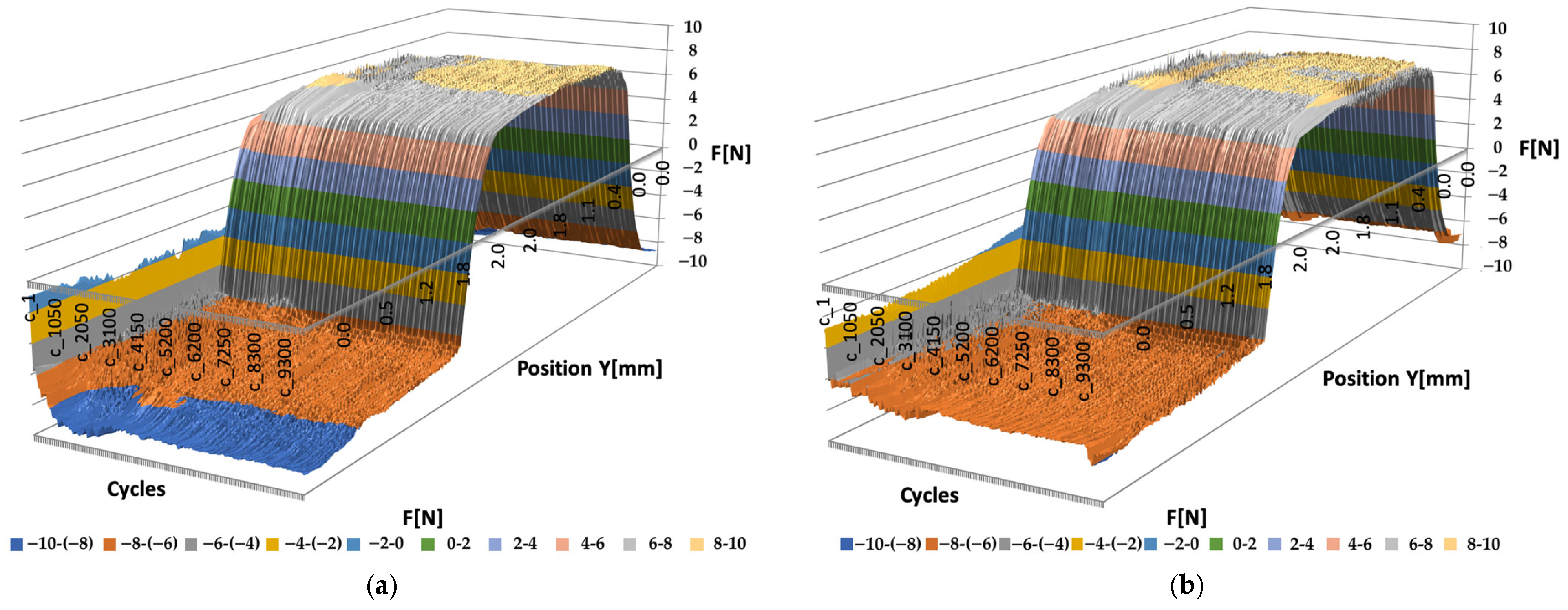
3.2. Triboscopical Performance
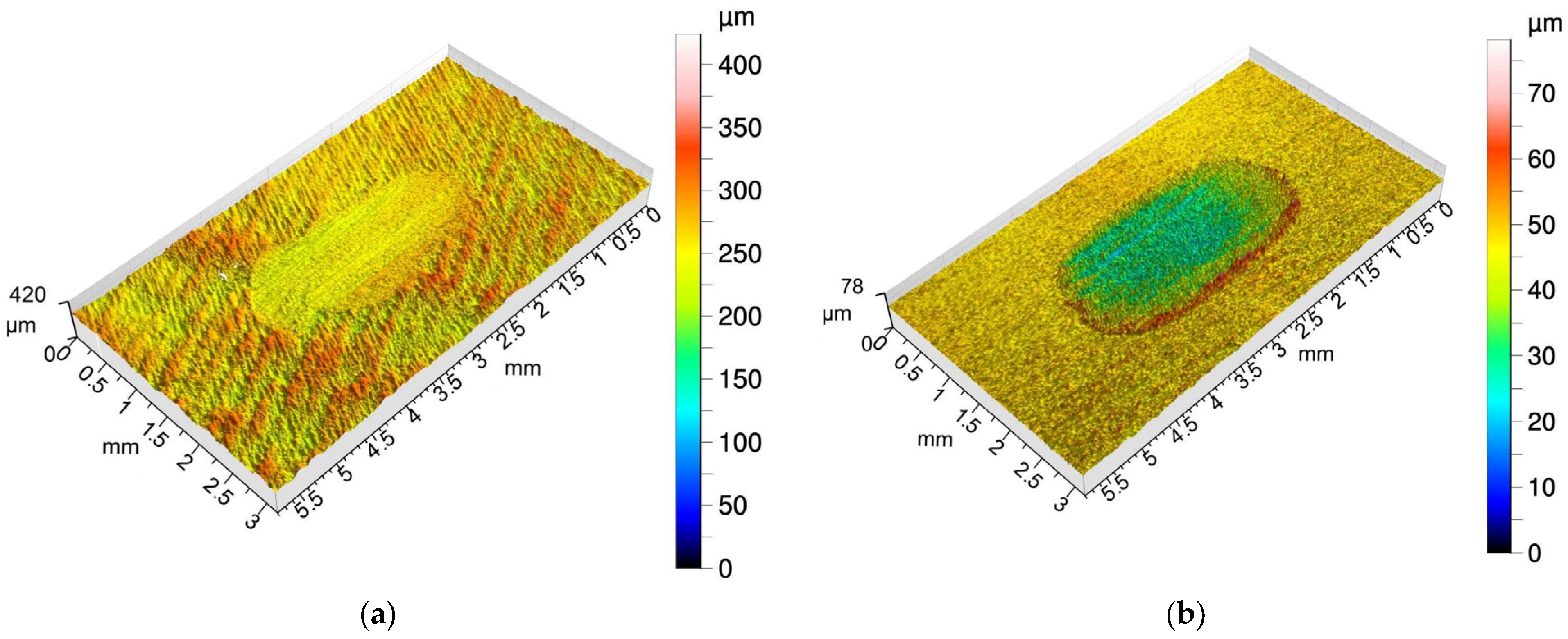
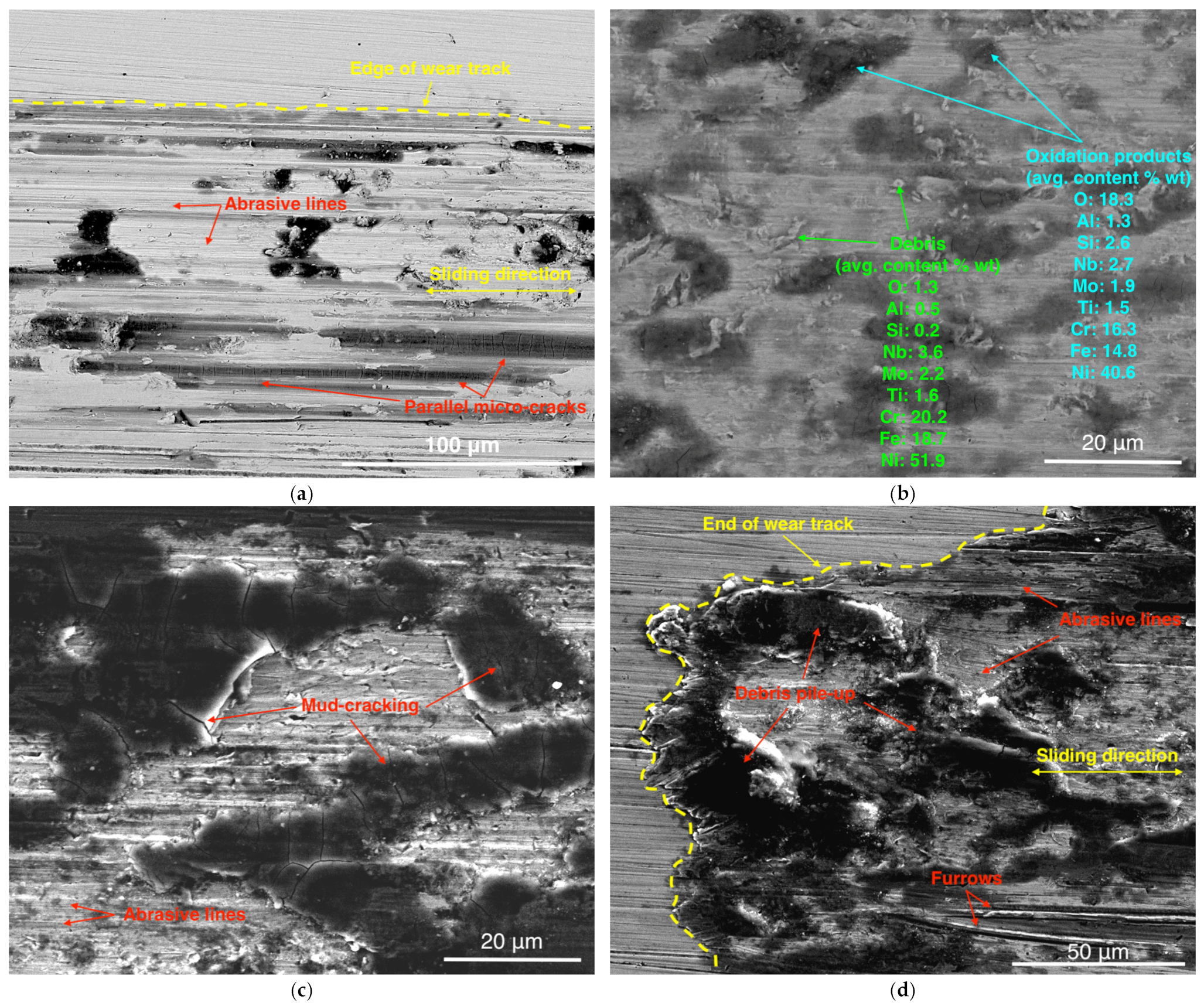
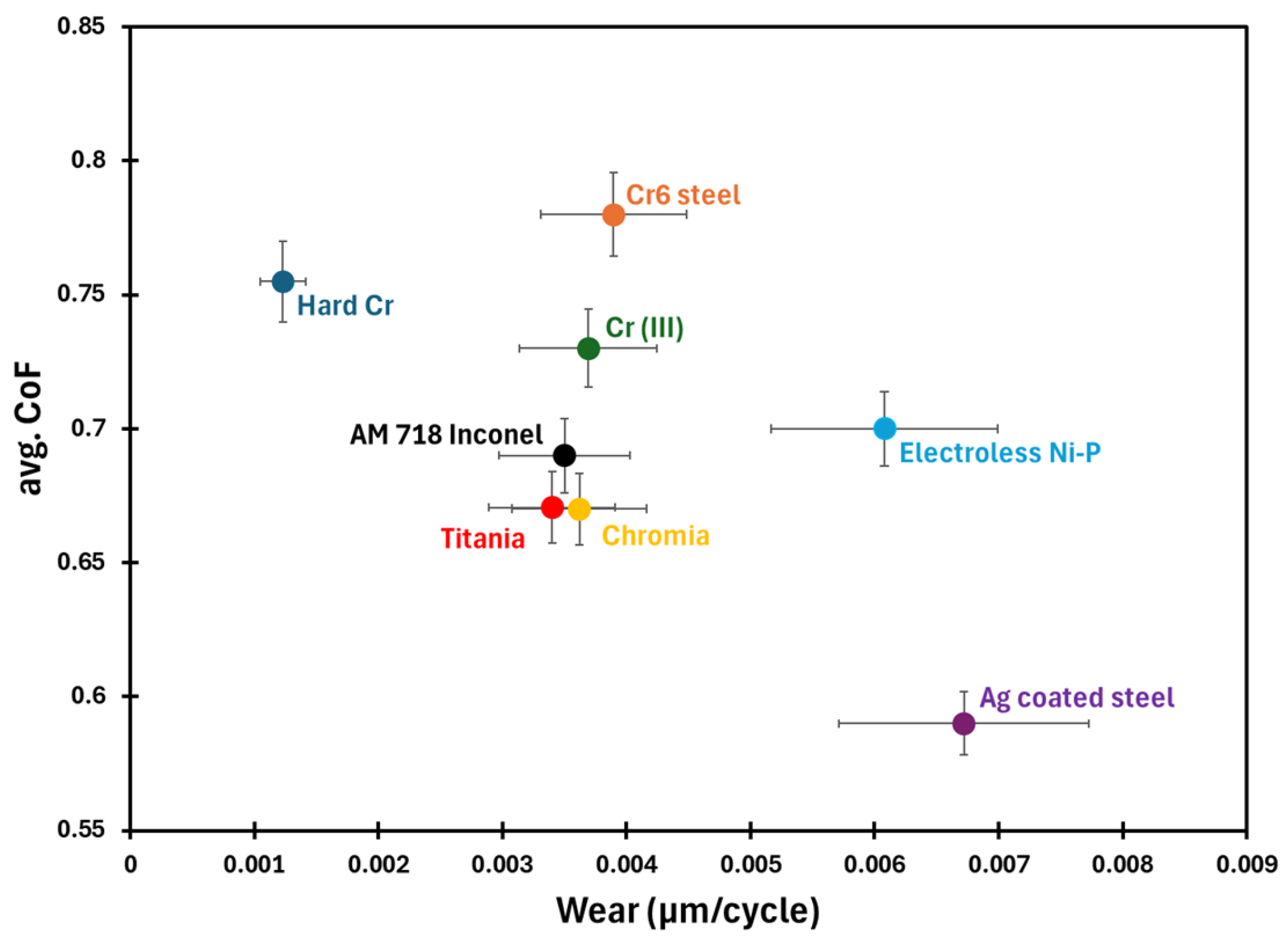
The evolution of the coefficient of friction (COF) μ per cycle is depicted in Figure 4a for the as-prepared “A” and “B” specimens and in Figure 4b for the polished “C” to “F” specimens.
The COF of the polished specimens shows a smoother evolution per cycle compared to the as-prepared specimens, especially during the run-in stage. The higher fluctuation in the COF of the as-prepared samples is mainly ascribed to localized changes and/or reduction of the initial asperities [36], and to the generation of debris at the tribo-contact. However, the nature of run-in and COF fluctuations is often much more complicated as other factors such as sub-surface deformation and localized heating-up and oxidation are also associated [37]. To draw safe conclusions, post analysis of the wear tracks was performed to identify surface interactions and will be presented later on.
The as-prepared specimens presented an average COF value of μ = 0.709 ± 0.016, while the polished specimens had an average COF value of μ = 0.689 ± 0.019. For both types of specimens, the very low standard deviation from the average COF values shows a very good repeatability between the experiments. Furthermore, the two types of specimens show an almost identical steady-state value of COF.
In order to further evaluate the triboscopical properties of the two types of specimens, the evolution of friction force versus the displacement is plotted for each sliding cycle. Characteristic 3D curves for both types are presented in Figure 5.
Although both the as-prepared and the polished specimens have the same steady-state friction COF, they exhibit quite different transition behavior regarding the friction force. The early intense fluctuating phenomena are also depicted in the 3D triboscopical curve of the as-prepared specimen (Figure 5a). Furthermore, emphasizing at the as-prepared specimen, it was observed that peaks of friction force appear at the edges of the cycles, appearing in Figure 5a with blue color representing forces between −10 and −8 N. This increase in friction force is indicative of debris pile-up in the edges of the sliding track, which result in adhesion phenomena with the alumina counter-body. The high amount of debris can be ascribed to the much higher average roughness (one order of magnitude) and to the height distribution of the as-prepared specimen being skewed above the mean plane.

3.3. Wear Behavior

Indicative 3D confocal microscopy images for the as-prepared and polished specimens are presented in Figure 6.
The wear track of the as-prepared specimens exhibits a mean volume loss of 0.069 mm3 and a mean depth from the surface of about 17.2 μm. Material pile-up at the edges of the wear track is observed by confocal microscopy and shows a mean volume above the surface of the specimen of about 0.023 mm3 and a mean height above the surface of about 12.6 μm. In contrast, the wear tracks of the polished specimens show a mean volume loss of 0.03 mm3 and a mean depth from the surface of about 7.7 μm. The debris pile-up shows a mean volume and height above the surface of about 0.006 mm3 and 3.3 μm, respectively. It is deduced that an almost doubled wear loss accompanies the as-prepared specimens. As for the polished specimens, it should also be noted that the mean maximum values of depth (43.8 ± 7.3 μm) and height (30.8 ± 5.9 μm) distances from the surface show a good homogeneity. This case is not observed for the as-prepared specimens. In particular, the wear track in Figure 6a exhibits a maximum depth from the surface of about 250 μm and a maximum height of 166 μm, while the average values of the as-prepared specimens are 139.1 ± 77.5 μm and 93.4 ± 49.4 μm, respectively. This fact shows that the produced debris from the friction experiment are of higher amount and larger in size, and can damage the surface following three-body abrasion.
In order to obtain a more precise understanding of the wear behavior of the polished specimens in particular, SEM analysis was conducted at their corresponding wear tracks. Indicative micrographs are depicted in Figure 7.
Figure 7a is a backscatter electron micrograph near the edge of the wear track. Abrasive lines from the counter-body are clearly depicted in the wear groove. Areas of black color indicate the presence of lighter elements present in the surface. At such elongated black areas, the formation of parallel micro-cracks is observed, which are perpendicular to the sliding direction, indicating the growth of excessive strains during the reciprocating counter-body motion [38].
Figure 7b is a higher-magnification backscatter micrograph at the black areas spotted. EDS analysis performed at these black areas revealed a high increase in the oxygen concentration and a slight increase in aluminum content, indicating the formation of a mixture of oxides. In the secondary electron micrograph of Figure 7c, it can be observed that these oxidation products exhibit also a mud-cracking morphology [39] and appear to be adhered on the specimen’s surface. The formation of oxides and their adhesion on the specimen’s surface indicate elevated temperatures during the reciprocating movement of the counter-body [40].
In the secondary electron image of Figure 7d, it can be observed that the specimen has undergone plastic deformation with material removal. There is debris pile-up at the end of the wear track. Also, abrasive lines are apparent in the wear groove, but also large furrows that point to the edge and have formed due to debris abrasion, indicative of the three-body abrasion wear mechanism.
To explore the applicability of the AM 718 Inconel alloy under dry sliding abrasive conditions, the friction (in steady-state conditions) and wear per cycle are compared to different reference materials used in tribological applications and tested under the same operating conditions (Figure 8). In terms of wear resistance, the AM printed alloy has similar wear resistance to the ceramic-based chromia- and titania-sprayed coatings which are made especially for abrasive applications, whereas it has superior wear resistance to conventional metallic-based materials and coatings. Only hard chrome coatings have clearly higher resistance, but these coatings are being restricted by the European Commission due to the negative environmental impact of hard chromium plating processes [41]. Further, optimization of AM 718 Inconel alloy can potentially be an alternative to hard chrome coatings. Concerning friction, the majority of these materials have a high COF, which is due to the aggressive abrasive conditions, which result in the generation of debris particles in the tribo-contact. Indeed, it is known that the higher the amount of debris generated in the contact, the higher the friction [42]. Therefore, lubrication and/or further surface modification seem essential in order to reduce friction.
Apart from lubrication, another approach to enhancing the tribological properties of additive manufactured (AM) materials is through advanced post-processing surface treatments. Recent review articles [43,44,45,46] have demonstrated that thermal, mechanical, and chemical post-treatments can significantly improve the surface properties of AM metallic parts. These enhancements are achieved by reducing surface roughness and residual stresses, altering the microstructure, and eliminating structural defects in the surface layers. A wide variety of surface post-treatments are now utilized, categorized by the intrinsic characteristics of the applied technology and the resultant effects on the AM part’s surface [46]. These treatments include processes with and without material removal, coatings, and hybrid treatments. For AM post-processing of the 718 Inconel alloy, current notable treatments include heat treatments [47,48], shot peening [49], laser shock peening [50], finish machining (FM) [51], drag finishing (DF) [51], and vibratory surface finishing (VSF) [51]. When optimized processing conditions are applied [47,48,50,51], improvements in friction and wear performance can be achieved. However, the success and impact of these post-processes also depend on the tribo-chemistry, contact conditions, contact geometry, and environment of the tribo-system, as tribology is a systemic property [52]. Therefore, further research into post-processes and their influence on friction and wear is crucial for expanding the application of AM in industries where high-performance materials are essential.

4. Conclusions

The triboscopical properties of both as-prepared and polished SLM Inconel 718 specimens were examined in the present work.
OM, SEM, EDS, and XRD analysis show that the specimens have the typical microstructure and stoichiometry of an as-prepared AM nickel-based 718 superalloy. It should be noted that no further heat treatment was applied to the specimens. Confocal microscopy verified the finer surface roughness of the polished specimens.
Both types of specimens exhibit almost the same values of COF, namely 0.709 and 0.689 for the as-prepared and polished specimens, respectively. In comparison to the as-prepared specimens, the COF of the polished ones shows a relatively smoother transition during the run-in stage. Also, an almost halved wear volume was recorded for the polished specimens. From the SEM-EDS analysis, it was possible to address the existence of three wear mechanisms, namely abrasive (both two-body and three-body), adhesive, and oxidative wear.
Depending on the intended performance of the final product, as-prepared AM Inconel 718 materials are potential candidates for utilization in wear-resistant applications.
Surface polishing had an influence during the run-in stage, mainly due to topographical changes and the subsequent formation of debris in the tribo-contact. However, depending on the selected post-treatment, various topographical and/or structural changes can occur, and the surface properties may vary considerably. Thus, further research is needed to establish a better correlation between surface finishing processes such as remelting, shot or laser peening, etc., and their influence on the microstructure and properties (mechanical and/or electrochemical) of this AM alloy.

Author Contributions

Formal analysis, I.K., A.T. and A.K.; investigation, I.K., A.T., D.D., L.L., G.C., M.M.D. and E.G.; writing—original draft, I.K. and A.T.; writing—review and editing, E.G. and A.K. All authors have read and agreed to the published version of the manuscript.

Funding

This research received no external funding.

Institutional Review Board Statement

Not applicable.

Informed Consent Statement

Not applicable.

Data Availability Statement

Data are contained within the article.

Conflicts of Interest

The authors declare no conflicts of interest.

References

  1. Afkhami, S.; Amraei, M.; Unt, A.; Piili, H.; Björk, T. Metal Additive Manufacturing for Industrial Applications; LUT University: Lappeenranta, Finland, 2021. [Google Scholar]
  2. Gu, D.; Shi, X.; Poprawe, R.; Bourell, D.L.; Setchi, R.; Zhu, J. Material-structure-performance integrated laser-metal additive manufacturing. Science 2021, 372, 1487. [Google Scholar] [CrossRef] [PubMed]
  3. Kant, R. Modern Materials and Manufacturing Techniques; CRC Press: Boca Raton, FL, USA, 2024. [Google Scholar]
  4. Gao, B.; Zhao, H.; Peng, L.; Sun, Z. A review of research progress in selective laser melting (SLM). Micromachines 2022, 14, 57. [Google Scholar] [CrossRef]
  5. Singla, A.K.; Banerjee, M.; Sharma, A.; Singh, J.; Bansal, A.; Gupta, M.K.; Khanna, N.; Shahi, A.S.; Goyal, D.K. Selective laser melting of Ti6Al4V alloy: Process parameters, defects and post-treatments. J. Manuf. Process. 2021, 64, 161–187. [Google Scholar] [CrossRef]
  6. Bhate, D. Design for Additive Manufacturing: Concepts and Considerations for the Aerospace Industry; SAE International: Warrendale, PA, USA, 2018. [Google Scholar]
  7. Raja, S.; Al-Tmimi, H.M.; Ghadir, G.K.; Mustafa, M.A.; Alani, Z.K.; Rusho, M.A.; Rajeswari, N. An analysis of polymer material selection and design optimization to improve Structural Integrity in 3D printed aerospace components. Appl. Chem. Eng. 2024, 7, 1875. [Google Scholar]
  8. Madhavadas, V.; Srivastava, D.; Chadha, U.; Raj, S.A.; Sultan, M.T.H.; Shahar, F.S.; Shah, A.U.M. A review on metal additive manufacturing for intricately shaped aerospace components. CIRP J. Manuf. Sci. Technol. 2022, 39, 18. [Google Scholar] [CrossRef]
  9. Jordan, J.M. 3D Printing; MIT Press: Cambridge, MA, USA, 2019. [Google Scholar]
  10. Greene, G.A.; Finfrock, C.C. Oxidation of Inconel 718 in air at high temperatures. Oxid. Met. 2001, 55, 505–521. [Google Scholar] [CrossRef]
  11. Zhao, S.; Xie, X.; Smith, G.D.; Patel, S.J. Research and improvement on structure stability and corrosion resistance of nickel-base superalloy INCONEL alloy 740. Mater. Des. 2006, 27, 1120–1127. [Google Scholar] [CrossRef]
  12. Shankar, V.; Rao, K.B.S.; Mannan, S.L. Microstructure and mechanical properties of Inconel 625 superalloy. J. Nucl. Mater. 2001, 288, 222–232. [Google Scholar] [CrossRef]
  13. Hosseini, E.; Popovich, V.A. A review of mechanical properties of additively manufactured Inconel 718. Addit. Manuf. 2019, 30, 100877. [Google Scholar] [CrossRef]
  14. Tang, Y.; Shen, X.; Liu, Z.; Qiao, Y.; Yang, L.; Lu, D.; Zou, J.; Xu, J. Corrosion behaviors of selective laser melted inconel 718 alloy in NaOH solution. Acta Met. Sin. 2021, 58, 324–333. [Google Scholar]
  15. Zhang, Q.; Zhang, J.; Zhuang, Y.; Lu, J.; Yao, J. Hot corrosion and mechanical performance of repaired Inconel 718 components via laser additive manufacturing. Materials 2020, 13, 2128. [Google Scholar] [CrossRef] [PubMed]
  16. Luo, S.; Huang, W.; Yang, H.; Yang, J.; Wang, Z.; Zeng, X. Microstructural evolution and corrosion behaviors of Inconel 718 alloy produced by selective laser melting following different heat treatments. Addit. Manuf. 2019, 30, 100875. [Google Scholar] [CrossRef]
  17. Zhang, L.N.; Ojo, O.A. Corrosion behavior of wire arc additive manufactured Inconel 718 superalloy. J. Alloys Compd. 2020, 829, 154455. [Google Scholar] [CrossRef]
  18. Sanviemvongsak, T.; Monceau, D.; Desgranges, C.; Macquaire, B. Intergranular oxidation of Ni-base alloy 718 with a focus on additive manufacturing. Corros. Sci. 2020, 170, 108684. [Google Scholar] [CrossRef]
  19. Ur Rahman, N.; Matthews, D.T.A.; De Rooij, M.; Khorasani, A.M.; Gibson, I.; Cordova, L.; Römer, G.W. An overview: Laser-based additive manufacturing for high temperature tribology. Front. Mech. Eng. 2019, 5, 16. [Google Scholar] [CrossRef]
  20. Basha, M.M.; Sankar, M.R. Experimental tribological study on additive manufactured Inconel 718 features against the hard carbide counter bodies. J. Tribol. 2023, 145, 121702. [Google Scholar] [CrossRef]
  21. Peng, J.; Lv, X.; Lu, Z.; Liu, X.; Li, Z.; Xu, Z. Investigations of the mechanical and high-temperature tribological properties of the Inconel 718 alloy formed by selective laser melting. Tribol. Int. 2023, 188, 108813. [Google Scholar] [CrossRef]
  22. Zhang, Y.; Pan, Q.; Yang, L.; Li, R.; Dai, J. Tribological behavior of IN718 superalloy coating fabricated by laser additive manufacturing. Lasers Manuf. Mater. Process. 2017, 4, 153–167. [Google Scholar] [CrossRef]
  23. Tombakti, I.A.; Adesina, A.Y.; Alharith, A.; Attallah, M.M.; AlMangour, B. Effect of Laser Mode and Power on the Tribological Behavior of Additively Manufactured Inconel 718 Alloy. J. Tribol. 2023, 145, 101703. [Google Scholar] [CrossRef]
  24. Basha, M.M.; Sankar, M.R.; Murthy, T.C.; Sahu, A.K.; Majumdar, S. Tribological Investigations on Additively Manufactured Inconel 718 Features with Silicon Carbide Ball: Role of the Tribo-Oxide Layer. Tribol. Lett. 2024, 72, 59. [Google Scholar] [CrossRef]
  25. Siddaiah, A.; Kasar, A.; Kumar, P.; Akram, J.; Misra, M.; Menezes, P.L. Tribocorrosion behavior of inconel 718 fabricated by laser powder bed fusion-based additive manufacturing. Coatings 2021, 11, 195. [Google Scholar] [CrossRef]
  26. Mondragón-Rodríguez, G.C.; Torres-Padilla, N.; Camacho, N.; Espinosa-Arbeláez, D.G.; de León-Nope, G.V.; González-Carmona, J.M.; Alvarado-Orozco, J.M. Surface modification and tribological behavior of plasma nitrided Inconel 718 manufactured via direct melting laser sintering method. Surf. Coat. Technol. 2020, 387, 125526. [Google Scholar] [CrossRef]
  27. Georgiou, E.P.; Drees, D.; Timmermans, G.; Zoikis-Karathanasis, A.; Pérez-Fernández, M.; Magagnin, L.; Celis, J.-P. High Performance Accelerated Tests to Evaluate Hard Cr Replacements for Hydraulic Cylinders. Coatings 2021, 11, 1511. [Google Scholar] [CrossRef]
  28. Koutsomichalis, A.; Lontos, A.; Loukas, G.; Vardavoulias, M.; Vaxevanidis, N. Fatigue behaviour of plasma sprayed titania and chromia coatings. MATEC Web Conf. 2021, 349, 02009. [Google Scholar] [CrossRef]
  29. Calandri, M.; Yin, S.; Aldwell, B.; Calignano, F.; Lupoi, R.; Ugues, D. Texture and microstructural features at different length scales in Inconel 718 produced by selective laser melting. Materials 2019, 12, 1293. [Google Scholar] [CrossRef]
  30. Moussaoui, K.; Rubio, W.; Mousseigne, M.; Sultan, T.; Rezai, F. Effects of Selective Laser Melting additive manufacturing parameters of Inconel 718 on porosity, microstructure and mechanical properties. Mater. Sci. Eng. A 2018, 735, 182–190. [Google Scholar] [CrossRef]
  31. Zhao, J.-R.; Hung, F.-Y.; Lui, T.-S. Microstructure and tensile fracture behavior of three-stage heat treated Inconel 718 alloy produced via laser powder bed fusion process. J. Mater. Res. Technol. 2020, 9, 3357–3367. [Google Scholar] [CrossRef]
  32. Popovich, V.A.; Borisov, E.V.; Heurtebise, V.; Riemslag, T.; Popovich, A.A.; Sufiiarov, V.S. Creep and thermomechanical fatigue of functionally graded Inconel 718 produced by additive manufacturing. In TMS 2018 147th Annual Meeting & Exhibition Supplemental Proceedings; Springer International Publishing: Cham, Switzerland, 2018; pp. 85–97. [Google Scholar]
  33. Popovich, V.A.; Borisov, E.V.; Popovich, A.A.; Sufiiarov, V.S.; Masaylo, D.V.; Alzina, L. Impact of heat treatment on mechanical behaviour of Inconel 718 processed with tailored microstructure by selective laser melting. Mater. Des. 2017, 131, 12–22. [Google Scholar] [CrossRef]
  34. Khan, H.; Yerramilli, A.S.; D’Oliveira, A.; Alford, T.L.; Boffito, D.C.; Patience, G.S. Experimental methods in chemical engineering: X-ray diffraction spectroscopy-XRD. Can. J. Chem. Eng. 2020, 98, 1255–1266. [Google Scholar] [CrossRef]
  35. Zhao, Y.; Guan, K.; Yang, Z.; Hu, Z.; Wang, H.; Ma, Z. The effect of subsequent heat treatment on the evolution behavior of second phase particles and mechanical properties of the Inconel 718 superalloy manufactured by selective laser melting. Mater. Sci. Eng. A 2020, 794, 139931. [Google Scholar] [CrossRef]
  36. Blau, P.J. On the nature of running-in. Tribol. Int. 2005, 38, 1007–1012. [Google Scholar] [CrossRef]
  37. Blau, P.J. Running-in: Art or engineering? J. Mater. Eng. 1991, 13, 47–53. [Google Scholar] [CrossRef]
  38. Totten, G.E. Friction, Lubrication, and Wear Technology. In ASM Handbook; ASM International: Materials Park, OH, USA, 1992; Volume 18. [Google Scholar]
  39. Schroeder, C.J.; Parrington, R.J.; Maciejewski, J.O.; Lane, J.F. Fractography. In ASM Handbook; Prepared under the Direction of the ASM Handbook Committee; ASM International: Materials Park, OH, USA, 1987; Volume 12. [Google Scholar]
  40. Becker, W.T.; Shipley, R.J. Failure Analysis and Prevention. In ASM Handbook; ASM International: Materials Park, OH, USA, 2002; Volume 11. [Google Scholar]
  41. Zarogiannis, P. Environmental Risk Reduction Strategy and Analysis of Advantages and Drawbacks for Hexavalent Chromium; Risk & Policy Analysts Ltd.: Norwich, UK, 2005. [Google Scholar]
  42. Sherrington, I.; Hayhurst, P. Simultaneous observation of the evolution of debris density and friction coefficient in dry sliding steel contacts. Wear 2001, 249, 182–187. [Google Scholar] [CrossRef]
  43. Arif Mahmood, M.; Chioibasu, D.; Ur Rehman, A.; Mihai, S.; Popescu, A.C. Post-Processing Techniques to Enhance the Quality of Metallic Parts Produced by Additive Manufacturing. Metals 2022, 12, 77. [Google Scholar] [CrossRef]
  44. Malakizadi, A.; Mallipeddi, D.; Dadbakhsh, S.; M’Saoubi, R.; Krajnik, P. Post-processing of additively manufactured metallic alloys—A review. Int. J. Mach. Tools Manuf. 2022, 179, 103908. [Google Scholar] [CrossRef]
  45. Mahmood Khan, M.; Karabulut, Y.; Kitay, O.; Kaynak, Y.; Jawahir, I.S. Influence of the post-processing operations on surface integrity of metal components produced by laser powder bed fusion additive manufacturing: A review. Mach. Sci. Technol. 2021, 25, 118–176. [Google Scholar] [CrossRef]
  46. Maleki, E.; Bagherifard, S.; Bandini, M.; Guagliano, M. Surface post-treatments for metal additive manufacturing: Progress, challenges, and opportunities. Addit. Manuf. 2021, 37, 101619. [Google Scholar] [CrossRef]
  47. Careri, F.; Umbrello, D.; Essa, K.; Attallah, M.M.; Imbrogno, S. The effect of the heat treatments on the tool wear of hybrid Additive Manufacturing of IN718. Wear 2021, 470–471, 203617. [Google Scholar] [CrossRef]
  48. Karabulut, Y.; Tascioglu, E.; Kaynak, Y. Heat treatment temperature-induced microstructure, microhardness and wear resistance of Inconel 718 produced by selective laser melting additive manufacturing. Optik 2021, 227, 163907. [Google Scholar] [CrossRef]
  49. Lesyk, D.A.; Dzhemelinskyi, V.V.; Martinez, S.; Mordyuk, B.N.; Lamikiz, A. Surface Shot Peening Post-processing of Inconel 718 Alloy Parts Printed by Laser Powder Bed Fusion Additive Manufacturing. J. Mater. Eng. Perform. 2021, 30, 6982–6995. [Google Scholar] [CrossRef]
  50. Jinoop, A.N.; Subbu, S.K.; Paul, C.P.; Palani, I.A. Post-processing of Laser Additive Manufactured Inconel 718 Using Laser Shock Peening. Int. J. Precis. Eng. Manuf. 2019, 20, 1621–1628. [Google Scholar] [CrossRef]
  51. Kaynak, Y.; Tascioglu, E. Post-processing effects on the surface characteristics of Inconel 718 alloy fabricated by selective laser melting additive manufacturing. Prog. Addit. Manuf. 2020, 5, 221–234. [Google Scholar] [CrossRef]
  52. Kato, K. Wear in relation to friction—A review. Wear 2000, 241, 151–157. [Google Scholar] [CrossRef]
Figure 1. As-prepared specimen: (a) optical micrograph; (b) SEM magnified micrographs.
Coatings 14 01029 g001
Figure 2. X-ray diffractogram of the SLM specimen.
Coatings 14 01029 g002
Figure 3. Characteristic examples of the 3D surface roughness for the two types of specimens: (a) as-prepared; (b) polished.
Coatings 14 01029 g003
Figure 4. Evolution of the COF per cycle for the (a) as-prepared specimens and (b) polished specimens.
Coatings 14 01029 g004
Figure 5. Indicative examples of 3D triboscopy patterns showing the evolution of frictional force during every sliding cycle for the (a) as-prepared specimen; (b) polished specimen.
Coatings 14 01029 g005
Figure 6. Three-dimensional confocal microscopy images of the wear track after the tribo-experiments of the (a) as-prepared specimen; (b) polished specimen.
Coatings 14 01029 g006
Figure 7. SEM micrographs of indicative areas in the wear track of the polished specimens: (a,b) backscatter electron micrographs; (c,d) secondary electron micrographs.
Coatings 14 01029 g007
Figure 8. Comparison of average COF and wear per cycle between AM 718 Inconel and other industrial material.
Coatings 14 01029 g008
Table 1. Stoichiometric composition of the fabricated specimens.
ElementNiCrNbMoTiAlFe
Content in wt. %52.519.55.22.91.10.7Remainder
Nominal composition50–5517–214.8–5.52.8–3.30.7–1.20.2–0.8Remainder
Disclaimer/Publisher’s Note: The statements, opinions and data contained in all publications are solely those of the individual author(s) and contributor(s) and not of MDPI and/or the editor(s). MDPI and/or the editor(s) disclaim responsibility for any injury to people or property resulting from any ideas, methods, instructions or products referred to in the content.

