Article

Study of PVD-Coated Inserts’ Lifetime in High-Pressure Die Casting Regarding the Requirements for Surface Quality of Castings

1
Faculty of Materials, Metallurgy and Recycling, Institute of Materials and Quality Engineering, Technical University of Kosice, 040 01 Kosice, Slovakia
2
Faculty of Engineering, Institute of Design and Engineering Technologies, Slovak University of Agriculture in Nitra, 949 76 Nitra, Slovakia
3
Institute of Materials Research of Slovak Academy of Sciences, 040 01 Kosice, Slovakia
4
Faculty of Materials, Metallurgy and Recycling, Institute of Metallurgy, Technical University of Kosice, 040 01 Kosice, Slovakia
*
Authors to whom correspondence should be addressed.
Coatings 2024, 14(8), 1043; https://doi.org/10.3390/coatings14081043
Submission received: 25 June 2024 / Revised: 8 August 2024 / Accepted: 14 August 2024 / Published: 16 August 2024
(This article belongs to the Special Issue Laser-Assisted Coating Techniques and Surface Modifications)

Abstract

:
The wear and degradation of tools applied in the high-pressure die casting of Al alloys induce significant financial losses. The formation of failures on the surface of mold parts caused by erosion, thermal fatigue, corrosion, and soldering negatively affects the surface quality of castings. In this study, the lifetime of inserts protected by physical-vapor-deposited coatings (TiN, TiAlN, and CrAlSiN) is examined under real manufacturing conditions while considering requirements for the castings’ surface quality (maximum average roughness Ra) defined by the customer. The goal was to identify the most suitable solution for HPDC in the foundry organization. After the deposition of PVD coatings on the inserts, the hardness (HRC) values increased from two to five depending on the coating used, and also the surface roughness was higher in the case of all inserts (Ra values increased from 0.24 to 0.36 µm). The lifetime of all PVD-coated inserts was higher compared to the uncoated insert. The highest lifetime was achieved by the application of a TiN coating, when 15,000 shots were achieved until the inserts’ wear negatively affected (increased) the surface roughness of castings, considering the customer requirements for the maximum Ra value. SEM analysis was used to identify examples of wear and degradation on the surface of the TiN coated insert.

1. Introduction

High-pressure die casting (HPDC) is one of the most important manufacturing processes in the automotive industry, as it enables obtaining automotive components with complex shapes cost-effectively [1]. Molds are exposed to severe conditions during HPDC, such as high pressure and temperature, and rapid temperature fluctuations. The usual casting speed moves between 20 and 60 m/s and the temperature ranges around 700° depending on the aluminum alloy type [2]. Although die lubricants are applied on the mold surface, these severe conditions trigger failure mechanisms due to the complex chemical, metallurgical, and mechanical processes such as erosion, thermal fatigue, corrosion, and soldering [3]. Erosion is characterized by the loss of mold material from the surface as a result of mechanical processes. Thermal fatigue cracks can be divided by their appearance into heat checks and stress cracks. The studies have revealed that crack initiation and propagation are increased by higher heating temperatures and higher heating/cooling rates [4]. According to [5], erosion and soldering are regarded as the primary causes of HPDC production downtime. In HPDC, molten aluminum tends to react with tool steel and forms Fe–Al intermetallic layers because the solidus temperature of the Al–Fe diagram phase is lower than molten aluminum [6]. This condition is referred to as metallurgical/chemical soldering (or die sticking). Die soldering can be classified as metallurgical/chemical and mechanical [4]. Metallurgical soldering occurs at high surface temperatures and takes time to develop. Mechanical soldering happens almost promptly under high pressure, after one shot or a few shots, when there is not enough time for the formation of an intermetallic layer [7]. It does not require too high surface temperatures. Mechanical and chemical soldering can appear simultaneously [8]. The formation of soldering often requires rectifying the tool surface by mechanical processes (machining, grinding, polishing, etc.) after stopping production [9]. The above-mentioned surface failure modes lead to damage of the mold surface and a reduction in casting surface quality. They can also change the dimensions of castings. Tools and maintenance costs constitute a remarkable part of the production costs of HPDC, and different approaches have been sought to maximize the lifetime of tools. This can involve the optimization of process conditions, the consideration of tool material, tool surface treatments, and coatings deposition.
Surface roughness is one of the most important metrics determining the surface quality of produced castings. Besides surface quality characteristics, other quality characteristics can determine the quality of castings, e.g., dimensional, mechanical (hardness, strength, etc.), and chemical characteristics [10]. Organizations supplying parts in the automotive industry are certified according to the International Automotive Task Force (IATF) 16949:2016 automotive quality management system standard and must meet quality requirements specified by customer organizations [11]. The technological service life of mold is often limited by the quality requirements specified for the casting and tolerance intervals for HPDC process parameters [12]. The maintenance or replacement of mold parts due to erosion, cracks, corrosion, and soldering that negatively affect the castings’ quality induces costs. Therefore, producers need to find the best solution to increase the lifetime of tools as well as reduce maintenance costs.
Heat treatment, nitriding, and PVD coatings have been employed to withstand the degradation mechanisms of molds. Erosion and soldering can be reduced by maintaining the hardness of the mold at 44–48 HRC, nitriding of the mold surface, and the deposition of PVD coatings [13]. Several studies have confirmed the positive effect of nitride-based PVD coatings in the HPDC of aluminum alloys, e.g., [1,2,14,15,16,17,18,19,20,21,22]. Multicomponent coatings and multilayer structures have been designed to improve the performance of PVD coatings (mechanical, chemical, and tribological properties). According to [23] (p. 258), multilayer coatings offer the means to tailor the surface properties in demand.
In the study conducted by [14] (pp. 200–205), the positive effect of TiN, CrN, and TiCN coatings deposited on core pins in terms of soldering was confirmed in HPDC (semi-industrial trials). The study also concluded that the increased build-up of aluminum alloy is connected with the increased surface roughness of PVD-coated pins (blasted). TiN and TiAlN have high wear resistance and high hardness [24]. According to [25] (p. 123866), despite the many advantages of TiN, it becomes oxidized at a temperature of 550 °C. The oxidation resistance of TiAlN and TiAlSiN can be enhanced to around 850 to 950 °C [26]. This is much higher than in the case of TiN-coated films. On the other hand, the comparative study [27] (pp. 260–265) examining TiN and TiAlN coating layers showed that TiN coating has higher abrasive resistance than TiAlN. The friction coefficient of TiAlN is higher than TiN [28]. Besides Ti-based coatings, Cr-based coatings have been also widely applied in the industry. A CrN coating has higher oxidation resistance than a TiN coating, however, exposure to higher temperatures, up to 800 ℃, causes a deterioration in mechanical properties due to the loss of N. Several studies confirmed that multilayer TiN/CrN coatings have superior properties compared to monolayer TiN and CrN [29]. Authors of the study [30] (pp. 74–81) tested the tribological properties of selected coatings and concluded that CrN outperforms TiN and TiAlN, while TiAlN performed the worst. Chromium-based hard coatings such as CrN or CrAlN have been proven to have excellent tribological properties [31]. In the case of CrAlSiN, the friction coefficient is lower than for TiAlN and higher than for TiN [32]. The study [33] (p. 17–20) comparing textured and non-textured surfaces of PVD-coated (AlXN3 and nACRo4) tools in HPDC concluded lower values of the coefficient of friction in the case of textured surfaces. CrAlSiN has excellent thermal stability. Within the study [16] (p. 358), CrAlSiN coating systems with different chemical composition modulations were tested regarding washout in HPDC. Washout damage is attributed to corrosion and soldering, where molten aluminum comes into contact with the surface of the steel mold. The correlation between the erosion and soldering of molten aluminum was confirmed by the study [18]. Except for washout, the cracks in PVD coatings can also be the primary reason for molten aluminum penetration, which dissolves the steel substrate, causing the cracked coating to flake off, as was concluded in the study [17].
The selection of the optimal PVD surface treatment of molds in foundry organizations has to be taken into account in terms of effectiveness and costs [34]. Several factors influence the formation of failure mechanisms on mold parts, like the chemical composition of casting alloy, casting temperature, casting speed, tool shape, mold material, surface treatment of a mold, and other process conditions [13,35]. Despite several studies on PVD coatings (primarily in laboratory conditions) in terms of their mechanical wear and chemical resistance, we have not encountered a study comparing the selected nitride-based PVD coatings (TiN, TiAlN, and CrAlSiN) in the HPDC process. Our research focuses on the study of the mold inserts’ lifetime—uncoated and coated with selected nitride-based PVD coatings—TiN, TiAlN, and CrAlSiN under real production conditions. The study also aims to identify failure modes resulting in the decommissioning of inserts. The lifetime of the inserts is limited by the requirements on the surface quality (surface roughness) of produced casting that is supplied to the car manufacturer, who determines the maximum tolerance limit of surface roughness (Ra). There have been several studies determining tools’ lifetime. The study conducted in [36] examined cores’ lifetime with different surface treatments and PACVD coatings in industrial applications, while maximum lifetime (maximum shots achieved) was defined when coating failures appeared on the surface of cores. The study focusing on the effect of additively manufactured inserts in terms of their lifetime in laboratory conditions determined the maximum lifetime of the insert up to the presence of macroscopic cracks on the inserts’ surface [37]. It was the same in the research conducted in [38]. In our study, the inserts’ lifetime is limited by the customer requirement for the maximum average surface roughness (Ra) of castings. After the formation of failures on the inserts that cause an increase in casting surface roughness (over the maximum specified Ra value), they must be decommissioned and their lifetime ends.

2. Materials and Methods

2.1. Material of Inserts and Surface Treatment

AISI H11 steel (DIN X38CrMoV5-1) was used to manufacture the mold inserts, with high toughness and good strength properties at higher temperatures. It is used for manufacturing tools like pressing tools, high-pressure die casting tools, and tools to produce screws, nuts, pins, etc. The chemical composition of the steel is shown in Table 1. The tool steel went under heat treatment and was hardened and tempered.
The following coatings were deposited by the PVD technique on the H11 steel mold inserts: TiN (commercial name—Balint A), TiAlN (commercial name—Balint Futura Nano), and CrAlSiN (commercial name—Alwin), to study their lifetime considering the requirements for the surface quality of the castings. The arc vapor deposition technique (low voltage) was used in all cases. The coatings were deposited at 450 °C by the supplier.
Figure 1 shows the inserts used in the study. One insert was uncoated and three were coated with CrAlSiN, TiAlN, and TiN film to examine and compare their wear resistance in real manufacturing conditions that delivered the same product. The thickness of the deposited coatings was around 2 μm. Calo testing was performed to measure the thickness of the coatings. The thickness was declared by the supplier (according to ISO 26423 [39]).

2.2. Casting and Casting Process Conditions

Figure 2 shows the 3D model of the produced casting. It is the throttle valve for a turbocharger in a car. The functional part of the casting consists, among other things, of the bearing surface for the gasket, where the original equipment manufacturer (OEM) mounts the flange. The roughness of the bearing surface is a special characteristic, and it is required by the OEM to achieve the value Ra = max 2.5 µm. According to IATF 16949:2016, special characteristics are product characteristics or manufacturing process parameters that can affect safety or compliance with regulations, fit, function, and performance. In this case, the bearing surface can affect the fit and function of the product [40]. The standard requires compliance with customer-specified definitions and symbols. Therefore, a product with the bearing surface roughness Ra > 2.5 µm is considered to be a nonconformity and can’t be supplied to the OEM.
The product was produced within serial production; therefore, it was possible to perform the required number of shots for the study using different PVD coatings. The casting temperature in the process ranged from 708 to 712 °C and the casting speed was from 21 to 21.3 m/s. The lubricant was applied in the process after each shot (Chem-Trend® SL-61014B). The chemical composition of the aluminum alloy AlSi11Cu2(Fe) used in the casting process is shown in Table 2.

2.3. Estimation of Hardness of Inserts and Roughness of Bearing Surface of Castings

The hardness (HRC) of the mold inserts (uncoated and with PVD coatings—TiN, TiAlN, and CrAlSiN) that were subsequently used in the HPDC process was measured with the hardness tester TIME 5100 TH-170 (Beijing TIME High Technology Ltd., Beijing, China). The measurement was performed by a certified final inspection according to ASTM A 956 and DIN 50156 [41,42]. The average roughness (Ra) of the bearing surface of inserts was estimated using the surface tester Mitutoyo SJ-210 (Mitutoyo Corporation, Japan) before initiating the casting process. The measurement was performed in accordance with the JIS-B-0601-2001 and ISO 21920-2:2021 standards [43,44]. The average roughness (Ra) of the cast products’ surface was subsequently estimated after every 500 shots using different inserts in the HPDC process (uncoated insert and inserts protected with TiN, TiAlN, and CrAlSiN coatings). Mechanical polishing of inserts was done manually in the case of the uncoated insert and inserts with TiN and TiAlN coatings.

2.4. Specimen Preparation and Optical Microscopy and SEM

The metallographic analysis was performed on the surface of the specimen and in a cross-section. A metallographic cut in the cross-section was prepared by standard procedures: grinding, polishing, and etching in a Nital 4% solution. The microstructure observations of prepared specimens were carried out using a light optical microscope (LOM) OLYMPUS GX71 (Olympus Corporation, Tokyo, Japan) equipped with a digital camera. The local microstructures were observed using a scanning electron microscope (SEM) JEOL JSM-7000F (JEOL Ltd., Tokyo, Japan) equipped with backscatter electron (BSE) detectors and an energy-dispersive X-ray analysis (EDX).

3. Results and Discussion

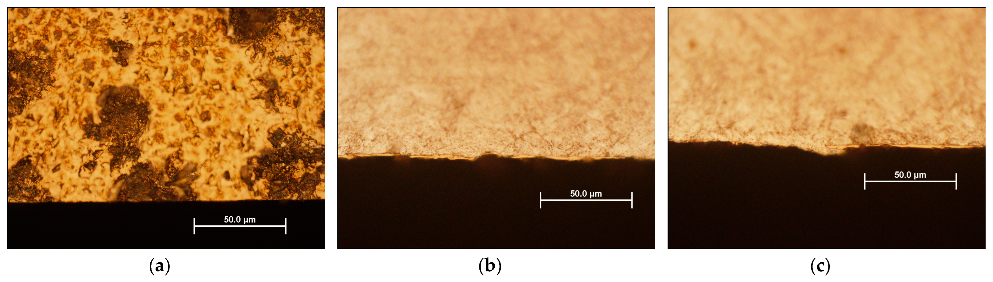
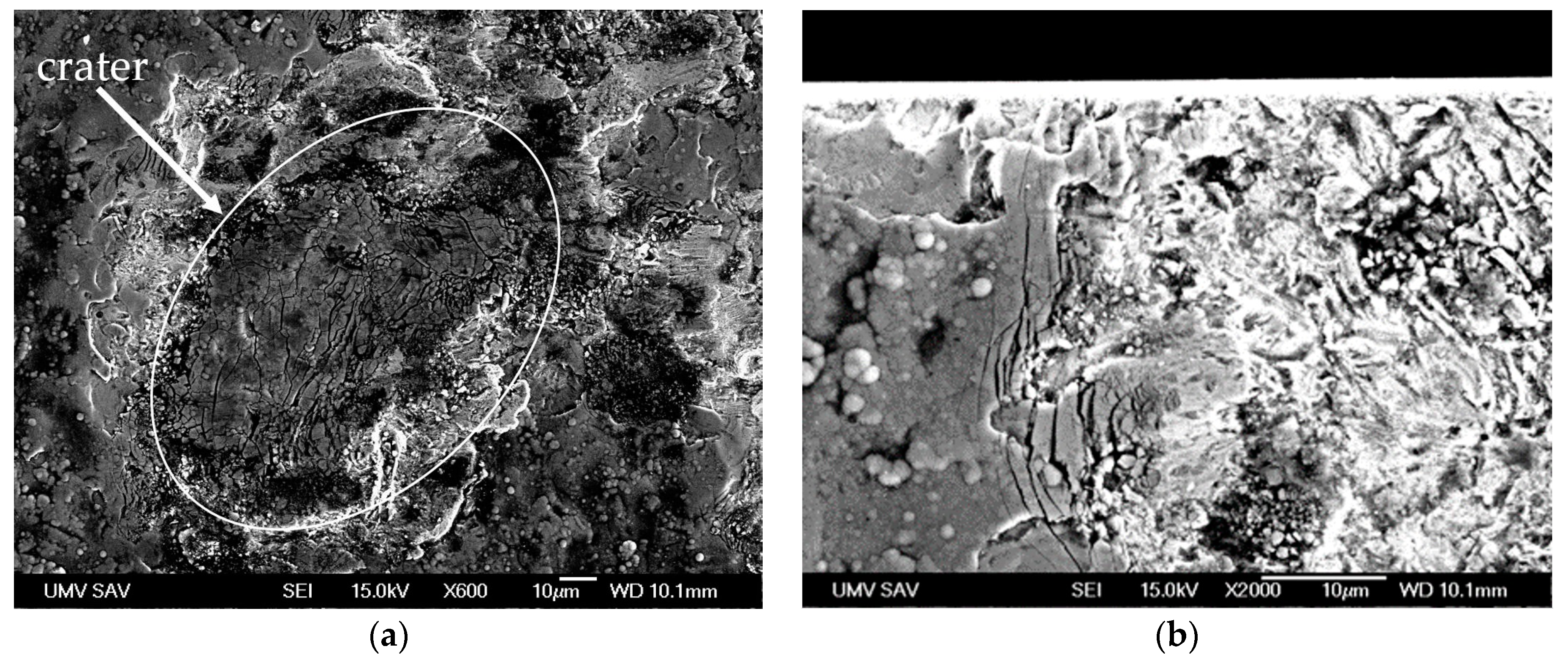
3.1. Optical Microscopy and SEM Analysis

Figure 3 shows the SEM image of the cross-sections of the TiN-coated insert (with a coating thickness of around 2 µm) and the results of the EDX determining the elemental composition of the TiN.
Optical and SEM analyses were performed to identify possible failures on the surface of the insert. The TiN-coated insert served as an example for the illustration of emerging failures on the surface. The examined insert was after 15,000 shots. Figure 4 shows the surface morphology and cross-sections of the specimen of the TiN-coated insert. The image of the surface morphology illustrated in Figure 4a shows the erosion of the coating presented by multiple craters, which were concentrated in a ring around the inner hole of the insert. Figure 4b shows the wear and degradation of the coating. There are areas of missing coating and indentation. Figure 4c illustrates that in addition to wear and uncoated areas, there is a visible rise of material above the coating. These failures have significant importance in terms of the surface quality of the produced casting (there is a low maximum tolerance limit of average surface roughness). The failure negatively impacts the insert’s lifetime.
Figure 5 shows the SEM images of the specimen with the TiN-coated insert. Figure 5a illustrates the details of the crater, whose center is formed by island-like formations of the coating. In Figure 5b, a more detailed coating failure is visible, which is accompanied by the gradual breaking off of small sharp parts of the coating. This cracking is probably caused by the cyclic thermomechanical effect of the HPDC process.
Figure 6 shows cross-sections of the specimen of the insert coated with TiN after shots. The first, Figure 6a, shows the thinned thickness of the coating, which is around 1.25 µm. Figure 6b shows local erosion of the surface under 0.8 μm in the form of a regular crater. Under the coating, local plastic deformation of the basic material is visible. It is probably caused by high temperatures and high stress. Cavities were visible in several places in the cross-section. Figure 6c shows local coating failure at the bottom, which is the basic metal of the mold insert. The failures and cracks (Figure 5b) can be a prerequisite for the formation of intermetallic layers of Fe–Al as was mentioned by several studies, but within our analysis, the intermetallic layers were not identified.

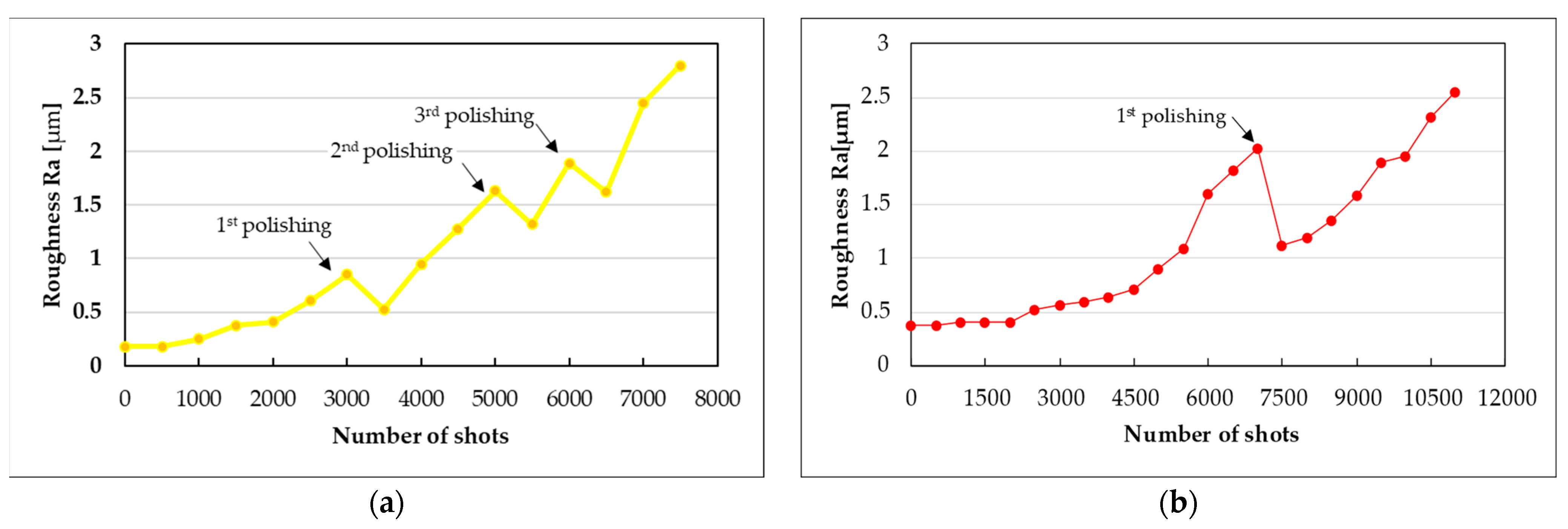
3.2. Hardness and Surface Roughness

Table 3 shows the values of parameters that were measured on the surface of the inserts before the initiation of the casting process. As can be seen in Table 3, the uncoated insert achieved the optimal value of hardness—48 HRC after the heat treatment, as it was mentioned as the value within the desired range according to [13] (p. 120) and [3] (p. 235). The roughness of the uncoated insert was the lowest, achieving Ra = 0.10 µm. PVD coatings increased the hardness of the inserts. The highest hardness of the PVD-coated inserts was measured for the TiAlN and the lowest for the TiN-coated surface. TiAlN and CrAlSiN have more complex crystal structures compared to TiN. The incorporation of aluminum and silicon causes lattice distortions, increasing hardness. The TiN-coated insert had the highest roughness of Ra = 0.46. The lowest roughness was measured for the surface with the deposited CrAlSiN coating with Ra = 0.34. The arc vapor deposition can introduce macroparticles or droplets, affecting the surface roughness. The smoother surface of CrAlSiN could be affected by the refining effect of silicon on the grain structure.
The following Figure 7 shows the measured Ra values of the casting surface after every 500 shots using the uncoated insert and inserts protected with CrAlSiN, TiAlN, and TiN. The wear of the inserts’ surface negatively affects the surface of the castings produced. It increases the roughness of the casting surface. As we take into account the customer requirement, of which the maximum allowed value of the produced casting’s surface is Ra = 2.5 µm, the possible inserts’ lifetime is limited. Castings with higher values of Ra cannot be delivered to the customer and are considered as a non-conformity, and inserts are decommissioned.
The uncoated insert during the examination was polished thrice, as the roughness value was rapidly increasing. The goal was to prolong the lifetime of the inserts used in the production, taking into account the maximum prescribed Ra value for castings. However, it had a minimal effect on lowering the roughness value and lifetime prolongation of the insert. The first polishing helped to slightly decrease the roughness—ΔRa 0.32. A similar effect of lowering of the roughness was also observed after the second and third polishing. The lifetime of the insert ended after 7000 shots as the Ra value reached the tolerance limit of Ra = 2.5 µm. If the production had been continued, non-conforming castings would have been produced.
In the case of the inserts protected by CrAlSiN and TiAlN coatings, the polishing was performed one time, when the value of Ra was approaching 2 µm. The TiN-coated insert was not polished. The roughness of the CrAlSiN-coated insert started to grow significantly after 4500 shots (linear growth). Polishing was performed after 7000 shots. The polishing brought a more significant decrease in roughness in comparison with the uncoated insert. However, it started to increase at the same pace, and after 3000 shots, the roughness achieved the value before polishing. The Ra value of the TiAlN-coated insert started to rise more significantly (linear) after 3500 shots. At 900 shots, as it significantly increased up to the value of Ra = 2, it was polished, and after 11,000 shots, the value reached that before polishing. This insert was used until 12,000 shots. The highest efficiency was achieved using the TiN-coated insert, where the increasing roughness of the produced castings was the lowest and compared to the inserts protected with the previously mentioned coatings, Ra = 2 was reached until 13,000 shots. Therefore, the polishing of this insert was not realized. It was possible to use this insert until 15,000 shots without polishing.
Figure 8 shows the increase of roughness (Ra) of the castings produced using the uncoated insert and PVD-coated inserts (TiN, TiAlN, and CrAlSiN). There is a significant difference between the uncoated insert and other PVD-protected inserts in terms of the insert lifetime. The deposition of PVD coatings prolonged the inserts’ lifetime. Despite the highest initial roughness of the TiN-coated insert, it was able to achieve the highest number of shots until the produced castings achieved the limited value of Ra without polishing. Although TiN has a lower oxidation temperature in comparison with the TiAlN and CrAlSiN coatings, and some studies concluded better wear and corrosion resistance of TiAlN than TiN, in our study, under the given process conditions (described in Material and Methods), the TiN coating achieved the longest lifetime. It is considered to be the best option for the organization in terms of effectiveness and efficiency.
The TiN-coated surface had the highest roughness, which could cause the capturing of lubricant (applied after shots) that protects the surface. This effect was confirmed in the case of textured PVD coatings in the study according to [33].

4. Conclusions

Based on our study, the main conclusions resulting from the investigations and analysis are as follows:
  • The optical and SEM analysis showed wear and the formation of craters at the bottom, of which the uncovered basic material of the insert is visible. The study of surface morphology revealed the presence of cracks probably caused by the cyclic thermomechanical effect. These failures can be prerequisites for the formation of intermetallic Fe–Al layers. They negatively affect the surface quality of castings, manifesting by increasing average roughness (Ra).
  • The PVD-coated inserts achieved a significantly longer lifetime than uncoated inserts concerning the requirements of casting surface roughness (Ra), while the TiN-coated insert performed the best in comparison with TiAlN- and CrAlSiN-coated inserts. The difference in lifetime using TiAlN- and CrAlSiN-coated inserts was only 10,000 shots, with an advantage for TiAlN.
  • The polishing performed to prolong the inserts’ lifetime had a minimal effect on the uncoated insert (prolongation of lifetime by 500 shots). It was also applied in the case of TiAlN- and CrAlSiN-coated inserts when they were approaching the critical value of Ra and the prolongation of lifetime ranged from 2000 to 3000 shots.

Author Contributions

Conceptualization, A.S.; methodology, A.S. and R.K.; formal analysis, I.P. and P.P.; investigation, R.K. and A.S.; resources, M.K.; writing—original draft preparation, A.S.; writing—review and editing, P.P. and A.P.; visualization, A.P. All authors have read and agreed to the published version of the manuscript.

Funding

This research received no external funding.

Institutional Review Board Statement

Not applicable.

Informed Consent Statement

Not applicable.

Data Availability Statement

Data are contained within the article.

Conflicts of Interest

The authors declare no conflicts of interest.

References

  1. Mayer, A.R.; de Oliveira, W.R.; Fals, H.D.C.; Lima, M.J.; Gonçalves, C.S.; Munoz, N.; Corso, J.L.; Pukasiewicz, A.G.M.; Mayer, A.R.; de Oliveira, W.R.; et al. Die soldering and corrosion failure of high temperature tool steel for high-pressure die casting Al alloy. Eng. Fail. Anal. 2024, 161, 108314. [Google Scholar] [CrossRef]
  2. Nunes, V.; Silva, F.J.; Andrade, M.F.; Alexandre, R.; Baptista, A.P. Increasing the lifespan of high-pressure die cast molds subjected to severe wear. Surf. Coat. Technol. 2017, 332, 319–331. [Google Scholar] [CrossRef]
  3. Terek, P.; Kovačević, L.; Miletić, A.; Panjan, P.; Baloš, S.; Škorić, B.; Kakaš, D. Effects of die core treatments and surface finishes on the sticking and galling tendency of Al–Si alloy casting during ejection. Wear 2016, 356–357, 122–134. [Google Scholar] [CrossRef]
  4. Markežič, R.; Naglič, I.; Mole, N.; Šturm, R. Experimental and numerical analysis of failures on a die insert for high pressure die casting. Eng. Fail. Anal. 2019, 95, 171–180. [Google Scholar] [CrossRef]
  5. Chen, Z.W.; Jahedi, M.Z. Die erosion and its effect on soldering formation in high pressure die casting of aluminium alloy. Mater. Des. 1999, 6, 303–309. [Google Scholar] [CrossRef]
  6. Kohlhepp, M.; Uggowitzer, P.J.; Hummel, M.; Höppel, H.W. Formation of Die Soldering and the Influence of Alloying Elements on the Intermetallic Interface. Materials 2021, 14, 1580. [Google Scholar] [CrossRef]
  7. Chen, Z.W. Formation and progression of die soldering during high pressure die casting. Mater. Sci. Eng. 2005, 397, 356–369. [Google Scholar] [CrossRef]
  8. Domkin, K.; Hattel, J.H.; Thorborg, J. Modeling of high temperature- and diffusion-controlled die soldering in aluminum high pressure die casting. J. Mater. Proc. Technol. 2008, 209, 4051–4061. [Google Scholar] [CrossRef]
  9. Salem, M.; Le Roux, S.; Dour, G.; Lamesle, P.; Choquet, K.; Rézaï-Aria, F. Effect of aluminizing and oxidation on the thermal fatigue damage of hot work tool steels for high pressure die casting applications. Int. J. Fatigue 2019, 119, 126–138. [Google Scholar] [CrossRef]
  10. Sütőová, A.; Grzinčič, M. Creation of Defects Catalogue for Nonconforming Product Identification in the Foundry Organization. Qual. Innov. Prosper. J. 2013, 17, 52–58. [Google Scholar] [CrossRef]
  11. Teplická, K. Comparison of Using Managerial Instruments in Industry Companies in Slovakia and the Czech Republic. TEM J. 2019, 8, 1191–1197. [Google Scholar] [CrossRef]
  12. Brezinová, J.; Viňáš, J.; Džupon, M.; Jakubeczyová, D.; Brezina, J.; Sailer, H.; Hašuľ, J.; Považan, M. Use of Duplex PVD Coatings to Increase the Life of Moulds and Cores for die Casting of Aluminium Alloys in the Automotive Industry. Acta Mech. Slovaca 2022, 26, 42–51. [Google Scholar] [CrossRef]
  13. Bhaskar, M.; Anand, G.; Nalluswamy, T.; Suresh, P. Die Life in Aluminium High-Pressure Die Casting Industries. J. Inst. Eng. India Ser. D 2022, 103, 117–123. [Google Scholar] [CrossRef]
  14. Gulizia, S.; Jahedi, M.Z.; Doyle, E.D. Performance evaluation of PVD coatings for high pressure die casting. Surf. Coat. Technol. 2001, 140, 200–205. [Google Scholar] [CrossRef]
  15. Rosso, M.; Ugues, D.; Torres, E.; Perucca, M.; Kapranos, P. Performance enhancements of die casting tools trough PVD nanocoatings. Int. J. Mater. Form. 2008, 1, 1259–1262. [Google Scholar] [CrossRef]
  16. Paiva, J.M.; Fox-Rabinovich, G.; Junior, E.L.; Stolf, P.; Ahmed, Y.S.; Martins, M.M.; Bork, C.; Veldhuis, S. Tribological and Wear Performance of Nanocomposite PVD Hard Coatings Deposited on Aluminum Die Casting Tool. Materials 2018, 11, 358. [Google Scholar] [CrossRef]
  17. Midson, S.P.; De Campos Neto, N.D.; May, W.; Korenyi-Both, A.L.; Kaufman, M.J. Laboratory Testing to Characterize the Use of PVD Coatings and Alternate Die Materials for Reducing Soldering and Erosion for Aluminum Die Casting Applications. Int. J. Metalcast. 2024, 18, 1–14. [Google Scholar] [CrossRef]
  18. Campos Neto, N.D.; Korenyi-Both, A.L.; Vian, C.; Midson, S.P.; Kaufman, M.J. The development of coating selection criteria to minimize die failure by soldering and erosion during aluminum high pressure die casting. J. Mater. Proc. Technol. 2023, 316, 117954. [Google Scholar] [CrossRef]
  19. Torres, E.; Ugues, D.; Brytan, Z.; Perucca, M. Development of multilayer coatings for forming dies and tools of aluminium alloy from liquid state. J. Phys. D Appl. Phys. 2009, 42, 105306. [Google Scholar] [CrossRef]
  20. Vetter, J.; Eriksson, A.O.; Reiter, A.; Derflinger, V.; Kalss, W. Quo Vadis: AlCr-Based Coatings in Industrial Applications. Coatings 2021, 11, 344. [Google Scholar] [CrossRef]
  21. Ugues, D.; Torres, E.; Perucca, M.; Albertinazzi, M.; Rosso, M. Hard coatings to prevent the washout phenomena in high pressure die casting tools. BHM Berg- Hüttenmännische Monatshefte 2006, 151, 109–112. [Google Scholar] [CrossRef]
  22. Gurada, C.; Mundotia, R.; Mhatre, R.; Kale, A.; Kothari, D. Thermal Fatigue Resistance Studies of Multilayer CrN and AlTiN Coatings Deposited on Plasma Nitrided H-13 Hot Work Steel. Lubricants 2023, 11, 19. [Google Scholar] [CrossRef]
  23. Khadem, M.; Penkov, O.V.; Yang, H.K.; Kim, D.E. Tribology of multilayer coatings for wear reduction: A review. Friction 2017, 5, 248–262. [Google Scholar] [CrossRef]
  24. Matei, A.A.; Turcu, R.N.; Pencea, I.; Herghelegiu, E.; Petrescu, M.I.; Niculescu, F. Comparative Characterization of the TiN and TiAlN Coatings Deposited on a New WC-Co Tool Using a CAE-PVD Technique. Crystals 2023, 13, 112. [Google Scholar] [CrossRef]
  25. Das, D.; Guha, S.; Ghadai, R.; Swain, B.P. A comparative analysis over different properties of TiN, TiAlN and TiAlSiN thin film coatings grown in nitrogen gas atmosphere. Mater. Chem. Phys. 2021, 258, 123866. [Google Scholar] [CrossRef]
  26. Obrosov, A.; Gulyaev, R.; Ratzke, M.; Volinsky, A.A.; Bolz, S.; Naveed, M.; Weiß, S. XPS and AFM Investigations of Ti-Al-N Coatings Fabricated Using DC Magnetron Sputtering at Various Nitrogen Flow Rates and Deposition Temperatures. Metals 2017, 7, 52. [Google Scholar] [CrossRef]
  27. Yoon, S.Y.; Lee, K.O.; Kang, S.S.; Kim, K.H. Comparison for mechanical properties between TiN and TiAlN coating layers by AIP technique. J. Mater. Proc. Technol. 2002, 130–131, 260–265. [Google Scholar] [CrossRef]
  28. Liew, W.Y.; Jie, J.L.; Yan, L.Y.; Dayou, J.; Sipaut, C.S.; Madlan, M.F. Frictional and Wear Behaviour of AlCrN, TiN, TiAlN Single-layer Coatings, and TiAlN/AlCrN, AlN/TiN Nano-multilayer Coatings in Dry Sliding. Proc. Eng. 2013, 68, 512–517. [Google Scholar] [CrossRef]
  29. Liu, Y.; Yu, S.; Shi, Q.; Ge, X.; Wang, W. Multilayer Coatings for Tribology: A Mini Review. Nanomaterials 2022, 12, 1388. [Google Scholar] [CrossRef]
  30. Wang, Q.; Zhou, F.; Wang, C.; Yuen, M.-F.; Wang, M.; Qian, T.; Matsumoto, M.; Yan, J. Comparison of tribological and electrochemical properties of TiN, CrN, TiAlN and a-C:H coatings in simulated body fluid. Mater. Chem. Phys. 2015, 158, 74–81. [Google Scholar] [CrossRef]
  31. Berger, C.; Scheerer, H.; Ellermeier, J. Modern materials for forming and cutting tools—Overview. Mater. Werkst. 2010, 41, 5–16. [Google Scholar] [CrossRef]
  32. Valleti, P.C.; Venu Gopal, A.; Joshi, S.V. CrAlSiN nanocomposite thin films for high-speed machining applications. Mater. Manuf. Process. 2018, 33, 371–377. [Google Scholar] [CrossRef]
  33. Brezinová, J.; Džupon, M.; Puchý, V.; Brezina, J.; Maruschak, P.; Guzanová, A.; Sobotová, L.; Badida, M. Research on the Tribological Properties of a New Generation of Multi-Layer Nanostructured PVD Coatings for Increasing the Technological Lifetime of Moulds. Metals 2024, 14, 131. [Google Scholar] [CrossRef]
  34. Tošenovský, F.; Tošenovský, J.; Blaštíková, M. Selected Problems in Statistical Modelling of Metallurgical Processes. In Proceedings of the 28th International Conference on Metallurgy and Materials, Brno, Czech Republic, 22–24 May 2019. [Google Scholar] [CrossRef]
  35. Ding, R.; Yang, H.; Li, S.; Hu, G.; Mo, J.; Chu, M.; Paddea, S.; Zhang, S.; Zhang, P.; Liu, Z.; et al. Failure analysis of H13 steel die for high pressure die casting Al alloy. Eng. Fail. Anal. 2021, 124, 105330. [Google Scholar] [CrossRef]
  36. Mitterer, C.; Holler, F.; Üstel, F.; Heim, F.D. Application of hard coatings in aluminium die casting—Soldering, erosion and thermal fatigue behaviour. Surf. Coat. Technol. 2000, 125, 233–239. [Google Scholar] [CrossRef]
  37. Wiedenegger, A.; Bruckwilder, J.; Deutsch, C. Ecological and Economic Benefits of Additive Manufacturing in High Pressure Die Casting. BHM Berg- Hüttenmännische Monatshefte 2021, 166, 237–242. [Google Scholar] [CrossRef]
  38. Kobčar, D.; Kosec, L.; Kosec, B.; Tušek, J. Thermo fatigue cracking of die casting dies. Ing. Fail. Anal. 2012, 20, 43–53. [Google Scholar] [CrossRef]
  39. ISO 26423; Fine Ceramics (Advanced Ceramics, Advanced Technical Ceramics)—Determination of Coating Thickness by Crater-Grinding Method. ISO: Geneva, Switzerland, 2009.
  40. IATF 16949:2015; Quality Management System. International Automotive Task Force: Torino, Italy, 2016.
  41. ASTM A956:2022; Standard Test Method for Leeb Hardness Testing of Steel Products. American Society for Testing and Materials: West Conshohocken, PA, USA, 2022.
  42. DIN EN 50156-1:2016; Electrical Equipment for Furnaces and Ancillary Equipment. VDE: Berlin, Germany, 2016.
  43. JSA-JIS B 0601; Geometrical Product Specifications (GPS}—Surface Texture: Profile Method—Terms, Definitions and Surface Texture Parameters. JSA: Tokyo, Japan, 2013.
  44. ISO 21920-2:2021; Geometrical Product Specifications (GPS)—Surface Texture: Profile—Part 2: Terms, Definitions and Surface Texture Parameters. ISO: Geneva, Switzerland, 2021.
Figure 1. Mold inserts: (a) uncoated; (b) coated with CrAlSiN; (c) coated with TiAlN; and (d) coated with TiN.
Coatings 14 01043 g001
Figure 2. Throttle body with the marked value of the bearing surface roughness specified by the customer (Ra = max. 2.5 μm).
Coatings 14 01043 g002
Figure 3. SEM image of cross-section of TiN-coated insert before use and results of EDX analysis.
Coatings 14 01043 g003
Figure 4. Optical microscopy images of the specimen of the insert coated with TiN after shots: (a) surface morphology of specimen; (b) cross-section of the specimen; and (c) cross-section of the specimen.
Coatings 14 01043 g004
Figure 5. SEM backscattered electron images of surface morphology of the insert’s specimen coated with TiN after shots: (a) crater and (b) surface failure.
Coatings 14 01043 g005
Figure 6. SEM of cross-sections of insert’s specimen coated with TiN after shots: (a) thinned coating; (b) local erosion; and (c) local coating failure.
Coatings 14 01043 g006
Figure 7. Average roughness values (Ra) of the bearing surfaces of castings after the shots using: (a) uncoated insert; (b) insert with CrAlSiN-coated film; (c) insert with TiAlN-coated film; and (d) insert with TiN-coated film.
Coatings 14 01043 g007aCoatings 14 01043 g007b
Figure 8. Average roughness values (Ra) of the bearing surfaces of castings using an uncoated insert and coated inserts with TiN, TiAlN, and CrAlSiN.
Coatings 14 01043 g008
Table 1. AISI H 11 (DIN × 38 CrMoV5-1) chemical composition (wt. %).
CSiMnCrMoVFe
0.380.900.405.201.300.45balance
Table 2. AlSi11Cu2(Fe) chemical composition (wt. %).
FeSiMnNiCrTiCuPbMgZnSnAl
max
1.1
10–
12
max
0.55
max
0.45
max
0.15
max
0.25
1.5–
2.5
max
0.25
max
0.3
max
1.7
max
0.15
balance
Table 3. Values of parameters of uncoated insert and inserts coated with CrAlSiN, TiAlN, and TiN.
Measured
Parameters
UncoatedCrAlSiN-
Coated
TiAlN-CoatedTiN-Coated
Hardness (HRC)
Mean48525350
SD0.40.91.10.6
Roughness (µm)
Ra0.100.340.390.46
Rz0.61.11.61.4
Disclaimer/Publisher’s Note: The statements, opinions and data contained in all publications are solely those of the individual author(s) and contributor(s) and not of MDPI and/or the editor(s). MDPI and/or the editor(s) disclaim responsibility for any injury to people or property resulting from any ideas, methods, instructions or products referred to in the content.

