


Abstract
Physical unclonable functions (PUFs) convert device-specific physical variations into responses for chip identity, key reconstruction, secure boot, and hardware roots of trust. This review examines the complete PUF chain from entropy generation and response digitization to stabilization, post-processing, deployment, security evaluation, and low-power implementation. Mature CMOS delay, SRAM, and DRAM PUFs are treated as engineering baselines, while representative emerging-memory PUFs provide comparison points for a MRAM-centered analysis. The main focus is placed on MRAM PUFs, including static MTJ variation, stochastic STT/SOT switching, response digitization and stabilization, reconfigurability, magnetic-specific attack surfaces, and system integration. The main contents include MRAM-PUF energy costs across device operation, raw-response generation, response stabilization, key reconstruction, and complete authentication. This cross-layer perspective distinguishes cell-level read/write energy from repeated sampling, reliable-bit-selection, ECC/KDF, controller, retry, and reconfiguration overheads. MRAM offers distinctive features including non-volatility, high endurance, and stochastic switching behavior. Their system-level energy benefits are treated as application-dependent and should be evaluated at the complete transaction level.
1. Introduction
Hardware security commonly relies on a verifiable device identity and a protected root key. Conventional embedded systems generate a root key and store or program it in EEPROM or Flash cells. The key can then support secure boot, encrypted communication, and firmware authentication. However, a long-lived stored secret may be exposed through invasive extraction, insecure provisioning, or manufacturing test, thereby increasing the risk of key cloning or disclosure [1].
A root of trust (RoT) refers broadly to a trusted foundation on which higher-level security functions depend and may be implemented through hardware, firmware, software, or a combination of these mechanisms. In this review, a hardware root of trust (HRoT) refers to a RoT whose security anchor is bound to hardware. Device identity or cryptographic key material is therefore generated, protected, or derived from hardware-resident characteristics and used to support authentication, key establishment, or secure boot. A PUF can provide such a hardware-bound identity or key-derivation primitive, but the PUF response alone does not constitute a complete HRoT. Practical realization also requires response stabilization, key derivation, protected interfaces, and system-level security controls.
A PUF can reduce reliance on long-term stored digital secrets by reconstructing a device-specific identity response or cryptographic key from in situ manufacturing variations [1,2]. The security value of the PUF depends not only on the unclonability of the physical response, but also on the enrollment type, helper data, debugging interfaces, and lifecycle updates [3,4].
However, in low-power electronics, the usefulness of PUF also depends on the energy required to obtain a stable and secure response. The physical entropy source may be inexpensive to sense, but enrollment, repeated sampling, error correction, helper-data generation, authentication protocols, and reconfiguration can dominate the total energy budget. Therefore, a PUF for edge devices, IoT nodes, or automotive controllers should be evaluated not only by uniqueness and reliability, but also by active energy, standby leakage, latency, energy per raw bit, and energy per reconstructed key [5,6].
The PUF concept originated from physical one-way functions and was later introduced into integrated circuits through silicon process variation [2,7]. Conventional silicon PUFs, including delay-, oscillator-, and memory-based designs, established the basic evaluation criteria of uniqueness, reliability, uniformity, and modeling resistance [4,8]. However, for low-power hardware roots of trust, these security metrics are insufficient unless they are reported together with read/write energy, standby power, latency, and post-processing overhead. Table 1 defines the search scope and screening criteria.
Table 1.
Literature search scope and evidence-screening criteria.
Figure 1 provides an overview of representative PUF technology families and the system-level considerations involved in their use as hardware roots of trust. The upper part groups representative PUFs according to their underlying implementation mechanisms, including traditional/canonical PUFs, CMOS delay/analog PUFs, SRAM/DRAM PUFs, MRAM PUFs, and other emerging non-volatile-memory PUFs. The lower part indicates a system-level design and evaluation workflow. Application requirements define the intended security function, while environmental and variability models specify the operating conditions. Circuit design converts physical variation into digital responses, security evaluation assesses robustness, and hardware/algorithm integration connects the PUF primitive to system-level security functions. These dimensions emphasize that a practical PUF is a system-level construction, jointly determined by device physics, circuit sensing, array addressing, post-processing, and cryptographic protocols [9,10,11].
Figure 1.
Representative PUF technology families and the system-level design and evaluation workflow for PUF-based hardware roots of trust.
Although previous studies have reviewed PUF architectures, applications, energy consumption, and post-processing overheads [5,6,8], these aspects are rarely organized around the specific device-to-system constraints of MRAM PUFs. The specific contribution of the review is an MRAM-centered cross-layer synthesis that places reported energy costs at clearly separated boundaries: device read/write operation, raw-response generation, response stabilization, key reconstruction, and complete authentication. This organization distinguishes experimentally reported energy costs from system-level advantages inferred primarily from device characteristics. It also identifies how sensing, repeated sampling, reliable-bit selection, ECC/KDF processing, reconfiguration, and protocol overhead can offset an apparent device-level advantage. In particular, magnetic-device parameters and MRAM-specific attack surfaces are connected to these energy and validation boundaries. Following the formation chain of a hardware root of trust, this review addresses five questions. First, how are physical responses generated in PUFs? Second, how should different technology routes be evaluated? Third, how can MRAM/STT-MRAM device features be converted into security advantages? Fourth, how should power and energy be reported from the cell level to the reconstructed-key level? Finally, how can a PUF support enrollment, authentication, key reconstruction, interface control, and lifecycle management in a real system?
2. Review Scope and Evidence Chain
The review is organized along an evidence chain of basic concepts, evaluation frameworks, technology routes, key devices, application deployment, and attack risks [6,12,13]. Figure 2 defines the validation framework used in this review to distinguish physical feasibility from progressively broader engineering and system-level validation. The stages range from theoretical modeling and single-device characterization to small-array experiments, chip-level demonstrations, and system/protocol validation. These stages differ in validation scope and in the types of claims that the available evidence can support. They do not represent increasing intrinsic PUF strength or imply a transition from a weak PUF to a strong PUF. The framework is therefore used to interpret reported results according to their demonstrated validation level rather than to rank PUF technologies by “strength.”
Figure 2.
Evidence-assessment framework used in this review to evaluate PUF research from physical feasibility to system-level deployment.
Accordingly, the reported results are interpreted together with their validation boundary. A favorable device-level metric, such as low switching energy or high uniqueness, is not treated as evidence of a low-energy or a secure hardware root of trust unless sensing, response stabilization, post-processing, environmental robustness, attack evaluation, and system-level overheads have also been considered. In Figure 2, therefore, the reported results are placed within their demonstrated validation boundaries instead of using the framework to rank PUF technologies.
In this review, mature PUFs, including CMOS, SRAM, and DRAM PUFs, are used as engineering baselines, while representative emerging-memory PUFs provide additional reference points for the MRAM-centered analysis. The principal focus is specific to MRAM PUFs, for which magnetic entropy generation and response digitization are connected with stabilization, security evaluation, energy cost, and hardware-root-of-trust deployment.
3. PUF Generation Mechanisms
Figure 3 shows conceptual PUF-supported workflows for secure authentication, key establishment, and IP protection. A PUF does not by itself constitute an authentication or key-exchange protocol. Instead, it provides hardware-bound secret material that must be incorporated into a freshness-protected and cryptographically authenticated protocol. In the key-establishment path, the locally reconstructed PUF-derived secret is used to authenticate fresh protocol messages exchanged between the communicating parties, which then derive and confirm a shared session key [14,15,16]. At the device level, the minimum abstraction of a PUF is usually written as , where C is the challenge, and R is the response.
Figure 3.
Conceptual PUF-supported workflows for secure authentication, key establishment, and IP protection.
In a real chip, however, the response is not the output of an ideal mathematical function. It is produced by physical parameters, environmental variables, noise, circuit decisions, and post-processing. A more engineering-oriented expression is Equation (1):
where i denotes the chip or device instance; E denotes temperature, voltage, external magnetic field, and electromagnetic noise; t denotes aging, wear, or the number of reconfiguration operations; ni denotes readout noise; and Q denotes sensing, comparison, quantization, and, where applicable, reliable-bit selection. Error correction, helper-data processing, and key derivation are treated as subsequent response-stabilization and key-reconstruction stages.
From the perspective of response generation, a PUF involves three core stages [12]. The first is the formation of a physical entropy source. In silicon CMOS chips, available variations include threshold voltage, channel length, metal linewidth, and parasitic capacitance. In SRAM memory, mismatch between cross-coupled inverters is commonly adopted. In DRAM memory, differences in capacitor leakage, retention time, and timing margins are used as PUF sources [13,17,18]. In RRAM, the position and the size of conductive filaments can be adopted as key parameters [19,20,21,22]. In PCM, the crystalline/amorphous distribution of phase-change materials is used [23]. In FeFETs, ferroelectric domains and threshold drift are key variations [24,25].
In the emerging MRAM, key parameters include MTJ device geometry, TMR, and STT writing parameters [26,27,28,29]. Recently, the design space has been extended to include ternary decisions and deep-learning-attack-resilient structures [30,31,32]. In SOT-MRAM, separated read/write paths, critical-pulse operation, and dynamic switching variation are the design space toward challenge-rich and dynamic PUF structures [33,34,35,36,37,38], unified PUF/TRNG architectures [36,39], and temperature-resilient reconfigurable schemes [40].
The second step is to convert continuous physical quantities into digital responses. A delay PUF obtains a 0 or 1 by comparing the arrival times of two paths [41]. A RO-PUF compares oscillation frequencies [42]. SRAM PUF reads the power-up preference of each cell [43]. DRAM PUF induces errors by reducing refresh, shortening timing, or extending retention [17]. RRAM/PCM/FeFET PUFs compare resistance or threshold values with reference cells or threshold windows [19,23,24]. MRAM PUFs can derive responses from resistance or differential comparisons [26,29,30], switching characteristics and near-critical-pulse outcomes [27,33], or repeated-sampling statistics in stochastic STT/SOT and p-bit operating regimes [27,38].
The third step is stabilization. Raw responses usually contain bias and noise. Therefore, they cannot be used directly as cryptographic keys. Engineering systems must select reliable bits, record a limited amount of helper data [44,45], recover a consistent response with error-correcting codes, and derive keys with a hash function or KDF [46,47]. A fuzzy extractor extracts nearly uniform keys from physical responses that are repeatable but not identical, while limiting leakage from public helper data [46].
PUF architectures can be described along several orthogonal dimensions, including challenge–response capacity, interface exposure, lifecycle behavior, response-generation regime, and functional mode. These dimensions are not mutually exclusive. For example, an MRAM PUF may be used as a weak PUF for local key reconstruction, protected by a controlled interface, and reconfigured during lifecycle renewal. From a low-power perspective, these modes introduce different energy costs. Strong PUFs may require repeated CRP evaluation, whereas controlled PUFs add interface and hashing overhead. Reconfigurable PUFs incur update and synchronization costs, while PUF/TRNG platforms require separate energy accounting for identity and randomness modes. Figure 4 summarizes representative mature PUF mechanisms used as baselines for the magnetic-memory discussion.
Figure 4.
Operating principles of arbiter, ring-oscillator, SRAM, and DRAM PUFs.
Silicon delay PUFs illustrate how microscopic process variations can be amplified into digital decisions. Fabrication variation first changes transistor threshold voltage, channel length, metal-interconnect width, and parasitic capacitance. When cascaded through challenge-controlled delay stages, small local variations are amplified into measurable path-delay differences, and the arbiter converts the delay comparison into a binary response. A PUF therefore converts nanoscale process fluctuations into digital decisions [2,3,4].
In SRAM PUFs, the power-up state of each cell is determined by the mismatch between the two cross-coupled inverters. Local variations in threshold voltage, carrier mobility, gate length, and mechanical stress make one storage node slightly stronger than the other. During power-up, positive feedback amplifies this imbalance and drives the cell toward either 0 or 1. Stable cells are useful for key material, whereas marginal cells require repeated sampling, reliable-bit selection, or ECC support [43,48,49,50].
DRAM PUFs exploit cell-to-cell variation in charge retention and timing margins. Differences in capacitor size, leakage paths, junction leakage, and sense-amplifier offsets cause some cells to lose stored charge earlier than others. When refresh intervals are extended, or timing margins are intentionally reduced, weak cells generate repeatable error patterns that can serve as device fingerprints [13,18,51]. Unlike non-volatile memory PUFs, however, DRAM PUFs often introduce latency and system-level energy overhead because retention waiting time, refresh control, and operating-system constraints become part of the response-generation process.
RRAM-, PCM-, and FeFET-based PUFs mainly exploit material- and switching-level randomness. Conductive filaments in RRAM can be formed by the migration of oxygen vacancies or metal ions, and their paths, thicknesses, and rupture locations cannot be precisely controlled [20]. In PCM, the shape and volume distribution of the amorphous region after programming are affected by thermal diffusion, cooling rate, and grain structure [23]. In FeFET, ferroelectric-domain switching exhibits threshold-voltage variation and cycle-to-cycle variation [24,25]. These mechanisms naturally produce discrete resistance or threshold distributions under identical programming conditions. To convert them into PUF responses, the system must set reference resistances or thresholds, divide analog distributions into binary or multilevel states, and use temperature compensation to avoid mistaking material drift for identity change.
The physical process of MRAM PUFs contains two classes of entropy sources. The first is static variation arising from MTJ area, MgO tunnel-barrier thickness, interfacial roughness, free-layer anisotropy, and demagnetization-field differences. These factors determine parallel/antiparallel resistance and TMR distribution. These static variations make MRAM suitable for stable weak-PUF and ternary-PUF implementations [26,30,32]. The second is dynamic switching variation arising from competition between thermal fluctuation and spin torque. When a write pulse is close to the critical condition, the switching of the cell becomes probabilistic. This behavior can be used for STT/SOT write randomness and p-bit-based challenge–response structures [27,38]. This phenomenon can also be extended to reconfigurable PUF and PUF/TRNG integration [39]. Static device-to-device variation is often used for stable identity and key-reconstruction PUFs, whereas near-critical stochastic switching can support either probabilistic PUF designs or TRNG operation. The distinction is not determined solely by the device mechanism. A PUF requires an enrollment procedure and a reproducible reconstructed output under defined conditions, whereas a TRNG intentionally produces fresh, non-repeatable outputs.
Raw PUF responses are generally noisy and therefore cannot normally be used directly as reproducible cryptographic keys. In key-oriented PUFs, helper-data algorithms (HDAs), commonly formulated through secure-sketch or fuzzy-extractor constructions [46], combine response stabilization with key derivation so that the same secret can be recovered from later noisy measurements. During enrollment, a reference response is used to generate secret key material together with helper data; during reconstruction, a new noisy response and the stored helper data are processed to recover the enrolled secret within the correction capability of the selected scheme.
Representative PUF helper-data constructions include fuzzy-commitment and code-offset fuzzy extractors, syndrome-based schemes, and reliability-aware or soft-decision approaches [44,47]. These constructions differ in the required number of raw PUF bits, helper-data size, decoding complexity, reliability, and implementation cost. Error-correction and helper-data design should also be evaluated from a security perspective because the amount of residual min-entropy after helper-data disclosure depends on both the statistical properties of the PUF response and the selected post-processing construction [52]. Accordingly, helper-data/ECC processing should be included when assessing key-reconstruction failure probability, latency, and energy per reconstructed key, particularly for MRAM PUFs.
Digitization methods strongly affect PUF quality. Fixed references may introduce global bias, while differential comparison can suppress common-mode drift [26]. Ternary decisions trade capacity for reliability [30], whereas probability-based sampling is more appropriate for stochastic STT/SOT or p-bit operating regimes [27,38]. In ternary/guard-band digitization, the two stable regions are mapped to 0 and 1, whereas measurements within an intermediate uncertainty region are labeled X and excluded or handled separately. Different decision methods are suitable for different applications. For example, key reconstruction prefers stable binary responses, strong PUFs require challenge-dependent mappings, and TRNGs require dynamic outputs with high entropy and low correlation.
4. Evaluation Metrics
PUF evaluation should not rely on a single indicator. A practical PUF must be distinguishable across different chips, stable on the same chip, statistically unbiased, resistant to learnable models, and secure after post-processing. Let L denote the response length in bits, and Ri(C) denote the L-bit response generated by chip i under challenge C. The response can be written as , where each term denotes an individual response bit.
4.1. Uniqueness
Uniqueness evaluates whether different chips generate different responses under the same challenge. It is usually measured by the average inter-chip Hamming distance. For N chips, the uniqueness is defined as
where N is the total number of independent PUF instances included in the inter-device comparison, L is the bit length of each PUF response, and denotes their Hamming distance. A uniqueness value close to 50% indicates that, on average, approximately half of the response bits differ between two independent PUF instances. If the value is much lower than 50%, it means responses from different chips are too similar, which weakens chip distinguishability. If the value is much higher than 50%, it may indicate abnormal complement bias or measurement artifacts rather than better security. Therefore, both the mean and variance of inter-chip Hamming distance should be reported.
4.2. Reliability
Reliability evaluates whether the same chip can reproduce the same response under repeated measurements and environmental changes. It is commonly measured by intra-chip Hamming distance or bit error rate. Let denote the enrolled reference response of chip i, and let denote its response in the m-th repeated measurement. The average intra-chip Hamming distance is defined as
where M is the number of repeated response evaluations performed on the same PUF instance under the specified test conditions, and L is the bit length of each PUF response. The reliability of chip can then be expressed as . Equivalently, the bit error rate is . The ideal intra-chip Hamming distance is 0%, and the ideal reliability is 100%.
In practice, reliability should be evaluated under different temperatures, supply voltages, aging conditions, repeated readout cycles, and external disturbances. For MRAM PUFs, external magnetic fields, write-pulse variation, read disturbance, and thermal effects should also be included.
4.3. Uniformity
Uniformity quantifies the balance between logic “0” and logic “1” within the response of an individual PUF instance. For chip , the uniformity is defined as
where L is the bit length of the response and denotes the j-th binary response bit generated by the i-th PUF instance. The device index i is fixed when evaluating the uniformity of a given PUF instance, whereas the summation over j covers all L-bit positions in that response. The ideal value is 50%, meaning that half of the response bits are 1 and half are 0. If the value deviates significantly from 50%, the response contains bias. A biased response reduces entropy and may make the PUF easier to predict. Therefore, uniformity should be reported for raw responses as well as for screened or post-processed responses.
4.4. Bit-Aliasing Rate
Bit-aliasing evaluates whether the same bit position tends to output the same value across different chips. For the -th response bit, the bit-aliasing rate is
The ideal value of is also 50%. If is close to 0%, most chips output 0 at this position. If is close to 100%, most chips output 1 at this position. Both cases indicate positional bias. Bit-aliasing is especially useful for identifying layout bias, reference-cell bias, sense-amplifier offset, array-edge effects, and systematic manufacturing gradients.
A useful overall indicator is the deviation of bit-aliasing from the ideal value:
A smaller indicates weaker positional bias.
4.5. Entropy and Randomness
Although uniqueness and uniformity describe statistical quality, they do not fully quantify the amount of extractable secret information. For key-oriented PUFs, entropy should be reported. For a single response bit with probabilities and , the min-entropy is
For an ideal unbiased bit, , and the min-entropy is 1 bit. If the response is biased, the min-entropy is lower than 1. For a full response , the min-entropy can be expressed as
In practical systems, entropy should be evaluated before and after reliable-bit selection. Over-screening can improve reliability but reduce entropy. Therefore, a security report should include raw-response entropy, screened-response entropy, helper-data leakage, and final key length.
4.6. Modeling Resistance and Protocol-Level Response Exposure
For strong PUFs, modeling resistance evaluates whether an adversary can learn the underlying challenge-to-response mapping when the assumed attacker model permits repeated CRP queries. This CRP availability should be understood as an attack-evaluation assumption rather than as a recommended authentication interface. In practical PUF-based systems, raw responses should normally remain inside the protected device boundary. Under the query-capable attacker model, suppose that an adversary obtains a training set and uses it to train a prediction model . The prediction accuracy on an unseen test set is
For bit-wise prediction, the accuracy can be written as
For bit-wise prediction of a balanced binary response, an ideal attack accuracy should be close to random guessing, namely 50%. A substantially higher prediction accuracy indicates exploitable structure in the underlying PUF mapping. Modeling-resistance evaluations should therefore report the number of CRPs available under the assumed attacker model, the training/test split, the evaluated model families, relevant hyperparameters, and prediction accuracy. Representative modeling attacks include linear or logistic models, evolutionary methods, and neural-network-based predictors [53,54].
Practical authentication should expose a different type of response. Rather than transmitting the raw PUF response R, a device can reconstruct device-bound secret material locally using response stabilization and helper-data processing and subsequently derive cryptographic key material through a KDF. The externally observable response is then a protocol-level authentication value, such as a MAC or another cryptographically protected token computed over a fresh nonce and protocol context. Alternatively, the reconstructed PUF-derived secret can be used to authenticate a key-establishment exchange. Representative recent PUF-based mutual-authentication and key-agreement protocols adopt such protected or session-oriented interfaces rather than relying on direct transmission or comparison of raw PUF responses [14,15,16].
Accordingly, modeling resistance and protocol-level exposure should be evaluated separately. The former characterizes the predictability of the underlying PUF mapping under an explicitly defined CRP-query attacker model, whereas the latter concerns what PUF-derived information is actually exposed through the deployed system interface.
4.7. Post-Processing Security
Because helper data are public auxiliary information, post-processing security should be evaluated in terms of information leakage, residual entropy, and reconstruction-failure probability.
For a linear error-correcting code with code length and dimension , the syndrome length is , which can therefore be used to estimate the upper bound of helper-data leakage. Therefore, the helper-data leakage is upper-bounded by
The remaining entropy after helper-data exposure can be estimated as
where is the entropy of the raw or selected response, and is the information leaked by helper data, masks, syndromes, or repeated enrollment. The failure rate of key reconstruction should also be reported:
where is the number of failed reconstruction attempts and is the total number of trials. A practical PUF-based key system should report the error-correction failure rate, helper-data size, KDF output length, enrollment-count limit, helper-data update rule, and whether debug interfaces can access raw responses or intermediate states.
4.8. MRAM-Specific Device Metrics
MRAM PUFs require additional device-level metrics because the response is affected by magnetic and spintronic parameters. The tunneling magnetoresistance ratio is commonly defined as
where and are the resistances of the parallel and antiparallel states, respectively. A larger TMR usually improves read margin, but it does not automatically guarantee better PUF quality.
The thermal stability factor of the free layer is
where is the energy barrier, is the Boltzmann constant, and is the temperature. For p-MTJs, is approximately related to the effective anisotropy energy and the free-layer volume. A larger Δ improves state retention but may reduce switching randomness. For switching-based STT-MRAM or SOT-MRAM PUF, the switching probability should be measured as
where is the number of successful switching events and is the number of applied write pulses.
Write energy can be approximated as
where , , and are the write voltage, write current, and pulse width, respectively.
For STT-MRAM and SOT-MRAM PUFs, evaluation should also include critical write current, pulse-width dependence, read-current margin, read disturbance, write endurance, local heating, supply-noise sensitivity, and external magnetic-field sensitivity. For reconfigurable MRAM PUF, the inter-response Hamming distance before and after reconfiguration should be close to 50%, indicating that the new response is statistically independent from the old one.
MRAM PUF evaluation should combine statistical metrics, security metrics, and magnetic-device metrics. In addition to uniqueness, reliability, uniformity, bit-aliasing, entropy, and modeling resistance, reports should include TMR, thermal stability, switching probability, pulse condition, read/write disturbance, magnetic-field sensitivity, and endurance.
4.9. Power-, Energy-, and Latency-Aware Evaluation Metrics
A PUF cannot be evaluated only by statistical security indicators [55]. For low-power electronic applications, power and energy should be reported at five nested accounting boundaries: device-level operation, raw-response generation, response stabilization, key reconstruction, and the complete authentication transaction. Device-level energy covers the underlying read, write, or switching operation. Raw-response generation additionally includes sensing and repeated measurements. Response stabilization includes reliable-bit selection, helper-data processing, and error correction. Key reconstruction further includes hashing/KDF and the controller overhead required to produce a usable cryptographic key, while the complete authentication transaction additionally includes protocol communication, verification, retries, and session establishment. The active energy of a basic PUF operation is expressed in Equation (18):
For rectangular read or write pulses, the same active-energy expression reduces to the pulse-energy approximation introduced in Equation (17). For key-oriented PUF applications, the more meaningful metric is the energy required to reconstruct a stable key rather than the energy of a single-cell-level operation. As shown in Equation (19), this energy includes raw-response generation, repeated sampling, reliable-bit selection, error correction, key derivation, controller overhead, and retry cost:
where denotes the energy for raw-response generation, denotes repeated-sampling energy, denotes reliable-bit-selection energy, denotes error-correction energy, denotes key-derivation energy, denotes controller and interface overhead, and denotes the energy caused by failed reconstruction.
The energy efficiency of a key-oriented PUF can be further described by usable-key bits per joule, as defined in Equation (20):
Therefore, low cell-level read or write energy does not necessarily imply low-power root-of-trust operation. Designs requiring extensive repeated sampling, large helper data, strong ECC, long latency, or frequent retries may still consume substantial system-level energy. This distinction is particularly important for MRAM PUFs because static MTJ-variation PUFs are mainly read-dominated, whereas switching-probability and reconfigurable MRAM PUFs are often pulse-energy-dominated [55,56,57,58].
5. Engineering Baselines and Emerging-Memory References for MRAM PUFs
CMOS delay PUFs are a classical starting point for strong-PUF research. In an arbiter PUF, two paths compete through multiple switchable delay stages, and the arbiter outputs which path arrives first. In RO-PUF, the frequencies of ring oscillators are compared [42]. Studies of modeling attacks have revealed the learnability of arbiter, XOR, polynomial, and related structures [53,54,59,60], and subsequent designs have improved nonlinearity and stability through combination, feedback, and reliability enhancement [41,61,62,63]. This approach offers small area, simple interfaces, and compatibility with FPGA and ASIC implementations. However, path delays are sensitive to temperature, voltage, and aging, while structural linearity makes it a natural target for machine-learning attacks.
SRAM, latch, flip-flop, and butterfly PUFs are bistable memory PUFs. At power-up, two cross-coupled inverters naturally prefer 0 or 1 because of mismatch in threshold voltage, transistor size, mobility, and local stress. These PUFs usually require little additional hardware and are therefore suitable for chip-unique IDs, key reconstruction, and secure boot [48,64,65]. However, unstable bits must be filtered out, power-up conditions may influence responses, and helper data may introduce leakage. In engineering deployments, SRAM PUFs are usually combined with secure-boot ROM, KDF, and anti-rollback counters rather than using raw SRAM start-up states directly as keys.
DRAM PUFs exploit retention decay and timing margins. When the refresh period is extended, charge leakage occurs in memory cells. When timing parameters such as tRCD or tRP are shortened, weak cells may generate repeatable read errors. These error patterns are correlated with manufacturing differences and can therefore be used as fingerprints [51]. DRAM PUFs offer large capacity and possible implementation on commodity memory, making them suitable for system-level authentication and memory-security research. Their challenges include temperature sensitivity, complex system scheduling, possible occupation of target regions by the operating system, and repeatability variations among vendors, batches, and controller policies.
NVMs introduce material randomness into PUFs. RRAM conductive filaments have paths that cannot be precisely controlled during forming, rupture, and reset [66]. PCM contains amorphous-volume distributions and resistance drift in phase-change regions [23]. FeFET ferroelectric-domain switching, threshold-voltage drift, and cycle-to-cycle variation can generate reconfigurable responses [24]. New memristor arrays have also demonstrated PUF/TRNG integration and concealable authentication capabilities [67,68]. These NVM PUFs show the advantages of high density, non-volatility, and compatibility with in-memory computing and array security. However, material randomness must be supported by reference cells, sense amplifiers, temperature compensation, and error correction since a high-entropy source does not automatically yield a reliable key.
For emerging NVM PUFs, the main concerns include reliability, power, read disturbance, reconfigurability, modeling resistance, package-level security, and application coupling. Energy behavior differs substantially among PUF routes. Delay and oscillator PUFs mainly consume dynamic switching and counter energy during challenge evaluation, and optimized CMOS PUF designs have reported fJ/bit-level response energy [55,56]. SRAM and latch PUFs reuse existing memory arrays and usually require little dedicated hardware, but cold-start control, repeated power-up sampling, helper-data generation, ECC, and KDF operations may dominate the full energy budget. DRAM PUFs may exploit commodity memory, yet long retention intervals, refresh manipulation, and operating-system constraints make latency and system-level energy important. RRAM, PCM, FeFET, and MRAM PUFs benefit from non-volatility and dense arrays, but programming, write-back, reconfiguration, and endurance costs must be considered together with standby power [57,69]. Because different PUF routes report power and energy at different abstraction levels, direct fJ/bit ranking can be misleading. Table 2 therefore summarizes representative energy-aware PUF implementations and clarifies the system boundary of each reported metric.
Table 2.
Representative energy-aware PUF implementations and comparison boundaries.
Cross-study energy comparison requires particular caution. The representative results summarized in Table 2 were obtained using different process nodes, device technologies, supply conditions, array sizes, peripheral circuits, and evaluation methods. Moreover, the reported energy boundary is not always identical: some studies report the energy of a raw PUF-cell operation or response bit, whereas others include sensing, repeated sampling, stabilization, or peripheral logic to different extents. Consequently, the absolute energy values in Table 2 are not used here to establish a strict ranking among PUF technologies. Instead, they provide an overview of the reported energy ranges and design characteristics in the literature. A rigorous energy comparison would require a common technology and operating point together with a consistently defined system boundary, preferably extending from raw-response generation to a usable reconstructed key or complete authentication transaction.
6. MRAM PUFs: From Magnetic Variation to Hardware Roots of Trust
MRAM provides a distinctive route for PUF construction because its security-relevant behavior originates from both device-to-device magnetic variation and stochastic magnetization switching. Compared with conventional CMOS delay PUFs or SRAM power-up PUFs, MRAM-based PUFs offer non-volatility, array compatibility, high endurance potential, and tunable write/read conditions. However, these device-level properties do not automatically imply stronger security or higher PUF quality. From a response-generation perspective, an MRAM PUF comprises four coupled elements. First, the magnetic device provides an entropy-bearing parameter, such as MTJ resistance, TMR, critical-switching current, or stochastic switching behavior. Second, the operating condition defines the read bias and the amplitude and duration of write pulses. Third, sensing and digitization convert resistance or switching behavior into binary or multilevel responses. Finally, response stabilization and output processing include reliable-cell selection, repeated sampling, helper-data-assisted error correction, and key derivation. The following subsections therefore distinguish static MTJ-variation PUFs and switching-based STT/SOT PUFs according to their physical entropy sources and response-generation mechanisms. Reconfiguration and PUF/TRNG co-integration are subsequently discussed as architectural and lifecycle functions that can be implemented using these underlying mechanisms.
Figure 5 shows the single-cell structures of STT-MRAM and SOT-MRAM and summarizes the relevant magnetic parameters. Four security modes are also shown in Figure 5, including weak PUF, reconfigurable PUF, strong PUF, and TRNG. Key parameters include Ku, P, Ms, tMgO, RP, RAP, and Ic. Practical implementations use memory arrays with peripheral circuits, sense amplifiers, and error-correction logic. STT-MRAM uses the MTJ path for both readout and spin-transfer-torque writing, whereas SOT-MRAM separates the write path through a spin–orbit layer from the MTJ read path. These structural differences affect response generation, read disturbance, and the relevant attack surface.
Figure 5.
STT-MRAM and SOT-MRAM read/write paths, magnetic parameters, and PUF/TRNG use modes.
The physical variation must then be converted into a digital PUF response. For static-variation PUFs, resistance, TMR-related quantities, or switching thresholds can be compared with a reference value or with another cell to assign a binary response. A guard-band or ternary scheme may additionally classify marginal measurements as an uncertain state (X), thereby improving reliability at the cost of usable-response density. For switching-based PUFs, the device is initialized, subjected to a defined near-critical write pulse, and read after the pulse. A single switching outcome may provide a response bit, whereas repeated trials can be used to estimate a cell-specific switching probability, which is subsequently mapped to a response according to the selected decision rule.
Practical MRAM PUF arrays additionally require sense amplifiers, reference or differential readout circuits, control logic, and, for key-oriented operation, response stabilization and post-processing. Thus, the PUF response is determined jointly by the magnetic device, excitation condition, sensing circuit, digitization rule, and stabilization mechanism rather than by the MTJ alone.
6.1. Magnetic-Memory Foundations and Security-Relevant Parameters
MRAM stores information in MTJ devices, where parallel and antiparallel magnetization states denote different resistances. An MTJ consists of a reference magnetic layer and a switchable free layer separated by a thin MgO tunnel barrier. The variations in MTJ geometry, barrier thickness, anisotropy, and switching dynamics can be used for potential PUF entropy [71,72].
From a PUF perspective, the relevant parameters are not limited to the binary P/AP state. Key response factors include MTJ geometry, barrier quality, magnetic anisotropy, thermal stability, TMR, critical-switching current, and local magnetic fields. Static variations in these parameters can create chip-unique resistance distributions, whereas dynamic thermal fluctuations can create probabilistic switching under near-critical pulses. Therefore, MRAM PUFs should not be described simply as “random magnetic devices.” A useful security claim must specify which physical parameter is used as the entropy source, whether the response is expected to be stable or stochastic, and how the magnetic response is converted into a reproducible digital output.
STT-MRAM and SOT-MRAM differ significantly at the circuit and attack-surface levels. In STT-MRAM, the write current passes through the MTJ stacks and directly exerts spin-transfer torque on the free layer. This structure is compact, but the write and read paths are not fully decoupled; therefore, write disturbance, read margin, and switching endurance must be considered together. In SOT-MRAM, the write current usually flows through an adjacent heavy-metal layer or spin–orbit material, while the MTJ stack is used mainly for readout. This separation can reduce read disturbance and allows more flexible control of switching probability, but it may introduce additional area cost, write-current requirements, and dependence on field-free or assisted switching mechanisms. At the PUF application level, these device-level distinctions determine not only response quality, but also the relevant attack model.
6.2. Static MTJ-Variation PUFs for Weak Identity and Key Reconstruction
The first type of MRAM PUFs uses static MTJ variation as the entropy source. Nominally identical MTJs still exhibit cell-to-cell variation in geometry, barrier quality, anisotropy, and local magnetic environment. These differences affect the parallel resistance, antiparallel resistance, TMR ratio, critical current, and read margin of each cell. During response extraction, the selected physical quantity is sensed electrically and then digitized according to a predefined decision rule. A fixed-reference scheme compares the measured value with a reference threshold, whereas a differential scheme compares two cells or branches and assigns the response according to their relative values. Reliability-aware schemes may introduce two thresholds and assign measurements within the intermediate guard region to an uncertain state (X), which is excluded or treated separately during enrollment. In this way, continuous device-to-device magnetic variation is transformed into a reproducible binary or ternary-PUF response.
The geometry-based MRAM PUF proposed by Das et al. is a representative example of this route [26]. It exploits MTJ geometry and TMR-related variation to generate chip-specific responses and demonstrates the feasibility of integrating magnetic PUF behavior with CMOS peripheral circuits. Subsequent studies extended this approach through array-level screening and reliability enhancement. Hu et al. demonstrated an STT-MRAM-based reliable weak PUF using MTJ variation, array screening, and post-processing, reporting near-ideal inter-chip Hamming distance and a low intra-chip error rate under the tested condition [28]. Ternary addressable MRAM PUFs assign marginal responses to a third state X, allowing unstable cells to be identified and excluded from ordinary binary key reconstruction or handled separately during enrollment. This reduces the contribution of unstable cells to the response BER, at the cost of lower usable-response density [30]. Recent magnetic-memory PUF studies have also reported improved reliability through device selection and response filtering [31].
The main advantage of static MTJ-variation PUFs is that they are naturally compatible with weak-PUF applications such as chip identification, key reconstruction, secure boot, and device binding. Since the response is derived from persistent device mismatch rather than repeated stochastic switching, the same enrolled response can in principle be reconstructed after power cycling. This makes static MRAM PUFs closer to SRAM PUFs in function, but with non-volatility and magnetic-device-specific design opportunities.
However, static MRAM PUFs also face limitations. If a global reference resistance is used, process gradients, sense-amplifier offsets, array-edge effects, or global temperature drift may bias many cells toward the same output value. Differential comparison can suppress part of this common-mode variation, but it reduces available entropy density and may introduce layout-dependent correlation. Ternary decisions can improve reliability, but they reduce the number of usable bits and require explicit reporting of the discarded-bit ratio. Therefore, static MRAM PUF evaluations should report not only uniqueness and uniformity, but also bit-aliasing, response correlation across neighboring cells, reliable-bit yield, reference-cell stability, helper-data leakage, and key-reconstruction failure rate.
From an energy perspective, static MTJ-variation PUFs are mainly read-dominated. Their low-power potential comes from non-volatility, resistance-based sensing, and the possibility of reconstructing a stable identity without repeated stochastic switching. However, the actual energy per reconstructed key depends on the sensing current, reference-cell calibration, sense-amplifier margin, reliable-bit yield, repeated reads, ECC, and KDF cost. Therefore, static MRAM PUFs should report not only read energy per cell, but also the number of raw cells required for one stable key, the discarded-bit ratio, helper-data size, reconstruction-failure rate, and energy per reconstructed key.
6.3. STT-MRAM Switching-Probability PUFs
The second type of MRAM PUFs uses stochastic spin-transfer-torque switching as the response-generation mechanism. In STT-MRAM, a current passing through the MTJ transfers spin angular momentum to the free layer. When the write pulse is sufficiently strong and long, switching becomes deterministic. When the pulse amplitude or pulse width is close to the critical-switching condition, thermal fluctuation and device-to-device variation make switching probabilistic. Different cells therefore exhibit different switching probabilities under the same nominal pulse condition. This cell-dependent probability can be used to generate responses through single-shot switching outcomes, repeated-sampling statistics, switching-time windows, or critical-current comparisons.
Marukame et al. specifically demonstrated that spin-transfer switching characteristics can serve as a PUF entropy source [27]. In contrast, Vatajelu et al. [29] and Hu et al. [28] provide complementary evidence for STT-MRAM array-level PUF implementation and reliable weak-PUF operation. Together, these studies show that STT-MRAM supports both static-variation-based and switching-dependent response-generation routes.
Figure 6 illustrates a response-generation chain in which fabrication-induced MTJ variations produce cell-specific critical-current and switching characteristics, while TMR primarily determines the readout margin for resolving the final parallel or antiparallel state. After a defined initialization and calibrated excitation, array selection, sensing, and reliable-cell screening convert the measured outcomes into digital response bits.
Figure 6.
From MTJ variability to digital response in a STT-MRAM PUF.
A key design issue in STT-MRAM switching PUFs is the choice of pulse condition. If the write pulse is too strong, most cells switch deterministically, and the response loses entropy. If the pulse is too weak, most cells remain unchanged, and the response becomes biased. A useful pulse condition should place a sufficient number of cells near the high-sensitivity region of the switching-probability curve while still allowing reliable enrollment and reconstruction. Because this probability depends on temperature, supply voltage, pulse shape, initial state, and magnetic parameters, pulse calibration should be reported together with PUF metrics. It is not enough to state that switching is stochastic; the distribution of switching probabilities and its drift under environmental variation must be measured.
STT-MRAM switching PUFs also introduce state-management problems. Unlike a pure readout-based PUF, a switching-based PUF may alter the magnetic state of the selected cell during response generation. The system must therefore define the initial state, write-before-read procedure, reset operation, maximum write count, and recovery flow after failed switching. If the same cell is repeatedly used, endurance and aging may change its switching probability over time. If different cells are used for different challenges, the address-selection mechanism becomes part of the security boundary and must be protected against probing or fault injection.
Figure 7 presents a cross-layer abstraction of an STT-MRAM PUF module, illustrating how device-level magnetic variation is progressively transformed into a stable response or reconstructed key. The entropy-bearing STT-MRAM array forms the physical core, where MTJ variation, critical-switching variation, and stochastic switching provide device-specific entropy. The surrounding layers represent access and excitation, sensing and digitization, response stabilization and key reconstruction, and the system security interface. A practical STT-MRAM PUF therefore depends on more than the MTJ array itself. Its operation also involves array selection, pulse excitation, sensing, response digitization, repeated sampling, reliable-cell selection, helper-data-assisted error correction, key derivation, and system integration.
Figure 7.
Cross-layer abstraction of an STT-MRAM PUF module and the associated energy-accounting and security/validation boundaries.
The two side axes in Figure 7 further distinguish the expansion of the energy-accounting and security-validation boundaries across these layers. On the energy side, the accounting boundary extends from device-level read/write or switching operations to raw-response generation, response stabilization, key reconstruction, and ultimately the complete system transaction. On the security side, the relevant validation scope similarly expands from device variation, aging, and disturbance to pulse or access manipulation, sensing bias and read disturbance, helper-data leakage and reconstruction failure, and finally side-channel and protocol-level exposure. The two boundaries therefore highlight that favorable device-level energy or entropy characteristics alone are insufficient to establish a low-energy and secure hardware root of trust.
Accordingly, STT-MRAM PUFs should be evaluated as memory-array security modules rather than as isolated stochastic devices. Evaluation should jointly report array-level PUF metrics, pulse-dependent switching characteristics, and system-level attack surfaces. In particular, write-current amplitude, switching time, address activity, and power traces may introduce side-channel leakage, while control and sensing interfaces may enlarge the fault-injection and manipulation surface. Device-level and protocol-level validation should therefore be considered together. The repeated sampling and near-critical excitation required by switching-based PUFs make their response-generation energy particularly sensitive to the accounting boundary.
6.4. SOT-MRAM and p-Bit Dynamic Challenge–Response Structures
A further response-generation route uses SOT-MRAM or spintronic p-bit devices to construct challenge-dependent PUFs. In SOT-MRAM, spin–orbit torque is generated by a charge current in a heavy-metal or spin–orbit layer and acts on the free layer of the MTJ. Separated read/write paths make SOT-MRAM attractive for reduced read disturbance and tunable probabilistic switching in dynamic or challenge-rich PUFs [33].
Finocchio et al. proposed a spin–orbit-torque-based PUF framework using SOT critical switching and thermal fluctuation [33]. Lee et al. demonstrated spintronic PUFs based on field-free SOT switching, showing that field-free switching behavior can be used for PUF construction [34]. Divyanshu et al. explored GSHE-driven SOT-assisted p-MTJ structures for hardware security applications [35]. More recent studies have extended SOT-MRAM toward dynamic entropy sources and strong-PUF designs, including SOT p-bit-based strong PUFs and experimental spintronic-memory PUF chips [38].
From a security perspective, SOT-MRAM is useful because its switching behavior can be controlled. By tuning pulse amplitude, pulse width, initial state, and device structure, the switching behavior can be placed in a probabilistic regime. If the challenge controls address selection, pulse parameters, sampling time, or response-composition rules, the PUF can provide a larger CRP space than a simple weak PUF. However, dynamic entropy alone does not guarantee modeling resistance. A strong or challenge-rich SOT-MRAM PUF must report the number of exposed CRPs, training/test partition, attack models, hyperparameters, random seeds, and prediction accuracy. Claims such as “machine-learning resistant” or “deep-learning immune” should be restricted to the evaluated attacker settings and should not be stated as absolute security guarantees.
SOT-MRAM PUFs also require a clear explanation of the switching mechanism. Some SOT devices require an external magnetic field for deterministic switching, while others use exchange bias, structural asymmetry, tilted anisotropy, or other field-free mechanisms. If an external or assist field is required, the practicality and attack surface of the PUF change substantially. When field-free SOT operation is claimed, the design should explain how field-free operation is achieved and whether the mechanism remains stable across chips, temperature, voltage, and aging. Since external magnetic fields can manipulate free-layer dynamics and switching probability, magnetic-field injection should be considered both an environmental stress and an active fault attack.
When p-bit devices are used, the response should be interpreted carefully. A p-bit is not a stable memory cell in the traditional PUF sense; it produces a controllable probabilistic output. This is useful for dynamic challenge–response structures and possibly for probabilistic computing or stochastic security primitives, but it should not be confused with a stable weak-PUF response. If a p-bit-based design is used for authentication, the protocol must define how many samples are collected, how probability is estimated, how noisy responses are accepted or rejected, and how replay or statistical modeling is prevented. If it is used as a TRNG, it must satisfy random-number-generation requirements rather than PUF reproducibility requirements.
For SOT-MRAM and reconfigurable MRAM PUFs, the low-power advantage should be discussed together with reconfiguration energy and lifecycle cost. SOT devices can benefit from separated read/write paths, fast switching, and low standby power, but reconfiguration may require additional write pulses, verifier synchronization, helper-data renewal, and rollback protection. Therefore, reconfigurable MRAM PUFs should report both normal authentication energy and reconfiguration energy, rather than only reporting the energy of one response-generation operation.
6.5. Reconfigurable MRAM PUFs and PUF/TRNG Co-Integration
Reconfiguration and PUF/TRNG co-integration are architectural directions that exploit the writability and non-volatility of magnetic memories. In a reconfigurable PUF, the physical response or the challenge–response mapping can be refreshed after suspected leakage, ownership transfer, repair, lifecycle update, or re-enrollment. Magnetic memories are attractive for this purpose because their states can be rewritten and retained without standby power. SOT-MRAM cache-based reconfigurable PUF systems and dynamically transformable magnetic PUF structures have been proposed to exploit these features [36]. Temperature-resilient and pulse-modulated spintronic PUFs further show that reconfiguration can be combined with environmental compensation and programmable operating conditions [40]. Reconfiguration must be authenticated, rollback-safe, and auditable. After reconfiguration, the system should report pre/post-response independence, helper-data renewal, reconstruction-failure rate, and server synchronization.
PUF/TRNG co-integration is useful only when the two operating modes are clearly separated. STT-MRAM and SOT-MRAM devices can generate stable identity responses under one operating condition and stochastic random outputs under another operating condition. Unified SOT-MTJ crossbar designs and other spintronic PUF/TRNG architectures have been proposed to use the same array platform for both functions [39]. Nevertheless, a PUF and a TRNG have opposite reproducibility requirements. A PUF response must be repeatable after enrollment, while a TRNG output must be non-repeatable and continuously refreshed. Therefore, a unified design should not claim that the same cell under the same operating condition simultaneously provides stable identity and true randomness.
6.6. Power and Energy Implications for MRAM PUF Design
The low-power relevance of MRAM PUFs comes from non-volatile retention, dense memory-array organization, and the possibility of reusing memory periphery for security functions. These device-level features, however, do not by themselves establish lower complete-transaction energy than SRAM PUFs. This distinction is particularly important for intermittently powered systems, because SRAM PUF circuitry can be power-gated between authentication events and reconstruct its device-specific response after power-up. Among the studies considered in this review, we did not identify a directly matched comparison of complete authentication-transaction energy between MRAM and SRAM PUFs. Such a comparison would require the same key length, reliability target, ECC/KDF configuration, retry policy, operating conditions, and energy-accounting boundary. MRAM non-volatility should therefore be regarded as an application- and duty-cycle-dependent potential benefit rather than as evidence of transaction-level energy superiority.
For static MTJ-variation PUFs, the transaction energy may include cell sensing, reference comparison, selected-bit extraction, and ECC/KDF logic. Their main low-power advantage is that enrolled states or device mismatches can be retained without refresh, which is valuable for intermittent or frequently sleeping systems. However, if the design must read a large array to obtain a small number of highly reliable bits, the energy per final key can become much larger than the energy per raw bit.
For switching-based STT-MRAM and SOT-MRAM PUFs, the dominant cost is often the write or challenge pulse. The approximate pulse energy in Equation (17) should be multiplied by the number of reset, challenge, verification, and resampling pulses required for one usable response. Near-critical pulses are attractive because they expose switching-probability variation, but they can also increase repeated sampling and latency. Stronger pulses may reduce error but collapse entropy and increase stress. As a result, the optimal operating point is not simply the lowest-energy pulse or the most random pulse, but the point that minimizes energy per stable and secure key under specified reliability and attack assumptions.
Reconfigurable MRAM PUFs require additional power/energy reporting because reconfiguration is a lifecycle operation rather than a simple read. The energy for erasing or refreshing a response, regenerating helper data, updating a verifier database, and verifying the new response should be included. If reconfiguration is rare, this cost may be amortized over the device lifetime. If it is used frequently for anti-cloning, session refresh, or post-compromise recovery, the reconfiguration energy and endurance cost become part of the regular security budget. For unified PUF/TRNG platforms, PUF mode should be optimized for reproducible low-error reconstruction, whereas TRNG mode should be optimized for fresh entropy per joule; mixing the two metrics can lead to misleading claims.
6.7. Attack Surfaces and Validation Requirements for MRAM PUFs
MRAM PUFs introduce attack surfaces that differ from those of SRAM or delay PUFs. MRAM PUFs inherit general PUF attack surfaces while additionally facing magnetic-field, pulse-control, and write-disturbance risks. External magnetic-field sensitivity deserves special attention. For magnetic PUFs, an external field is not merely an environmental disturbance; it may directly modify the energy landscape of the free layer, shift the switching-probability curve, bias the P/AP state, or induce faults during enrollment and authentication. A complete evaluation should specify field direction, field strength, exposure duration, AC/DC field condition, distance from the chip package, and whether the test is performed at wafer level, die level, or package level. If magnetic shielding, field sensors, anomaly detection, or lockout policies are used, they should be described as part of the security architecture rather than as optional implementation details.
The maturity of an MRAM PUF should be judged by evidence level. For MRAM PUFs, validation should additionally cover magnetic-field exposure, pulse-condition drift, read/write disturbance, endurance, reconfiguration synchronization, and helper-data renewal. These tests should be reported together with standard PUF metrics so that magnetic randomness can be linked to deployable security. Table 3 summarizes the energy-relevant validation boundaries for representative MRAM PUF routes from device operation to system-level deployment.
Table 3.
Energy-relevant validation boundaries for representative MRAM PUF routes.
7. Application Scenarios: How PUFs Become System Capabilities
PUF applications should be treated as lifecycle processes rather than isolated readout operations. A physical response becomes useful only when enrollment, deployment, authentication, update, failure handling, and retirement are connected through protected helper data, server records, counters, and access-control policies. Only under the closed-loop workflow can a PUF serve as a hardware-bound primitive within a practical hardware root of trust.
7.1. General Workflow: Enrollment, Authentication, and Key Reconstruction
From a system implementation perspective, PUF applications should first distinguish identity responses from key responses. An identity response may be stored by the server as a fingerprint digest to verify that a device matches the chip registered during enrollment. A key response should be locally stabilized through error correction and a KDF to derive keys for AES/SM4/HMAC, or to protect long-term private keys used in ECDH-based sessions.
A complete enrollment workflow should include environmental checks, repeated sampling, reliable-bit screening, helper-data generation, and secure server-side storage of digests, versions, and policies rather than plaintext responses.
Authentication should avoid directly transmitting raw responses. The verifier sends a fresh nonce together with the relevant protocol context or challenge identifier. The device evaluates the PUF locally, reconstructs the enrolled device-bound secret using the corresponding helper-data/ECC mechanism, derives protocol-specific authentication key material through a KDF, and returns a MAC or other cryptographically protected token over the fresh transcript. The raw PUF response remains within the device security boundary [14,16].
Reconstruction failures should trigger a bounded recovery policy, which may include resampling under qualified operating conditions, redundant response regions, or controlled re-enrollment. The retry limit and recovery sequence should be defined by the target reliability and threat model.
7.2. Typical Scenarios: Authentication, Boot, IP Protection, and Supply Chain
Device authentication, secure boot, IP protection, and supply-chain anti-counterfeiting are the most common system applications of PUFs. Device authentication emphasizes local secret reconstruction, freshness protection, cryptographically protected responses, and controlled interface access. Secure boot emphasizes local key reconstruction, firmware verification, helper-data protection, and failure recovery. IP protection for FPGA/SoC platforms emphasizes the binding of bitstreams or model parameters to a specific chip. Supply-chain anti-counterfeiting emphasizes trusted enrollment, batch databases, maintenance records, and retirement revocation. In these scenarios, PUFs provide physically unclonable evidence, but they still need to work with certificates, serial numbers, package tamper resistance, production records, and server databases.
For edge IoT, automotive, and industrial-control applications, PUF designs further shift toward low power, wide temperature range, long-term aging, and maintainability. Low-cost sensors may prioritize SRAM PUF because it reuses existing memory and has minimal additional area. Edge controllers that require non-volatility, frequent wake-up, and fast recovery may evaluate MRAM PUFs, especially when standby power, secure-boot latency, and energy per reconstructed key are critical. Automotive and industrial systems may prefer MRAM or highly reliable SRAM PUFs only if the design has been validated across voltage, temperature, aging, magnetic-field exposure, and power-management modes.
7.3. Application Boundaries for MRAM
For MRAM PUFs, the application advantage comes from where the magnetic array can be placed and how its operating modes can be controlled. If the PUF entropy source resides in an on-chip MRAM array, the root key can be reconstructed within the security boundary, reducing bus exposure. If the same platform additionally provides a separately controlled TRNG mode, that mode can supply nonces, masks, and session salts. For RISC-V security controllers, edge-AI accelerators, or automotive-grade MCUs, an illustrative integration pattern is to invoke the magnetic PUF after ROM boot to reconstruct a root key, decrypt secure configurations, and then enable the TRNG, access control, and debug lock.
A reconfigurable PUF can be used for key rotation, but reconfiguration must be implemented as a high-privilege, rollback-safe, and auditable process. The device should authenticate with its old PUF identity, then trigger reconfiguration within a secure session. It should locally verify the quality of the new response and generate new helper data. The new digest should be stored by the server, and the old version should be marked as invalid. The device should delete old helper data and update the anti-rollback counter. If power is lost during reconfiguration, the system must either restore the old state or complete confirmation of the new state. It must not enter a partially updated state that cannot be authenticated.
Application-oriented PUF selection cannot rely on a single metric such as uniqueness or reliability. As shown in Table 4, different scenarios require different PUF routes, security mechanisms, and power/energy priorities. No single PUF route is suitable for every scenario; each route should state its applicable problems, required security support mechanisms, and unsuitable boundaries.
Table 4.
Application scenarios, preferred PUF routes, and power/energy priorities.
Security boundaries should also cover test and production processes. A PUF chip may need to output large amounts of data during wafer testing to screen yield, but if these test data are stored for a long time or directly linked to chip serial numbers, they may become attack entry points. A safer practice is to output only quality metrics during testing rather than complete raw responses. If response enrollment is necessary, it should be performed in a controlled security environment and immediately bound to the access policy. After packaging, production-test interfaces should switch from observable modes to modes that cannot read raw responses, leaving only the minimal functions required for authentication, health checks, and re-enrollment.
Side-channel protection must be handled at both the circuit and protocol levels. The circuit level can use constant-time readout, balanced reference paths, shielding, randomized readout order, on-chip voltage regulation, and noise injection to reduce correlation between responses and power/EM signals. The protocol level can avoid repeated use of the same raw response and use nonces, counters, and KDFs to convert one-time PUF bits into session material. For magnetic PUFs, the amplitude, width, and edge shape of read currents and write pulses may all become observable features, so evaluation should measure power consumption, electromagnetic radiation, and error rates together.
Fault-injection protection should enforce the rule that secrets are never output under abnormal environmental conditions. If temperature, voltage, or magnetic field exceeds the enrollment range, the device should not continue to use the PUF-derived key. It should enter secure lockout, degraded authentication, or server-assisted recovery. Attackers may exploit boundary conditions to induce additional PUF response errors and infer internal states from helper data or error messages. Error information should therefore be intentionally vague and should not tell the attacker which bit failed, which error-correction stage failed, or how close the value was to the threshold.
For reconfigurable PUFs, reconfiguration abuse must also be prevented. If an attacker can repeatedly trigger reconfiguration, they may compare helper data or response digests across multiple rounds to find correlations, or cause the device and server to desynchronize. Repeated or unauthorized reconfiguration should be treated as an active attack and blocked through authenticated commands and monotonic version control. Old helper data should be unrecoverable after reconfiguration, old response digests should be marked invalid, and debug logs should not store intermediate data sufficient to infer relationships between old and new responses.
Security evaluation should be linked to the attacker capabilities summarized in Table 5. In particular, MRAM PUFs should be tested not only under normal readout, but also under abnormal temperature, voltage, magnetic-field exposure, pulse-width settings, debug access, and repeated-reconfiguration conditions.
Table 5.
Attacker capabilities, attack targets, and recommended countermeasures.
7.4. Barriers to Large-Scale Deployment of MRAM PUFs
Despite their favorable device-level characteristics, MRAM PUFs have not yet achieved deployment at a scale comparable with more mature silicon-based PUF solutions. This gap is not caused by a single limitation, but by the difficulty of preserving PUF-level entropy, reliability, energy efficiency, and security simultaneously when moving from individual devices or small arrays to manufacturable systems.
A first barrier arises from the tension between manufacturing optimization and entropy extraction. Conventional memory fabrication seeks narrow device distributions, high yield, large read margins, and predictable switching behavior, whereas a PUF deliberately exploits device-to-device variation or near-critical stochastic behavior. Excessive process variation may improve distinguishability but can also increase unstable cells, sensing errors, array gradients, and yield loss. Conversely, aggressive process control and circuit compensation may suppress the very variation used as the entropy source. Differential sensing, ternary decisions, reference-cell calibration, and reliable-bit selection can mitigate these problems, but they reduce usable-response density and introduce additional circuitry and enrollment complexity. Consequently, high reliability demonstrated for a selected response subset does not necessarily imply high usable-key yield across a large manufactured population.
A second barrier is uncertainty over whether device-level energy benefits survive complete system operation. As discussed in Section 6.6, the available literature does not yet provide a matched MRAM PUF versus SRAM PUF comparison under common reliability targets and energy-accounting boundaries. Device-level read or switching energy therefore cannot by itself establish a deployment-level energy advantage.
A third barrier is the present evidence gap between prototype feasibility and product qualification. Many MRAM PUF studies demonstrate device-, simulation-, array-, or chip-level feasibility, whereas large-scale deployment requires reproducible results across sufficiently large numbers of chips and fabrication batches, together with voltage, temperature, aging, magnetic-field, read/write-disturbance, endurance, and long-term retention tests. Security qualification also requires explicit evaluation of helper-data leakage, machine-learning attacks where applicable, side-channel leakage, fault injection, abnormal magnetic-field conditions, debug interfaces, and lifecycle operations such as re-enrollment and reconfiguration. These evaluations are not yet reported with sufficiently uniform system boundaries to allow direct comparison across MRAM PUF implementations.
Finally, MRAM PUFs must provide a system-level advantage over established alternatives rather than merely outperform them on an isolated device metric. SRAM PUFs, for example, can reuse memory that is already available in many systems and therefore impose little additional device integration cost. MRAM PUFs become particularly compelling when embedded MRAM is already available and when non-volatility, rapid wake-up, in-memory key reconstruction, low standby power, or reconfigurability provides an application-specific benefit. Large-scale adoption therefore depends not only on improving intrinsic PUF metrics, but also on demonstrating reproducible manufacturing yield, bounded reconstruction-failure probability, competitive energy per usable key, secure lifecycle management, and a clear integration advantage at the complete hardware-root-of-trust level.
8. Future Research Directions of MRAM PUFs
Figure 8 maps the design space of MRAM PUFs and highlights the trade-offs among stability, challenge space, reconfigurability, reliability, and system integration. The deployment barriers discussed above indicate that the principal challenge is no longer simply demonstrating magnetic randomness or favorable device-level PUF metrics, but establishing that these advantages survive manufacturing variation, system-level overhead, environmental stress, security evaluation, and lifecycle operation. Future research should move from isolated device demonstrations toward reproducible, attack-aware, and application-oriented hardware-root-of-trust validation. Five directions are particularly important.
Figure 8.
Design space of MRAM PUF.
First, standardized and reproducible benchmarking should be established. Future benchmarks should specify chip count, batch variation, environmental corners, magnetic-field exposure, disturbance tests, helper-data leakage, reconstruction-failure rate, standby power, active energy, latency, and energy per usable key. In addition to conventional metrics such as uniqueness, reliability, and uniformity, MRAM PUF studies should report TMR distribution, thermal stability, switching-probability curves, read/write disturbance, pulse condition, and endurance cost.
Second, power and energy should become first-class metrics rather than secondary implementation details. Reports should distinguish cell-level energy, peripheral energy, ECC/KDF energy, authentication-transaction energy, and reconfiguration energy. For key-oriented designs, energy per reconstructed key and usable-key bits per joule are more informative than energy per raw bit alone. For MRAM PUFs, standby-power reduction should be weighed against write-pulse cost, repeated sampling, and magnetic-disturbance protection.
Thirdly, attack-aware evaluation should become routine, with explicit attacker capabilities, reproducible test conditions, and disclosed modeling and side-channel evaluation settings. For strong or challenge-rich PUFs, the number of exposed CRPs, training/test partition, attack model, hyperparameters, random seeds, and prediction accuracy should be disclosed. For magnetic PUFs, additional attack surfaces should be considered, including external magnetic-field manipulation, pulse-width tuning, write-current disturbance, temperature acceleration, voltage noise, and repeated reconfiguration. A claim of modeling resistance or side-channel robustness is credible only when the attacker capability, measurement condition, and evaluation method are clearly stated and reproducible.
Fourthly, PUF/TRNG/in-memory-security integration should be developed with clearly defined isolation boundaries. For such integration, the significance of MRAM, STT-MRAM, and SOT-MRAM should be understood at the system level. Non-volatility is only one device feature; the more important issue is whether the same array platform can safely separate stable PUF responses, stochastic TRNG outputs, dynamic-key operations, and ordinary memory functions through controlled pulse conditions, access permissions, and read/write paths. Future designs should distinguish stable PUF cells, stochastic TRNG cells, ordinary storage cells, and security-controller regions. Their pulse conditions, access permissions, read/write paths, post-processing flows, and lifecycle update rules should be separated so that random-number-generation operations do not overwrite enrolled identities and PUF readout does not leak TRNG or storage states.
Fifthly, future work should become more application- and manufacturing-driven. A PUF is not only a physical entropy source, but also a deployable security module for mass-produced systems. Future studies should therefore state the target scenario and application boundary explicitly. Such work should report manufacturability and deployment cost more systematically, including area overhead, yield loss, test time, enrollment time, reconfiguration cost, calibration cost, failure rate, packaging constraints, and cost per usable-key bit.
Figure 9 summarizes the closed-loop framework used throughout this review. The maturity of a PUF should be evaluated according to five dimensions: physical entropy stability, readout-circuit integration, post-processing security, protocol completeness, and attack evaluation. Conventional CMOS and SRAM PUFs are not new, but they have mature ecosystems, low cost, and abundant engineering experience. Emerging NVM and magnetic-memory PUFs are still developing, but they expand the system-level design space through non-volatility, reconfigurability, and in-memory security. Future work should emphasize application-specific selection rather than technology replacement.
Figure 9.
Closed-loop framework for PUF security evaluation and deployment. Blue solid arrows represent process-flow transitions; green circular arrows denote continuous iteration loops; orange dashed arrows indicate mapping relationships to the underlying supporting modules.
9. Conclusions
A PUF provides a hardware-bound primitive for device identity and key reconstruction that can support secure boot, authentication, and hardware root-of-trust implementations. Following the formation chain of a PUF, this review discusses physical entropy sources, response digitization, stabilization, post-processing, application workflows, and security evaluation. By treating conventional CMOS, SRAM, and DRAM PUFs as engineering baselines rather than parallel review targets, this review has focused on the distinctive device-to-system challenges of translating MRAM entropy sources into practical hardware roots of trust. Accordingly, the contribution of this review lies in an MRAM-centered cross-layer synthesis connecting physical entropy generation, circuit-level costs, response stabilization, and complete hardware-root-of-trust operation.
Compared with conventional silicon PUFs, NVM PUFs introduce new physical sources of randomness, including conductive-filament variation, phase-change resistance variation, ferroelectric-domain behavior, and magnetic-device variation. These mechanisms can support high density, non-volatility, and array-level integration. However, they also introduce additional issues related to reference sensing, read/write disturbance, programming or reconfiguration energy, material drift, endurance, temperature sensitivity, and helper-data management. Therefore, the value of an NVM PUF should be assessed by both security quality and energy cost at the complete root-of-trust level.
MRAM PUFs are promising candidates for low-power hardware roots of trust because MTJ devices combine resistance contrast, device-to-device variation, stochastic switching, reconfigurability, and non-volatility within memory-array platforms. Static MTJ-variation PUFs are suitable for weak-PUF functions such as chip identification and key reconstruction. Switching-based STT-MRAM and SOT-MRAM PUFs can support probabilistic response generation, reconfiguration, and PUF/TRNG co-integration. Their potential low-power advantage should therefore be evaluated at the complete transaction level. Non-volatile retention and memory-array reuse remain potentially beneficial in application-specific operating regimes, but these benefits must be weighed against sensing, write-pulse, repeated sampling, ECC/KDF, controller, retry, and reconfiguration costs.
Future MRAM-PUF research should therefore move from demonstrating novel magnetic randomness toward standardized benchmarking and closed-loop validation. The most important directions include reproducible multi-chip datasets, protocol-aware PUF architectures, attack-aware evaluation, lifecycle-safe reconfiguration, power- and energy-aware benchmarking, and clear application mapping. Only after the entropy source, sensing circuit, post-processing, power budget, and security protocol are jointly verified can an MRAM PUF credibly serve as a hardware-bound primitive within a low-power hardware root of trust.
Author Contributions
Conceptualization, J.Y. and Y.J.; investigation, J.Y.; writing—original draft preparation, J.Y.; writing—review and editing, Y.J.; visualization, J.Y.; supervision, Y.J.; project administration, Y.J. All authors have read and agreed to the published version of the manuscript.
Funding
This research received no external funding.
Data Availability Statement
No new data were created or analyzed in this study. Data sharing is not applicable to this article.
Conflicts of Interest
The authors declare no conflicts of interest.
Abbreviations
The following abbreviations are used in this manuscript:
| ASIC | Application-specific integrated circuit |
| BER | Bit error rate |
| CMOS | Complementary metal–oxide–semiconductor |
| CRP | Challenge–response pair |
| DRAM | Dynamic random-access memory |
| ECC | Error-correcting code |
| FeFET | Ferroelectric field-effect transistor |
| FPGA | Field-programmable gate array |
| HD | Hamming distance |
| KDF | Key derivation function |
| MRAM | Magnetic random-access memory |
| MTJ | Magnetic tunnel junction |
| NVM | Non-volatile memory |
| PCM | Phase-change memory |
| PUF | Physical unclonable function |
| RRAM | Resistive random-access memory |
| RO-PUF | Ring-oscillator physical unclonable function |
| SOT-MRAM | Spin–orbit-torque magnetic random-access memory |
| STT | Spin-transfer torque |
| STT-MRAM | Spin-transfer-torque magnetic random-access memory |
| TMR | Tunneling magnetoresistance |
| TRNG | True random number generator |
References
- Gao, Y.; Al-Sarawi, S.F.; Abbott, D. Physical unclonable functions. Nat. Electron. 2020, 3, 81–91. [Google Scholar] [CrossRef] [Scilit]
- Gassend, B.; Clarke, D.; Van Dijk, M.; Devadas, S. Silicon physical random functions. In Proceedings of the 9th ACM Conference on Computer and Communications Security, Washington, DC, USA, 18–22 November 2002; pp. 148–160. [Google Scholar]
- Lim, D.; Lee, J.W.; Gassend, B.; Suh, G.E.; Van Dijk, M.; Devadas, S. Extracting secret keys from integrated circuits. IEEE Trans. Very Large Scale Integr. (VLSI) Syst. 2005, 13, 1200–1205. [Google Scholar] [CrossRef] [Scilit]
- Suh, G.E.; Devadas, S. Physical unclonable functions for device authentication and secret key generation. In Proceedings of the 44th Annual Design Automation Conference, San Diego, CA, USA, 4–8 June 2007; pp. 9–14. [Google Scholar]
- Herder, C.; Yu, M.-D.; Koushanfar, F.; Devadas, S. Physical unclonable functions and applications: A tutorial. Proc. IEEE 2014, 102, 1126–1141. [Google Scholar] [CrossRef] [Scilit]
- Babaei, A.; Schiele, G. Physical Unclonable Functions in the Internet of Things: State of the Art and Open Challenges. Sensors 2019, 19, 3208. [Google Scholar] [CrossRef] [Scilit]
- Pappu, R.; Recht, B.; Taylor, J.; Gershenfeld, N. Physical one-way functions. Science 2002, 297, 2026–2030. [Google Scholar] [CrossRef] [Scilit]
- Cao, Y.; Xu, J.; Wu, J.; Wu, S.; Huang, Z.; Zhang, K. Advances in physical unclonable functions based on new technologies: A comprehensive review. Mathematics 2023, 12, 77. [Google Scholar] [CrossRef] [Scilit]
- McGrath, T.; Bagci, I.E.; Wang, Z.M.; Roedig, U.; Young, R.J. A puf taxonomy. Appl. Phys. Rev. 2019, 6, 011303. [Google Scholar] [CrossRef] [Scilit]
- Ning, H.; Farha, F.; Ullah, A.; Mao, L. Physical unclonable function: Architectures, applications and challenges for dependable security. IET Circuits Devices Syst. 2020, 14, 407–424. [Google Scholar] [CrossRef] [Scilit]
- Guajardo, J.; Kumar, S.S.; Schrijen, G.-J.; Tuyls, P. Physical unclonable functions and public-key crypto for FPGA IP protection. In Proceedings of the 2007 International Conference on Field Programmable Logic and Applications, Amsterdam, The Netherlands, 27–29 August 2007; pp. 189–195. [Google Scholar]
- Garcia-Bosque, M.; Díez-Señorans, G.; Sánchez-Azqueta, C.; Celma, S. Introduction to physically unclonable fuctions: Properties and applications. In Proceedings of the 2020 European Conference on Circuit Theory and Design (ECCTD), Sofia, Bulgaria, 7–10 September 2020; pp. 1–4. [Google Scholar]
- Tehranipoor, F.; Karimian, N.; Yan, W.; Chandy, J.A. DRAM-based intrinsic physically unclonable functions for system-level security and authentication. IEEE Trans. Very Large Scale Integr. (VLSI) Syst. 2016, 25, 1085–1097. [Google Scholar] [CrossRef] [Scilit]
- Zheng, Y.; Liu, W.; Gu, C.; Chang, C.H. PUF-Based Mutual Authentication and Key Exchange Protocol for Peer-to-Peer IoT Applications. IEEE Trans. Dependable Secur. Comput. 2023, 20, 3299–3316. [Google Scholar] [CrossRef] [Scilit]
- Zerrouki, F.; Ouchani, S.; Bouarfa, H. T2S-MAKEP and T2T-MAKEP: A PUF-based Mutual Authentication and Key Exchange Protocol for IoT devices. Internet Things 2023, 24, 100953. [Google Scholar] [CrossRef] [Scilit]
- Manivannan, S.; Chakraborty, R.S.; Chakrabarti, I.; Ramalingam, J. Practical and Efficient PUF-Based Protocol for Authentication and Key Agreement in IoT. IEEE Embed. Syst. Lett. 2024, 16, 118–121. [Google Scholar] [CrossRef] [Scilit]
- Kim, J.S.; Patel, M.; Hassan, H.; Mutlu, O. The DRAM latency PUF: Quickly evaluating physical unclonable functions by exploiting the latency-reliability tradeoff in modern commodity DRAM devices. In Proceedings of the 2018 IEEE International Symposium on High Performance Computer Architecture (HPCA), Vienna, Austria, 24–28 February 2018; pp. 194–207. [Google Scholar]
- Schaller, A.; Xiong, W.; Anagnostopoulos, N.A.; Saleem, M.U.; Gabmeyer, S.; Škorić, B.; Katzenbeisser, S.; Szefer, J. Decay-based DRAM PUFs in commodity devices. IEEE Trans. Dependable Secur. Comput. 2018, 16, 462–475. [Google Scholar] [CrossRef] [Scilit]
- Kavehei, O.; Hosung, C.; Ranasinghe, D.; Skafidas, S. mrPUF: A memristive device based physical unclonable function. arXiv 2013, arXiv:1302.2191. [Google Scholar]
- Gao, Y.; Ranasinghe, D.C.; Al-Sarawi, S.F.; Kavehei, O.; Abbott, D. Memristive crypto primitive for building highly secure physical unclonable functions. Sci. Rep. 2015, 5, 12785. [Google Scholar] [CrossRef] [Scilit]
- Gao, B.; Lin, B.; Pang, Y.; Xu, F.; Lu, Y.; Chiu, Y.-C.; Liu, Z.; Tang, J.; Chang, M.-F.; Qian, H. Concealable physically unclonable function chip with a memristor array. Sci. Adv. 2022, 8, eabn7753. [Google Scholar] [CrossRef] [Scilit]
- Esatu, T.K.; Prakash, A.; Li, Z.; Lau, D.; Jo, S.H.; Liu, T.-J.K. Highly reliable and secure PUF using resistive memory integrated into a 28 nm CMOS process. IEEE Trans. Electron Devices 2023, 70, 2291–2296. [Google Scholar] [CrossRef] [Scilit]
- Go, S.X.; Wang, Q.; Lim, K.G.; Lee, T.H.; Bajalovic, N.; Loke, D.K. Ultrafast near-ideal phase-change memristive physical unclonable functions driven by amorphous state variations. Adv. Sci. 2022, 9, 2204453. [Google Scholar] [CrossRef] [Scilit]
- Guo, X.; Ma, X.; Müller, F.; Olivo, R.; Wu, J.; Ni, K.; Kämpfe, T.; Liu, Y.; Yang, H.; Li, X. Exploiting FeFET switching stochasticity for low-power reconfigurable physical unclonable function. In Proceedings of the ESSCIRC 2021-IEEE 47th European Solid State Circuits Conference (ESSCIRC), Virtual, 13–22 September 2021; pp. 119–122. [Google Scholar]
- Li, T.; Guo, X.; Müller, F.; Abdulazhanov, S.; Ma, X.; Zhong, H.; Liu, Y.; Narayanan, V.; Yang, H.; Ni, K. Demonstration of high-reconfigurability and low-power strong physical unclonable function empowered by FeFET cycle-to-cycle variation and charge-domain computing. Nat. Commun. 2025, 16, 189. [Google Scholar] [CrossRef] [Scilit]
- Das, J.; Scott, K.; Rajaram, S.; Burgett, D.; Bhanja, S. MRAM PUF: A novel geometry based magnetic PUF with integrated CMOS. IEEE Trans. Nanotechnol. 2015, 14, 436–443. [Google Scholar] [CrossRef] [Scilit]
- Marukame, T.; Tanamoto, T.; Mitani, Y. Extracting physically unclonable function from spin transfer switching characteristics in magnetic tunnel junctions. IEEE Trans. Magn. 2014, 50, 3402004. [Google Scholar] [CrossRef] [Scilit]
- Hu, Y.; Wu, L.; Chen, Z.; Huang, Y.; Xu, X.; Li, K.; Zhang, J. STT-MRAM-based reliable weak PUF. IEEE Trans. Comput. 2021, 71, 1564–1574. [Google Scholar] [CrossRef] [Scilit]
- Vatajelu, E.I.; Natale, G.D.; Barbareschi, M.; Torres, L.; Indaco, M.; Prinetto, P. STT-MRAM-based PUF architecture exploiting magnetic tunnel junction fabrication-induced variability. ACM J. Emerg. Technol. Comput. Syst. 2016, 13, 5. [Google Scholar] [CrossRef] [Scilit]
- Aguilar Rios, M.; Alam, M.; Cambou, B. MRAM devices to design ternary addressable physically unclonable functions. Electronics 2023, 12, 3308. [Google Scholar] [CrossRef] [Scilit]
- Kang, J.; Han, D.; Lee, K.; Ko, S.; Koh, D.; Park, C.; Ahn, J.; Yu, M.; Pakala, M.; Noh, S. Highly reliable magnetic memory-based physical unclonable functions. ACS Nano 2024, 18, 12853–12860. [Google Scholar] [CrossRef] [Scilit]
- Adel, M.J.; Rezayati, M.H.; Moaiyeri, M.H.; Amirany, A.; Jafari, K. A robust deep learning attack immune MRAM-based physical unclonable function. Sci. Rep. 2024, 14, 20649. [Google Scholar] [CrossRef] [Scilit]
- Finocchio, G.; Moriyama, T.; De Rose, R.; Siracusano, G.; Lanuzza, M.; Puliafito, V.; Chiappini, S.; Crupi, F.; Zeng, Z.; Ono, T. Spin–orbit torque based physical unclonable function. J. Appl. Phys. 2020, 128, 033904. [Google Scholar] [CrossRef] [Scilit]
- Lee, S.; Kang, J.; Kim, J.M.; Kim, N.; Han, D.; Lee, T.; Ko, S.; Yang, J.; Lee, S.; Lee, S. Spintronic physical unclonable functions based on field-free spin–orbit-torque switching. Adv. Mater. 2022, 34, 2203558. [Google Scholar] [CrossRef] [Scilit]
- Divyanshu, D.; Kumar, R.; Khan, D.; Amara, S.; Massoud, Y. Physically unclonable function using GSHE driven SOT assisted p-MTJ for next generation hardware security applications. IEEE Access 2022, 10, 93029–93038. [Google Scholar] [CrossRef] [Scilit]
- Hou, Z.; Wang, Z.; Wang, C.; Wang, M.; Wang, Y.; Wang, X.; Duan, C.; Yang, J. Reconfigurable and dynamically transformable in-cache-MPUF system with true randomness based on the SOT-MRAM. IEEE Trans. Circuits Syst. I Regul. Pap. 2022, 69, 2694–2706. [Google Scholar] [CrossRef] [Scilit]
- Zhang, X.; Jiang, C.; Yin, J.; Zhu, D.; Wang, S.; Li, S.; Zhang, Z.; Du, A.; Cai, W.; Liu, H. Experimental realization of physical unclonable function chip utilizing spintronic memories. Engineering 2025, 49, 141–148. [Google Scholar] [CrossRef] [Scilit]
- Liu, Y.; Cai, W.; Zhang, B.; Lu, Z.; Yin, J.; Wang, H.; Zhen, S.; Shi, K.; Cao, K.; Guan, Z. Experiment Demonstration of Novel Strong PUF With SOT P-Bit as Dynamic Entropy Source. IEEE Trans. Electron Devices 2025, 72, 5407–5413. [Google Scholar] [CrossRef] [Scilit]
- Das, K.K.; Nisar, A.; Kaushik, B.K.; Chattopadhyay, A.; Zahoor, F. Unified PUF and TRNG design using SOT-MTJ crossbar array. IEEE Trans. Magn. 2025, 61, 3401507. [Google Scholar] [CrossRef] [Scilit]
- Wang, M.; Jiang, C.; Wang, Z.; Hou, Z.; Zhang, Z.; Zhao, Y.; Liu, H.x.; Zhao, W. Temperature-Resilient Reconfigurable Physical Unclonable Function Driven by Pulse Modulation Using CMOS-Integrated Spintronic Chips. Adv. Sci. 2026, 13, e74926. [Google Scholar] [CrossRef] [Scilit]
- Sahoo, D.P.; Mukhopadhyay, D.; Chakraborty, R.S.; Nguyen, P.H. A multiplexer-based arbiter PUF composition with enhanced reliability and security. IEEE Trans. Comput. 2017, 67, 403–417. [Google Scholar] [CrossRef] [Scilit]
- Martinez-Rodriguez, M.C.; Camacho-Ruiz, E.; Brox, P.; Sanchez-Solano, S. A configurable RO-PUF for securing embedded systems implemented on programmable devices. Electronics 2021, 10, 1957. [Google Scholar] [CrossRef] [Scilit]
- Farha, F.; Ning, H.; Ali, K.; Chen, L.; Nugent, C. SRAM-PUF-based entities authentication scheme for resource-constrained IoT devices. IEEE Internet Things J. 2020, 8, 5904–5913. [Google Scholar] [CrossRef] [Scilit]
- Maes, R.; Tuyls, P.; Verbauwhede, I. Low-Overhead Implementation of a Soft Decision Helper Data Algorithm for SRAM PUFs. In Proceedings of the Cryptographic Hardware and Embedded Systems—CHES 2009, Lausanne, Switzerland, 6–9 September 2009; pp. 332–347. [Google Scholar]
- Kusters, L.; Ignatenko, T.; Willems, F.M.J.; Maes, R.; Sluis, E.v.d.; Selimis, G. Security of helper data schemes for SRAM-PUF in multiple enrollment scenarios. In Proceedings of the 2017 IEEE International Symposium on Information Theory (ISIT), Aachen, Germany, 25–30 June 2017; pp. 1803–1807. [Google Scholar]
- Dodis, Y.; Reyzin, L.; Smith, A. Fuzzy extractors: How to generate strong keys from biometrics and other noisy data. In Proceedings of the International Conference on the Theory and Applications of Cryptographic Techniques, Interlaken, Switzerland, 2–6 May 2004; pp. 523–540. [Google Scholar]
- Bösch, C.; Guajardo, J.; Sadeghi, A.-R.; Shokrollahi, J.; Tuyls, P. Efficient Helper Data Key Extractor on FPGAs. In Proceedings of the Cryptographic Hardware and Embedded Systems—CHES 2008, Washington, DC, USA, 10–13 August 2008; pp. 181–197. [Google Scholar]
- Holcomb, D.E.; Burleson, W.P.; Fu, K. Power-up SRAM state as an identifying fingerprint and source of true random numbers. IEEE Trans. Comput. 2008, 58, 1198–1210. [Google Scholar] [CrossRef] [Scilit]
- Habib, B.; Kaps, J.-P.; Gaj, K. Implementation of efficient SR-Latch PUF on FPGA and SoC devices. Microprocess. Microsyst. 2017, 53, 92–105. [Google Scholar] [CrossRef] [Scilit]
- Xu, X.; Liang, H.; Huang, Z.; Jiang, C.; Ouyang, Y.; Fang, X.; Ni, T.; Yi, M. A highly reliable butterfly PUF in SRAM-based FPGAs. IEICE Electron. Express 2017, 14, 20170551. [Google Scholar] [CrossRef] [Scilit]
- Anagnostopoulos, N.A.; Katzenbeisser, S.; Chandy, J.; Tehranipoor, F. An overview of DRAM-based security primitives. Cryptography 2018, 2, 7. [Google Scholar] [CrossRef] [Scilit]
- Frisch, C.; Wilde, F.; Holzner, T.; Pehl, M. A Practical Approach to Estimate the Min-Entropy in PUFs. J. Hardw. Syst. Secur. 2023, 7, 138–146. [Google Scholar] [CrossRef] [Scilit]
- Hassan, N.; Chatterjee, U. Machine learning attacks on challenge-response obfuscations in strong pufs. In Proceedings of the 2024 IEEE International Symposium on Hardware Oriented Security and Trust (HOST), Tysons Corner, VA, USA, 6–9 May 2024; pp. 361–372. [Google Scholar]
- Rührmair, U.; Sehnke, F.; Sölter, J.; Dror, G.; Devadas, S.; Schmidhuber, J. Modeling attacks on physical unclonable functions. In Proceedings of the 17th ACM Conference on Computer and Communications Security, Chicago, IL, USA, 4–8 October 2010; pp. 237–249. [Google Scholar]
- Satpathy, S.; Mathew, S.K.; Suresh, V.; Anders, M.A.; Kaul, H.; Agarwal, A.; Hsu, S.K.; Chen, G.; Krishnamurthy, R.K.; De, V.K. A 4-fJ/b Delay-Hardened Physically Unclonable Function Circuit with Selective Bit Destabilization in 14-nm Trigate CMOS. IEEE J. Solid-State Circuits 2017, 52, 940–949. [Google Scholar] [CrossRef] [Scilit]
- Taneja, S.; Alvarez, A.B.; Alioto, M. Fully Synthesizable PUF Featuring Hysteresis and Temperature Compensation for 3.2% Native BER and 1.02 fJ/b in 40 nm. IEEE J. Solid-State Circuits 2018, 53, 2828–2839. [Google Scholar] [CrossRef] [Scilit]
- Song, B.; Lim, S.; Kang, S.H.; Jung, S.O. Environmental-Variation-Tolerant Magnetic Tunnel Junction-Based Physical Unclonable Function Cell with Auto Write-Back Technique. IEEE Trans. Inf. Forensics Secur. 2021, 16, 2843–2853. [Google Scholar] [CrossRef] [Scilit]
- Worledge, D.C.; Hu, G. Spin-transfer torque magnetoresistive random access memory technology status and future directions. Nat. Rev. Electr. Eng. 2024, 1, 730–747. [Google Scholar] [CrossRef] [Scilit]
- Rührmair, U.; Sölter, J.; Sehnke, F.; Xu, X.; Mahmoud, A.; Stoyanova, V.; Dror, G.; Schmidhuber, J.; Burleson, W.; Devadas, S. PUF modeling attacks on simulated and silicon data. IEEE Trans. Inf. Forensics Secur. 2013, 8, 1876–1891. [Google Scholar] [CrossRef] [Scilit]
- Becker, G.T. On the pitfalls of using arbiter-PUFs as building blocks. IEEE Trans. Comput.-Aided Des. Integr. Circuits Syst. 2015, 34, 1295–1307. [Google Scholar] [CrossRef] [Scilit]
- Aghaie, A.; Moradi, A. TI-PUF: Toward side-channel resistant physical unclonable functions. IEEE Trans. Inf. Forensics Secur. 2020, 15, 3470–3481. [Google Scholar] [CrossRef] [Scilit]
- Mahmoud, A.; Rührmair, U.; Majzoobi, M.; Koushanfar, F. Combined modeling and side channel attacks on strong PUFs. Cryptol. ePrint Arch. 2013, 2013, 632. [Google Scholar]
- Huang, Z.; Lin, Y.; Wang, Z.; Lu, Y.; Liang, H.; Bian, J.; Ouyang, Y.; Ni, T.; Wen, X. A Parallel Feedback Obfuscation Strong PUF against Machine-Learning Modeling Attacks and Lightweight Authentication Protocol. IEEE Trans. Dependable Secur. Comput. 2025, 23, 3051–3067. [Google Scholar] [CrossRef] [Scilit]
- Kumar, S.S.; Guajardo, J.; Maes, R.; Schrijen, G.-J.; Tuyls, P. The butterfly PUF protecting IP on every FPGA. In Proceedings of the 2008 IEEE International Workshop on Hardware-Oriented Security and Trust, Anaheim, CA, USA, 9 June 2008; pp. 67–70. [Google Scholar]
- Maes, R.; Tuyls, P.; Verbauwhede, I. Intrinsic PUFs from flip-flops on reconfigurable devices. In Proceedings of the 3rd Benelux Workshop on Information and System Security (WISSec 2008), Eindhoven, The Netherlands, 13–14 November 2008; p. 2008. [Google Scholar]
- Chen, A. A review of emerging non-volatile memory (NVM) technologies and applications. Solid-State Electron. 2016, 125, 25–38. [Google Scholar] [CrossRef] [Scilit]
- Li, X.; Lin, B.; Gao, B.; Lu, Y.; Yang, S.; Su, Z.; Shen, T.-Y.; Tang, J.; Qian, H.; Wu, H. A memristor-based unified PUF and TRNG chip with a concealable ability for advanced edge security. Sci. Adv. 2025, 11, eadr0112. [Google Scholar] [CrossRef] [Scilit]
- Cho, J.M.; Kim, S.S.; Park, T.W.; Shin, D.H.; Kim, Y.R.; Park, H.J.; Kim, D.Y.; Lee, S.H.; Park, T.; Hwang, C.S. Concealable physical unclonable function generation and an in-memory encryption machine using vertical self-rectifying memristors. Nanoscale Horiz. 2025, 10, 113–123. [Google Scholar] [CrossRef] [Scilit]
- Lim, S.; Hwang, J.; Ko, D.H.; Kim, S.K.; Oh, T.W.; Jeon, S.; Jung, S.O. Design of Physically Unclonable Function Using Ferroelectric FET With Auto Write-Back Technique for Resource-Limited IoT Security. IEEE Internet Things J. 2024, 11, 27676–27686. [Google Scholar] [CrossRef] [Scilit]
- Meng, H.; Wu, Y.; Zhou, S.; Zou, T.; Min, T.; Wang, S.; Xie, Y. A Highly Reliable and Anti-Cloning STT-MRAM Reconfigurable Physical Unclonable Function. In Proceedings of the 2025 IEEE European Solid-State Electronics Research Conference (ESSERC), Munich, Germany, 8–11 September 2025; pp. 289–292. [Google Scholar]
- Ikeda, S.; Miura, K.; Yamamoto, H.; Mizunuma, K.; Gan, H.; Endo, M.; Kanai, S.; Hayakawa, J.; Matsukura, F.; Ohno, H. A perpendicular-anisotropy CoFeB–MgO magnetic tunnel junction. Nat. Mater. 2010, 9, 721–724. [Google Scholar] [CrossRef] [Scilit]
- Kent, A.D.; Worledge, D.C. A new spin on magnetic memories. Nat. Nanotechnol. 2015, 10, 187–191. [Google Scholar] [CrossRef] [Scilit]
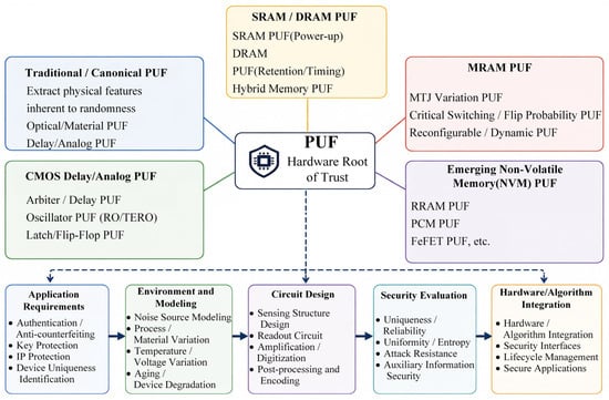
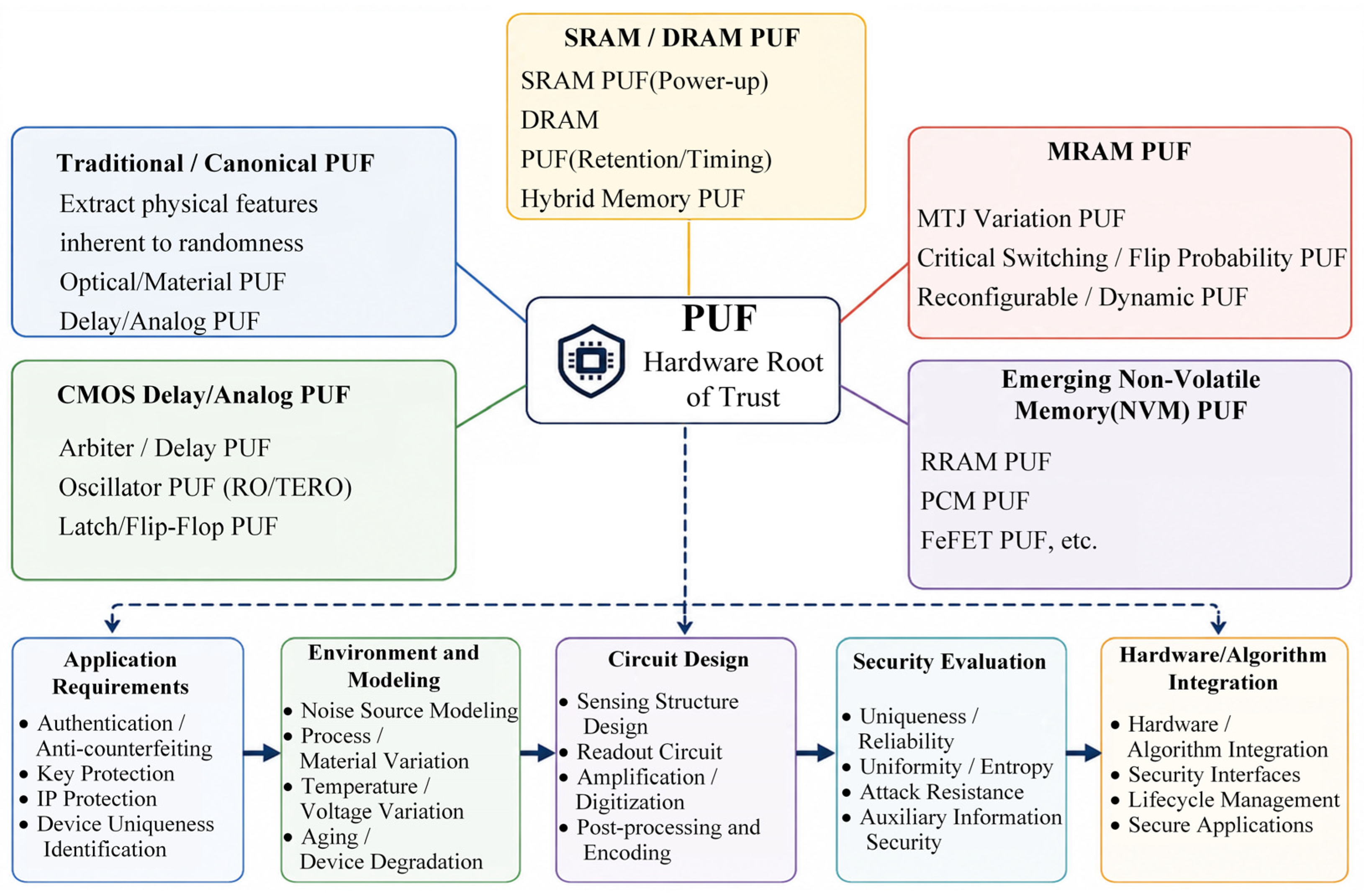
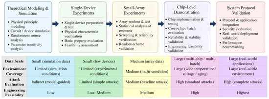
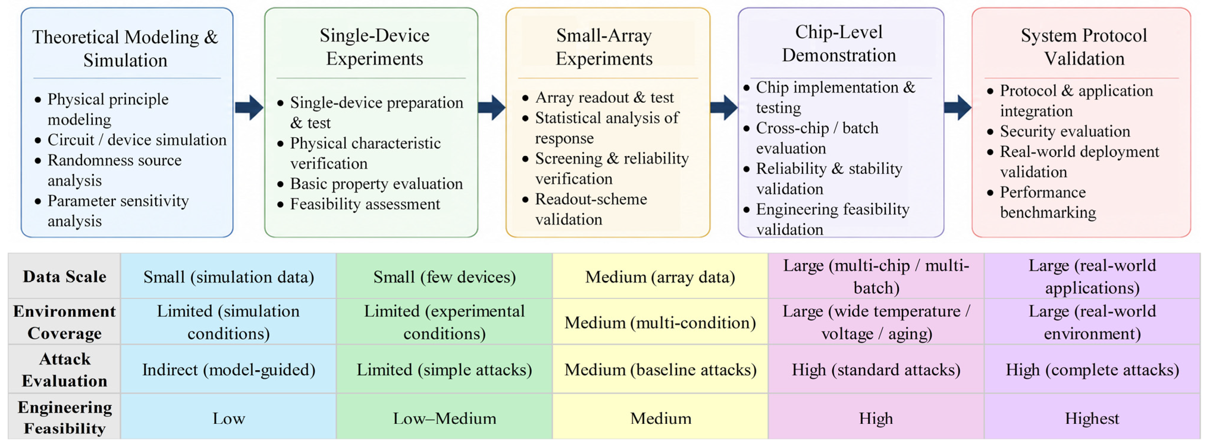
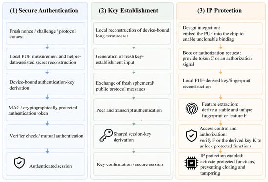
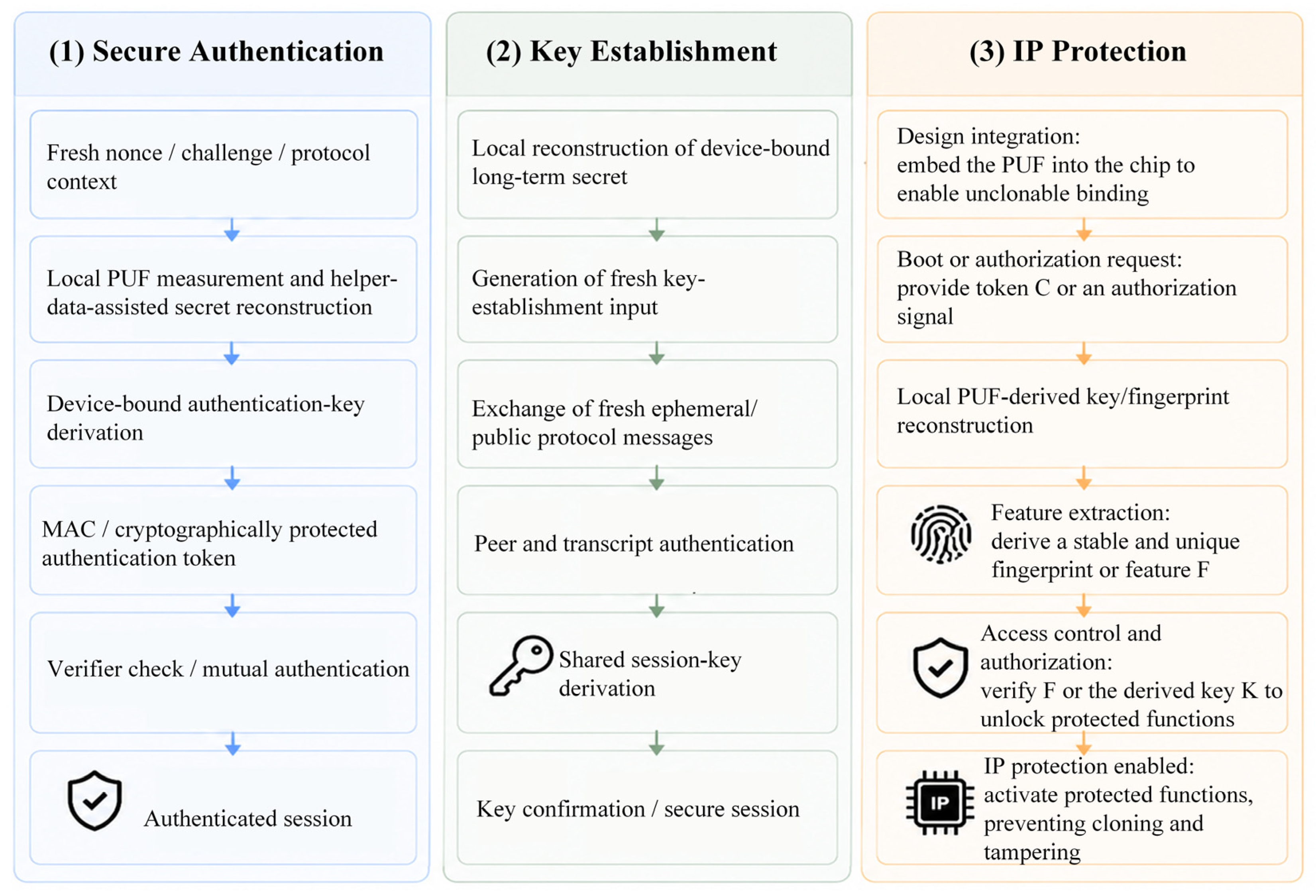
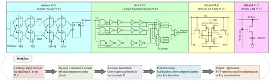
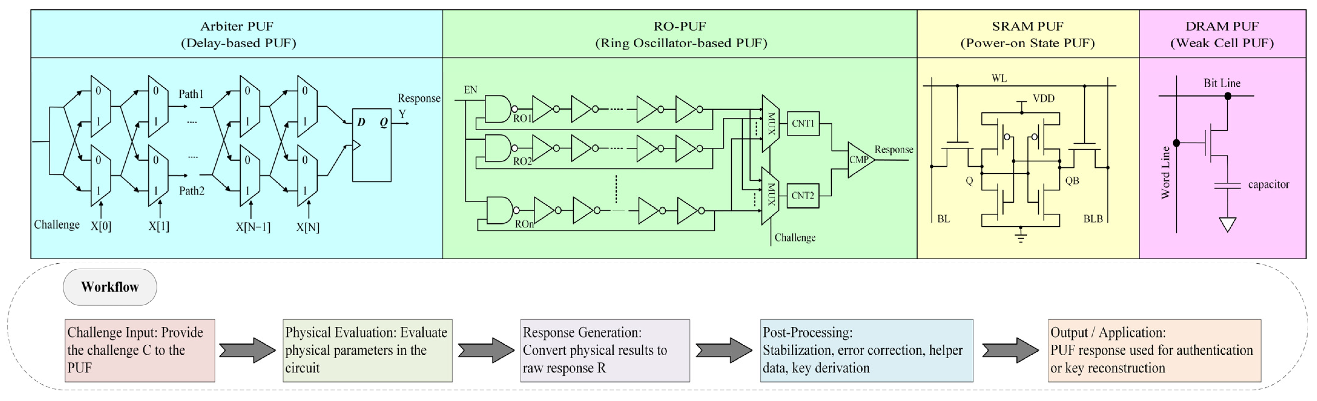
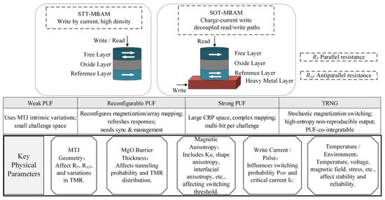
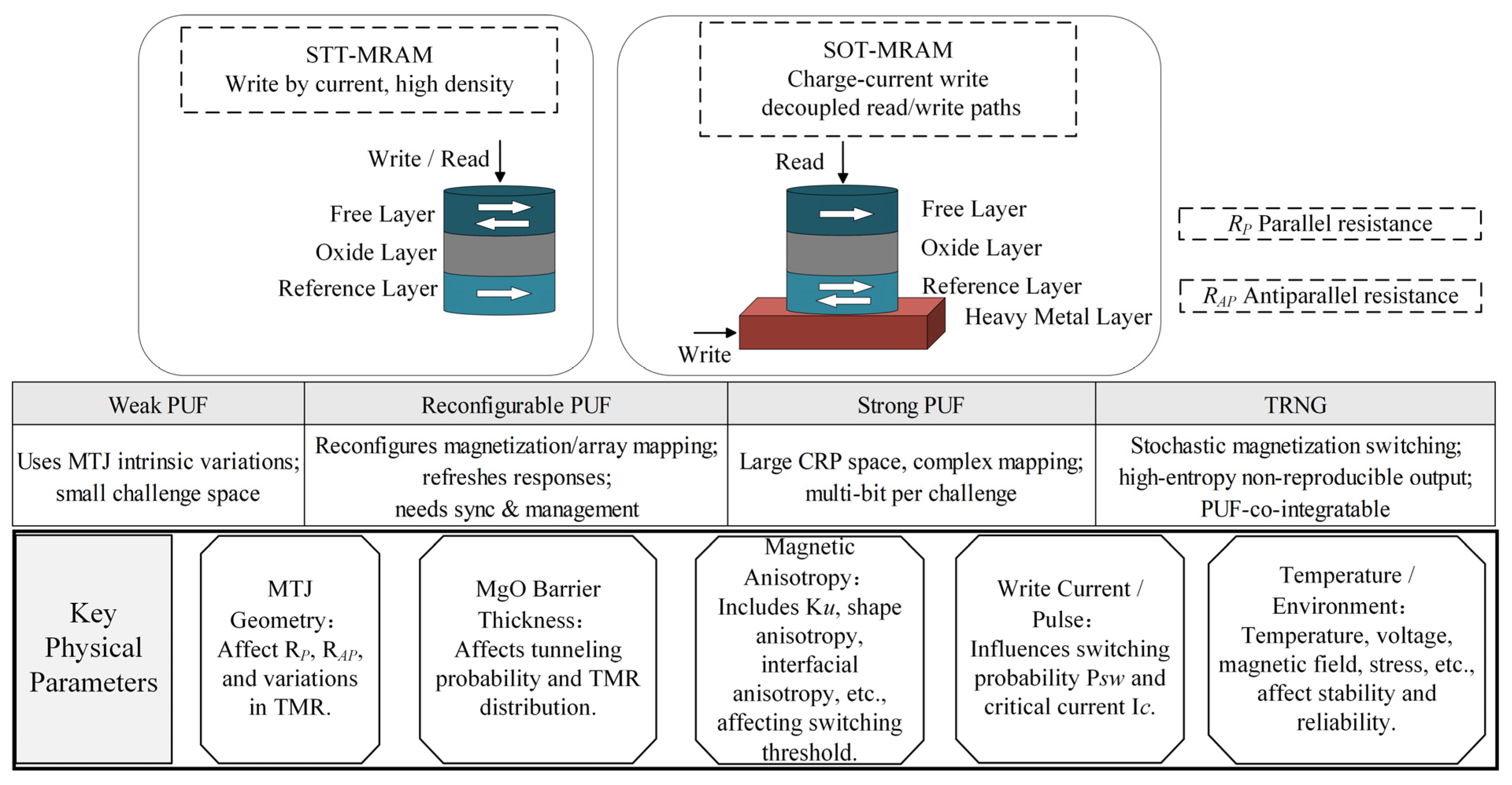
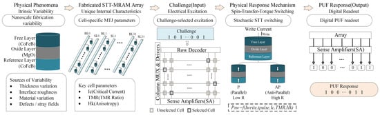
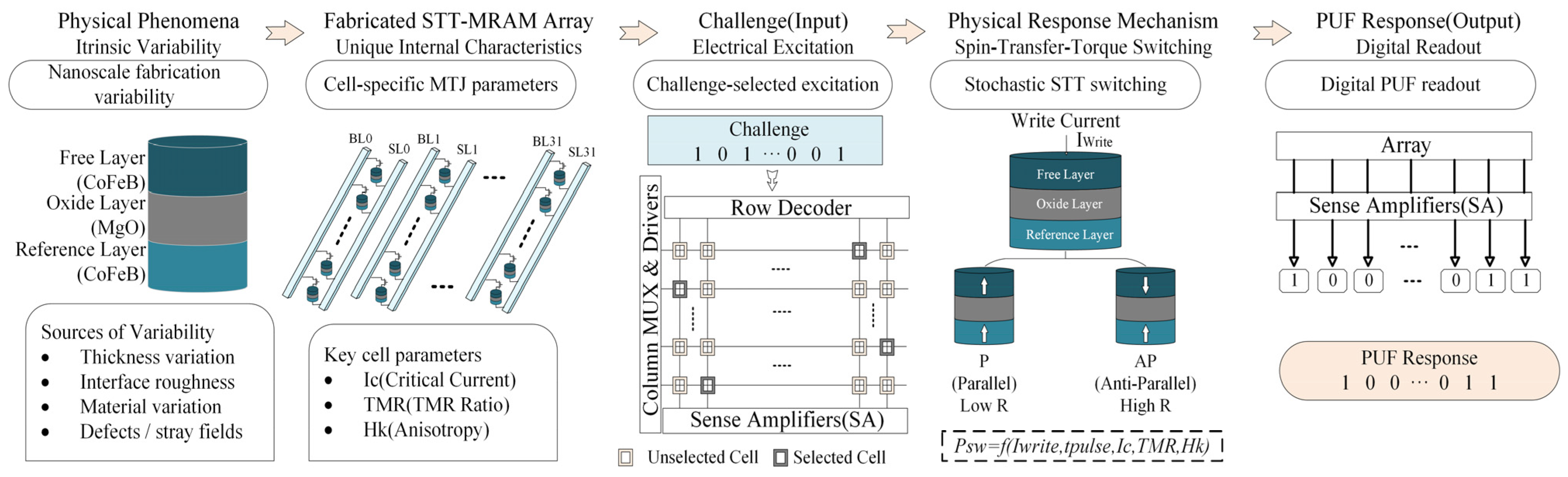
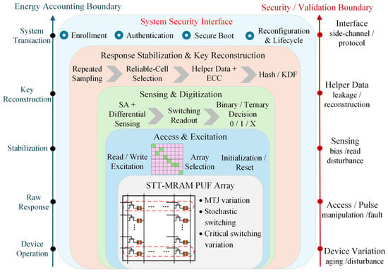
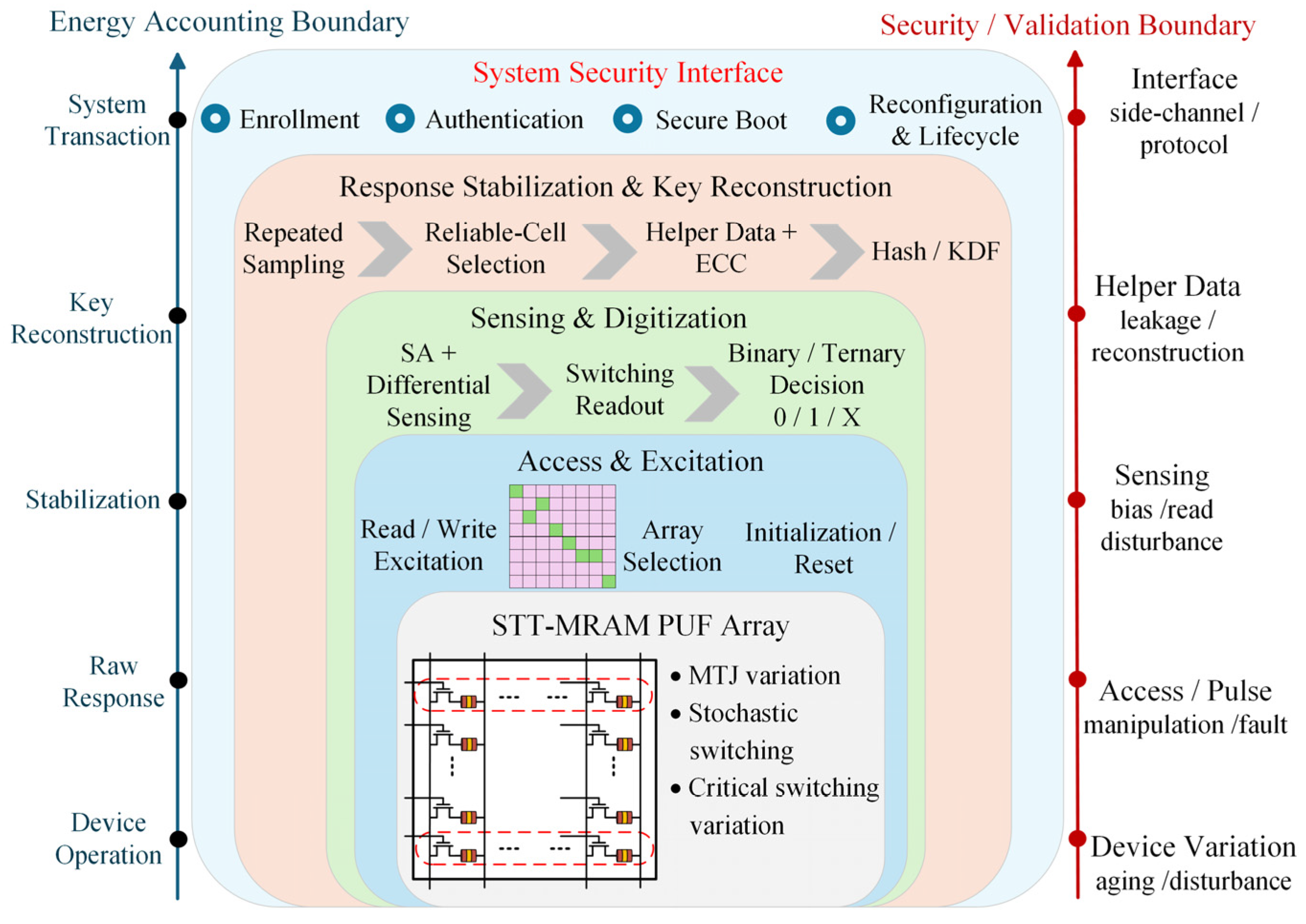
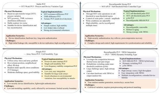
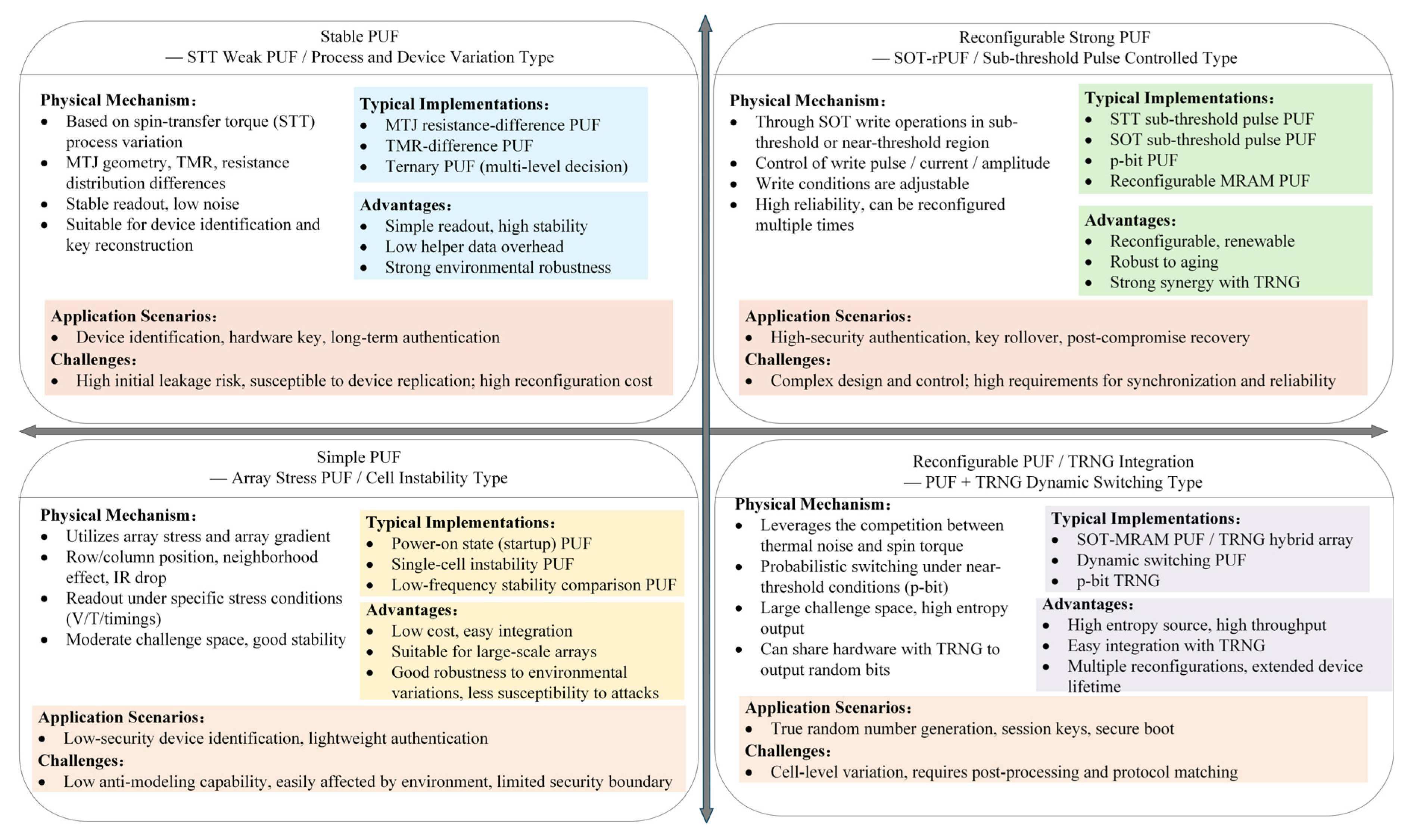
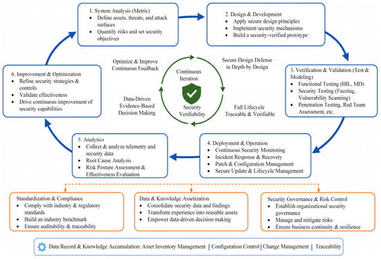
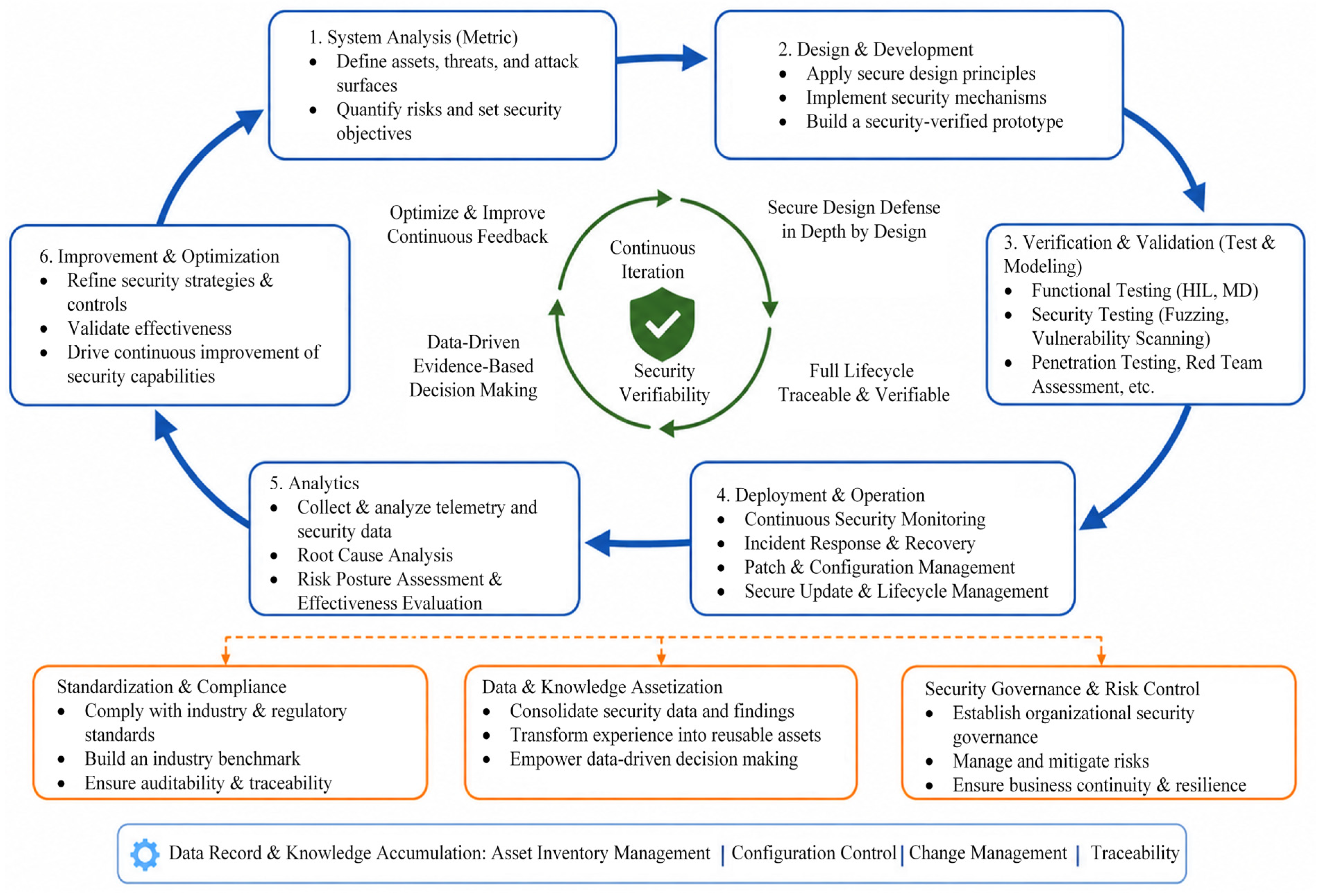

Disclaimer/Publisher’s Note: The statements, opinions and data contained in all publications are solely those of the individual author(s) and contributor(s) and not of MDPI and/or the editor(s). MDPI and/or the editor(s) disclaim responsibility for any injury to people or property resulting from any ideas, methods, instructions or products referred to in the content. |
© 2026 by the authors. Licensee MDPI, Basel, Switzerland. This article is an open access article distributed under the terms and conditions of the Creative Commons Attribution (CC BY) license.