Review

The Advancement of Solid-State Transformer Technology and Its Operation and Control with Power Grids: A Review

by
Mohammad Sazib Mollik
1,
Mahammad A. Hannan
1,*,
Md Subbir Reza
1,
Muhamad Safwan Abd Rahman
1,
Molla Shahadat Hossain Lipu
2,
Pin Jern Ker
3,
Muhamad Mansor
1 and
Kashem M. Muttaqi
4
1
Department of Electrical & Electronics Engineering, College of Engineering, Universiti Tenaga Nasional, Kajang 43000, Malaysia
2
Department of Electrical and Electronic Engineering, Green University of Bangladesh, Dhaka 1207, Bangladesh
3
Institute of Sustainable Energy, Universiti Tenaga Nasional, Kajang 43000, Malaysia
4
Faculty of Engineering and Information Sciences, University of Wollongong, Northfields Ave, Wollongong, NSW 2522, Australia
*
Author to whom correspondence should be addressed.
Electronics 2022, 11(17), 2648; https://doi.org/10.3390/electronics11172648
Submission received: 21 June 2022 / Revised: 19 July 2022 / Accepted: 20 July 2022 / Published: 24 August 2022
(This article belongs to the Section Systems & Control Engineering)

Abstract

:
Solid-state transformer (SST) technology is one of the developing technologies that will be widely used in the future to integrate low-voltage and high-voltage networks with control circuitries and power electronics converters, facilitating renewables integration in smart grid applications. SST technology has crucial key advantageous features, including compact size and weight, low cost, and ease of connection in offshore applications. However, SST technology exhibits a few concerns, such as implementation, protection, economic, and communication compatibility, that need to be addressed. This paper aims to review SST technology with its advanced control schemes and provide future directions for research and development, applications, and prospects. In line with this, highly cited SST technology papers are examined to derive and summarize concerning issues related to its operation and control with further research development of power grids. Moreover, this review discusses the assessment and state-of-the-art technology of SSTs in different applications, focusing on configurations, control circuitry, and their drawbacks and benefits. Numerous issues and challenges of SST technology are explored to identify the existing knowledge gaps and potential future recommendations. All these critical analyses, information, and evaluations would benefit power engineers and researchers in developing and implementing advanced intelligent SST technologies for sustainable energy management in future power systems.

1. Introduction

Transformers are commonly employed in power supply systems to convert AC voltage and galvanically isolate components. Smart grids are drawing the attention of many researchers recently. They are different from traditional electric networks in that they have power-generating capabilities and are able to supply electricity, especially to responsible customers in emergencies. Electricity may be generated from various sources, including nuclear power plants, autonomous diesel–electric units, large batteries, wind farms, solar panels, and hydrogen fuel cells. When employing multiple energy sources in smart grids, different stress levels should be coordinated. This is more challenging, since a portion of electrical energy is generated or stored in DC systems while the remaining is in AC systems. There are no enhancements or alterations to the classic transformer; thus, if the input voltage is asymmetrical and variations in frequency are present, there will also be an adverse effect on the output voltage. Traditional transformers need rectifiers and inverters to operate with networks that utilize a different direct or alternating current [1,2]. Solid-state transformers (SSTs) can be employed to address these concerns in smart grids, which can control and enhance the quality of electricity by compensating reactive power and reducing voltage drops. Using this technology, power supply can be adjusted without using any added compensator. SSTs are more compact, making it simpler to match varied voltage levels of direct and alternating currents. A few recent studies of SSTs with focused areas and research gaps are shown in Table 1.
SST technology connects the distribution system with the electrical users in future smart grid systems. In the smart grid system, an SST connects the medium-voltage distribution system (e.g., 12 kV AC) to the low-voltage AC distribution (e.g., 120 V AC) and/or DC distribution system (e.g., 400 V DC), as depicted in Figure 1.
When a 60 Hz conventional transformer cannot be utilized to control distributed renewable energy resources (DRER), distributed energy storage devices (DESD), or loads, the SST can be used instead. The characteristics of SSTs include immediate voltage control, voltage sag compensation, fault isolation, power factor correction, harmonic isolation, and a direct current output [7]. The 400 V DC port on the SST makes it easier to connect certain types of DRERs and DESDs [8]. Each SST, which functions as an energy router, can control active and reactive power flow as well as fault currents on both the low- and high-voltage sides. In addition, it has enormous control bandwidth capability that enables remote resources to control and respond to changes in the system quickly. According to Figure 2, an SST is made up of three parts: an active rectifier, an active bridge converter that goes in both directions from DC to DC, and an inverter [9]. The most appealing qualities of SSTs are found in the last three phases. As a result, the SST may draw a unity power factor or offer reactive compensation for voltage control when connected to the grid.
The filtering on the load side can also separate the load from transient swells and harmonic distortion on the AC grid. Another benefit of using low-voltage (LV) direct current (DC) is that it may serve as a DC bus for solar panels, energy storage devices, or electric vehicle chargers. These new capabilities and flexibility provide a foundation for future smart grid infrastructure development. However, the addition of numerous power electronic converters to a standard AC grid brings a variety of previously unrecognized control and stability difficulties. SST interactions have the potential to generate instability, which is a problem. The source output impedance interacts with the input impedance to produce this instability, manifesting as harmonic resonance. An SST’s active front end (the high-voltage (HV) rectifier) appears to the AC grid as a constant power load regardless of client load composition [10]. When the voltage drops, the power consumption reduces, making constant impedance loads self-correcting. In contrast, continuous power loads use the same amount of power and are frequently referred to as “negative impedances”, which can cause DC networks to become unstable if they are not correctly constructed [11]. While this form of instability is rare in AC distribution systems, it may become more common as SSTs become more common. Since many traditional transformers are set to be replaced by SSTs, having the ability to plug one in and start using it immediately is a plus. This paper analyzes the circumstances that may lead to SST interaction and instability and proposes a design approach to avoid this problematic behavior.
This review paper aims to distinguish and analyze the highly cited manuscripts linked to SST research. Subsequently, detailed information on methods, systems, contributions, and limitations are highlighted. Following this, outstanding issues, challenges, and future research opportunities and improvements are provided. The main contributions of this paper are outlined below:
  • To identify and analyze the highly cited papers and, accordingly, discuss the methods, analysis, and research gaps;
  • To provide state-of-the-art applications of SSTs under various domains;
  • To explore the issues and challenges of SSTs and outline the existing research limitations;
  • To provide recommendations for the future improvement of SSTs.

2. Analytical Evaluation and Discussion

For this investigation, the bibliometric database was searched using various keywords regarding “solid-state transformer”. Research on current research in grid-connected SST technology was carried out extensively using Scopus, and the top 88 citation-based papers were found. Initial search filtering was based on terms, for example, “SST control system”, “SST application”, and “grid-connected”. Secondly, the articles were arranged from highest to lowest regarding how often they have been quoted. The study examined the last ten years of data, from 2010 to 2021, followed by English language filtering for extracting contemporary research trends. Finally, the database was filtered using a “topic filter” to identify the most relevant documents. Several publications were found, but the title, abstract, focus, and citations of relevant articles were evaluated. This review’s goal is to clarify the publications on “solid-state transformer” by highlighting their unique features such as research developments, citations, assessment of the topics, and evaluation of keywords, including methods, systems, and research gaps.

2.1. Research Trends and Citation

A huge number of publications were published each year between 2010 and 2021. The rise in research shows that the sector is well-accepted and has a significant potential for implementation. Despite this, the number of articles published has decreased slightly in recent years and will continue to do so through 2020. There have been fewer papers published in recent years since it is too early to decide the article number for January of the following year. If maturity is attained, these data are dynamic, and patterns will shift. The highly cited papers on SST technology are depicted in the reference using the information on rank, keywords, methods and system, research gaps, and number of citations.

2.2. Analysis of Highly Cited Papers and Their Methods

Table 2 covers the top 10 most referenced publications in the last five years. The article by She et al. [12] is the most cited manuscript in the previous five years with 832 citations, followed by Zhao et al. [8] and Strasser et al. [13] with 521 and 407 citations, respectively. The typical research gaps in the top 10 research manuscripts include hardware optimization, experimental validation, cost analysis, system reliability assessment, and thermal and controller efficiency. In line with that, numerous vital areas are identified, including isolated bidirectional DC–DC converter modules, SST hardware and function, thermal models, winding structures, advanced control systems, optimization schemes, power quality, and reliability.

2.3. State-of-the-Art Technologies and Applications

SSTs with satisfactory performance have been designed and implemented, and efforts have been made to study how they may be applied in distribution systems. As shown in Figure 3, the transformer integrates renewable energy resources and energy storage systems [15]. The distribution system is designed using the traction/locomotive system interfaced with FACTs devices such as reactive power compensators and active power filters. In contrast, Figure 3 displays a possible future SST-based distribution system. A more integrated and compact design is achievable if the SST can replace the typical transformer and some power electronics converters. Additionally, the efficiency and cost concerns of SST technology may be valid. However, utilities are concerned about the SST-interfaced distribution system’s dependability and lifespan.

2.3.1. Voltage Conversion and Control

SSTs are used in traction systems, as seen in Figure 4 [20,21,22,23,24]. Traction systems traditionally consist of a typical power frequency transformer and a back-to-back (BTB) converter with 88–92% efficiency. The proposed structure has an efficiency of over 95%, making the system smaller and lighter. W-level power electronic traction transformers are currently in operation [20]. For example, in 2012, ABB introduced the first MW-level power electronic traction transformer in operation [20]. The smaller size means the passengers would have more room. This system also has a higher power density (0.5 to 0.75 kVA/kg) than the standard transformer plus rectifier configuration, which has a density of 0.25–0.35 kVA/kg. Solar and other renewable energy sources have a high penetration rate, such as [23,25,26,27,28,29]; in that case, an SST may be used to connect them directly to the distribution system as well. An SST takes its place, and to make the system more compact, power converters and line frequency transformers are used. On the other hand, the advantages of the SST concept have been highlighted in terms of power quality, protection, and deep rural feeder (SWER) applications. The SST topology will improve power quality [30]. Although, the significant enhancement will help SST customers. Among the most prominent advantages are:
(a)
The SST is powered by an intermediate DC energy storage capacitor, from which the output voltage is generated. The voltage of the DC capacitor may be controlled by the front-end converters across a broad input range;
(b)
The output inverter has a control loop for the output voltage, which means that the output voltage will be the same no matter what the load is. This means that the voltage regulation is almost perfect;
(c)
The input of the SST will simulate a variable resistance, with the resistance varying according to the output power required and the input current being sinusoidal and in phase with the voltage. The SST concept will benefit distributions systems utilizing SWER technology [30].
Figure 5 shows an example of a wind energy system using a squirrel cage induction generator [12]. A reactive power compensator may be required for this system to keep the common connection voltage stable. A new wind energy system, depicted in Figure 5, may be created by combining the active power transfer, reactive power compensation, and voltage conversion operations of an SST.
This single SST essentially substitutes two transformers: one STATCOM and a local capacitor [23]. The cost difference between a single SST and a regular transformer will be reduced due to this development. SST acts as a system that interfaces with the wind energy system. It is also possible to include energy storage devices when a DC link is provided for the SST. With the use of SST technology, EPRI has shown a 45 kVA, 2.44 kV rapid charging station. The electric car is charged using a typical method that uses a transformer, an AC–DC converter, and a DC–DC converter with an efficiency of about 90%. However, the efficiency may be increased to >95% by utilizing SST technology. Additionally, it can cut weight and cost by up to half, compared to current technology, making it far superior in every way [31].
Smart grid technologies integrated into energy storage systems will be more critical in future distribution networks as the need for renewable sources of energy grows. Because of this, the SST is suitable for use in both microgrids and universal interfaces for distributed energy resource integration. According to a number of sources, the SST’s possible benefits have been examined in [12,32,33,34]. In general, it is believed that SST technology will not only be used in substitution for traditional transformers, but will also have other capabilities that may significantly increase the quality of the electricity. The application of SST technology in future intelligent distribution systems is denoted in Figure 6. The proposed system can be further extended to apply in a traction system, rapid charger connection for direct current, or a distributed energy source with or without energy storage systems [35], when it comes to microgrid architectures [36], or any form of load that can benefit from reactive power correction and active harmonic filtering.

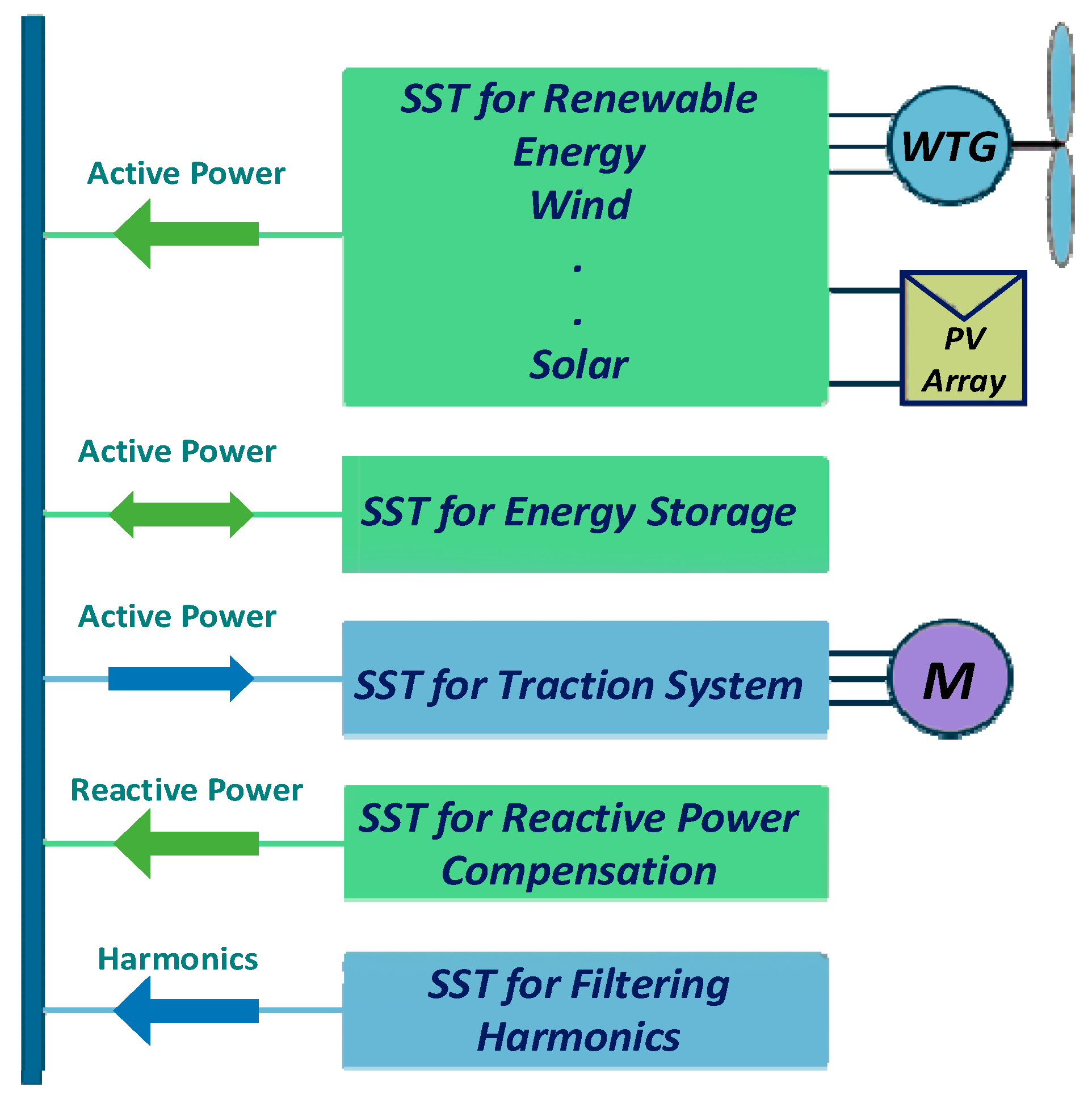
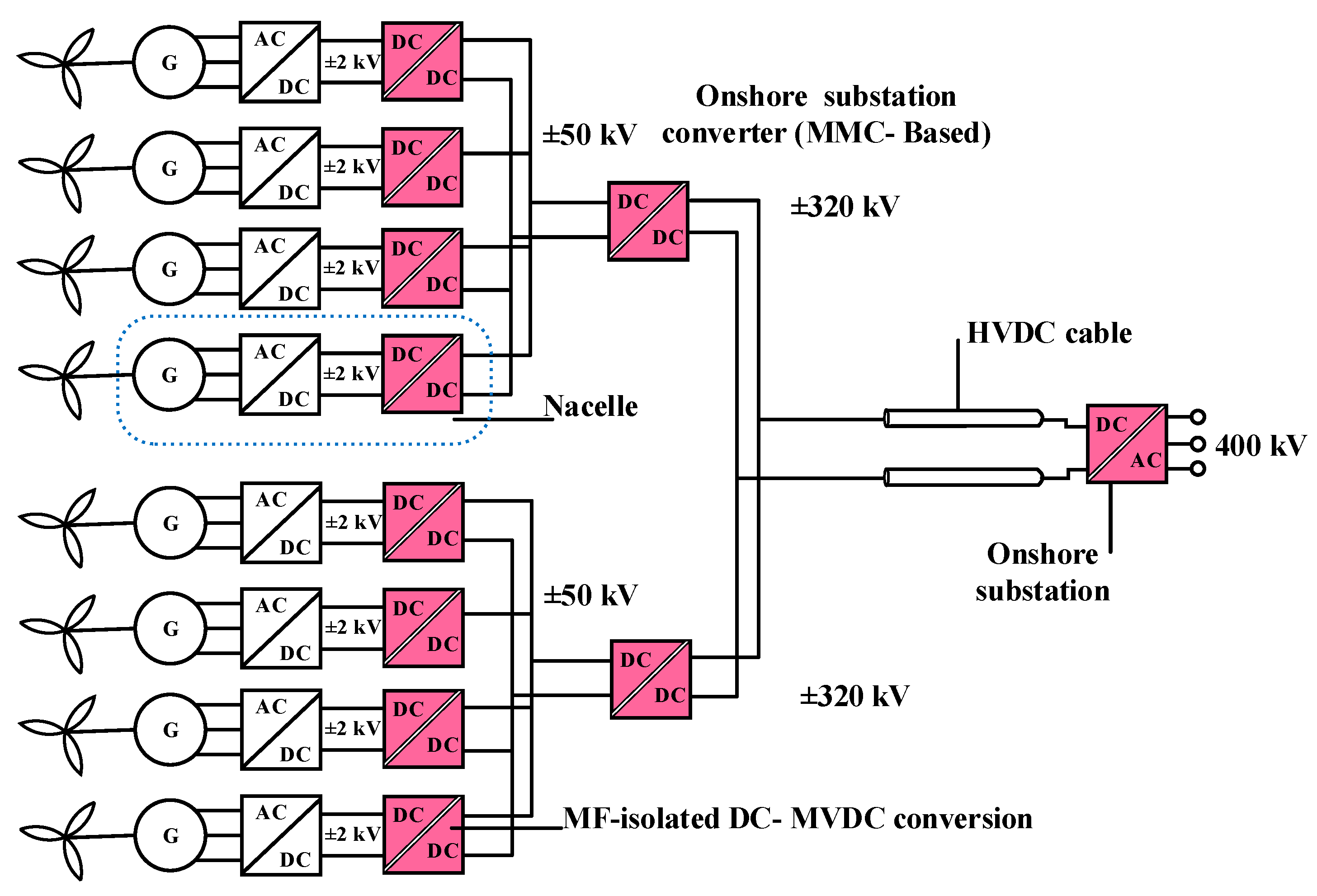
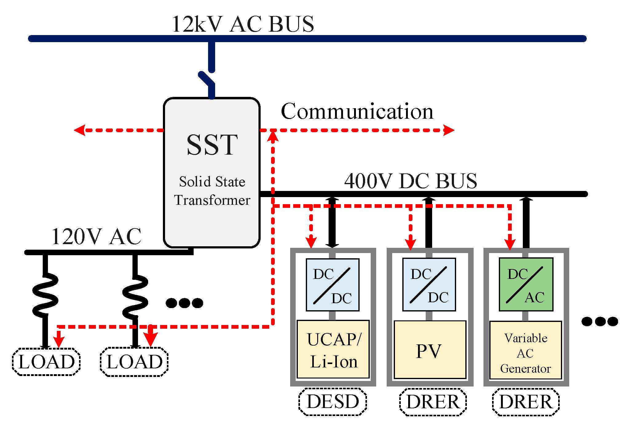
2.3.2. SST Technology in the Future Grid

The future renewable electric energy delivery and management (FREEDM) system, which connects the distributed renewable energy resources in a plug-and-play manner, and the future generation of power distribution systems were proposed in [25]. The FREEDM system is a highly appealing contender for future power distribution systems; for further information, read the references [37,38,39,40,41]. Reference [42] suggested hybrid microgrids employing SST technology: Dual-phase shift control is used in the isolated bidirectional DC–DC converter to minimize circulating current and boost efficiency. To prevent control coupling, the isolation unit is in charge of managing voltage and power balance. Commercially accessible SiC-based semiconductors are used in the converters, and iron-based nanocrystalline soft magnetic material is used to create the high-frequency magnetic components. A multilayer cascade arrangement makes up the high-voltage grid interface. The study in [43,44] examined the effectiveness of energy routers in SST technology applications in future smart grids.

2.3.3. SST Technology in Traction System

With each new generation of trains, the weight and size constraints on the traction transformer become more stringent, putting a premium on dependability and efficiency. Therefore, SST technology is a possible alternative to an extensive 162/3 Hz railway system for low-frequency transformers. In reference [45], SST technology for traction applications was offered in a high-level overview. The multilayer converter presented in had decreased weight and dimension and a lower global life cycle cost; the multilevel topology included 16 bidirectional direct current converters (cycloconverters). A catenary would power these converters with a voltage of 15.7 kV and a frequency of 16.7 Hz, and 16 medium-frequency transformers (400 Hz) driven by 16 four-quadrant converters attached in parallel to a 1.8 kV DC connection are connected to a choke inductor. Refer to these sources for further information on SST use in traction systems [22,46].

2.3.4. Other Applications

SST technology can be utilized in other applications. For example, a single-stage bidirectional SST can be employed in induction heating applications [47]. The configurable switching frequency controller in the SST allows it to follow the maximum power point while also improving the output power factor. Reference [48] presented a lighting system using a single-stage bidirectional SST: Galvanic isolation is provided in each unit via a single-input multi-output HFT in the SST. The system feeds numerous light units that simultaneously use a PWM approach to control the SST. As a result, the fluorescent lights may operate without voltage flicker or disturbances with the control strategy, improved efficiency, low mass/weight, and compact volume designs, eliminating the need for bulky storage parts. This improves lighting while also protecting and extending the lamp’s lifespan. Figure 7 shows a high-frequency transformer in SST-based conversion systems replacing the 50/60Hz-based frequency transformer [49].
To fulfil the most recent grid code standards, the SST provides enough control. Therefore, the grid-side converter (GSC) can be removed, making the system lighter and more efficient, leading to numerous advantages such as stator terminal voltage stabilization, optimizing the voltage profile, and efficient active and reactive power transfer. Furthermore, there is no requirement for an additional compensator to adjust reactive power. Moreover, it can be operated at a high frequency, resulting in a small volume and weight and a low cost [50]. Table 3 summarizes the advantages of SST technology for future electrical systems.

2.3.5. AC–DC Applications

The LV-side DC–AC conversion step of the SST is not required for a fast-charging station for electric vehicles (EVs) that may also offer grid ancillary services when not in use, or directly power servers in a datacenter from the MV grid. However, a bidirectional LFT must be extended via an LV DC link to connect the PV production plant or the more extensive energy storage facility to the MV grid [56,57,58]. In addition, the presence of a DC output frequently implies that the LV DC side environment does not exist today, but may be co-designed in a way that is compatible with the SST. For example, Figure 8 displays a wide range of AC–DC applications.

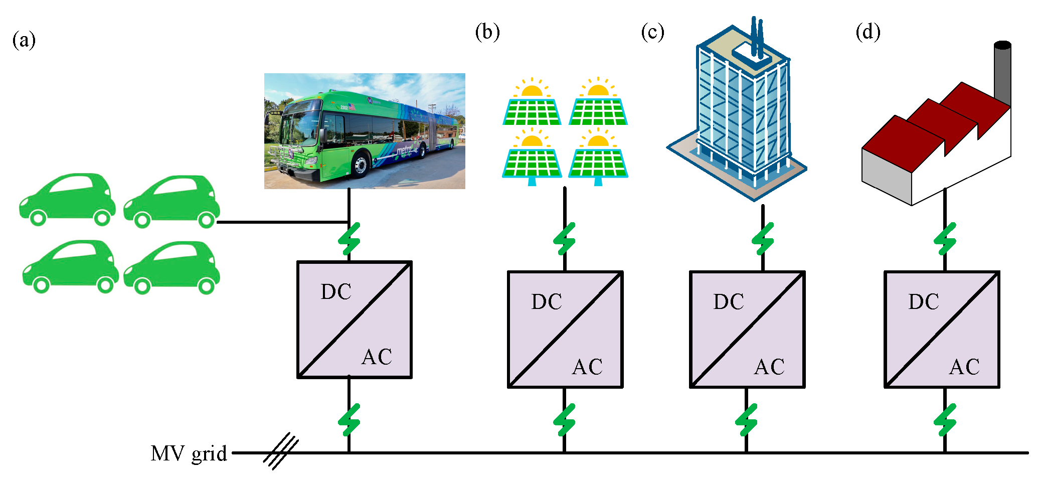
2.3.6. Weight/Space-Limited Applications

Traction-related applications severely hamper the isolation stage’s weight and space requirements. Since multiple firms are working on single-phase (AC–DC) SST traction applications, many prototypes have been built and field tested on Swiss railroads, including an SST-equipped shunting locomotive [59]. The use of SSTs with low-complexity topologies, such as those used in temperature control units, might potentially be investigated for railway auxiliary MVAC–LVDC power supply (on the order of 25 kW to 50 kW) [60]. Another example of a place where a weight and space constraint may apply is the nacelles of wind turbines [44,61,62], or even flying wind turbines [63]; for future navy warships [64], in addition to future civilian ships such as cruise lines [65,66], onboard electricity will be distributed via local MVAC and/or MVDC networks. MVAC might be useful in various low-weight and low-volume subsea SST systems. Further, it can be used in oil drilling infrastructure and future subsea applications and MVDC links to the surface or the coast [67,68].

2.3.7. DC–DC Applications

Figure 9 depicts a DC collection grid for offshore wind turbines [69,70]. Magnetic transformers are necessary for galvanic isolation and substantial voltage increases/decreases in these DC distribution networks. A transformer, however, requires an AC voltage to function. As a result, conversion stages from DC to AC and AC to DC are necessary, and modification of transformer working frequency may be executed. Furthermore, since no AC voltage can be utilized to power the transformer in an AC–AC or AC–DC application, further conversion stages are necessary for both circumstances. As proposed, offshore wind farms will benefit from a DC collection grid [70].

2.3.8. AC–AC Flyback Applications

In order to support bipolar voltage and current, many DC–DC converter topologies can be transformed into AC–AC converters by removing part or all of the switches and replacing them with four-quadrant switches. This AC–AC converter is developed from the flyback, which is the most basic isolated DC–DC converter architecture, as seen in Figure 10. It has the fewest switches per module of any device [71]; nevertheless, it requires twice as many modules as the prior single-stage structure since it roughly doubles the voltage stress on the switches.

2.3.9. AC–DC Isolated Boost + PWM Inverter Applications

The isolated DC–DC version of the isolated boost converter serves as the foundation for this SST architecture; hence, its large-signal average model is identical [71]. The duty cycle of the PWM voltage at the input terminals must be adjusted appropriately in order to generate a sinusoidal input current. In order to sustain bipolar voltage and current, the switches on the high side must have four quadrants. Figure 11 depicts a single AC–DC module in this configuration. The DC–AC stage is a two-phase inverter that enables bidirectional power transmission between the LVDC connection and the AC buses. Compared to a regular H-bridge converter, it has an extra leg, driven by a gate signal with a constant 50% duty cycle [71].
Case I studies the system under the grid-connected mode, where a full-load situation is permitted. The wind generator is operated in the MPPT mode. The wind speed is first set as 10 m/s, and the PMSG is operated at 168.9 rad/s, which corresponds to 1.11 p.u. At 2 s, v w begins to increase, which causes the extracted wind power to increase [33].
Case II investigates how the system performs with mode transition from the grid-connected mode to the islanding mode. As the system is disconnected from the power grid at 2 s, surplus power that cannot be consumed by the load will cause the DC-link voltage to increase [33]

3. Issues and Challenges of SST Technology

3.1. Conversion Efficiency Challenge

LFTs in distribution grids are primarily responsible for providing galvanic isolation and voltage scaling while incurring as few losses as possible. As a result, for the majority of the load range, typical oil-filled 1000 kVA LFT efficiencies exceed 99% (see Figure 12) according to [13]; taking other manufacturers into account produces similar findings.
On the other hand, an AC–AC SST contains two AC–AC converter stages, one on each side of the primary voltage and voltage supply: one for the main voltage and one for the low voltage (LV) (as seen in Figure 13). Based on the provided LFT and MFT efficiencies and assuming that the two AC–AC converter stages have identical efficiencies (i.e., SST, MV = SST, LV), The efficiencies of the AC¬¬–AC stages required to obtain an overall SST efficiency equal to an LFT, i.e., SST = LFT, are determined in this research. This relationship is seen in Figure 12 when varied MFT efficiencies are considered [17]. The choice of an optimal switching frequency is critical to this efficiency and the active material size. It is essential to keep in mind that MFTs may get away with using less material and being more efficient than LFTs because their prices are lower. It is important to note that even with a high-efficiency MFT (ηMFT = 99.6%), getting to the desired total MV-to-LV efficiency of 99.5% necessitates 99.7% efficiencies in both AC–AC conversion stages (Figure 14). As you can see, this is a lofty goal that will likely remain unachievable with current high-power converters.

3.2. Cost Challenge

According to pricing information collected from a prominent European transformer manufacturer, LFTs are off-the-shelf commodities with a specified (selling) price between cLFT = 10 $/kVA and 25 $/kVA for 1000 kVA units [72]. The price will differ based on the optimization goal, such as low losses or cheap costs; for instance, there are not any SST products on the market that allow you compare their pricing side by side. Therefore, [73] SST materials are estimated to be at least five times more expensive than LFT materials for a 1000 kVA SST.
A product’s cost of production does not have to be directly tied to the price because there may be other factors at play, such as compensation for development expenses, labor expenses in manufacturing, infrastructure costs, and profit margins, among other things. Since high-power converter systems are widely accessible, their pricing may be used to estimate the cost of an SST. An SST’s LV inverter (as depicted in Figure 15) is essentially the same as a high-power drive’s active front-end (AFE) converter, such as the Altivar 61 series from Schneider Electric [13].
For these converters, price information is available, and a 1000 kVA unit costs roughly cSST,LV = 125 $/kVA [13]. Furthermore, [74] The cost of the utility-scale (500 kVA) PV inverters ranges from 100 to 120 euros per kVA (114 to 137 dollars per kVA).
Because the MV-side converter section (see Figure 15) is more complicated and must interface with MV as well as contain the MF isolation stage, it is reasonable to suppose that the MV-side converter’s particular price is greater than the LV-side converter’s, i.e., cSST,MV > cSST,LV. For example, an AC–AC SST is estimated to cost at least 10 to 25 times more than an equivalent-rated LFT, according to Figure 16a. Figure 16b shows a comparison of a 500 kVA LV inverter’s projected material costs with list price information as in [13,75].
The weight and material cost structures of the MV converter, the LV converter, and the combined 1000 kVA AC–AC SST are shown in Figure 17. It is noteworthy that low-frequency magnetic components, such as filter inductors, continue to account for a sizable portion of both weight and material costs, particularly in the case of LV converters, where high phase currents necessitate large copper conductor material requirements. Consequently, these passive filter components are of special importance for future cost and weight reductions of SSTs. However, future technologies such as silicon carbide (SiC) are anticipated to considerably contribute to additional weight reduction via greater switching frequencies and subsequently smaller passive component sizes. Medium-frequency transformers and power semiconductors also contribute significantly to material expenses [73].

3.3. Compatibility Challenge

Most of the time, fuses and circuit breakers that may be programmed are used to safeguard low-voltage grids against short circuits. When an issue arises, only the nearest upstream protection device should activate, limiting the grid’s impact to the lowest possible region. In this defense strategy, selectivity is crucial. Figure 18a depicts a simplified form of a hierarchically arranged LV grid and associated protective devices. To achieve selectivity, fuse ratings are low near end-users and higher near the feeding transformer. Figure 18b depicts the relationship between melting time and current consumption for a common low-voltage (LV) fuse [76], a fuse with a lower-rated current trips before a fuse with a higher rating when a short circuit develops, indicating that a short circuit occurred. Even a similarly small 250 A fuse would take a long time to light, for which, within a reasonable time, a current of around 1.5IN may be required to safeguard a load on a lower hierarchical level of the LV grid, as illustrated in Figure 18b. A short-circuit current that is several times the rating value is needed for fuses that are closer to the feeding transformer because they are installed at the higher level of the LV grid’s hierarchical structure. This is particularly true for the transformer safety fuses, which are positioned close to the transformers. The transformers at the MV grid’s interface must provide the short-circuit current needed. There is a two-second time limit on the maximum current that LFTs should be able to supply [77].
In contrast, a power electronic system cannot achieve this without significantly overrating the power devices due to the power semiconductor chip thermal time constants, which are only 10 to 50 milliseconds; additionally, the filter inductors would need to have a correspondingly high saturation limit. [78]. On the other hand, an SST might restrict the current flow during a short circuit. However, security ideas are necessary to make use of this intriguing capability. Communication between the breakers, SST, or other grid-connected switching devices is regularly employed in these intricate protection approaches. [79,80,81,82]. This means that an SST would have to be used with an LFT in the distribution grid because the present protection architecture could not be used any longer. As opposed to this, an SST needs a grid environment tailored to the SST’s special properties such as communication between protection relays. However, implementing such changes would be difficult in current distribution systems, and they would be costly.

3.4. System Topologies

The topologies of current converters designed for railway traction applications were investigated. Numerous alternative topologies, on the other hand, such as isolated AC-to-AC converter topologies, can be identified by a survey and study of isolated converter topologies [83,84,85,86,87,88,89,90]. Smart grid and renewable energy applications research is now gaining pace. Due to commonality in high power, medium voltage, and galvanic isolation, PET-based systems intended for smart grid and renewable energy applications are highly likely to be transferred to railway traction applications.

3.5. Other Issues

Beyond the three critical problems outlined above, blockchain is an emerging technology that faces several other challenges. The operating frequency and the number of cascaded modules’ optimization may be less complicated. However, it still requires more investigation, as do the techniques of soft switching and control and system dependability and protection. Furthermore, these problems might impact one another and form a symbiotic relationship. For example, with the advancement of power devices, we may create new converter topologies and increase the number of cascaded modules and power devices we have. As a result, rather than focusing on an individual component, it is critical to assess the impacts at the system level.

4. Conclusions and Future Directions

This review paper presents an overview of SSTs in various applications—first, the paper analyzes the top-cited reports emphasizing the contributions, methods, and research gaps. Secondly, the paper explains the application of SST technology in different fields and highlights operations, benefits, and drawbacks. Thirdly, various key issues and challenges are explored elaborately. Finally, the review provides a few practical future suggestions for the further advancement of SST technology in future power systems, operation, and management mentioned below:
  • The financial assessment of SST technology needs to be explored and evaluated for the calibration, filtering, protection, communication, validation, cybersecurity, and power quality requirements. In addition, study on the cost-effective emerging power electronics technology integrated into SSTs will be necessary to replace the conventional transformer towards the advancement of SST technology in the future;
  • SST technology could be employed to operate and control the functionalities and routing in the distribution system of the smart grid. Thus, further investigation is required to enhance the reliability, power quality, efficiency, and reactive power compensation;
  • SST technology could be a promising solution for grid-integrated renewable power management in next-generation electric power systems. SST technology with an efficient energy router and a high level of functionalities can be employed to examine the effectiveness under various domains, including grid intelligence, power electronics, communications, and network protocol requirements;
  • The efficiency and validation of SST technology could experience stability and reliability issues. Thus, further attention is required to design and develop accurate and robust algorithms, models, control schemes, and optimizations to enhance efficiency. It is also necessary to assess the performance of the methods and the behavior under different operational settings;
  • The protection of SST technology needs further evaluation under the circumstances of overcurrent and overvoltage cases. Thus, advanced protection schemes with enhanced control function as well as filter and protective relays could play a crucial role to prevent blackouts under fast load reduction approaches;
  • The communication between SSTs and power devices in real time is vital to address the information and transmission exchange problems. Hence, an intelligent energy information structure is required for the advanced compatible communication system to overcome the reliability, security, and transmission latency concerns.
These suggestions can provide appropriate guidelines and opportunities to power engineers and researchers to develop advanced intelligent SSTs, their applications, operation, and control schemes in achieving high-efficiency SSTs.

Author Contributions

M.S.M. and M.S.R.; resources, M.S.A.R.; writing—original draft preparation, K.M.M. and P.J.K.; writing—review and editing, M.S.R. and M.S.H.L.; visualization, M.A.H.; supervision, M.A.H.; project administration, M.A.H. and M.M.; funding acquisition. All authors have read and agreed to the published version of the manuscript.

Funding

This research and the APC was funded by Universiti Tenaga Nasional through UNITEN Bold Refresh 2025 Grant, Centre of Excellent. The research is associated with Institute of Power Engineering. Special thanks to Faculty of Engineering and Information Sciences, University of Wollongong for providing collaborative support.

Conflicts of Interest

The authors declare no conflict of interest.

References

  1. Almaguer, J.; Cárdenas, V.; Espinoza, J.; Aganza-Torres, A.; González, M. Performance and control strategy of real-time simulation of a three-phase solid-state transformer. Appl. Sci. 2019, 9, 789. [Google Scholar] [CrossRef]
  2. Chernyi, S. Techniques for selecting topology and implementing the distributed control system network for maritime platforms. AKCE Int. J. Graphs Comb. 2018, 15, 219–223. [Google Scholar] [CrossRef]
  3. Monteiro, V.; Oliveira, C.; Afonso, J.L. A Multilevel Bidirectional Four-Port DC-DC Converter to Create a DC-Grid in Solid-State Transformers with Hybrid AC/DC Grids. In Proceedings of the International Young Engineers Forum (YEF-ECE), Caparica/Lisboa, Portugal, 9 July 2021; pp. 26–31. [Google Scholar]
  4. Monteiro, V.; Pedrosa, D.; Coelho, S.; Sousa, T.; Machado, L.; Afonso, J.L. A Novel Multilevel Solid-State Transformer for Hybrid Power Grids. In Proceedings of the International Conference on Smart Energy Systems and Technologies (SEST), Vaasa, Finland, 6–8 September 2021; pp. 1–6. [Google Scholar]
  5. Shadfar, H.; Ghorbani Pashakolaei, M.; Akbari Foroud, A. Solid-state transformers: An overview of the concept, topology, and its applications in the smart grid. Int. Trans. Electr. Energy Syst. 2021, 31, e12996. [Google Scholar] [CrossRef]
  6. Monteiro, V.; Martins, J.S.; Fernandes, J.C.A.; Afonso, J.L. Review of a Disruptive Vision of Future Power Grids: A New Path Based on Hybrid AC/DC Grids and Solid-State Transformers. Sustainability 2021, 13, 9423. [Google Scholar] [CrossRef]
  7. Shi, J.; Gou, W.; Yuan, H.; Zhao, T.; Huang, A.Q. Research on voltage and power balance control for cascaded modular solid-state transformer. IEEE Trans. Power Electron. 2011, 26, 1154–1166. [Google Scholar] [CrossRef]
  8. Zhao, T.; Wang, G.; Bhattacharya, S.; Huang, A.Q. Voltage and power balance control for a cascaded H-bridge converter-based solid-state transformer. IEEE Trans. Power Electron. 2013, 28, 1523–1532. [Google Scholar] [CrossRef]
  9. Shah, D.G.; Crow, M.L. Stability design criteria for distribution systems with solid-state transformers. IEEE Trans. Power Deliv. 2014, 29, 14759118. [Google Scholar] [CrossRef]
  10. Bottrell, N.; Prodanovic, M.; Green, T.C. Dynamic stability of a microgrid with an active load. IEEE Trans. Power Electron. 2013, 28, 5107–5119. [Google Scholar] [CrossRef]
  11. Onwuchekwa, C.N.; Kwasinski, A. Dynamic behavior of single-phase full-wave uncontrolled rectifiers with instantaneous constant-power loads. In Proceedings of the IEEE Energy Conversion Congress and Exposition, Phoenix, AZ, USA, 17–22 September 2011; pp. 3472–3479. [Google Scholar]
  12. She, X.; Huang, A.Q.; Burgos, R. Review of solid-state transformer technologies and their application in power distribution systems. IEEE J. Emerg. Sel. Top. Power Electron. 2013, 1, 186–198. [Google Scholar] [CrossRef]
  13. Strasser, T.; Andrén, F.; Kathan, J.; Cecati, C.; Buccella, C.; Siano, P.; Leitão, P.; Zhabelova, G.; Vyatkin, V.; Vrba, P.; et al. A review of architectures and concepts for intelligence in future electric energy systems. IEEE Trans. Ind. Electron. 2015, 62, 2424–2438. [Google Scholar] [CrossRef] [Green Version]
  14. Huber, J.E.; Kolar, J.W. Solid-state transformers: On the origins and evolution of key concepts. IEEE Ind. Electron. Mag. 2016, 10, 19–28. [Google Scholar] [CrossRef]
  15. Huber, J.E.; Kolar, J.W. Applicability of solid-state transformers in today’s and future distribution grids. IEEE Trans. Smart Grid 2017, 10, 317–326. [Google Scholar] [CrossRef]
  16. Costa, L.F.; De Carne, G.; Buticchi, G.; Liserre, M. The smart transformer: A solid-state transformer tailored to provide ancillary services to the distribution grid. IEEE Power Electron. Mag. 2017, 4, 56–67. [Google Scholar] [CrossRef]
  17. Leibl, M.; Ortiz, G.; Kolar, J.W. Design and experimental analysis of a medium-frequency transformer for solid-state transformer applications. IEEE J. Emerg. Sel. Top. Power Electron. 2017, 5, 110–123. [Google Scholar] [CrossRef]
  18. Chen, H.; Divan, D. Soft-switching solid-state transformer (S4T). IEEE Trans. Power Electron. 2018, 33, 2933–2947. [Google Scholar] [CrossRef]
  19. Feng, J.; Chu, W.Q.; Zhang, Z.; Zhu, Z.Q. Power electronic transformer-based railway traction systems: Challenges and opportunities. IEEE J. Emerg. Sel. Top. Power Electron. 2017, 5, 1237–1253. [Google Scholar] [CrossRef]
  20. Dujic, D.; Zhao, C.; Mester, A.; Steinke, J.K.; Weiss, M.; Lewdeni-Schmid, S.; Chaudhuri, T.; Stefanutti, P. Power electronic traction transformer-low voltage prototype. IEEE Trans. Power Electron. 2013, 28, 5522–5534. [Google Scholar] [CrossRef]
  21. Drabek, P.; Peroutka, Z.; Pittermann, M. New configuration of traction converter with medium-frequency transformer using matrix converters. IEEE Trans Ind. Electron. 2011, 58, 5041–5048. [Google Scholar] [CrossRef]
  22. Claessens, M.; Dujic, D.; Canales, F.; Steinke, J.K.; Stefanutti, P.; Vetterli, C. Traction transformation. Energize 2013, 1, 11–17. [Google Scholar]
  23. She, X.; Huang, A.Q.; Wang, F.; Burgos, R. Wind energy system with integrated functions of active power transfer, reactive power compensation, and voltage conversion. IEEE Trans. Ind. Electron. 2013, 60, 4512–4524. [Google Scholar] [CrossRef]
  24. Tatcho, P.; Jiang, Y.; Li, H. A novel line section protection for the FREEDM system based on the solid state transformer. In Proceedings of the IEEE Power and Energy Society General Meeting, Detroit, MI, USA, 24–28 July 2011; pp. 1–8. [Google Scholar]
  25. Brando, G.; Dannier, A.; Del Pizzo, A.; Rizzo, R. A high performance control technique of power electronic transformers in medium voltage grid-connected PV plants. In Proceedings of the XIX International Conference on Electrical Machines-ICEM, Rome, Italy, 6–8 September 2010; pp. 1–6. [Google Scholar]
  26. Sabahi, M.; Goharrizi, A.Y.; Hosseini, S.H.; Sharifian, M.B.B.; Gharehpetian, G.B. Flexible power electronic transformer. IEEE Trans. Power Electron. 2010, 25, 2159–2169. [Google Scholar] [CrossRef]
  27. Fan, H.; Li, H. High-frequency transformer isolated bidirectional DC–DC converter modules with high efficiency over wide load range for 20 kVA solid-state transformer. IEEE Trans. Power Electron. 2011, 26, 3599–3608. [Google Scholar] [CrossRef]
  28. Rashidi, M.; Altin, N.N.; Ozdemir, S.S.; Bani-Ahmed, A.; Nasiri, A. Design and development of a high-frequency multiport solid-state transformer with decoupled control scheme. IEEE Trans. Ind. Appl. 2019, 55, 7515–7526. [Google Scholar] [CrossRef]
  29. Zhu, Q.; Wang, L.; Huang, A.Q.; Booth, K.; Zhang, L. 7.2-kV Single-Stage Solid-State Transformer Based on the Current-Fed Series Resonant Converter and 15-kV SiC mosfetS. IEEE Trans. Power Electron. 2019, 34, 1099–1112. [Google Scholar] [CrossRef]
  30. Van Der Merwe, J.W.; Mouton, H.D. The solid-state transformer concept: A new era in power distribution. In Proceedings of the AFRICON 2009, Nairobi, Kenya, 23–25 September 2009; pp. 1–6. [Google Scholar]
  31. Peeples, D. The Next Big Thing? EPRI’s Fast, Flexible (and Cheaper) EV Charging System. Available online: https://breakingenergy.com/2012/02/17/the-next-big-thing-epris-fast-flexible-and-cheaper-ev-cha/ (accessed on 17 February 2012).
  32. She, X.; Burgos, R.; Wang, G.; Wang, F.; Huang, A.Q. Review of solid state transformer in the distribution system: From components to field application. In Proceedings of the IEEE Energy Conversion Congress and Exposition (ECCE), Raleigh, NC, USA, 15–20 September 2012; pp. 4077–4084. [Google Scholar]
  33. Gao, R.; She, X.; Husain, I.; Huang, A.Q. Solid-state-transformer-interfaced permanent magnet wind turbine distributed generation system with power management functions. IEEE Trans. Ind. Appl. 2017, 53, 3849–3861. [Google Scholar] [CrossRef]
  34. Yun, C.-G.; Cho, Y. Active hybrid solid state transformer based on multi-level converter using SiC MOSFET. Energies 2019, 12, 66. [Google Scholar] [CrossRef]
  35. Shanmugam, D.; Balakrishnan, D.; Indiradevi, K. Solid state transformer integration in smart grid system. Engineering 2013, 3, 8–14. [Google Scholar]
  36. Roasto, I.; Romero-Cadaval, E.; Martins, J.; Smolenski, R. State of the art of active power electronic transformers for smart grids. In Proceedings of the IECON 38th Annual Conference on IEEE Industrial Electronics Society, Montreal, QC, Canada, 25–28 October 2012; pp. 5241–5246. [Google Scholar]
  37. Agrawal, A.; Nalamati, C.S.; Gupta, R. Hybrid DC–AC zonal microgrid enabled by solid-state transformer and centralized ESD integration. IEEE Trans. Ind. Electron. 2019, 66, 9097–9107. [Google Scholar] [CrossRef]
  38. Rahman, M.A.; Islam, M.R.; Muttaqi, K.M.; Sutanto, D. Modeling and Control of SiC-Based High-Frequency Magnetic Linked Converter for Next Generation Solid State Transformers. IEEE Trans. Energy Convers. 2020, 35, 549–559. [Google Scholar] [CrossRef]
  39. Yu, X.; She, X.; Zhou, X.; Huang, A.Q. Power management for DC microgrid enabled by solid-state transformer. IEEE Trans. Smart Grid 2014, 5, 954–965. [Google Scholar] [CrossRef]
  40. Song, Q.; Zhao, B.; Li, J.; Liu, W. An improved DC solid state transformer based on switched capacitor and multiple-phase-shift shoot-through modulation for integration of LVDC energy storage system and MVDC distribution grid. IEEE Trans. Ind. Electron. 2018, 65, 6719–6729. [Google Scholar] [CrossRef]
  41. Huang, A.; Cheng, L.; Palmour, J.W.; Scozzie, C. Ultra high voltage sic power devices and its impact on future power delivery system. In Proceedings of the International Exhibition and Conference for Power Electronics, Intelligent Motion, Renewable Energy and Energy Management, Nuremberg, Germany, 20–22 May 2014; pp. T1.1.1–T1.1.13. [Google Scholar]
  42. Zhao, B.; Song, Q.; Liu, W. A practical solution of high-frequency-link bidirectional solid-state transformer based on advanced components in hybrid microgrid. IEEE Trans. Ind. Electron. 2015, 62, 4587–4597. [Google Scholar] [CrossRef]
  43. Adabi, M.E.; Velasco, J.A.M. Solid state transformer technologies and applications: A bibliographical survey. AIMS Energy 2018, 6, 291–338. [Google Scholar] [CrossRef]
  44. Falcones, S.; Ayyanar, R.; Mao, X. A DC–DC multiport-converter-based solid-state transformer integrating distributed generation and storage. IEEE Trans. Power Electron. 2013, 28, 2192–2203. [Google Scholar] [CrossRef]
  45. Dujic, D.; Kieferndorf, F.; Canales, F. Power electronic transformer technology for traction applications—An overview. Electronics 2012, 16, 50–56. [Google Scholar] [CrossRef]
  46. Zhao, C.; Weiss, M.; Mester, A.; Lewdeni-Schmid, S.; Dujic, D.; Steinke, J.K.; Chaudhuri, T. Power electronic transformer (PET) converter: Design of a 1.2 MW demonstrator for traction applications. In Proceedings of the International Symposium on Power Electronics Power Electronics, Electrical Drives, Automation and Motion, Sorrento, Italy, 20–22 June 2012; pp. 855–860. [Google Scholar]
  47. Sabahi, M.; Hosseini, S.H.; Sharifian, M.B.; Goharrizi, A.Y.; Gharehpetian, G.B. Bi-directional power electronic transformer with maximum power-point tracking capability for induction heating applications. IET Power Electron. 2010, 3, 724–731. [Google Scholar] [CrossRef]
  48. Sabahi, M.; Hosseini, S.H.; Sharifian, M.B.B.; Goharrizi, A.Y.; Gharehpetian, G.B. A three-phase dimmable lighting system using a bidirectional power electronic transformer. IEEE Trans. Power Electron. 2010, 24, 830–837. [Google Scholar] [CrossRef]
  49. Saleh, S.A.; Ozkop, E.; Alsayid, B.; Richard, C.; Onge, X.F.S.; McDonald, K.M.; Chang, L. Solid-state transformers for distribution systems–part II: Deployment challenges. IEEE Trans. Ind. Appl. 2019, 55, 5708–5716. [Google Scholar] [CrossRef]
  50. She, X.; Wang, F.; Burgos, R.; Huang, A.Q. Solid state transformer interfaced wind energy system with integrated active power transfer, reactive power compensation and voltage conversion functions. In Proceedings of the IEEE Energy Conversion Congress and Exposition (ECCE), Raleigh, NC, USA, 15–20 September 2012; pp. 3140–3147. [Google Scholar]
  51. Gupta, S.; Mahajan, P.; Garg, R. Tractive energy optimization in railway electric traction system. In Proceedings of the IEEE 1st International Conference on Power Electronics, Intelligent Control and Energy Systems (ICPEICES), Delhi, India, 4–6 July 2016; pp. 1–5. [Google Scholar]
  52. Li, Y.; Han, J.; Cao, Y.; Li, Y.; Xiong, J.; Sidorov, D.; Panasetsky, D. A modular multilevel converter type solid state transformer with internal model control method. Int. J. Electr. Power Energy Syst. 2017, 85, 153–163. [Google Scholar] [CrossRef]
  53. Xu, S.; Huang, A. Solid state transformer in the future smart electrical system. In Proceedings of the IEEE Power & Energy Society General Meeting, Vancouver, BC, Canada, 21–25 July 2013; pp. 1–5. [Google Scholar]
  54. Banaei, M.R.; Salary, E. Mitigation of current harmonics and unballances using power electronic transformer. In Proceedings of the First Power Quality Conference, Tehran, Iran, 14–15 September 2010; p. 1. [Google Scholar]
  55. Syed, I.; Khadkikar, V. Replacing the grid interface transformer in wind energy conversion system with solid-state transformer. IEEE Trans. Power Syst. 2017, 32, 2152–2160. [Google Scholar] [CrossRef]
  56. Chen, Q.; Liu, N.; Hu, C.; Wang, L.; Zhang, J. Autonomous energy management strategy for solid-state transformer to integrate PV-assisted EV charging station participating in ancillary service. IEEE Trans. Ind. Inform. 2017, 13, 258–269. [Google Scholar] [CrossRef]
  57. Kashihara, Y.; Nemoto, Y.; Qichen, W.; Fujita, S.; Yamada, R.; Okuma, Y. An isolated medium-voltage AC/DC power supply based on multil-cell converter topology. In Proceedings of the IEEE Applied Power Electronics Conference and Exposition (APEC), Tampa, FL, USA, 26–30 March 2017; pp. 2187–2192. [Google Scholar]
  58. Gadelrab, R.G.; Hamad, M.S.; Abdel-Khalik, A.S.; El Zawawi, A. Wind farms-fed HVDC system power profile enhancement using solid state transformer based flywheel energy storage system. J. Energy Storage 2015, 4, 145–155. [Google Scholar] [CrossRef]
  59. Zhao, C.; Dujic, D.; Mester, A.; Steinke, J.K.; Weiss, M.; Lewdeni-Schmid, S.; Chaudhuri, T.; Stefanutti, P. Power electronic traction transformer—Medium voltage prototype. IEEE Trans. Ind. Electron. 2014, 61, 3257–3268. [Google Scholar] [CrossRef]
  60. Huber, J.E.; Rothmund, D.; Kolar, J.W. Comparative evaluation of isolated front end and isolated back end multi-cell SSTs. In Proceedings of the IEEE 8th International Power Electronics and Motion Control Conference (IPEMC-ECCE Asia), Hefei, China, 22–26 May 2016; pp. 1–10. [Google Scholar]
  61. Sarlioglu, B.; Morris, C. More electric aircraft: Review, challenges, and opportunities for commercial transport aircraft. IEEE Trans. Transp. Electrif. 2015, 1, 54–64. [Google Scholar] [CrossRef]
  62. Saha, J.; Yadav, G.N.B.; Panda, S.K. A Review on Bidirectional Matrix-Based AC-DC Conversion for Modular Solid-State-Transformers. In Proceedings of the 2019 IEEE 4th International Future Energy Electronics Conference (IFEEC), Singapore, 25–28 November 2019; pp. 1–8. [Google Scholar]
  63. Gammeter, C.; Krismer, F.; Kolar, J.W. Comprehensive conceptualization, design, and experimental verification of a weight-optimized all-SiC 2 kV/700 V DAB for an airborne wind turbine. IEEE J. Emerg. Sel. Top. Power Electron. 2016, 4, 638–656. [Google Scholar] [CrossRef]
  64. Doerry, N.; McCoy, K. Next Generation Integrated Power System: NGIPS Technology Development Roadmap; Naval Sea Systems Command: Washington, DC, USA, 2007. [Google Scholar]
  65. Bosich, D.; Vicenzutti, A.; Pelaschiar, R.; Menis, R.; Sulligoi, G. Toward the future: The MVDC large ship research program. In Proceedings of the AEIT International Annual Conference (AEIT), Naples, Italy, 14–16 October 2015; pp. 1–6. [Google Scholar]
  66. Javaid, U.; Dujić, D.; Merwe, W.V.D. MVDC marine electrical distribution: Are we ready? In Proceedings of the 41st Annual Conference of the IEEE Industrial Electronics Society, Yokohama, Japan, 9–12 November 2015; pp. 1–6. [Google Scholar]
  67. Hannan, M.A.; Ker, P.J.; Lipu, M.S.H.; Choi, Z.H.; Rahman, M.S.A.; Muttaqi, K.M.; Blaabjerg, F. State of the Art of Solid-State Transformers: Advanced Topologies, Implementation Issues, Recent Progress and Improvements. IEEE Access 2020, 8, 19113–19132. [Google Scholar] [CrossRef]
  68. Hunziker, C.; Schulz, A.N. Potential of solid-state transformers for grid optimization in existing low-voltage grid environments. Electr. Power Syst. Res. 2017, 146, 124–131. [Google Scholar] [CrossRef]
  69. Guerra, G.; Velasco, J.A.M. A solid state transformer model for power flow calculations. Int. J. Electr. Power Energy Syst. 2017, 89, 40–51. [Google Scholar] [CrossRef]
  70. Madhusoodhanan, S.; Patel, D.; Bhattacharya, S.; Carr, J.A.; Wang, Z. Protection of a transformerless intelligent power substation. In Proceedings of the 4th IEEE International Symposium on Power Electronics for Distributed Generation Systems (PEDG), Rogers, AR, USA, 8–11 July 2013; pp. 1–8. [Google Scholar]
  71. Falcones, S.; Mao, X.; Ayyanar, R. Topology comparison for solid state transformer implementation. In Proceedings of the IEEE PES General Meeting, Minneapolis, MN, USA, 25–29 July 2010; pp. 1–8. [Google Scholar]
  72. Saleh, S.A.; Richard, C.; Onge, X.F.S.; McDonald, K.M.; Ozkop, E.; Chang, L.; Alsayid, B. Solid-state transformers for distribution systems—Part I: Technology and construction. IEEE Trans. Ind. Appl. 2019, 55, 4524–4535. [Google Scholar] [CrossRef]
  73. Huber, J.E.; Kolar, J.W. Volume/weight/cost comparison of a 1MVA 10 kV/400 V solid-state against a conventional low-frequency distribution transformer. In Proceedings of the IEEE Energy Conversion Congress and Exposition (ECCE), Pittsburgh, PA, USA, 14–18 September 2014; pp. 4545–4552. [Google Scholar]
  74. Guillod, T.; Krismer, F.; Kolar, J.W. Protection of MV converters in the grid: The case of MV/LV solid-state transformers. IEEE J. Emerg. Sel. Top. Power Electron. 2016, 5, 393–408. [Google Scholar] [CrossRef]
  75. Ravichandran, J.; Veeraraghavalu, R.; Vikram, A.S. High Power Density Laboratory Prototype of Single-Phase Solid-State Transformer. J. Control Autom. Electr. Syst. 2021, 32, 522–532. [Google Scholar]
  76. Kabalcı, E. Solid state transformers with multilevel inverters. In Multilevel Inverters; Elsevier: Amsterdam, The Netherlands, 2021; pp. 249–266. [Google Scholar]
  77. Zheng, L.; Han, X.; Kandula, R.P.; Kandasamy, K.; Saeedifard, M.; Divan, D. 7.2 kV three-port single-phase single-stage modular soft-switching solid-state transformer with active power decoupling and reduced dc-link. In Proceedings of the IEEE Applied Power Electronics Conference and Exposition (APEC), New Orleans, LA, USA, 15–19 March 2020; pp. 1575–1581. [Google Scholar]
  78. Avdeev, B.; Vyngra, A.; Chernyi, S. Improving the electricity quality by means of a single-phase solid-state transformer. Designs 2020, 4, 35. [Google Scholar] [CrossRef]
  79. Krismer, T.G.F.; Färber, R.; Franck, C.M.; Kolar, J.W. Protection of MV/LV solid-state transformers in the distribution grid. In Proceedings of the IECON 41st Annual Conference of the IEEE Industrial Electronics Society, Yokohama, Japan, 9–12 November 2015; pp. 003531–003538. [Google Scholar]
  80. Shi, H.; Wen, H.; Hu, Y.; Yang, Y.; Wang, Y. Efficiency optimization of DC solid-state transformer for photovoltaic power systems. IEEE Trans. Ind. Electron. 2020, 67, 3583–3595. [Google Scholar] [CrossRef]
  81. Li, R.; Xu, L.; Yao, L.; Williams, B.W. Active control of DC fault currents in DC solid-state transformers during ride-through operation of multi-terminal HVDC systems. IEEE Trans. Energy Convers. 2016, 31, 1336–1346. [Google Scholar] [CrossRef]
  82. Gorla, N.B.Y.; Kolluri, S.; Chai, M.; Panda, S.K. A comprehensive harmonic analysis and control strategy for improved input power quality in a cascaded modular solid state transformer. IEEE Trans. Power Electron. 2019, 34, 6219–6232. [Google Scholar] [CrossRef]
  83. Wei, Q.; Wu, B.; Xu, D.; Zargari, N.R. A medium-frequency transformer-based wind energy conversion system used for current-source converter-based offshore wind farm. IEEE Trans. Power Electron. 2017, 32, 248–259. [Google Scholar] [CrossRef]
  84. Cardenas, R.B.; Molinas, M. Comparative study of wind turbine power converters based on medium-frequency AC-link for offshore DC-grids. IEEE J. Emerg. Sel. Top. Power Electron. 2015, 3, 525–541. [Google Scholar] [CrossRef]
  85. Krishnamoorthy, H.S.; Rana, D.; Garg, P.; Enjeti, P.N.; Pitel, I.J. Wind turbine generator–battery energy storage utility interface converter topology with medium-frequency transformer link. IEEE Trans. Power Electron. 2014, 29, 4146–4155. [Google Scholar] [CrossRef]
  86. Dannier, A.; Rizzo, R. An overview of Power Electronic Transformer: Control strategies and topologies. In Proceedings of the International Symposium on Power Electronics, Electrical Drives, Automation and Motion, Sorrento, Italy, 20–22 June 2012; pp. 1552–1557. [Google Scholar]
  87. Chen, H.; Prasai, A.; Moghe, R.; Chintakrinda, K.; Divan, D. A 50-kVA three-phase solid-state transformer based on the minimal topology: Dyna-C. IEEE Trans. Power Electron. 2016, 31, 8126–8137. [Google Scholar] [CrossRef]
  88. Kouro, S.; Malinowski, M.; Gopakumar, K.; Pou, J.; Franquelo, L.G.; Wu, B.; Rodriguez, J.; Pérez, M.A.; Leon, J.I. Recent advances and industrial applications of multilevel converters. IEEE Trans. Ind. Electron. 2010, 57, 2553–2580. [Google Scholar] [CrossRef]
  89. Rahman, M.A.; Islam, M.R.; Muttaqi, K.M.; Sutanto, D. Data-Driven Coordinated Control of Converters in a Smart Solid-State Transformer for Reliable and Automated Distribution Grids. IEEE Trans. Ind. Appl. 2020, 56, 4532–4542. [Google Scholar] [CrossRef]
  90. Qin, H.; Kimball, J.W. Solid-state transformer architecture using AC–AC dual-active-bridge converter. IEEE Trans. Ind. Electron. 2013, 60, 3720–3730. [Google Scholar] [CrossRef]
Figure 1. Solid–State Transformer at one residential home.
Electronics 11 02648 g001
Figure 2. SST at one residential home.
Electronics 11 02648 g002
Figure 3. Potential application of SST technology in a future distribution system.
Electronics 11 02648 g003
Figure 4. SST-based tractions system.
Electronics 11 02648 g004
Figure 5. Wind energy system interfaced by SST.
Electronics 11 02648 g005
Figure 6. The numerous applications of SST technology.
Electronics 11 02648 g006
Figure 7. Double-fed induction generator-based wind energy conversion system in SST applications.
Electronics 11 02648 g007
Figure 8. DC MG: (a) electric vehicle charging, (b) solar arrays, (c) residential/office structures, and (d) factories, data centers, and other facilities.
Electronics 11 02648 g008
Figure 9. Offshore wind farm DC collection grid.
Electronics 11 02648 g009
Figure 10. Single-stage SST based on an AC–AC Flyback converter [71]. Reprinted with permission from Ref. [71]. 2022, IEEE.
Electronics 11 02648 g010
Figure 11. Two-stage SST based on an AC–DC Isolated Boost converter [71]. Reprinted with permission from Ref. [71]. 2022, IEEE.
Electronics 11 02648 g011
Figure 12. The efficiency curve and efficiency statistics for a 1000 kVA LFT were obtained from an industrial SST prototype system [4,9,10,27]. Reprinted with permission from Ref. [15]. 2022, IEEE.
Electronics 11 02648 g012
Figure 13. Diagrams of a standard SST: (a) low-frequency distribution transformer with a delta-wye connection (LFT), (b) SST.
Electronics 11 02648 g013
Figure 14. AC–AC SSTs have a conversion efficiency issue [17]. Reprinted with permission from Ref. [15]. 2022, IEEE.
Electronics 11 02648 g014
Figure 15. Typical topology of an MV/LV SST employing a cascaded converter structure on the MV side to handle the high voltage levels. Note that the AC–AC stages at the cascaded cells’ MV sides can feature a local DC link (AC–DC–AC-structure as shown in the figure) or be of a matrix-type (direct AC–AC conversion).
Electronics 11 02648 g015
Figure 16. (a) Cost analysis of a 1000 kVA AC–AC SST which is at least 5 to 10 times that of a similarly rated LFT, (b) a comparison of a 500 kVA LV inverter’s projected material costs with list price information from [15,75]. Reprinted with permission from Ref. [15]. 2022, IEEE.
Electronics 11 02648 g016
Figure 17. Weight breakdowns of the MV converter (a), the LV converter (b), and the complete AC–AC SST (c); material cost breakdowns of the MV converter (d), the LV converter (e), and the complete AC–AC SST (f) [73]. Reprinted with permission from Ref. [73]. 2022, IEEE.
Electronics 11 02648 g017
Figure 18. (a) Fuse and selectivity indications at various branching levels in a typical LV grid arrangement; (b) Melting time of LV fuses with different rated currents vs. current characteristics and a fuse for a 1000 kVA transformer in relation to its nominal current and its SST for a 1000 kVA transformer or LFT [77].
Electronics 11 02648 g018
Table 1. Research topics and key factors of SST technology.
Ref.YearFocused TopicsKey Factors
[3]2021This research proposes a DC–DC converter for a hybrid AC/DC SST. Multilevel, bidirectional, and four-port are the critical features of the proposed DC–DC converter.Research issues and difficulties, as well as contemporary trends, are not taken into account.
[4]2021A unique construction based on bidirectional multilevel power converters on both sides of the SST, and the suggested SST’s applicability to hybrid power networks.The authors did not refer in the article to any research gaps. Therefore, the difficulties associated with research and validation are not well addressed.
[5]2021A modern traction system used SST technology in smart grid applications and distributed generating sources like solar and wind.This research ignores the problems and difficulties that may arise. Sustainability and dependability were not given sufficient attention. The control system was ignored.
[6]2021The background of hybrid alternating current/direct current grids in future power grids, their inherent problems and possibilities, and how to maximize power transferThe article does not detail the research gap and lack of power quality.
Table 2. Summary of Top Ten Articles Based on the Highest Number of Citations in the past 5 Years.
RankAuthor NameKeywordsYear *Ref. *Citations *ACY
1She, et al. (2013)Distribution system, high-frequency transformer, high-voltage power device, solid-state transformer (SST).2013[12]832104
2Zhao, et al. (2012)Cascaded H-bridge converter, dq vector control, solid-state transformer (SST), voltage and power balance.2012[8]52157.9
3Strasser, et al. (2014)Ancillary services, automation architectures, control concepts, demand response, demand-side management, distributed generation, energy storage, inverters, MG.2014[13]40758.1
4Shi, et al. (2011)DC-link voltages control, dq vector control, dual active bridge (DAB), multilevel rectifier, solid-state transformer (SST).2011[7]39639.6
5Huber and Kolar (2016)Medium voltage, voltage control, smart grids, frequency control, capacitors, matrix converters, solid-state circuits.2016[14]24849.6
6Huber and Kolar (2017)Distribution grid, smart grid, solid-state transformers, hybrid transformers.2017[15]17844.5
7Costa, et al. (2017)Voltage control, solid-state circuits, reactive power,
power transformers, generators, power harmonic filters,
insulated gate bipolar transistors.
2017[16]16140.25
8Leibl, et al. (2017)Windings, transformer cores, thermal conductivity,
thermal resistance, heat sinks, water heating.
2017[17]14536.25
9Chen and Divan (2018)Soft switching, ZVS, high-frequency isolation, bidirectional power control, solid-state transformer, DC, single-phase AC, three-phase AC, multiterminal.2018[18]13934.75
10Feng, et al. (2017)High power, medium frequency, power electronic, railway traction, transformer.2017[19]12030
Table 3. Summary of SST Applications and Advantages in Future Intelligent Electrical Power System.
ApplicationAdvantage of SST-Based System
Microgrid
integration [13,38]
  • Integration of DC and AC microgrids that run in tandem.
  • Reduction in number of converters that must be used.
  • Communication and electrical systems are linked.
  • Improved power quality.
  • Maintenance is reduced.
  • Decrease total cost value.
  • Small size and flexible controllable capability.
SST-based
traction
system [19,51]
  • Power usage is reduced.
  • More precise voltage regulation.
  • Transformer size and weight should be reduced.
  • Boost productivity.
  • Reduce the amount of acoustic pollution.
  • Maintenance is reduced.
  • Losses are reduced, and less harmonics.
SST-based fast
DC charger
concept [52,53]
  • Small in size, weight, and volume.
  • Maintenance and shipping costs are reduced.
  • Conversion step is reduced.
  • Improve efficiency.
SST-based
control of
reactive
power [54]
  • Reduce size, weight, and volume.
  • Enhance voltage regulation.
  • Improved regulation of active and reactive power.
  • Harmonic reduction.
  • Improved for grid system.
SST-based
wind energy conversion
system [50,55]
  • GSC converter should be removed.
  • Improved power quality.
  • Remove additional compensator to enhance PQ.
  • Use of a transformer with less weight and size.
  • Enhance voltage regulation.
  • Capability to isolate faults.
  • Satisfy grid code requirements.
  • Obtain a power factor of one.
Publisher’s Note: MDPI stays neutral with regard to jurisdictional claims in published maps and institutional affiliations.

