Abstract
FPGA-based convolutional neural network (CNN) accelerators have been extensively studied recently. To exploit the parallelism of multiplier–accumulator computation in convolution, most FPGA-based CNN accelerators heavily depend on the number of on-chip DSP blocks in the FPGA. Consequently, the performance of the accelerators is restricted by the limitation of the DSPs, leading to an imbalance in the utilization of other FPGA resources. This work proposes a multiplication-free convolutional acceleration scheme (named WRA-MF) to relax the pressure on the required DSP resources. Firstly, the proposed WRA-MF employs the Winograd algorithm to reduce the computational density, and it then performs bit-level convolutional weight decomposition to eliminate the multiplication operations. Furthermore, by extracting common factors, the complexity of the addition operations is reduced. Experimental results on the Xilinx XCVU9P platform show that the WRA-MF can achieve 7559 GOP/s throughput at a 509 MHz clock frequency for VGG16. Compared with state-of-the-art works, the WRA-MF achieves up to a 3.47×–27.55× area efficiency improvement. The results indicate that the proposed architecture achieves a high area efficiency while ameliorating the imbalance in the resource utilization.
1. Introduction
Convolutional neural networks (CNNs) are being widely applied in feature extraction, such as image classification [1], object recognition [2], and semantic segmentation [3]. A deep CNN model typically has from tens to hundreds of convolution layers with billions of multiply-and-accumulate (MAC) operations. The trend of applications now is to extract features from more complex information, which requires CNNs to be larger and deeper and to process more data. At the same time, applications such as autonomous vehicles [4] demand real-time processing in inference, making the design challenging. To speed up the inference process, FPGA-based CNN accelerators have received considerable attention because they can provide massive computational resources with flexible data precision, lower power dissipation, and a shorter deployment cycle. The major computational complexity of CNN models lies in the convolution layers, accounting for over 90% [5] of the total operations. Most accelerators exploit the parallelism of the convolution computation by using a large number of DSP blocks that perform an enormous number of MAC operations in every cycle, which leads to the imbalance in the on-chip resource utilization. Specifically, the parallelism of CNN models can be increased by increasing the size exponentially. The number of DSPs in the FPGA cannot keep up with their consumption, even though DSPs and other resources change largely proportionally. Finally, when the DSP block is exhausted, other on-chip resources, such as logic resources (LUTs), are under-utilized. Table 1 shows the on-chip resource utilization of several state-of-the-art accelerators. We used the Usage Ratio (Logic Usage/DSP Usage) to show this phenomenon intuitively. In this table, it is clear that the current accelerators rely more on DSP blocks than on logic resources.

Table 1.
Comparison of logic and DSP utilization of accelerators.
Thus, reducing the number of multiplication operations required in the convolutional computation is highly conducive to improving the performance of FPGA-based accelerators in the case of limited DSP blocks in the FPGA. The structure of convolution computation is the cyclic nesting of multiple convolution operations, which are required to go outward from the innermost cycle. Table 2 shows the pseudo-code of conventional convolution. Given the structural characteristics of convolution computation, existing acceleration designs can be divided into two major categories according to different design objects. In the first category, the multiplication operations are reduced in the row_loop and the col_loop by using convolutional acceleration algorithms, such as the Winograd algorithm [8], FFT algorithm [10], and FFA [11]. Among them, the Winograd algorithm performs well for convolution shapes of small kernel sizes in designing hardware accelerators [12]. The Winograd algorithm transforms a part of the multiplication operations into addition operations by using the transformation matrix, which has a multiplication reduction of 57–69% [8]. The other class of designs reduces the number of multiplier units in the filter_loop through the optimized design of hardware, such as ABM-SpConv [9] and MF-Conv [13]. They focus on performing the multiplication operations and accumulation operations of convolution in two separate stages, consequently sharing a unique weight in the convolution kernel so that the complexity of the multiplication can be reduced. ABM-SpConv shares a unique weight in the convolution kernel so that the scheme complexity of the multiplication can be reduced. MF-Conv decomposes the weight into bit resolution and eliminates the multiplication operations completely through accumulation operations.
Table 2.
Pseudo-code of conventional convolution.
The aforementioned works have made certain progress. However, even when using the aforementioned convolutional acceleration approaches, there is still an imbalance in the utilization between the logic resources and DSP blocks in FPGA-based CNN accelerators, as shown in Table 1. Compared with traditional accelerators, such as OpenCL [6], the Winograd-based CNN accelerator (i.e., WRA [8]) has led to the transformation of the design space and relaxes the pressure on the required DSP resources. Nevertheless, the DSP usage in the WRA is still much higher than that of the logic resources. As for ABM-SpConv [9], it is difficult to find the same elements in a small kernel, while small kernels are the trend. Such an issue is confirmed by the follow-up work [14]. Hence, it has to expand the scope of sharing the same weights into several kernels, which increases the complexity of the hardware architecture.
In this paper, we build a multiplication-free convolutional acceleration scheme (named WRA-MF) using the bit-level convolutional-weight-decomposition approach for a Winograd-based CNN accelerator. The key ideas of the proposed WRA-MF are to employ the Winograd algorithm to reduce the computational density and to employ the MF-Conv to decompose the weights to eliminate the multiplication operations. The WRA-MF utilizes the complementary advantages of the two schemes and reduces the number of multiplication operations in the row_loop, col_loop, and filter_loop. The hardware implementation of the WRA-MF can achieve a uniform and efficient architecture without multiplication operations. Therefore, the proposed WRA-MF architecture has significant improvements in the clock frequency and throughput compared with current state-of-the-art FPGA-based CNN accelerators, and there is no need to use DSPs at all. Overall, the main advantages of the proposed scheme are as follows:
- ■
- The WRA-MF finds the multiplication operations in the Winograd algorithm mathematically to determine the optimal decomposition object and to screen out the proper parameters, designing a convolution unit with minimal hardware resources;
- ■
- The bit-level convolutional-weight-decomposition approach based on the Winograd algorithm was efficiently implemented. The efficient computation architecture employs a high degree of parallelism;
- ■
- This work proposes a WRA-MF architecture with an eight-bit fixed-point data representation, which is implemented on the Xilinx XCVU9P FPGA. Compared with state-of-the-art works, the evaluation for the area efficiency shows 3.47×–27.55× improvements.
This paper is organized as follows. Section 2 introduces the related works and motivations for this research. Section 3 introduces the details of the WRA-MF convolutional acceleration approach. Section 4 describes the implementation of the WRA-MF’s top– down multi-level structure. The experimental evaluation of this work is shown in Section 5. Section 6 presents the conclusions.
2. Related Work and Motivation
2.1. Related Work
The widely used methods of multiplication reduction for CNN accelerators can be divided into two categories. The first type of method uses convolutional acceleration algorithms to reduce the multiplication operations, such as the Winograd algorithm [8,15,16], FFT algorithm [10,17], and FFA [11,18]. In [8], the authors propose a unified, dynamically reconfigurable accelerator that implements the Winograd -based high-parallelism PE array with the convolution decomposition method (CDW). The authors of [15] use unique Winograd convolution processing elements (WinoPEs) to support flexible convolution kernel sizes without sacrificing the DSP efficiency. In [16], the authors introduce new algorithms for CNNs with stride 2 based on 1-D, 2-D, and 3-D Winograd minimal-filtering algorithms. The Winograd algorithm reduces the number of multiplications required for convolution, which can significantly speed up the convolution operation, especially for small kernel sizes. However, Table 1 implies that the Winograd algorithm still relies more on DSP resources than on logic resources. In deep learning, the FFT algorithm can be used to speed up convolution operations in certain cases, especially when applied to large kernel sizes or in scenarios in which the frequency domain operations are more efficient. The author of [10] proposes a global-parallel local-serial FFT module that consists of even stages of butterfly units (BFUs) and twiddle-factor production (TFP) units. In [17], the authors adopt overlap and add FFT (FFT-OVA-Conv), which overcomes the intermediate memory buildup problem and is suitable for disproportionate data and kernel sizes. However, the FFT’s transform cost is considerably high because it involves complex number operations. Thus, for small input sizes, the overhead of the FFT may outweigh the speedup. For the FFA, it is more common to reduce the computational complexity than to reduce the number of multiplication operations. Current works using the FFA can only slightly reduce [11] or increase [18] the utilization of DSPs.
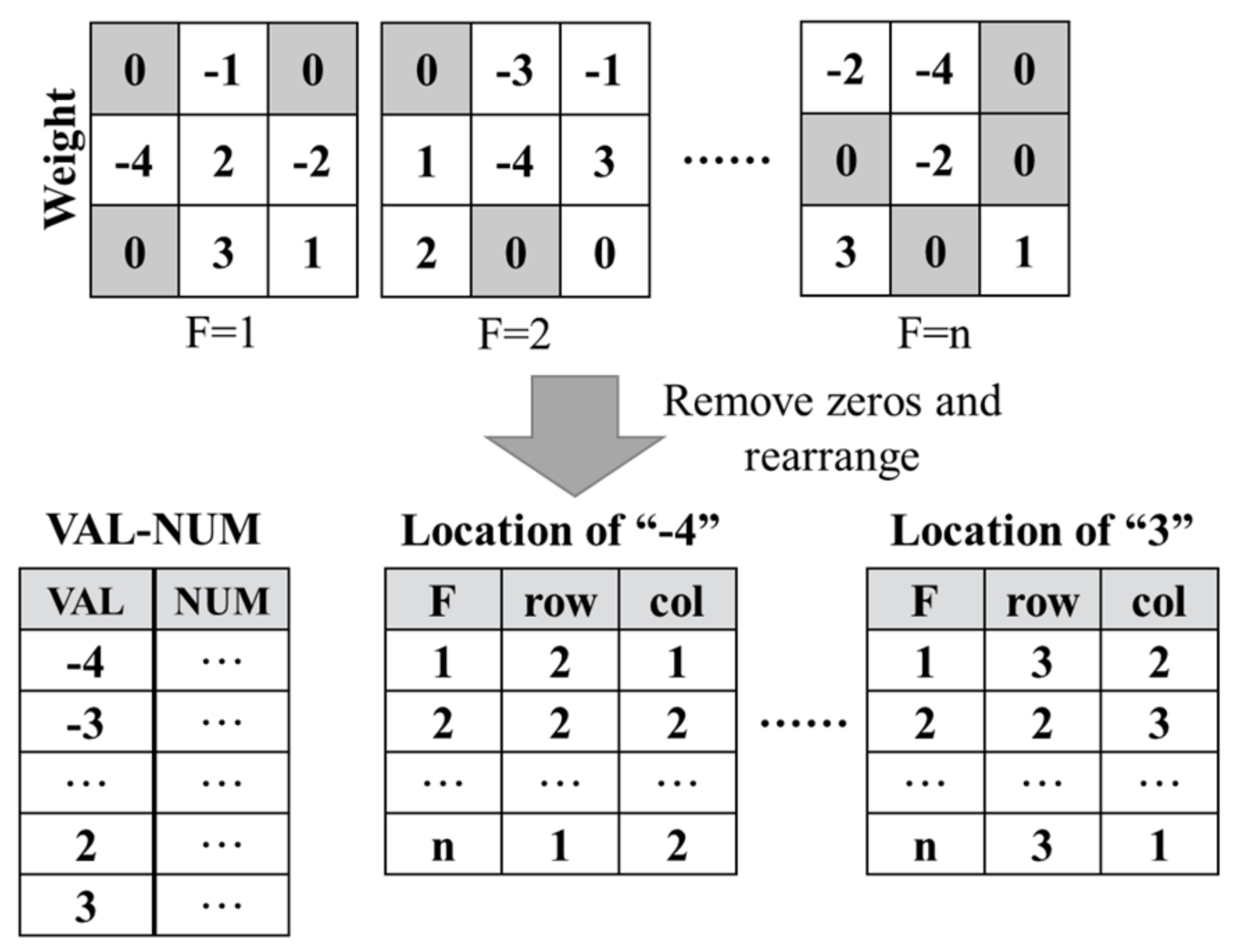
Another type of method focuses on reducing the use of multiplier units in the filter_loop through the optimized design of the hardware, such as ABM-SpConv [9,14,19], MF-Conv [13], and the weight-sharing (WS) technique [20,21,22]. The key to ABM-SpConv [9] is to perform the multiplication operations and accumulation operations of convolution in two separate stages. It finds and accumulates all the feature pixels with the same weights in the convolution kernel and produces partial products. Each partial product multiplies the corresponding weight and performs a final accumulation to obtain the output value. The intensity of the multiplications is reduced to the intensity of unique elements in the current convolution kernel. However, it is difficult to find the same elements in a small kernel, while small kernels are the trend. The authors of [14,19] have confirmed this issue. The authors expanded the scope of sharing the same weights into several kernels to implement ABM-SpConv, which increases the complexity of the hardware architecture. MF-Conv [13] avoids multiplication operations in convolution by using bit-resolution-based weight decomposition. In this way, the limitation of the DSP resources in terms of the parallelism of the convolution computation can be avoided with a simple hardware architecture. The key to MF-Conv is to decompose the weights to replace the multiplication operations via adding operations and shifting operations. MF-Conv has advantages in small convolution kernels; thus, it can cooperate with the Winograd algorithm. It aims to reduce the CNN computation and access costs by sharing convolutional kernels. The weight-sharing (WS) technique [20,21,22] aims to group weights into buckets or clusters sharing the same value. It allows for a significant reduction in the CNN memory footprint by storing shared values in a dedicated codebook, in which the original weight values in the weight matrix are replaced by their corresponding indexes. This method can reduce the number of parameters and computations required for convolution. However, it is not able to directly reduce the number of multiplications required in single-layer computing; therefore, it cannot reduce the dependence on DSPs.
2.2. Motivation
First, when using the current multiplication reduction approaches to design CNN accelerators, there is still the situation that the utilization of on-chip logic resources is imbalanced. Compared with the traditional accelerators, the Winograd-based WRA [8] reduces the multiplication operations in the row_loop and col_loop, leading to the transformation of the design space and relaxing the pressure on the required DSP resources. However, Table 1 implies that the WRA still relies more on DSP resources than on logic resources. ABM-SpConv [9,14,19] and MF-Conv [13] focus on reducing the use of multiplier units in the filter_loop, as shown in Figure 1. ABM-SpConv uses weights to group the input data, and the data corresponding to the same weight enter the same DSP. By using weight sharing, the number of DSPs is reduced. In this way, the limitation of DSP resources on the parallelism of convolution computation can be avoided with the hardware architecture. The key to MF-Conv is to decompose the weights to replace the multiplication operations via adding operations and shifting operations. MF-Conv has advantages in small convolution kernels; thus, it can cooperate with the Winograd algorithm. Although LUT resources can be directly constituted into multiplier units, they consume more resources and power. Moreover, the longer critical path leads to the lower efficiency of the convolution operation. MF-Conv ameliorates these issues. This work aims to combine the two categories mentioned above, thereby merging the performance benefits of different methods.
Figure 1.
One method to reduce the use of multiplier units in the filter_loop.
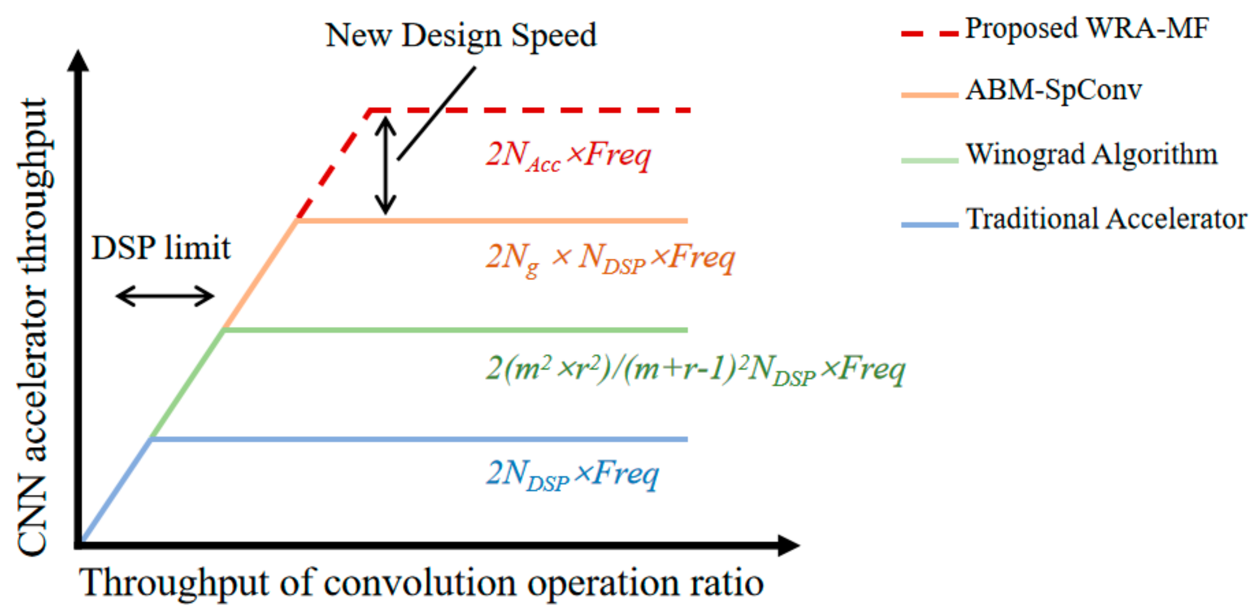
Second, the parallelism of convolution and the critical path of accelerators are limited by DSPs. Because the DSP is a fixed IP provided by the vendor, its critical path cannot be shortened further by modifying the design. If the DSP usage can be reduced or removed, this can increase the parallelism of the convolution operation and improve the convolution frequency. Assuming that the convolution operations have exhausted all the DSP resources, Figure 2 roughly estimates the computational roof of the aforementioned convolutional acceleration approach, where NDSP denotes the number of DSP blocks, and Freq denotes the clock frequency of the accelerators. denotes the input and output taps of the convolution operations for a Winograd-based accelerator. Ng denotes the number of elements that share the same DSP block in ABM-SpConv. Table 1 indicates that the Winograd algorithm and ABM-SpConv reduce the imbalance utilization between the logic and DSP blocks, but they do not eliminate the phenomenon completely. Therefore, the parallelism of the existing accelerated design is still limited by the number of DSP blocks, and the frequency is limited by the critical path of the DSP blocks. NAcc denotes the number of accumulators of the proposed WRA-MF. Because the proposed WRA-MF does not use DSPs, it can maximize the parallelism of the convolution operation. Furthermore, the frequency of the convolution operation is determined by the critical path of the accumulator. Through structural design, we can shorten the critical path of the accumulator through pipeline design to improve the convolution frequency.
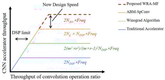
Figure 2.
Comparing several accelerators with proposed WRA-MF in roofline model.
Finally, CNN accelerators are generally the coprocessors of the entire system. If convolution operations exhaust all the DSP resources, then the whole functioning of the applications will not work. In real-world applications, such as surveillance systems [23] and autonomous vehicles [4], an inference accelerator is only part of the applications, as the applications have other functional units. The proposed WRA-MF can balance the utilization of the on-chip resources by reducing the number of DSPs used in the convolution, both to increase the parallelism and efficiency of the convolutional computation itself and to use DSPs for more scenarios in which the use of multiplication cannot be avoided, such as average pooling, processing units other than neural network accelerators, and so on. Once the unit is in place, more relaxed DSP resources can be used, enabling further improvements with other functions. This work can improve applications in two ways: it improves the parallelism of the convolution operations in inference, and it uses the released DSP resources to speed up the other functional units. Due to the relaxation of the design space for DSP resources, when all the function units are integrated into a single device with limited DSP blocks, the overall system performance can be greatly improved.
3. Approach
3.1. Preliminary
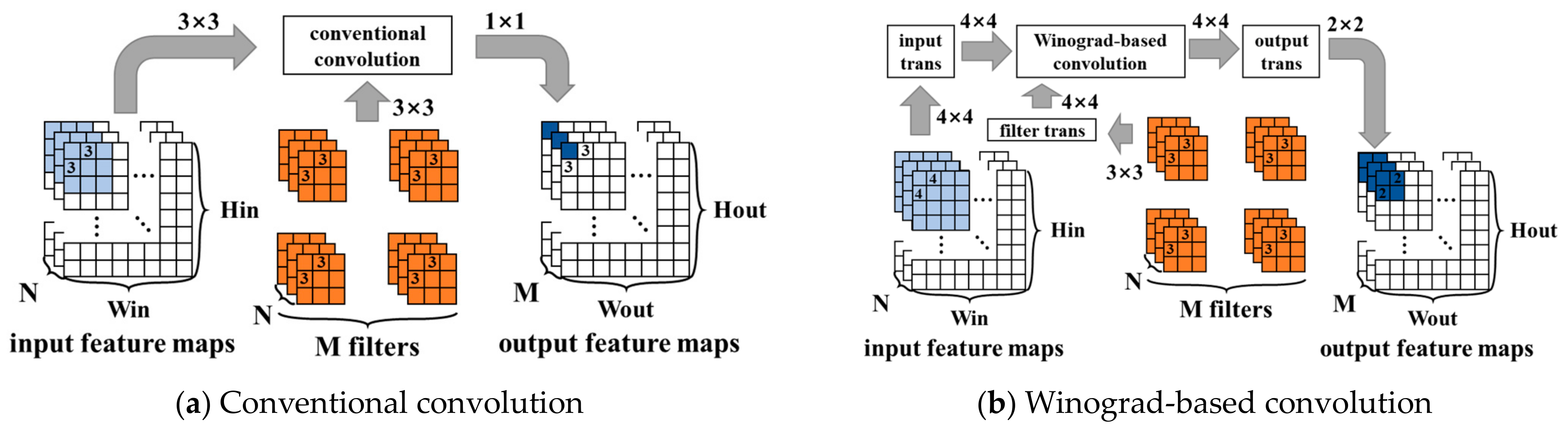
The Winograd algorithm is a fast convolution algorithm primarily used in deep learning, particularly in CNNs, to speed up the convolution operation. Figure 3 compares conventional convolution with Winograd-based convolution. Assuming there are input feature maps and output feature maps, the filters consist of groups, each group consisting of convolutional kernels. The Winograd algorithm transforms convolution operations into elementwise multiplication operations by transforming the input feature maps, filters, and output feature maps through fixed transformation matrices. The Winograd algorithm for computing outputs with an -tap FIR filter, which is called , has been known since at least 1980. By nesting the minimal 1-D Winograd and , the minimal 2-D Winograd algorithm for computing outputs with an filter can be realized, which is called . As the size increases, the three transform matrices become increasingly complex until the acceleration capability is lower than the transform cost. Generally, the most commonly used sizes are and . Larger sizes have too much transform overhead, and their constants are not , which is not conducive to hardware implementation.
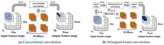
Figure 3.
Comparison of conventional convolution with Winograd-based convolution.
The hardware architecture of the convolution operation consists of a fixed form of a multiplier array and an adder array. Therefore, a convolution operation unit cannot be compatible with two or more operations of different sizes. For most CNN calculations, accelerators need multiple convolution operation units to match convolution kernels of different sizes; otherwise, the accelerators will not work. This study used a convolution computation architecture employing a stride-based convolution decomposition method (SCDM) [24] to make up for the shortage of MF-Conv, which makes the convolution unit more compatible. In the SCDM, kernels with different sizes are decomposed or filled to the shape of 3 × 3. Specifically, when the kernel size is less than 3, the kernel should be filled into 3 × 3 with zeros. When the kernel size is larger than 3 and the stride (s) is equal to 1, the kernel is decomposed into several 3 × 3 kernels. For example, a 5 × 5 kernel was decomposed into one 3 × 3 block, two 2 × 3 blocks, and one 2 × 2 block, as shown in Figure 4. The 2 × 3 block and 2 × 2 block were filled into 3 × 3 blocks via padding with zeros. When the stride (s) is equal to 1, it gathers neighboring elements into a decomposed kernel. When the stride (s) is equal to 2, instead of gathering neighboring elements into a decomposed kernel, the elements with two step distances both in the vertical and horizontal directions are gathered. When s = n, the elements with distances of n steps in both the vertical and horizontal directions are gathered together. Thus, the proposed convolution unit not only improves the underutilized logic resources but also normalizes the convolution operations. Therefore, the unified Winograd algorithm of can be used to achieve convolution operations with different kernel sizes and strides (s).
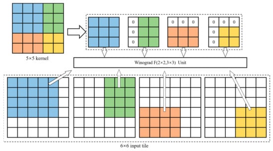
Figure 4.
Decomposition method for 5 × 5 kernel.
3.2. Method
In this section, we introduce the WRA-MF convolutional acceleration approach, a bit-level convolutional-weight-decomposition approach based on the Winograd algorithm. The key idea is to find the MAC operations in the Winograd algorithm and decompose the transformed weight so that the multiplication operations can be eliminated by transforming them into addition operations. Furthermore, by extracting common factors, the complexity of the addition operations is reduced.
The mode of convolution operations is the multiplication and accumulation operations between the input feature map and the kernel in the convolution window. Consider channels of the kernel, which has a total of such kernels, and channels of input feature maps. Each kernel performs convolution with a stride of s and generates the output feature map ():
where the element of the -th channel in the -th convolution kernel is and the input pixel of the -th channel in the -th convolution operations is .
In the row_loop and col_loop, the trajectory of the convolution operations is regular. The Winograd algorithm is based on this regularity. Consider the 1-D Winograd algorithm for computing m outputs using an tap filter () given below:
where denotes elementwise multiplication, denotes the input data, and denotes the filter coefficients. , , and are the input, filter, and output transform matrices, respectively.
Considering the filters sliding in the row_loop and col_loop, we nested Equation (2) as Equation (3), which is the 2-D Winograd algorithm in matrix form. Tile sizes are typically represented as , which denotes that the output is computed using an tap filter:
According to the characteristics of the hardware calculation, the computation of the weight matrix () and input matrix () can be preprocessed. We defined as the transformed filter matrix:
and we defined as the transformed input pixel matrix:
Then, the output () can be written in matrix form as follows:
The key to on-chip convolution acceleration is to accelerate the MAC operations. According to Equation (6), the MAC operations are concentrated in the term of . To visually describe the proposed convolution acceleration method, two new symbols will be introduced to represent the key steps in MAC operations:
Thus, the Winograd algorithm can be written as follows:
Here, and have the fixed 4 × 4 format, and has the fixed 2 × 4 format. Assuming that the elements () in are quantized and kept in fixed-point format with Q-bit precision, as shown in Equation (9), the can be decomposed into several pairs of summations of , and = 0, 1, 2…(Q − 1). We use the to decompose the exactly; here, the has only 0 and 1 values:
where the element in the transformed filter matrix is represented as . Then, can be written as follows:
Through the SCDM, the convolution kernel was decomposed or filled into the 3 × 3 format. Therefore, the tile size we used was . For the Winograd algorithm , the transformation matrix () of the input pixels is as follows:
The transformation matrix () of the filter is as follows:
The transformation matrix () of the output is as follows:
With the bit-level weight decomposition approach, we obtain the common factor , which is extracted, and the calculation of the elements in matrix () is simplified. Each element in is the sum of three elements in . The elements in matrix () are as follows:
The elements in matrix () are as follows:
Based on these new equations, we propose conducting the convolution computation in a three-stage flow, as follows:
- (1)
- Each filter matrix and input pixel matrix is transformed, obtaining () and (), respectively;
- (2)
- The transformed matrix () is decomposed at the bit level so that the multiplication operations can be replaced by accumulation operations and shift operations;
- (3)
- The output transformation matrix is used to transform matrix (), obtained in the second step, and, finally, the convolution result () is obtained.
- (4)
- Steps (1)~(3) are iteratively performed, and then output feature maps of all the convolution channels can be generated.
4. Implementation
4.1. WRA-MF Architecture
Figure 5 shows the overview of the convolution scheme of the proposed WRA-MF, including the computation module of , the input transformation matrix unit, the filter transformation matrix unit, and the output transformation matrix unit, which completes the calculation task of Equation (8). PATH1.1 and PATH1.2 read the data from the input buffer and filter buffer and then transform the data in the transformation matrix unit to obtain the transformed input pixel (V) and the transformed weight (U), respectively. Based on the Winograd algorithm, PATH1.1 and PATH1.2 simultaneously start and send data (V and U) to the computation module. The computation module contains eight MF-PEs, which calculate the elements in matrix (). These elements are sent to the output transformation unit to obtain the output element in matrix (). The input transformation unit and the filter transformation unit can accomplish the computation by sharing transformation logic [24], thereby involving little hardware overhead.
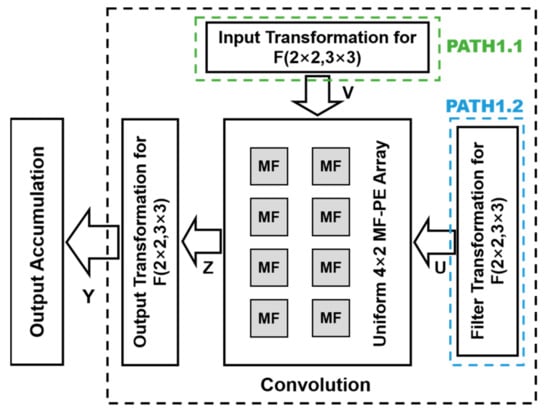
Figure 5.
Overview of architecture of WRA-MF convolution scheme.
4.2. Transform Units
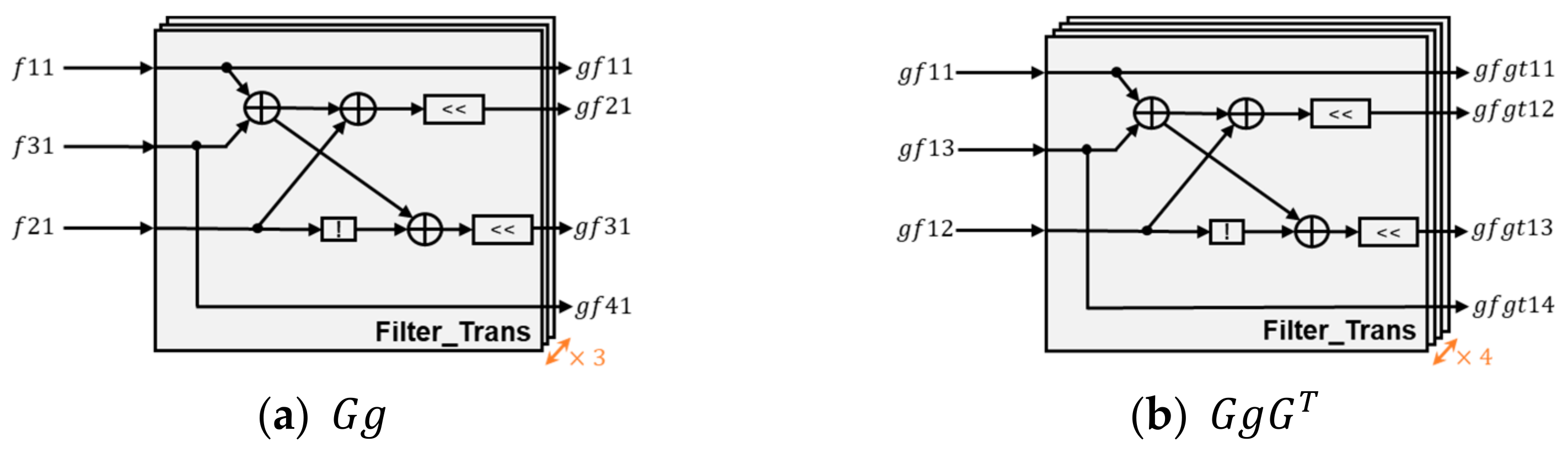
The filter transform unit is composed of 3 + 4 Filter_Trans arrays. The filter transformation architecture of the Filter_Trans arrays is shown in Figure 6. Each Filter_Trans array contains three addition operations, two shift operations, and one negation operation. The symbol is used to represent the elements of the filter matrix (). The calculation process of this transform unit includes the following two steps. First, it uses three Filter_Trans arrays to calculate the multiplication of matrix () and matrix () (i.e., in Equation (3)), which generates the intermediate result of the conversion module, as shown in Figure 6a. Then, the matrix () is obtained by using four Filter_Trans arrays to calculate the intermediate result and matrix () multiplication, as shown in Figure 6b.
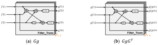
Figure 6.
filter transformation architecture.
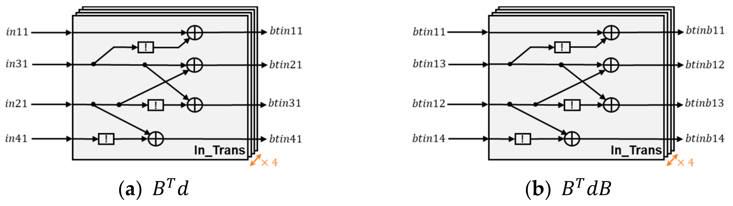
The input transform unit is composed of 4 + 4 In_Trans arrays. The input transformation architecture of the In_Trans arrays is shown in Figure 7. Each In_Trans array contains four addition operations and two negation operations.
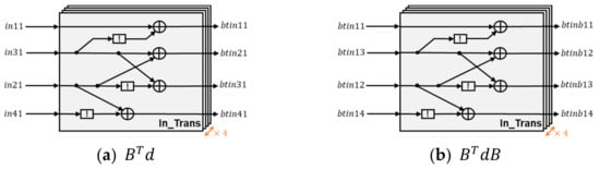
Figure 7.
input transformation architecture.
The output transform unit is composed of 4 + 2 Out_Trans arrays. The output transformation architecture of the Out_Trans arrays is shown in Figure 8. Each Out_Trans array contains four addition operations and two negation operations. The processes of the latter two transformations are similar to that of the first one.
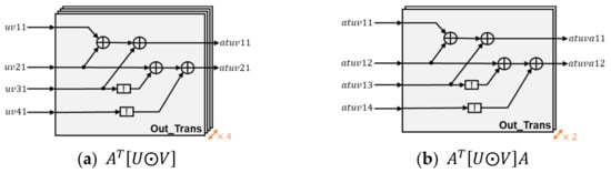
Figure 8.
output transformation architecture.
4.3. MF-PE
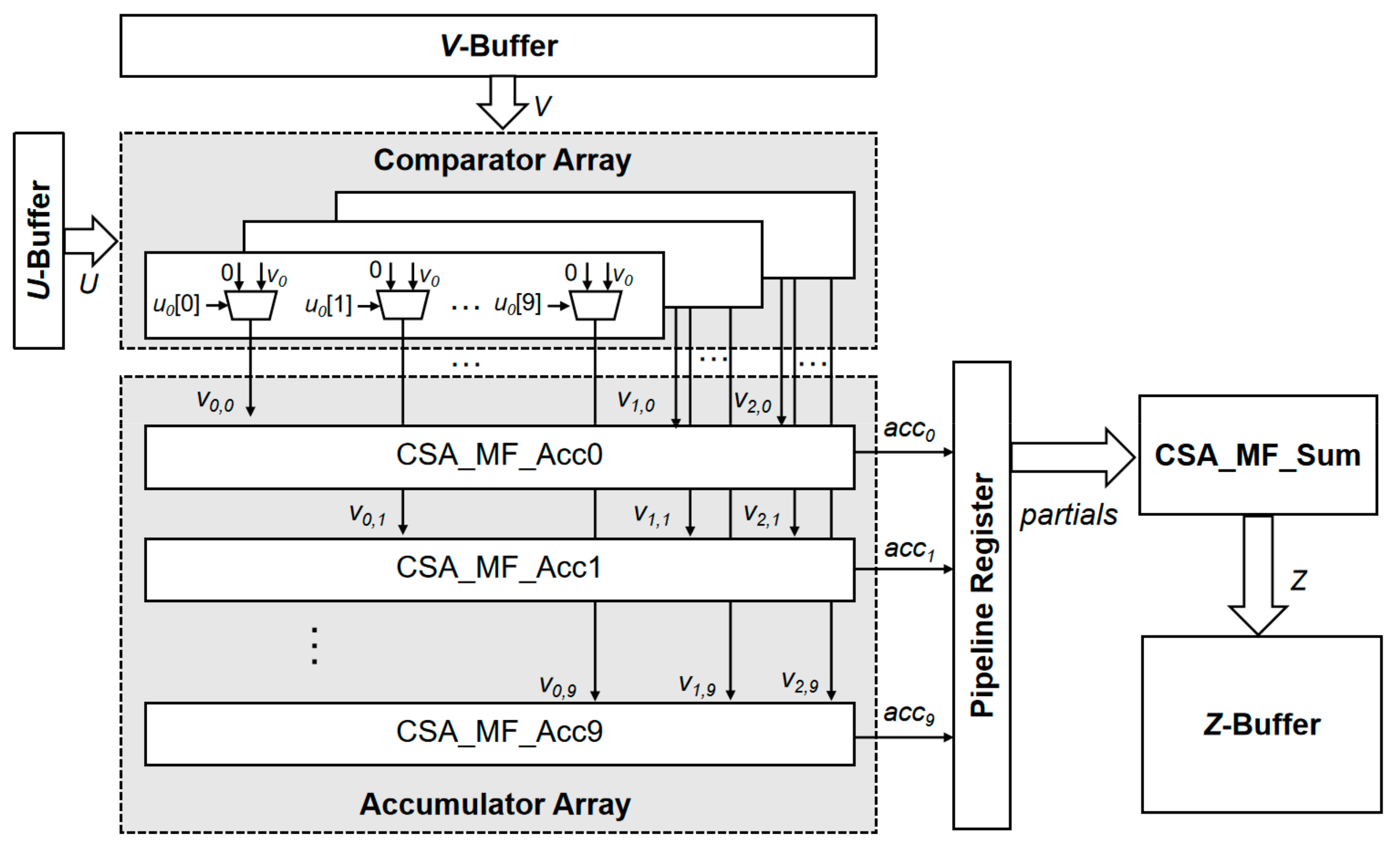
Figure 9 shows the architecture of the MF-PE for the proposed accelerator, including the comparator array, the accumulator array, the pipeline register, and the summation logic block CSA_MF_Sum. The authors of [25] have shown that the weight can be quantized with eight-bit precision and the inference accuracy decreases by less than 1%. Thus, accelerators operate with an eight-bit quantization weight for efficient design. The proposed accelerator transforms the convolution kernel via the Winograd algorithm, and this implies that our scheme requires a scheme with a 10-bit quantization (). From Equations (14)–(21), each operation includes three MAC operations. Thus, we designed three comparator arrays to traverse every bit of the elements in the . The comparator array labels the according to the and sends to the accumulator array. The pipeline register moves the accumulation result (Acc) to the left, and the amount of movement is the same as the value of the label. The pipeline register divides the operation into two stages, which ensures the effective pipelining of the MF-PE. Finally, the data obtained after the shift operation are accumulated, and the output () is obtained.
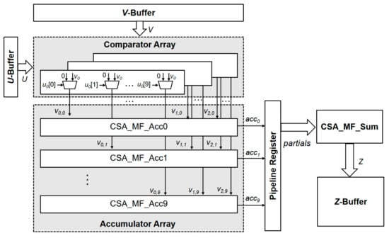
Figure 9.
Architecture of MF-PE.
4.4. Comparator Array
An MF-PE contains three comparator arrays, each with an input (u) element. A comparator array contains ten one-bit comparators to judge whether each bit of the element has a value of 1. Through the comparator, the determines whether the can be transmitted to the accumulator array. If the current bit of the is 0, then no action is taken. If the current bit of the is 1, then the position of the comparator is used as the label, and then the corresponding is assigned to and sent to the accumulator corresponding to the label. The function of a comparator array is shown in the pseudo-code of Table 3.
Table 3.
Pseudo-code of comparator array.
4.5. Carry-Save Adder (CSA)
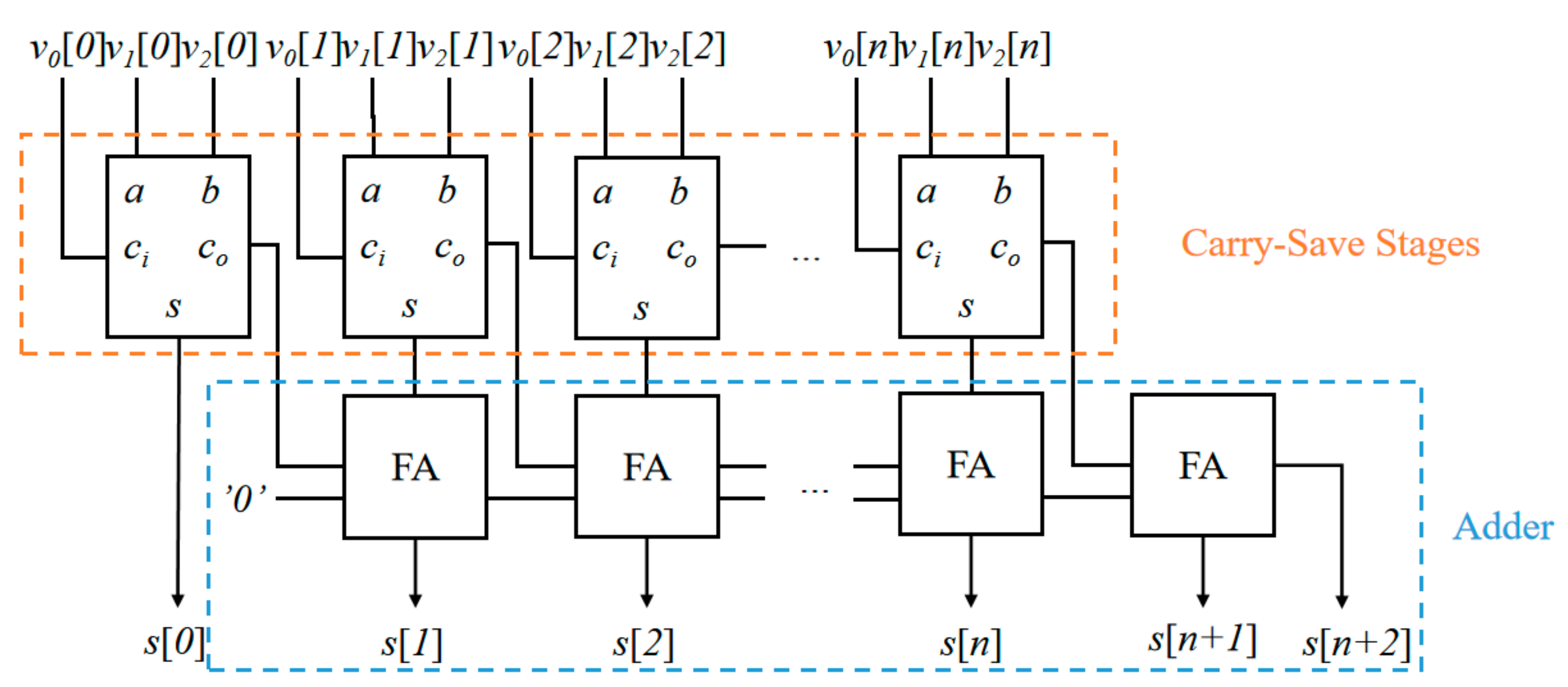
The MF-PE unit performs the accumulation of several elements, which determines the path delay convolution operations. The accumulator in the MF-PE performs the addition operation of three elements. The carry-save adder (CSA) has a minimal carry propagation delay when it performs the addition of several elements. The key to the CSA is to calculate and save the carry () and sum (s) separately, as shown in Equations (26) and (28):
The overall architecture of the accumulator and the CSA_MF_Sum in the MF-PE is shown in Figure 10. Suppose that three -bit numbers (, , ) are added. Here, is the -th bit of the -th element participating in the calculation. Because the input signals are computed in parallel, the delay of this architecture is approximately equal to the delay of two FA elements.
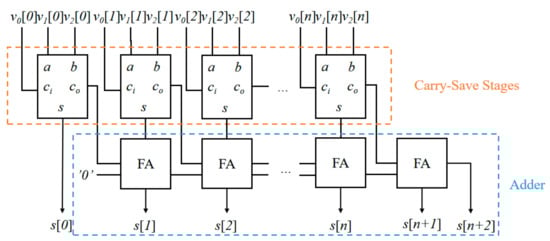
Figure 10.
Architecture of accumulator in MF-PE.
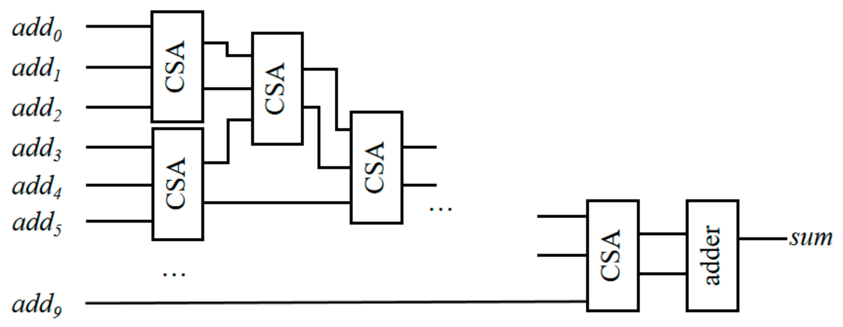
The sum function unit in the MF-PE performs the addition operations of ten elements. Figure 11 shows the overall architecture of the sum function unit, which contains multi-level CSA units. A CSA unit represents a carry-save stage. Here, is the -th element participating in the calculation.
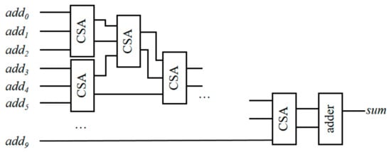
Figure 11.
Architecture of sum function in MF-PE.
5. Experimental Evaluation
5.1. Evaluation of Operations
The numbers of addition and multiplication operations required by the conventional convolution approach, ABM-SpConv [14], WRA [8], and proposed WRA-MF are compared in Table 4. To compare fairly, the three CNNs chosen here are models without pruning. It should be noted that ABM-SpConv discards the weights of “0” when storing, while the other schemes have “0” operations with them. In the WRA and WRA-MF, the operations of the input/filter/output transformations in the Winograd algorithm are also included. Although CAS is rarely used in CNN accelerators, it cannot be regarded as a unique method for the WRA-MF. For a fair comparison, the sum function in the MF-PE is considered to be nine operations of addition.
Table 4.
Number of Ops required by several convolution schemes.
Compared with other competitors, the proposed WRA-MF approach can completely eliminate multiplication at the cost of an addition increment. Compared to the conventional approach, the WRA-MF replaces all the multiplication operations with 6.12×, 3.94×, and 1.71× addition operations in the three CNN models. When compared to the ABM-SpConv, the WRA-MF introduces 6.70×, 5.18×, and 2.60× addition operation increments for the three CNN models. The WRA-MF decomposes and fills the filters in LeNet and AlexNet to the shape of 3 × 3, using more addition as the cost; thus, the addition operations in VGG16 increase the least. Both the WRA and WRA-MF employ the stride-based convolution decomposition method (i.e., SCDM), which is compatible with various sizes of filters; however, the WRA-MF can further replace all of the other multiplication operations with 8.25× addition operations in the three models. Based on our implementation results, an eight-bit multiplier requires 8.88× more hardware resources than an adder with the same bit width. Therefore, the proposed WRA-MF approach is more effective in hardware design and at achieving DSP savings.
5.2. Results and Comparisons
The hierarchical structure of VGG16 is listed in Table 5, which contains convolution, max pooling, fully connected layers, and a softmax. The sizes of the convolutions are all 3 × 3/1, which is suitable for using the Winograd algorithm. Its pooling is all max pooling, which does not require complex calculations to achieve, only an additional dedicated module after the WRA-MF convolution scheme. Because the fully connected layers and softmax of Layer 19–Layer 22 have large differences in the degrees of regularity of the convolution and max-pooling computation with the first 18 layers, this part of the computation is not implemented in the WRA-MF architecture, but the results of the 18th layer are outputted to the software side for the final computation.
Table 5.
Hierarchical structure of VGG16.
The proposed WRA-MF was synthesized on the Xilinx XCVU9P FPGA with an eight-bit fixed-point data representation. The results of the WRA-MF are listed in Table 6, as well as performance comparisons with other accelerators. Compared with the conventional convolution approach [26,27], the area efficiency of this work has a 21.7×–27.55× improvement. This is because the proposed WRA-MF replaces all DSPs with logical resources, resulting in significant increases in the throughput and clock frequency. Compared with works on the sharing method [14,28], the proposed WRA-MF’s area efficiency has a 3.47×–5.63× improvement. These works can reduce the number of DSPs in the filter_loop so that, while improving the throughput, they do not consume excessive resources. However, it is difficult to find the same elements in a small kernel, while small kernels are the trend, which limits the applicability of this method. Compared to the works [8,29,30], which use the Winograd algorithm, this structure can improve the area efficiency by 5.57×, 10.14×, and 6.05×, respectively. The experimental platform Xilinx XCVU9P used by the WRA-MF is the same as in [8]. The platform has powerful DSP computing power that can ensure the high parallelism of the convolution operations in the WRA accelerator. Therefore, the platform is very expensive. With the WRA-WF, the accelerator can be transferred to other low-cost platforms while ensuring the parallelism of the convolution operations. In a word, the proposed WRA-MF has two main advantages. The first point is to eliminate the use of DSPs completely, at the cost of slightly increasing the logic cell. The second point is that, by decoupling the DSPs and convolutional operations, the WRA-MF shorts the critical path of the convolution operations and contributes to significantly promoting the throughput roofline of FPGA-based CNN accelerators. Compared with competitors, the proposed WRA-MF has improved clock frequency, throughput, and area efficiency.
Table 6.
Comparison with other designs.
6. Conclusions
This paper proposes a multiplication-free CNN acceleration unit (named WRA-MF) that fuses the Winograd algorithm and MF-Conv units, achieving complementary performance advantages. The proposed WRA-MF completely avoids the use of DSP blocks. The implementation on the Xilinx XCVU9P FPGA shows that it can run at a clock frequency of 509 MHz, performing 7559 GOP/s throughput. Compared with state-of-the-art works, the WRA-MF achieves up to a 3.47×–27.55× area efficiency improvement.
Author Contributions
Conceptualization, S.X., X.L. and C.Y.; methodology, S.X. and X.L.; software, S.X. and X.L.; validation, Y.M. and J.W.; investigation, S.X.; writing—original draft preparation, S.X. and X.L.; writing—review and editing, S.X. and C.L.; data curation, C.L.; visualization, X.L.; supervision, C.Y. and C.L.; project administration, C.Y.; funding acquisition, C.Y. All authors have read and agreed to the published version of the manuscript.
Funding
This research was funded in part by the National Natural Science Foundation of China under Grant 62176206, and in part by the Shenzhen Park of Hetao Shenzhen–Hong Kong Science and Technology Innovation Cooperation Zone Program under Grant HTHZQSWS-KCCYB-2023040.
Data Availability Statement
The data presented in this study are available on request from the corresponding author. The data are not publicly available due to privacy reason of our RTL design.
Conflicts of Interest
The author Cimang Lu was employed by the company Shenzhen Xinrai Sinovoice Technology. The remaining authors declare that the research was conducted in the absence of any commercial or financial relationships that could be construed as a potential conflict of interest.
References
- Wodzinski, M.; Skalski, A.; Hemmerling, D.; Orozco-Arroyave, J.R.; Nöth, E. Deep Learning Approach to Parkinson’s Disease Detection Using Voice Recordings and Convolutional Neural Network Dedicated to Image Classification. In Proceedings of the 2019 41st Annual International Conference of the IEEE Engineering in Medicine and Biology Society (EMBC), Berlin, Germany, 23–27 July 2019; pp. 717–720. [Google Scholar]
- He, K.; Zhang, X.; Ren, S.; Sun, J. Deep Residual Learning for Image Recognition. In Proceedings of the 2016 IEEE Conference on Computer Vision and Pattern Recognition (CVPR), Las Vegas, NV, USA, 27–30 June 2016; pp. 770–778. [Google Scholar]
- Girshick, R.; Donahue, J.; Darrell, T.; Malik, J. Rich Feature Hierarchies for Accurate Object Detection and Semantic Segmentation. In Proceedings of the 2014 IEEE Conference on Computer Vision and Pattern Recognition (CVPR), Columbus, OH, USA, 23–28 June 2014; pp. 580–587. [Google Scholar]
- Afdhal, A.; Nasaruddin, N.; Fuadi, Z.; Sugiarto, S.; Riza, H.; Saddami, K. Evaluation of Benchmarking Pre-Trained CNN Model for Autonomous Vehicles Object Detection in Mixed Traffic. In Proceedings of the 2022 International Conference on ICT for Smart Society (ICISS), Bandung, Indonesia, 10–11 August 2022; pp. 1–6. [Google Scholar]
- Yang, T.-J.; Chen, Y.-H.; Sze, V. Designing Energy-Efficient Convolutional Neural Networks Using Energy-Aware Pruning. In Proceedings of the 2017 IEEE Conference on Computer Vision and Pattern Recognition (CVPR), Honolulu, HI, USA, 21–26 July 2017; pp. 6071–6079. [Google Scholar]
- Suda, N.; Chandra, V.; Dasika, G.; Mohanty, A.; Ma, Y.; Vrudhula, S.; Seo, J.S.; Cao, Y. Throughput-optimized OpenCL-based FPGA accelerator for large-scale convolutional neural networks. In Proceedings of the 2016 ACM/SIGDA International Symposium on Field-Programmable Gate Arrays, Monterey, CA, USA, 21–23 February 2016; pp. 16–25. [Google Scholar]
- Zeng, H.; Chen, R.; Zhang, C.; Prasanna, V. A framework for generating high throughput CNN implementations on FPGAs. In Proceedings of the 2018 ACM/SIGDA International Symposium on Field-Programmable Gate Arrays, New York, NY, USA, 25–27 February 2018; pp. 117–126. [Google Scholar]
- Yang, C.; Wang, Y.; Wang, X.; Geng, L. WRA: A 2.2-to-6.3 TOPS Highly Unified Dynamically Reconfigurable Accelerator Using a Novel Winograd Decomposition Algorithm for Convolutional Neural Networks. IEEE Trans. Circuits Syst. I Regul. Pap. 2019, 66, 3480–3493. [Google Scholar] [CrossRef]
- Wang, D.; Xu, K.; Jia, Q.; Ghiasi, S. ABM-SpConv: A novel approach to FPGA-based acceleration of convolutional neural network inference. In Proceedings of the 56th Annual Design Automation Conference, Las Vegas, NV, USA, 2–6 July 2019; pp. 1–6. [Google Scholar]
- Yue, J.; Liu, R.; Sun, W.; Yuan, Z.; Wang, Z.; Tu, Y.N.; Chen, Y.-J.; Ren, A.; Wang, Y.; Chang, M.-F.; et al. 7.5 A 65nm 0.39-to-140.3TOPS/W 1-to-12b Unified Neural Network Processor Using Block-Circulant-Enabled Transpose-Domain Acceleration with 8.1 × Higher TOPS/mm2and 6T HBST-TRAM-Based 2D Data-Reuse Architecture. In Proceedings of the 2019 IEEE International Solid-State Circuits Conference (ISSCC), San Francisco, CA, USA, 17–21 February 2019; pp. 138–140. [Google Scholar]
- Wang, J.; Lin, J.; Wang, Z. Efficient Hardware Architectures for Deep Convolutional Neural Network. IEEE Trans. Circuits Syst. I Regul. Pap. 2018, 65, 1941–1953. [Google Scholar] [CrossRef]
- Lavin, A.; Gray, S. Fast Algorithms for Convolutional Neural Networks. In Proceedings of the 2016 IEEE Conference on Computer Vision and Pattern Recognition (CVPR), Las Vegas, NV, USA, 27–30 June 2016; pp. 4013–4021. [Google Scholar]
- Yang, C.; Lv, X.; Li, B.; Fan, S.; Mei, K.; Geng, L. MF-Conv: A Novel Convolutional Approach Using Bit-Resolution-based Weight Decomposition to Eliminate Multiplications for CNN Acceleration. In Proceedings of the 2020 IEEE 15th International Conference on Solid-State & Integrated Circuit Technology (ICSICT), Kunming, China, 3–6 November 2020; pp. 1–3. [Google Scholar]
- Wang, D.; Xu, K.; Guo, J.; Ghiasi, S. DSP-Efficient Hardware Acceleration of Convolutional Neural Network Inference on FPGAs. IEEE Trans. Comput.-Aided Des. Integr. Circuits Syst. 2020, 39, 4867–4880. [Google Scholar] [CrossRef]
- Wang, X.; Wang, C.; Cao, J.; Gong, L.; Zhou, X. WinoNN: Optimizing FPGA-Based Convolutional Neural Network Accelerators Using Sparse Winograd Algorithm. IEEE Trans. Comput.-Aided Des. Integr. Circuits Syst. 2020, 39, 4290–4302. [Google Scholar] [CrossRef]
- Yepez, J.; Ko, S.-B. Stride 2 1-D, 2-D, and 3-D Winograd for Convolutional Neural Networks. IEEE Trans. Very Large Scale Integr. (VLSI) Syst. 2020, 28, 853–863. [Google Scholar] [CrossRef]
- Abtahi, T.; Shea, C.; Kulkarni, A.; Mohsenin, T. Accelerating Convolutional Neural Network With FFT on Embedded Hardware. IEEE Trans. Very Large Scale Integr. (VLSI) Syst. 2018, 26, 1737–1749. [Google Scholar] [CrossRef]
- Wang, H.; Xu, W.; Zhang, Z.; You, X.; Zhang, C. An Efficient Stochastic Convolution Architecture Based on Fast FIR Algorithm. IEEE Trans. Circuits Syst. II Express Briefs 2022, 69, 984–988. [Google Scholar] [CrossRef]
- Li, X.; Gong, X.; Wang, D.; Zhang, J.; Baker, T.; Zhou, J.; Lu, T. ABM-SpConv-SIMD: Accelerating Convolutional Neural Network Inference for Industrial IoT Applications on Edge Devices. IEEE Trans. Netw. Sci. Eng. 2023, 10, 3071–3085. [Google Scholar] [CrossRef]
- Dupuis, E.; Novo, D.; O’Connor, I.; Bosio, A. A Heuristic Exploration of Retraining-free Weight-Sharing for CNN Compression. In Proceedings of the 2022 27th Asia and South Pacific Design Automation Conference (ASP-DAC), Taipei, Taiwan, 17–20 January 2022; pp. 134–139. [Google Scholar]
- Liu, Y.; Zhao, B.; Zhang, S.; Xiao, W. Motor Imagery EEG Recognition Based on Weight-Sharing CNN-LSTM Network. In Proceedings of the 2022 34th Chinese Control and Decision Conference (CCDC), Hefei, China, 15–17 August 2022; pp. 1382–1386. [Google Scholar]
- Takahashi, R.; Matsubara, T.; Uehara, K. A Novel Weight-Shared Multi-Stage CNN for Scale Robustness. IEEE Trans. Circuits Syst. Video Technol. 2019, 29, 1090–1101. [Google Scholar] [CrossRef]
- Cameron, J.A.D. Design considerations for the processing system of a CNN-based automated surveillance system. Expert Syst. Appl. 2019, 136, 105–114. [Google Scholar] [CrossRef]
- Yang, C.; Wang, Y.; Wang, X.; Geng, L. A Stride-Based Convolution Decomposition Method to Stretch CNN Acceleration Algorithms for Efficient and Flexible Hardware Implementation. IEEE Trans. Circuits Syst. I Regul. Pap. 2020, 67, 3007–3020. [Google Scholar] [CrossRef]
- Gysel, P.; Pimentel, J.; Motamedi, M.; Ghiasi, S. Ristretto: A Framework for Empirical Study of Resource-Efficient Inference in Convolutional Neural Networks. IEEE Trans. Neural Netw. Learn. Syst. 2018, 29, 5784–5789. [Google Scholar] [CrossRef] [PubMed]
- Lu, J.; Ni, C.; Wang, Z. ETA: An Efficient Training Accelerator for DNNs Based on Hardware-Algorithm Co-Optimization. IEEE Trans. Neural Netw. Learn. Syst. 2022, 34, 7660–7674. [Google Scholar] [CrossRef] [PubMed]
- Huang, W.; Wu, H.; Chen, Q.; Luo, C.; Zeng, S.; Li, T.; Huang, Y. FPGA-Based High-Throughput CNN Hardware Accelerator With High Computing Resource Utilization Ratio. IEEE Trans. Neural Netw. Learn. Syst. 2022, 33, 4069–4083. [Google Scholar] [CrossRef] [PubMed]
- Yin, Q.; Li, Y.; Huang, H.; Li, H.; Zhang, Q.; Cao, B.; Zhang, J. FPGA-based High-performance CNN Accelerator Architecture with High DSP Utilization and Efficient Scheduling Mode. In Proceedings of the 2020 International Conference on High Performance Big Data and Intelligent Systems (HPBD&IS), Shenzhen, China, 23–23 May 2020; pp. 1–7. [Google Scholar]
- Li, S.; Wang, Q.; Jiang, J.; Sheng, W.; Jing, N.; Mao, Z. An Efficient CNN Accelerator Using Inter-Frame Data Reuse of Videos on FPGAs. IEEE Trans. Very Large Scale Integr. (VLSI) Syst. 2022, 30, 1587–1600. [Google Scholar] [CrossRef]
- Liu, X.; Chen, Y.; Hao, C.; Dhar, A.; Chen, D. WinoCNN: Kernel Sharing Winograd Systolic Array for Efficient Convolutional Neural Network Acceleration on FPGAs. In Proceedings of the 2021 IEEE 32nd International Conference on Application-specific Systems, Architectures and Processors (ASAP), Piscataway, NJ, USA, 7–9 July 2021; pp. 258–265. [Google Scholar]
- Chen, J.; Zhang, Z.; Lu, H.; Hu, J.; Sobelman, G.E. An Intra-Iterative Interference Cancellation Detector for Large-Scale MIMO Communications Based on Convex Optimization. IEEE Trans. Circuits Syst. I Regul. Pap. 2016, 63, 2062–2072. [Google Scholar] [CrossRef]
- Wang, W.-C.; Hung, Y.-C.; Du, Y.-H.; Yang, S.-H.; Huang, Y.-H. FPGA-Based Tensor Compressive Sensing Reconstruction Processor for Terahertz Single-Pixel Imaging Systems. IEEE Open J. Circuits Syst. 2022, 3, 336–350. [Google Scholar] [CrossRef]
- Ho, P.-P.; Chen, C.-E.; Huang, Y.-H. Low-Latency Lattice-Reduction-Aided One-Bit Precoding Processor for 64-QAM 4×64 MU–MIMO Systems. IEEE Open J. Circuits Syst. 2021, 2, 472–484. [Google Scholar] [CrossRef]
- Tu, J.; Lou, M.; Jiang, J.; Shu, D.; He, G. An Efficient Massive MIMO Detector Based on Second-Order Richardson Iteration: From Algorithm to Flexible Architecture. IEEE Trans. Circuits Syst. I Regul. Pap. 2020, 67, 4015–4028. [Google Scholar] [CrossRef]


Disclaimer/Publisher’s Note: The statements, opinions and data contained in all publications are solely those of the individual author(s) and contributor(s) and not of MDPI and/or the editor(s). MDPI and/or the editor(s) disclaim responsibility for any injury to people or property resulting from any ideas, methods, instructions or products referred to in the content. |
© 2023 by the authors. Licensee MDPI, Basel, Switzerland. This article is an open access article distributed under the terms and conditions of the Creative Commons Attribution (CC BY) license (https://creativecommons.org/licenses/by/4.0/).