Abstract
Low-power wide-area (LPWA) technologies have gained popularity in accordance with the explosive growth of the Internet of Things (IoT). Among others, LoRa is considered as the leading standard that can meet the needs of modern wireless networking, mainly offering energy efficiency and broad coverage as well as a massive amount of device support. In addition to the ALOHA protocol, which is the default channel access mechanism used by the standard, a number of alternatives have been proposed in the literature in an effort to ameliorate the overall network performance. Furthermore, with moving nodes gaining ground more and more in the IoT realm and the research being at a relatively premature stage, it is imperative to create innovative algorithms that support highly dense networks with fast moving nodes. Motivated by these reasons, this work proposes a novel medium access protocol that takes advantage of the increased capabilities of modern wake up radio (WuR) technology in order to achieve low latency and mitigate the risk of lost packets in IoT networks with moving nodes based on the LoRa technology. A number of simulation scenarios have been devised and the findings suggest that the proposed protocol achieves the set goals and improves existing solutions.
1. Introduction
As the Internet of Things (IoT) continues to pave the way for innovations in network technologies, there are a number of network options on which to build smart applications for a variety of everyday life sectors. Being the major communication paradigm in this area, LoRa technology seems to fit perfectly with the IoT philosophy. Being part of the low-power wide-area network (LPWAN) technology, which provides low-cost, low-power, and wide-area coverage, needed for the ongoing era of ubiquitous computing, LoRa adds also the ease of applicability and expandability, maintaining its position among the most popular communication technologies applied for the IoT cosmos.
Geared for IoT low traffic applications where small amounts of data are transmitted periodically, LPWAN redefines the way applications and processes are developed and established. In addition, supporting this LPWAN approach, a number of appropriate communication standards, based on the energy needs of these networks, have already achieved a level of penetration in IoT applications like city lighting, parking, utilities metering and other agriculture and industry specific uses. Among these LPWAN technologies, such as Sigfox, LoRa, NB-IoT, LTE-M, Wi-Sun, and others, LoRa has gained large popularity due to the fact that it operates in an unlicensed spectrum band, offers low deployment and operation costs without the need of a third party, and is based on a simple star topology with gateways suited for simple control and routing schemes. Apart from the aforementioned leverages, LoRa also offers high adaptability to different applications as it is highly flexible concerning the operational parameters like the SF- Spreading Factor, the coding rate, the bandwidth, the payload length and the preamble length. Configuring those parameters according to each application, one can balance between higher throughput or increased range achieving also different battery-life times.The sweet spot between these factors is crucial for the successful operation of the network and are application-specific.
While in an increased number of applications, the nodes are considered stationary, moving-related applications have started to attract more and more attention. As configuration methods of optimal settings in LoRa wide-area network (LoRaWAN) specification are only present for slowly moving or stationary end nodes [1], moving nodes demand novel evaluation. While there are a number of works involving moving nodes (presented below) the majority use the same fixed high energy settings throughout the movement in order to achieve high reliability.
Motivated by the aforementioned parameter diversity and the lack of adaptive protocols for moving nodes with LoRa technology, in this work we propose a novel way to optimize performance and reliability in highly dense networks with fast moving nodes. The proposed algorithm acts proactively and reserves an additional slot in the higher SF region for every active scheduled transmission in a way to eliminate the possibility of a lost packet. Due to the moving nature of the nodes, there should be a kind of orchestration for the different SF zones they constantly visit. Acting as a point of segregation from the typical single-node-supervision algorithms, the proposed communication protocol enables all the nodes to take part in a decentralized way.
The reminder of this article is organized as follows. In Section 2 background and related work is presented. The proposed algorithm along with the system configuration setup are presented in Section 3. Section 4 includes the evaluation of the results along with the performance analysis and in the Section 5 we conclude this work.
2. Related Work
According to [1], the default channel access mechanism is the pure ALOHA technique, a random access protocol where data is transmitted randomly from various end devices across a single channel in accordance with their communication requirements. Its lightweight nature as well as its simplicity and the absence of synchronization between the devices renders it quite suitable for sensor networks with low-traffic applications. The behavior of ALOHA-based protocol in terms of reliability, network latency, throughput, and energy efficiency has come under scrutiny from researchers who argue that it suffers from low scalability while at the same time its performance significantly deteriorates in cases of heavy traffic as the number of network devices increases [2,3,4,5]. In order to improve the abovementioned metrics, several extensions or modifications to the LoRaWAN MAC layer protocol have been proposed in the literature. Slotted ALOHA, introduced as an improvement over ALOHA protocol, allows the data transmission from each station only at the beginning of the time slot, achieving better performance metrics as it doubles the capacity of the wireless channel compared to pure-ALOHA. In [2], Polinelli et al. concluded that by using the slotted ALOHA protocol over LoRaWAN, instead of the ALOHA approach, a 5.8× increase in network throughput and a 26% reduction of packet collisions is obtained in high-traffic load conditions.
In addition to the random access protocols which are generally used in LoRaWANs, channelization protocols are also of particular interest. Time-division multiple access (TDMA) is a collision free protocol which provides multiple access to end devices by dividing the available bandwidth in time. In [6,7], Piyare et al. proposed a receiver-initiated version of the aforementioned protocol which was tested and evaluated using a real deployment of eleven wireless sensor nodes. Ultra-low-power wake-up-radios which offer continuous listening of the wireless communication mean that extremely low power-consumption is introduced in this work to boost the overall network performance.The suggested approach was compared to the listen before talk (LBT) protocol in terms of network reliability, latency, and energy efficiency, achieving superior performance. In [8], the authors suggested an enhanced version of [6], also employing the WURs’ low-power capacities. More precisely, using the TDMA principles, this work composes a lightweight form of prediction in an effort to prevent an end device that has no information to relay to reserve a whole timeslot in the current transmission cycle. This way notable outcomes in terms of mean data latency and times of node polling are brought about. Spathi et al. in [9], proposes an AI-based TDMA mechanism in an effort to extend the network’s longevity by balancing the energy consumption of the network devices. In detail, a learning automaton tool is used in order to determine, depending on the residual battery of each device, which one of the available end nodes would serve as a cluster head during the next cycle of the TDMA. The suggested mechanism attains improvements in terms of network’s lifespan of up to 1.4× and 6.7× when compared to the round-robin and static TDMA approaches, respectively.
While the transmission settings play a pivotal role in the performance of a LoRa network, as they affect the energy consumption, the data rate, and the coverage area, the optimal configuration should be a continuous process in case of the presence of moving nodes. That being said, in [10] the authors proposed a dynamic selection of optimal transmission settings based on estimated path loss of each node and the nearest gateway. The authors in [11] proposed an energy-efficient mechanism for LoRa networks based on the node’s state battery; in order to save most of the energy consumed, they base the node localization on trilateration and time difference of arrival as the most common solution of a GPS could jeopardize the energy efficiency in search and rescue operations. For another form or moving nodes, the UAV, the authors in [12] proposed a distributed topology control algorithm based on the link budget between nodes and movement prediction techniques in a network formation where the nodes communicate via LoRa messages with the UAV nodes and the latter communicate over WiFi with the base station to propagate the messages to the backbone. Similar to the aforementioned work, in [13] the authors tested a node-to-UAV LoRa mesh network by applying a slotted ALOHA approach offering a robustness to network dynamic topology.
In the next works, the use of LoRa in conjunction with moving nodes is presented in an effort to show the wide applicability of this technology. The authors of [14] designed and implemented a bicycle location-tracking system as a proof of concept for the use of low-power and wide-area network technology for IoT under various network formations. Similarly, in the work of [15] the authors tested the achievable transmission distance in an urban area using this time cars instead of bicycles. Again, in another use of LoRaWAN with moving nodes [16], the authors used moving LoRa nodes to monitor another flavor of the IoT, using floating solar panels. The authors in [17] propose the use of a LoRa transmitter via mobile phones for the dissemination of an emergency message in cases where the cellular network is inoperative. Under the proposed operation protocol, the nodes can operate as delay-tolerant transmitters depending either on timer expiration or the reception of different message types.
It should be mentioned that the proposed algorithm is unique as it is tested in dense environments and offers different characteristics from the previous works with moving nodes. It considers a two way communication as distinct from [10] which does not take into account the response from the base station. The authors in [11] test up to 500 nodes and consider ultra-low speed nodes that do not change their spreading factor as the proposed protocol. The same applies also for [12], where the authors do not consider changes in the SF of the ground nodes as the data are transmitted to the base station through UAV nodes via WiFi ad hoc network. This protocol, along with the [13], have many common components with the proposed one but we utilize only LoRa technology for the actual data transmission and do not relay on other technologies (the use of WuR is only for orchestration and energy-saving purposes). The dense network formations tested in this work are not present in the other works that lack such escalation.
Prompted from the above consideration of a delay-tolerant network in conjunction with the connectivity issues that may arise in networks with moving nodes, we present also some works that have considered IoT with the notion of opportunistic networking. In [18] the authors propose the use of opportunistic fog computing in hazardous and volatile situations where resources and connectivity are inherently limited. One emerging field of application for this type of fog architecture is the flying IoT and drones sector. The fog devices are referred to mainly as vehicle and mobile phone nodes.Along the same lines, in [19] the authors study the performance of the opportunistic fog network for offloading computing tasks from the IoT network. In [20], the authors propose the use of opportunistic networks nodes and their computing features as a way of sampling of data and elaboration by involving other users in a distributed fashion without intervening in a central processing node.
3. Algorithm Description
3.1. System Configuration
In this section, we are going to describe the architecture of the whole system, the parts of the system and how these parts are connected. Figure 1 illustrates the network architecture adopted in this work. In detail, the network encompasses three different kinds of devices: the sink node (SN), the cluster head, (CH) and the end device (ED), modeling a cluster with a variable number of EDs. Pertaining to the position-placing of the employed nodes, the SN is always located in any place on the outer cycle, the CH is placed on the center of the inner cycle, while the moving EDs can be positioned anywhere inside the outer cycle. The circular sectors depicted with dashed lines at the top of Figure 1 constitute the boundaries between the different SF zones (7–12) defined by LoRaWAN. Therefore, each ED depending on the distance it has from the SN sends its LoRa message using the appropriate SF as part of the inherent ADR mechanism. The CH, which is responsible for orchestrating communication between the EDs and the SN, and the EDs are both equipped with a LoRa transceiver as well as a WuR transceiver, allowing pure asynchronous operation. More precisely, the system is able to support bidirectional communication between the CH and the EDs through the WuR equipment, allowing both types of devices to trigger each other via wake up beacon messages (WuB), while simultaneously assuring energy efficiency as the EDs enable their main LoRa radio on demand only, avoiding continuous transmissions.In addition, the EDs can realize single-hop unidirectional transmissions with the SN using their LoRa transceivers. The SN, on the other hand, is equipped only with a LoRa transceiver permitting long-range bidirectional transmissions with the CH in order to directly gather data from the latter as well as the EDs and to update the network’s parameters.
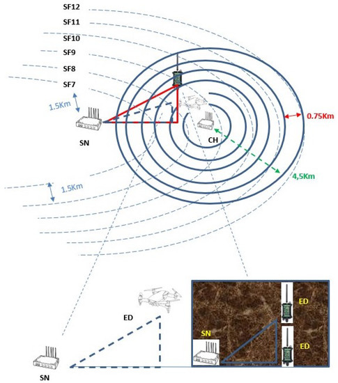
Figure 1.
Network architecture.
The system architecture is primarily based on the maximum transmission distance of the latest WuR technology as we consider that the maximum diameter of the external cycle is 9 km [21] and it can be utilized with ease in outdoor environment as opposed from existing works that have an additional circuitry like Bluetooth [22]. Keeping this in mind, it can be easily perceived that the moving EDs (either terrestrial or aerial and no matter where they are located) and the CH are always reachable with each other for WuB message exchange.
3.2. Operation of the Proposed Algorithm
The proposed algorithm was designed having in mind the mobility of the end nodes and their direct consequences in the operation of the network. As each ED has a generic moving pattern, controlled from specific parameters as shown in Table 1 and Table 2, it does not remain within the boundaries of a single SF. Due to their mobility, nodes may not be able to retain the same SF parameter during their operation as their distance from the SN may vary. Therefore, EDs should amend their transmission parameters in order to ensure the successful reception of their message. The proposed approach MOTILO (moving-based time-division multiple access for LORa) is described concisely below, while the corresponding pseudocode is depicted in Algorithm 1.
| Algorithm 1 MOTILO Algorithm |
| Input: N, , , , p, and
|

Table 1.
Notation.
Table 2.
LoRa radio settings.
MOTILO is mainly an enhanced migration of the system model of [6] for a protocol with moving nodes, tested also under dense node formations. Having said that, and similar to the model of [6], SN initiates the communication procedure by requesting the data from the nodes through the CH. Thus, SN sends a LoRa message to the CH and the latter broadcasts a WuR message to the EDs in order to acquire their intention of transmission, in other words, to probe if they have data to send. While in [6] the WuR is used as a trigger to start the transmission of the EDs’ data, in MOTILO the WuR is used to construct the transmission map by broadcasting the EDs’ position translated to the initial SF zone. Upon reception of this broadcast message, every ED initiates a GPS measurement and responds with a WuR broadcast message, announcing the calculated SF according to its position (lines 2–11 in Algorithm 1), in case it has data to transmit, under a simple transmission policy: according to its node ID inside the cluster, every nodes calculates its transmission slot (TS) by multiplying its ID with the WuR signal duration:
As a consequence, every ED has to wait for its transmission slot even if the previous nodes do not have data to transmit as there is no other way to be informed about other nodes’ intentions.
This is the first phase of the proposed communication protocol. In this phase, we are informed about the transmission intentions of every node, and is critical in order to schedule all the transmissions. Adding this latency, which is not present in the work of Piyare [6], MOTILO is able to eliminate empty slots. Therefore, phase one is in other words an empty-slot sieve. Subsequently, at the end of the previous protocol phase (phase one), all nodes are aware of others transmission schedule and each node is able to construct the global transmission slot schedule (variable in line 16 of Algorithm 1) in what is called phase two (lines 14–26 in Algorithm 1). Opposed to the base work of [6], as the nodes in our communication system are moving, MOTILO, acting as a forecast system, reserves an additional slot () in a higher SF zone () from the one reported from every node in phase one. This is performed in order to minimize the consequences of nodes that will change their position and the initially reported SF will be out of range, resulting in a lost packet or even two lost packets as their transmission may interfere with the transmission of another node. To do so, for every occupied transmission slot, one additional is reserved beforehand in the higher SF schedule. The logic behind this principle is to mitigate the possibility of a lost packet as mentioned above. Same as previously mentioned, phase two acts as a time scheduler with insurance being able to schedule all transmissions and in advance to reserve slots for all the nodes that would have change their position to a higher SF zone until the time of the actual transmission. The sequence diagram of Figure 2 represents in detail the operation of the MOTILO algorithm.
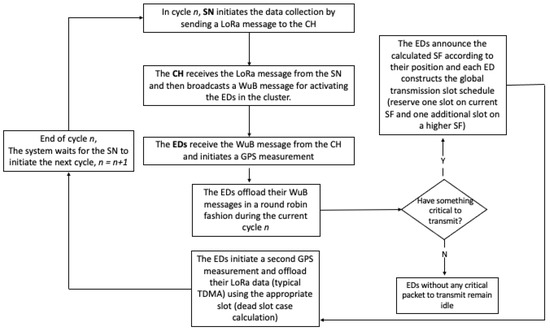
Figure 2.
Sequence diagram of the proposed MOTILO approach.
Latency-prone though it may seem, the proposed algorithm manages to overcome the latencies that may arise from the slot reservation, as from phase one it eliminates the empty slots and this counteracts for the additional reserved slots in phase two. Being also a point of segregation from the modified version of [6], MOTILO eliminates the collisions and for the majority of the moving patterns based on life-like scenarios, it can keep the lost packets in minimum levels. Taking into consideration the range of a LoRa transmission of a given SF, being roughly 2 km, it is not prohibited to transmit with a higher SF for shorter than its maximum theoretical range distances. On the other hand, transmissions with lower SF are not recommended for higher distances due to free space/structural attenuation.
Taking all the above into consideration, each ED builds the global transmission schedule and for every reserved slot from the first phase, it reserves another one for every node, in the SF + 1 schedule (line 15). That way, in case a node has sent its schedule for a specific SF and before the scheduled transmission time it has migrated to a higher SF zone, it can still utilize the higher SF with minimum possibility of a packet loss. If the node migrates to a lower SF zone, it can still utilize the higher SF as the lower SF time slot generally will not be available due to its shorter duration. We opted for this option in order to eliminate complicated queue mechanisms, being a protocol for IoT applications with mobile nodes without any exceptions due to energy or processing power limitations. Yet, additional round-trip latency may occur in the system when some of the pre-reserved time slots in higher SF zones are left unused in cases where some EDs have moved to lower SF zones (closer to the sink) or remained at the same position, and as a consequence they have to transmit their data using their lower SF’s time slot assignment. Phase two is the actual transmission of the packets from every node. Utilizing the GPS module, MOTILO does not rely on predefined ED positions as in [6]. Instead, it initializes one GPS measurement upon the reception of the WuR message and builds the transmission map. We referred to the map as the GPS measurement practically places every node inside the system’s topology. With this measurement, at the end of the phase one, every node is aware of its transmission slot. The second GPS measurement is fired just before the aforementioned slot. Therefore, if the ED has not changed SF zone, it will use the initial SF as reported. Otherwise, if the ED has migrated to a lower SF zone and the time of the initial SF slot has passed, the ED can utilize the higher SF that has been reserved by the algorithm. In case of a higher SF zone migration, the ED will make use of the reserved SF.
Given the fact that the MOTILO is based on the work of [6], we should recall the main differences between these two protocols. Primarily, Piyare’s work considers stationary nodes while MOTILO is based on moving nodes either aerial or terrestrial. Secondly, MOTILO utilizes a LoRa based GPS device in addition to the WuR transceiver that it has been used in [6]. Apart from the previous systemic differences, MOTILO eliminates empty transmission slots that are present in the basic work. In order to provide grounds for a proper validation and comparison of the proposed work, we opted to amend the work of [6] with the same rules as MOTILO and for an even equitable comparison we end up with a second version of the [6] offering the second GPS measurement that MOTILO uses. As analyzed below, the amended versions of [6] have different operational characteristics in order to provide a wider enveloping for the performance comparisons with MOTILO.
There are two significant observations from the above algorithm. Firstly, due to the relation between speed of motion, the transmission range and the number of nodes for each system, we do not consider the cases that a node will move so fast to cover more than the range of a single SF zone between phase one and phase two of the proposed algorithm. The second observation is related to a possible “dead slot” situation (lines 26–27): as every node waits for its turn based on its ID, whenever the time of the first assigned slot (the one to the lower SF) has already elapsed due to the priority of the previous nodes and the node has migrated to the higher SF zone, the node will not be able to transmit without collision. For that reason, in case of a dead slot, every node amends on the fly its schedule and transfers its time slot to the end of the schedule for its higher SF option (variable in line 27). Therefore, whenever a node faces a dead slot situation, postpones its transmission until all the other nodes, which are scheduled to transit to the higher SF, end their second phase. Afterwards, the node starts its transmission at the first available time slot and the same applies also for all other nodes that have faced a dead slot case (Figure 3). Due to the fact that all the nodes are aware of the program and the possible collisions of each node, they are able to calculate all the dead slots and react accordingly. This is performed via a single preamble overhear. As the possible dead slot distribution is known beforehand, every node overhears the preamble of the previous node id that faces a possible dead slot. The interested node opens its circuitry at the scheduled slot for the previous node id that will face a possible dead slot. Whenever the previous node transmits a message, the next node will be aware of this information from the preamble. If the latter node does not receive the appropriate preamble, it will automatically schedule its lost transmission knowing that the previous node will utilize a slot at the end of the higher SF. This process has to be carried out for all the interested nodes and the higher the ID of the node, the higher the number that may open their circuitry as they have to be aware of all the previous used/unused slots.While the probability of a dead slot situation is increased for higher ED IDs, the operation of the MOTILO ensures that all the nodes will transmit their data without any lost transmission. As mentioned above, when utilizing the preamble overhearing mechanism, all the involved nodes schedule their transmission. As a consequence, some nodes may face increased latency as they will have to postpone their transmission for the free slots at the end of the MOTILO scheduling. For these nodes, there is no metric about their increased latency but the same applies for all the nodes that have a high ID, as most of the algorithms base their node prioritization on their node ID. In other words, nodes with higher IDs will be ranked at the end of any list that has to sort them without any other characteristic. With the same rationale, some nodes will face increased latency based on the dead slot situation of the MOTILO, but this is similar to having an initially increased ID.
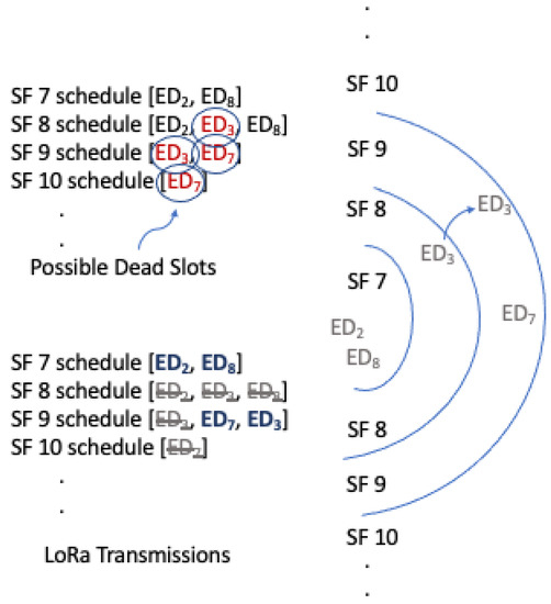
Figure 3.
Possible dead slots.
4. Simulation Results
In this section, the performance of the proposed protocol is evaluated for different simulation scenarios. In that context, a LoRa network simulator has been implemented using Python 3.7 on Spyder running macOS 12.1 Monteray with 2.2-GHz Intel Core i7 Processor. The simulator models the MAC operation of the proposed protocol in detail, while using only the absolutely necessary elements to represent the physical layer. Feeding the model with the values from Table 1, Table 2 and Table 3, and setting the number of simulation iterations to , we analyze the mean data latency in these life-like scenarios as the primary metric for the network performance. This metric measures the time that elapses from the initial LoRa message of the sink to the CH until the last node transmits its data. More specifically, the mean data latency (MDL) is calculated over all the numbers of simulation runs. For every case, we set the load and we store for every run the data latency. As the data latency is related to the ID of the last node that has data to transmit, we opted to run every case for runs in order to smooth out any discrepancies.
Table 3.
Variables and parameters.
Before we delve into the results and in order to enhance the readership of this work, we analyze the parameters used in the simulation testbed. The moving speed value was set to 25 m/s to cover the higher segment of mobile devices from automobiles to drones. Under the same rationale, the frequency of direction changes was also selective to be indicative for the number of times per second the processing unit of the object may end up changing the direction.
While the most recent WuR transmitters have data rates well beyond 1 kb/s, we opted for this value so as to be consistent with the values from the work that we compare to the proposed protocol. All the sizes of the WuR messages are the minimum in order to transfer the required information of the protocol to the nodes. Finally, as stated above, the maximum range of the WuR was set to 9 km and for that reason every SF ring zone has a width of 1.5 km. In the following scenarios we compare the suggested algorithm with a direct transfer of the work in [6], amended appropriately to encompass moving nodes (TDMA-PL). In detail, the sink initiates the data transmission and requests data from the EDs by sending a LoRa message to the CH. The latter notifies the EDs with a WuB message for the scheduling of LoRa messages (TDMA). Using GPS, each ED calculates its position and sends LoRa messages back to the sink using the time slot corresponding to its id and the SF according to its calculated geographic position (e.g., ED with ID = 5 and SF 7 sends its LoRa packet in ToA(7) × 5 ms). In case the ED has changed its position to a higher S, then it faces a packet loss. Moving one step forward, we test our protocol with another variation of the work in [6] that executes a second GPS measurement as our algorithm does. This diminishes the possibility of a lost packet. The results of this aforementioned protocol are denoted as TDMA-2M. If the second GPS measurement is outside the initial SF ring and migrated to a higher SF, then the ED does not initiate the transmission as it would result in lost packet. Nevertheless, under TDMA-2M implementation the node is able to send its packet by reserving the appropriate time slot according to its id using the higher SF as determined from the second GPS measurement.
In order to have an estimation about the mean data latency, we consider the following terms:
- N corresponds to the number of EDs considered in each network scenario.
- L corresponds to network load and varies from 10% to 100%. For example, a value of load at 50% indicates that for this cycle, half of the nodes will have data to transmit and a 100% loads means that in this cycle all the EDs will request a slot for transmission.
- (average time on air) stands for the average time (in ms) that takes for all the signals before the receiver receives them. This is a statistical factor extrapolated from the averaging between the 6 different ToA derived from the 6 SFs.
- (Average LoRa message) is the time needed (in ms) for all the nodes to transmit their messages averaged by the load. This factor refers to the average time needed by the EDs to complete a simulation cycle and is directly related to the load and the number of EDS along with the average ToA.
In case of a stationary system, the average delay would be calculated from the following relation as there are 4 basic components: (a) the LoRa message from SN to the CH, (b) the WuR message from CH to the EDs, (c) the broadcast messages from the EDs to inform about their data availability, and finally (d) the actual LoRa message from the EDs to the SN:
For moving nodes, the term aToA (average Time on Air) changes as the EDs move inside the simulation area and change the SF based on the time it has elapsed from the first phase of the algorithm. While this is a continuous-time random walk and may require the probability functions for the number of jumps and the position, the averaging rationale simplifies the following formulation. We consider that for the total time of running m EDs will change SF zone, which is directly based on the total number of EDs. A system with a small number of EDs means that there will not be enough time for the EDs to move and change SF zone. On the other hand, a system with a higher number of EDs means that numerous nodes will have ample time to move and change their SF zone as they will have to wait for a larger number of EDs to complete their transmission prior to their own time slot. Without the accuracy of the aforementioned stochastic processes, as the process is random, from the m nodes that will have changed their SF, (m is a small percentage of all the nodes that will have changed their SF at the end of the simulation) half of them will have moved to a higher SF and the others to the lower SF. Those who will change their SF zone to a higher one will increase the aToA by that percentage while the others will keep their initial SF. As a result, the relation (3) will read:
The term is obtained using the Equation (5), while the terms , , … and corresponds to the number of nodes that have moved from one SF (SF) to a higher one (SF + 1) (i.e., refers to all the nodes that have moved from SF7 to SF8). We should note here that term does not take part in the calculations as all the nodes that are inside the SF12 zone at phase one do not have the option to migrate to a higher SF zone but they are calculated in the mean value .
Taking into consideration all the above, we expect a higher mean data latency, related to the stationery case, by the factor [SF] which stands for a mean value for all the nodes that will get a higher SF. This factor is not the same as the aToA as contains the nodes that have migrated to a higher SF except those that were already at the SF 12 (we assume that they will not leave the simulation area). Contradictory though it may be, MOTILO manages to mitigate this increment by adding phase one of the protocol. Utilizing the knowledge of intentions for transmitting from phase one, nodes are able to schedule their transmission program eliminating empty time slots, resulting in lower values of mean data latency. Future work will investigate the analytic form of the [SF].
For a network with 9 nodes (Figure 4a) starting from random positions inside the testbed area, the mean data latency is shown in Figure 5a. The nodes move in an endless random pattern subjected to the parameters of Table 2. While the performance of the two TDMA protocols are almost identical (the second GPS measurement for the TDMA-2M as mentioned above helps to avoid lost packets) and at the levels of 1.6 s, the proposed protocol delivers a latency improvement starting from 31% and reaching 62% in case of a single node for transmission. The main advantage of the algorithm is that it spends time listening to the intentions of the nodes and then assigns slots only to the nodes that have data to transmit.
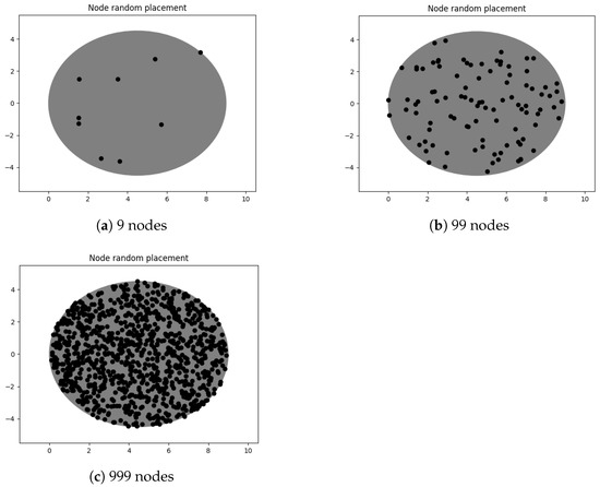
Figure 4.
Random placing of (a) 9, (b) 99 and (c) 999 EDs.
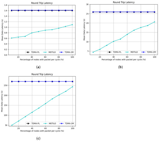
Figure 5.
Mean data latency (s) under variable traffic load for LoRa networks with (a) 9, (b) 99 and (c) 999 EDs.
As expected, when we add more nodes to the simulation (Figure 4b and Figure 5b), the performance gap is widening as the MOTILO algorithm is able to achieve up to almost 85% lower latency for the lighter loads, while when all the nodes have data to transmit the gap closes up to 21%. For the same reasons as stated above, both TDMA variations have the same latency but the TDMA-2M avoids lost packets.
Finally, in the last simulation we test MOTILO in highly dense network (Figure 4c) formations standing also as another point of segregation from existing protocols. As shown in Figure 5c, MOTILO retains the same performance characteristics versus the TMDA-based protocols. It is interesting though to point out that while in the previous two simulation scenarios the 2M protocol had a minuscule performance advantage versus the PL, in this scenario there is no visible difference between them. This is more probably due to the smaller covariance of the system due to the high enough number of nodes.
Moreover, it is meaningful to examine the average packet loss during the implementation of the presented algorithms (TDMA-PL, TDMA-2M and MOTILO). Similarly to the mean data latency average packet loss (APL) is calculated over all the runs in order to minimize any statistical errors. For every run, we calculate the packets that are not delivered due to node migration to higher SF Zones. The sum of all these packets is divided by the total number of runs for this metric. Again the
In detail, Figure 6 shows the average number of lost packets per TDMA cycle when the number of network nodes varies from 9 to 999 nodes. We opted for the case of 100% loads (as our worst case scenario) as in all other network load values our algorithm significantly outperforms the other two algorithms. It can clearly be seen that the TDMA-PL algorithm which constitutes a direct transfer of [6] presents a considerable rate of lost packets, with this number rising progressively as the number of EDs increases. This is explained by the fact that all EDs try to send their packets only to the initial time slot assigned to them, while suffering from a potential packet loss in case some of them have moved to a higher SF zone. On the contrary, pertaining to the TDMA-2M, the number of packet loss is reduced to zero for all the cases as the algorithm executes a final GPS measurement before the data transmission and amend its SF accordingly. The direct result of this process though is the increased data latency. MOTILO, on the other hand, achieves decreased data latency with minimum packet losses. proving the ability of the algorithm to adapt to the possible movements of the EDs in zones with a higher SF, since it was given the opportunity to use a time slot belonging to a higher SF. As seen from the Figure 6, for denser network formations, MOTILO faces some packet losses as the increased number of nodes results in longer moving periods and this means increased probability for a two or more SF leaps. However, the proposed protocol maintains the mean data latency significantly lower compared to the TDMA-2M algorithm, as verified by the line graphs presented and analyzed above (Figure 5a–c).
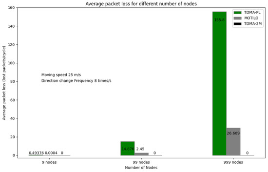
Figure 6.
Average packet loss under TDMA-PL, TDMA-2M and MOTILO algorithms.
From the above performance analysis, it is apparent that MOTILO, being an IoT-oriented LoRa protocol can be utilized to orchestrate moving nodes in wide area coverage applications. As such, forest fire detection applications that combine terrestrial and aerial surveillance means like autonomous robots and UAVs respectively, could be benefited from the low number of lost transmissions and the low mean data latency in order to provide near time information to the monitoring headquarters. Another field of possible use would be the vehicular ad hoc networks (VANET) as the speeds and the number of nodes are in accordance to the usable range of the WuR utilized in MOTILO. That way, LoRa transceivers could be used for mobile data offloading. In agriculture and farming, as mobile network coverage may be limited due to the special characteristics of remote farms, MOTILO could be used to track and synchronize self driving tractors and other farming machines. Additionally, MOTILO could be adopted in battlefield as a primary or backup communication system to integrate all military machinery such as tanks, helis, soldier units, moving artilleries, and military drones. The number of supported nodes and their actual velocities do not differ from the scenarios that were investigated in this work. Future protocol amendment would handle unlimited number of SF zone migrations, render the future version of MOTILO an ideal candidate for applications with zero-tolerance in lost packets and minimum latency.
Another interesting set of simulation scenarios is shown in Figure 7. In this figure, we test the link between the mean data latency and the speed of nodes and the number of direction changes of the moving pattern. As shown in this figure, there is a slight improvement with the increased speed. This is not a direct relation between the speed of the EDs and the operation of the MOTILO but more a result of the simulation testbed. Due to the operation of MOTILO, the nodes with the higher SFs affect the mostly the total mean data latency as the higher the number of them, the more the latency the system will face as the additional slots that will be reserved will be in the most time-demanding SF zones. For example, a node that is in the SF7 zone will insert a possible ToA(8) time-slot delay while a node in SF1 will insert a possible SF(12) time-slot delay. As the ToA(12) is almost 30 times higher than ToA(7) it become apparent that the EDs at the higher SF zones have a predominant effect to the total Mean data latency. Moreover, the aforementioned nodes as they are already at the boundaries of the simulation area, they only move to the inner sections of the testbed as time passes. Their final position is based on the random walk properties and as a result the most possible outcome is to be found in lower SF zone after the initialization of the simulation.
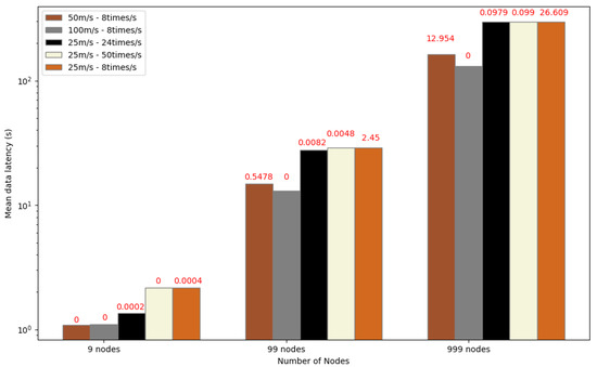
Figure 7.
Mean data latency under different simulation scenarios of MOTILO algorithm. Values illustrated with red color corresponds to the average packet loss.
Being a protocol for IoT applications with moving nodes and limited energy resources, in Figure 8 we calculate the expected lifetime of the network by comparing all the protocols presented in this work. MOTILO, due to the elimination of the empty slots in comparison to the other two approaches, manages to offer almost 3 times more days of operation until the energy exhaustion of the nodes. We calculated the mean energy consumption of the nodes and we projected the life time of them based on a 1200 mAh battery as shown in Table 3. This metric is based on a 10 s cycle for all the protocols and as expected, for lighter load conditions MOTILO outperforms the other solutions and keeps that advantage for loads up to 70%. After that load, nodes in MOTILO consume higher amounts of energy in comparison to the TDMA-PL, primarily due to the second GPS measurement along with the addition of phase one where all nodes need to open their circuitry in order to inform about their intention for transmission. For 100% load, MOTILO and TDMA-2M offer the same network lifetime, while the TDMA-PL offers almost 28% more. However, one should recall that TDMA-PL does not offer lost packet protection while the other two protocols offer increased protections against lost packets due to ED motion.
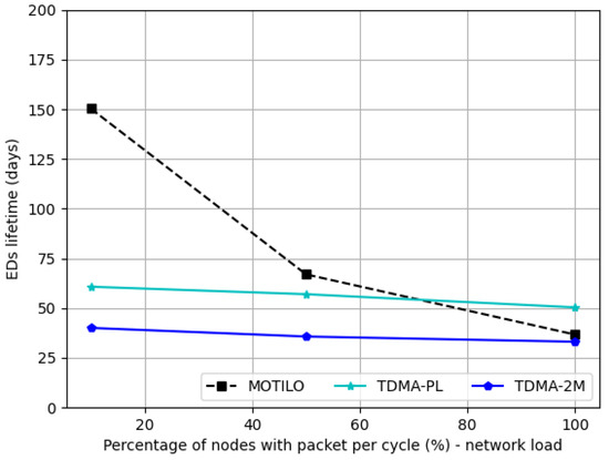
Figure 8.
Energy evaluation of TDMA-PL, TDMA-2M and MOTILO algorithms for 9 EDs.
5. Conclusions
With a focus on moving nodes within a LoRa network and with the assistance of a high range WuR transmitter, this article proposed an access protocol to minimize data latency and the possibility of packet loss. Our study unveiled that the proposed communication scheme outperforms existing solutions from the literature in data latency. Such deductions instate the use of MOTILO as a sturdy solution for mobile IoT networks. A future version of the algorithm will handle the migration of a node for more than one SF zone in order to eliminate any packet loss and will be capable of even ultra high-speed nodes. As a future work, we intend to evaluate the performance of the proposed protocol in scenarios that will model in detail the fading and propagation fluctuation phenomena in the wireless medium, so that the algorithm can more accurately adjust the duration of the reserved time slot based on more realistic network conditions. Moreover, the future version of MOTILO will be amended accordingly so as to cope with unlimited SF zone migrations while offering zero lost transmissions without sacrificing mean data latency. Figure 7 depicts this result, as the system with the higher velocity nodes seems to have zero lost packets in addition to the slightly better mean data latency. Under the same rationale, nodes with the same speed but more change directions result in the same mean data latency but their packet loss is not the same’ as for the case with less direction changes, their movement pattern creates less dense formations while more directions changes result in denser formations and by this way the nodes have more time to return to their initial position.Less direction changes mean that their movement pattern will have many indentations while higher number of direction changes result in more flattened moving patterns resulting in less SF migrations.
Author Contributions
Conceptualization, K.F.K. and G.A.B.; methodology, K.F.K., G.A.B. and A.V.; software, K.F.K. and G.A.B.; validation, K.F.K., G.A.B., A.V., P.N. and G.I.P.; investigation, K.F.K., G.A.B. and A.V.; writing—original draft preparation, K.F.K. and G.A.B.; writing—review and editing, K.F.K., G.B, A.V., P.N. and G.I.P.; supervision, P.N. and G.I.P. All authors have read and agreed to the published version of the manuscript.
Funding
This research has been co financed by the European Union and Greek national funds through the Operational Program Competitiveness, Entrepreneurship and Innovation, under the call RESEARCH-CREATE-INNOVATE 2 (project code: T2EDK-02617).
Informed Consent Statement
Not applicable.
Data Availability Statement
Not applicable.
Conflicts of Interest
The authors declare no conflict of interest.
References
- Zourm, A.; Hing, A.L.K.; Hung, C.W.; AbdulRehman, M. Internet of things (IoT) using LoRa technology. In Proceedings of the 2019 IEEE International Conference on Automatic Control and Intelligent Systems (I2CACIS), Selangor, Malaysia, 29 June 2019; pp. 324–330. [Google Scholar]
- Polonelli, T.; Brunelli, D.; Marzocchi, A.; Benini, L. Slotted ALOHA on LoRaWAN-design, analysis, and deployment. Sensors 2019, 19, 838. [Google Scholar] [CrossRef] [PubMed]
- Beltramelli, L.; Mahmood, A.; Österberg, P.; Gidlund, M. LoRa beyond ALOHA: An investigation of alternative random access protocols. IEEE Trans. Ind. Inform. 2021, 17, 3544–3554. [Google Scholar] [CrossRef]
- Georgiou, O.; Raza, U. Low power wide area network analysis: Can LoRa scale? IEEE Wirel. Commun. Lett. 2017, 6, 162–165. [Google Scholar] [CrossRef]
- Laya, A.; Kalalas, C.; Vazquez-Gallego, F.; Alonso, L.; Alonso-Zarate, J. Goodbye, ALOHA! IEEE Access 2016, 4, 2029–2044. [Google Scholar] [CrossRef]
- Piyare, R.; Murphy, A.L.; Magno, M.; Benini, L. On-demand LoRa: Asynchronous TDMA for energy efficient and low latency communication in IoT. Sensors 2018, 18, 3718. [Google Scholar] [CrossRef] [PubMed]
- Piyare, R.; Murphy, A.L.; Magno, M.; Benini, L. On-demand TDMA for energy efficient data collection with LoRa and wake-up receiver. In Proceedings of the 2018 14th International Conference on Wireless and Mobile Computing, Networking and Communications (WiMob), Limassol, Cyprus, 15–17 October 2018; pp. 1–4. [Google Scholar]
- Beletsioti, G.A.; Kantelis, K.F.; Valkanis, A.; Nicopolitidis, P.; Papadimitriou, G.I. A Multilevel TDMA approach for IoT applications with WuR support. IEEE Internet Things J. 2022, 9, 22785–22795. [Google Scholar] [CrossRef]
- Spathi, K.; Valkanis, A.; Beletsioti, G.; Kantelis, K.; Nicopolitidis, P.; Papadimitriou, G. Learning-Automata-Based Energy Efficient Model for Device Lifetime Enhancement in LoRaWAN Networks. In Proceedings of the 2022 International Conference on Computer, Information and Telecommunication Systems (CITS), Piraeus, Greece, 13–15 July 2022; pp. 1–6. [Google Scholar] [CrossRef]
- Gupta, A.; Fujinami, M. Battery optimal configuration of transmission settings in LoRa moving nodes. In Proceedings of the 2019 16th IEEE Annual Consumer Communications & Networking Conference (CCNC), Las Vegas, NV, USA, 11–14 January 2019; pp. 1–6. [Google Scholar]
- Bouras, C.; Gkamas, A.; Salgado, S.A.K. Energy efficient mechanism for LoRa networks. Internet Things 2021, 13, 100360. [Google Scholar] [CrossRef]
- Saraereh, O.A.; Alsaraira, A.; Khan, I.; Uthansakul, P. Performance evaluation of UAV-enabled LoRa networks for disaster management applications. Sensors 2020, 20, 2396. [Google Scholar] [CrossRef] [PubMed]
- Pan, M.; Chen, C.; Yin, X.; Huang, Z. UAV-aided emergency environmental monitoring in infrastructure-less areas: LoRa mesh networking approach. IEEE Internet Things J. 2021, 9, 2918–2932. [Google Scholar] [CrossRef]
- Kim, D.H.; Park, J.B.; Shin, J.H.; Kim, J.D. Design and implementation of object tracking system based on LoRa. In Proceedings of the 2017 International Conference on Information Networking (ICOIN), Da Nang, Vietnam, 11–13 January 2017; pp. 463–467. [Google Scholar]
- Andrei, M.L.; Rădoi, L.A.; Tudose, D.Ş. Measurement of node mobility for the LoRa protocol. In Proceedings of the 2017 16th RoEduNet Conference: Networking in Education and Research (RoEduNet), Targu-Mures, Romania, 21–23 September 2017; pp. 1–6. [Google Scholar]
- Fernandez, A.A.; Rakhmatsyah, A.; Wardana, A.A. Monitoring Floating Solar Tracker based on Axis Coordinates using LoRa Network. Int. J. Renew. Energy Dev. 2020, 9, 141–149. [Google Scholar] [CrossRef]
- Sciullo, L.; Trotta, A.; Di Felice, M. Design and performance evaluation of a LoRa-based mobile emergency management system (LOCATE). Ad Hoc Netw. 2020, 96, 101993. [Google Scholar] [CrossRef]
- Fern, O.N.; Loke, S.W.; Avazpour, I.; Chen, F.F.; Abkenar, A.B.; Ibrahim, A. Opportunistic fog for IoT: Challenges and opportunities. IEEE Internet Things J. 2019, 6, 8897–8910. [Google Scholar]
- Kyung, Y. Performance Analysis of Task Offloading with Opportunistic Fog Nodes. IEEE Access 2022, 10, 4506–4512. [Google Scholar] [CrossRef]
- Lohachab, A.; Jangra, A. Opportunistic internet of things (IoT): Demystifying the effective possibilities of opportunisitc networks towards IoT. In Proceedings of the 2019 6th International Conference on Signal Processing and Integrated Networks (SPIN), Noida, India, 7–8 March 2019; pp. 1100–1105. [Google Scholar]
- Frøytlog, A.; Haglund, M.A.; Cenkeramaddi, L.R.; Jordbru, T.; Kjellby, R.A.; Beferull-Lozano, B. Design and implementation of a long-range low-power wake-up radio for IoT devices. In Proceedings of the 2019 IEEE 5th World Forum on Internet of Things (WF-IoT), Limerick, Ireland, 15–18 April 2019; pp. 247–250. [Google Scholar]
- Wang, W.; Zang, C.; Chen, Z.; Liu, S. Mobile Node Design of Indoor Positioning System Based on Bluetooth and LoRa Network. J. Phys. Conf. Ser. 2021, 1738, 12092. [Google Scholar] [CrossRef]


Disclaimer/Publisher’s Note: The statements, opinions and data contained in all publications are solely those of the individual author(s) and contributor(s) and not of MDPI and/or the editor(s). MDPI and/or the editor(s) disclaim responsibility for any injury to people or property resulting from any ideas, methods, instructions or products referred to in the content. |
© 2023 by the authors. Licensee MDPI, Basel, Switzerland. This article is an open access article distributed under the terms and conditions of the Creative Commons Attribution (CC BY) license (https://creativecommons.org/licenses/by/4.0/).