Article

The Prescribed-Time Sliding Mode Control for Underactuated Bridge Crane

School of Electrical and Control Engineering, Shaanxi University of Science and Technology, Xi’an 710021, China
*
Author to whom correspondence should be addressed.
Electronics 2024, 13(1), 219; https://doi.org/10.3390/electronics13010219
Submission received: 10 December 2023 / Revised: 25 December 2023 / Accepted: 29 December 2023 / Published: 3 January 2024
(This article belongs to the Special Issue High Performance Control and Industrial Applications)

Abstract

:
In this article, a prescribed-time sliding mode controller is proposed for the design of the positioning and anti-swing time of the underactuated bridge crane under different initial conditions. Compared with the existing crane positioning and anti-swing controller, the controller can directly specify the positioning and anti-swing time of the bridge crane system through the controller parameters. Firstly, in order to solve the underdrive problem of the bridge crane system, the crane system model is transformed by constructing composite variables; secondly, a new prescribed-time convergence rate and a new prescribed-time sliding mode surface are designed to ensure that the state of the bridge crane system can converge within the prescribed time; finally, the Lyapunov stability analysis and simulation results show that the designed controller can enable the crane to position and anti-swing within the prescribed time.

1. Introduction

As a large cargo-handling tool, the bridge crane is widely used in the steelmaking process for its strong load capacity and flexible operation. However, the inherent structural characteristics of the crane will cause the ladle to swing during the transfer process, which will reduce the transfer efficiency and accuracy, and there are certain safety hazards. For the steel water transfer process, the design of the crane’s positioning and anti-swing time is critical: too short a time for the crane to transfer the steel water will lead to a large load swing angle of the crane system, which will easily cause the ladle to crash into the surrounding equipment and cause safety accidents; too large a time for the crane to transfer the steel water will lead to a large temperature drop in the steel water and cause a waste of resources. Therefore, setting the time for trolley positioning and load demobilization in a bridge crane system directly through controller parameters represents a challenging and valuable research problem.
The problem of positioning and swing elimination in bridge crane systems has been extensively researched. This research encompasses open-loop control methods such as input shaping [1] and trajectory planning [2,3], as well as closed-loop control methods, like PID control [4,5], backstepping control [6,7], fuzzy control [8], and sliding mode control [9,10,11,12]. The core idea of input shaping and trajectory planning is to design the acceleration of the trolley, so as to reduce the swing of the load as much as possible during the movement of the trolley. However, the open-loop control has the problem of poor robustness, and it is difficult to eliminate the swing angle of the load in case of external disturbances, such as wind, so many scholars combined with the closed-loop control methods and further researched the problem of positioning and swing elimination of a bridge crane system. Since the sliding mode control has a strong anti-interference ability, it has been applied to the positioning and swing elimination problem by many scholars. To address the underactuated problem inherent in bridge crane systems, Wang, T.L. [13] transformed the bridge crane model and proposed a sliding mode positioning and anti-swing controller based on feedforward control. Chen, Q.R. [14] decoupled the bridge crane system model and proposed a sliding mode controller that operates without needing load parameter information. Nguyen, L. [15] divided the bridge crane system into a position subsystem and a swing angle subsystem. Sliding mode surfaces for each subsystem were designed separately. Moreover, the sliding mode surfaces of both the position and swing angle subsystems were integrated to form a comprehensive sliding mode surface. A hierarchical sliding mode controller was designed to achieve trolley positioning and eliminate load swing. Wang T.L. [16] designed a sliding mode controller without a convergence phase for the secondary pendulum characteristics exhibited by a bridge crane during large load handling. Yang, W.L. [17] combined hierarchical sliding mode control and terminal sliding mode control to design a hierarchical global terminal sliding mode controller, and the simulation results showed that the load swing angle of the bridge crane system would converge asymptotically. All of the aforementioned control methods enable the bridge crane system to position and anti-sway. However, to enhance the efficiency of the bridge crane, the load transfer time may require an upper-bound constraint, which may not be satisfied by the controller designed above. To address the issue of not having an upper bound on the positioning and anti-swing time of the bridge crane, the controller design combined with finite time stability can solve this problem. For this reason, combined with finite-time stability theory, Xin, W. [18] proposed a novel sliding mode controller combined with adaptive control to address the challenge of tracking a bridge crane in the presence of unknown cable length and load mass. The designed controller ensures that the crane achieves trolley positioning in finite time, but the swing angle of the load asymptotically converges. Nguyen V.T. [19] linearized the bridge crane system, established a fuzzy model for the bridge crane, and combined finite time stability to propose a fuzzy sliding mode controller. Gu, X.T. [20] considered the effects of external disturbances during the operation of a bridge crane, designed a disturbance observer for estimating the disturbance in a finite time, and combined it with a sliding mode control for controller design. Wu, X.Q. [21] transformed the original dynamics model of the crane system and subsequently proposed a finite time controller. This designed controller can estimate disturbances in finite time and ensure that the bridge crane system state converges within a finite time. In references [22,23], Zhang, M.H. designed a terminal sliding mode controller based on the finite time stability theory, which ensures that the load can be carried to the target position within a finite time. The aforementioned method ensures that the bridge crane can achieve positioning and anti-swing in a limited time, but the aforementioned method suffers from the problem that the load-handling time is affected by the initial conditions of the system, and the researcher is unable to set the time of load handling in advance under different conditions. Further, Wu, X.F. [24] converted the crane system model into a high-order system and combined the fixed-time stability theory and backstepping control to design a fixed-time positioning and anti-swing controller, which ensured that the crane carried the loads for a fixed period of time that was not related to the system’s initial state. However, because the positioning and anti-swing time are determined by complex functional relationships between multiple controller parameters, this leads to difficulties in the design of crane positioning and anti-swing time, which limits its application in practice.
Prescribed-time stabilization is a special type of finite-time control that ensures that the convergence time of the system can be preset directly by the controller parameters, which is unrelated to system’s initial state. It has been effectively applied in the control problems of fully driven systems, for example, chaotic system synchronization [25], multi-intelligent body system consistency [26,27,28,29], vehicle control [30,31], and robotic arm [32]. Good control results have been achieved. Since there are more state quantities than drive quantities in underactuated systems, it is not guaranteed that each state quantity converges in the prescribed time, so it is difficult to combine the prescribed-time stability theory with underactuated systems, and there are no prescribed-time stability-related studies reported for underactuated systems.
The contributions made in this article are as follows:
(1)
The two-dimensional bridge crane model was transformed into a chain system by linearizing the crane model and constructing auxiliary variables, simplifying the design difficulty of the underactuated bridge crane system’s prescribed-time positioning and anti-swing controller.
(2)
A new type of prescribed-time convergence rate was proposed herein. At the same time, the continuous prescribed-time convergence rate eliminates the chattering problem inherent in the switching term of the sliding mode control.
(3)
A new type of prescribed-time sliding surface has been proposed to ensure that the position of the trolley and the pendulum angle of the load converge to the desired position on the sliding surface within the prescribed time.

2. Problem Description

The two-dimensional bridge crane model is depicted in Figure 1. Due to the system having fewer inputs compared to the number of system states, the bridge crane system represents a typical underactuated system.
Based on the Lagrangian dynamics equation, the two-dimensional overhead crane model is established as follows [15]:
M + m x ¨ + m l θ ¨ cos θ m l θ ˙ 2 sin θ = F ,
m l 2 θ ¨ + m l x ¨ cos θ + m g l sin θ = 0 ,
The parameters in bridge crane Models (1) and (2) are specified as illustrated in Table 1.
The control objective of a two-dimensional bridge crane system is to transport a load to a target location within a specified time while eliminating load swing and minimizing the load swing angle during transportation. These objectives can be articulated as follows:
lim t T ( x , θ ) ( x d , 0 ) ,
In Equation (3), x d represents the position at which the trolley is expected to arrive.
As shown in Figure 1, the load swing angle can only be controlled indirectly through the trolley position, so the time to eliminate the load swing is challenging to design. To achieve precise trolley positioning and eliminate load sway within a prescribed time, addressing the underactuated nature of the bridge crane system model is crucial. This paper addresses this by transforming its dynamic model into an all-drive crane system model through linearization and the construction of auxiliary variables. Secondly, according to the converted all-drive crane system model combined with the prescribed-time stability theory, the positioning and anti-swing time are introduced into the controller parameters so that the bridge crane system’s positioning and anti-swing time can be directly preset by the controller parameters. It is designed so that the trolley can be positioned within the prescribed time while eliminating the swing of the load. Finally, the bridge crane system’s positioning and anti-swing time are demonstrated using the Lyapunov stability principle and simulation experiments. Moreover, to verify that the designed controller can achieve the desired goal, three sets of different simulation experiment conditions are designed while keeping the controller parameters unchanged. Figure 2 presents the research approach of this article.

3. Bridge Crane Model

In the preceding section, it was pointed out that it is difficult to design the positioning and anti-swing time for bridge crane systems due to their underactuated characteristics. Therefore, this section converts the system model into a chained-form system by linearizing the crane model and constructing auxiliary variables, which solves the crane system underdrive issue and simplifies the design difficulty of the prescribed-time positioning and anti-swing controller.
Rewriting Equation (2) in the following form, we obtain:
x ¨ = g tan θ l θ ¨ cos θ ,
By replacing Equation (4) into Equation (1), we can conclude:
θ ¨ = M + m g sin θ + m l θ ˙ 2 sin θ cos θ + F cos θ M l + m l sin 2 θ ,
Therefore, further equivalencing the 2D bridge crane model results in the following form:
x ¨ = g tan θ l θ ¨ cos θ θ ¨ = M + m g sin θ + m l θ ˙ 2 sin θ cos θ + F cos θ M l + m l sin 2 θ ,
The angle of swing is desired to be as small as possible when the crane is in operation, so the following assumptions are made: cos θ = 1 ,   sin θ = θ , θ ˙ 2 = 0 , θ 2 = 0 [33] to linearize the two-dimensional bridge crane Model (6). Meanwhile, the state quantity will be defined as x 1 , x 2 , x 3 , x 4 = x , x ˙ , θ , θ ˙ , the system input as u = F , and the linearized model is shown below.
x ˙ 1 = x 2 x ˙ 2 = g x 3 l x ˙ 4 x ˙ 3 = x 4 x ˙ 4 = ( M + m ) g M l x 3 1 M l u ,
To simplify the design challenge of a prescribed-time controller and ensure that the bridge crane system achieves both trolley positioning and load anti-swing, it is essential to eliminate the x ˙ 4 in the right equation of Model (7) and, therefore, define the following auxiliary variable.
ζ 1 = x 1 + f ( x 3 ) ,
The first- and second-order derivatives of the auxiliary variable (8) are as follows.
ζ ˙ 1 = x 2 + f ( x 3 ) x 3 x 4 ,
ζ ¨ 1 = x ˙ 2 + 2 f ( x 3 ) x 3 2 x 4 2 + f ( x 3 ) x 3 x ˙ 4 ,
To eliminate x ˙ 4 in Equation (10) and combine Model (7) with Equation (10), it is necessary to construct the following equation to hold:
f ( x 3 ) x 3 x ˙ 4 l x ˙ 4 = 0 ,
Thus, we can obtain the following:
f ( x 3 ) = l x 3 ,
Therefore, the following state variables are defined.
ζ 1 = x 1 + l x 3 ζ 2 = x 2 + l x 4 ζ 3 = g x 3 ζ 4 = g x 4 ,
Further, Model (7) is transformed in the following form.
ζ ˙ 1 = ζ 2 ζ ˙ 2 = ζ 3 ζ ˙ 3 = ζ 4 ζ ˙ 4 = ( M + m ) g M l ζ 3 + g M l u ,
The transformation of Model (7) into Model (14) is achieved by constructing auxiliary variables while transforming control Objective (3) into lim t T ζ 1 , ζ 2 , ζ 3 , ζ 4 x d , 0 , 0 , 0 . Therefore, in the subsequent study, we will focus on Model (14) and proceed with the design of a prescribed-time positioning and swing damping controller.

4. Controller Design

In the present section, the sliding mode controller was designed, which can preset the bridge crane positioning and swing elimination time directly through the controller parameters. The design of the sliding mode controller is divided into two stages: firstly, it is necessary to design the sliding mode surface that can preset the convergence time through the controller; secondly, it is vital to design a new convergence rate that can preset the arrival time through the controller. Only when the above two requirements are satisfied can the bridge crane be realized to locate and eliminate the swing within a prescribed time, while the time for locating and eliminating the swing is directly set by the controller. The controller design is performed in combination with the fully actuated model (14).
For System (14), when the system state ζ 1 converges to the desired position x d within the prescribed time, the system states ζ 2 , ζ 3 , and ζ 4 also converge to zero. This implies that the bridge crane system achieves the control objectives within the prescribed time. As a result, the system state error is defined as follows.
e = ζ 1 x d ,
To ensure that the system error converges to zero within a prescribed time after reaching the sliding surface, it is necessary to ensure that the sliding surface itself converges within the prescribed time. By combining the prescribed-time stability theory, a novel prescribed-time sliding surface is designed as follows:
s 0 = e s 1 = s ˙ 0 + ( V 0 α 0 + V 0 α 0 ) 2 4 α 0 T 0 s 0 s 2 = s ˙ 1 + ( V 1 α 1 + V 1 α 1 ) 2 4 α 1 T 1 s 1 s 3 = s ˙ 2 + ( V 2 α 2 + V 2 α 2 ) 2 4 α 2 T 2 s 2 ,
If the sliding surface s 3 reaches zero at the prescribed time, it will arrive at s 2 , s 1 , and s 0 in sequence at the prescribed time for the sliding mode Surface (16). When the sliding surface s 3 converges to zero, it indicates that the system state error e = ζ 1 x d converges to zero within the prescribed time. This implies that within the prescribed time, the trolley achieves the desired position while simultaneously eliminating the load swing. Therefore, in order to ensure that the state of the bridge crane system reaches the sliding surface s 3 within the prescribed time, a novel prescribed-time convergence rate is proposed, as shown below:
s ˙ 3 = ( V 3 β + V 3 β ) 2 4 β T a s 3 ,
in the prescribed-time sliding model Surface (16) and prescribed-time convergence rate (17), V i = s i 2 / 2 , ( i = 0 , 1 , 2 ) is the Lyapunov function constructed by sliding mode surface at all levels. α i , ( i = 0 , 1 , 2 ) and β represent the sliding surface parameters for each layer, T i , ( i = 0 , 1 , 2 ) are the convergence time of each layer of the sliding surface, while T a represents the arrival time of the sliding surface s 3 . Therefore, the bridge crane system’s positioning and anti-swing time is T = T a + T 0 + T 1 + T 2 .
The sliding mode control law consists of an equivalent control law and a switching control law, with the specific forms as follows:
u = u e q + u s w ,
where u e q represents the equivalent convergence law and u s w represents the switching control law.
Taking the derivative of s 3 with respect to time on the sliding mode surface (16) and substituting the transformed bridge crane model (14) and the state error (15), the following equation can be obtained:
s ˙ 3 = s ¨ 2 + ( V 2 α 2 + V 2 α 2 ) ( V 2 1 + α 2 V 2 1 α 2 ) 2 T 2 s ˙ 2 s 2 2 + ( V 2 α 2 + V 2 α 2 ) 2 4 α 2 T 2 s ˙ 2 = s 1 + ( V 1 α 1 + V 1 α 1 ) 2 4 α 1 T 1 s 1 + ( V 2 α 2 + V 2 α 2 ) ( V 2 1 + α 2 V 2 1 α 2 ) 2 T 2 s ˙ 2 s 2 2 + ( V 2 α 2 + V 2 α 2 ) 2 4 α 2 T 2 s ˙ 2 = s 0 + ( V 0 α 0 + V 0 α 0 ) 2 4 α 0 T 0 s 0 + ( V 1 α 1 + V 1 α 1 ) 2 4 α 1 T 1 s 1 + ( V 2 α 2 + V 2 α 2 ) ( V 2 1 + α 2 V 2 1 α 2 ) 2 T 2 s ˙ 2 s 2 2 + ( V 2 α 2 + V 2 α 2 ) 2 4 α 2 T 2 s ˙ 2 = ζ 1 x d + ( V 0 α 0 + V 0 α 0 ) 2 4 α 0 T 0 s 0 + ( V 1 α 1 + V 1 α 1 ) 2 4 α 1 T 1 s 1 + ( V 2 α 2 + V 2 α 2 ) ( V 2 1 + α 2 V 2 1 α 2 ) 2 T 2 s ˙ 2 s 2 2 + ( V 2 α 2 + V 2 α 2 ) 2 4 α 2 T 2 s ˙ 2 = ( M + m ) g M l ζ 3 + g M l u x d + ( V 0 α 0 + V 0 α 0 ) 2 4 α 0 T 0 s 0 + ( V 1 α 1 + V 1 α 1 ) 2 4 α 1 T 1 s 1 + ( V 2 α 2 + V 2 α 2 ) ( V 2 1 + α 2 V 2 1 α 2 ) 2 T 2 s ˙ 2 s 2 2 + ( V 2 α 2 + V 2 α 2 ) 2 4 α 2 T 2 s ˙ 2 ,
By setting s ˙ 3 = 0 and u s w = 0 , and combining Equations (18) and (19), u e q can be obtained as follows:
u e q = ( M + m ) ζ 3 + M l g x d ( V 0 α 0 + V 0 α 0 ) 2 4 α 0 T 0 s 0 ( V 1 α 1 + V 1 α 1 ) 2 4 α 1 T 1 s 1 ( V 2 α 2 + V 2 α 2 ) ( V 2 1 + α 2 V 2 1 α 2 ) 2 T 2 s ˙ 2 s 2 2 ( V 2 α 2 + V 2 α 2 ) 2 4 α 2 T 2 s ˙ 2
Combining Equations (17)–(20), u s w can be obtained as follows:
u s w = M l ( V 3 β + V 3 β ) 2 4 g β T a s 3
Then, combining Equations (18), (20), and (21), we can obtain a prescribed-time control law in the following form:
u = M l g x d ( V 0 α 0 + V 0 α 0 ) 2 4 α 0 T 0 s 0 ( V 1 α 1 + V 1 α 1 ) 2 4 α 1 T 1 s 1 ( V 2 α 2 + V 2 α 2 ) ( V 2 1 + α 2 V 2 1 α 2 ) 2 T 2 s ˙ 2 s 2 2 ( V 2 α 2 + V 2 α 2 ) 2 4 α 2 T 2 s ˙ 2 ( V 3 β + V 3 β ) 2 4 β T a s 3 + ( M + m ) ζ 3 ,
For a two-dimensional bridge crane system, using the control law (22) designed for this article ensures that the bridge crane system achieves trolley positioning and load anti-swinging within a prescribed time T = T a + T 0 + T 1 + T 2 .

5. Stability Analysis

In the present section, the stability of the control system is demonstrated based on Lyapunov functions. It is shown that the system convergence time is determined by the controller parameters. Firstly, it is necessary to demonstrate that the system states can arrive at the sliding surface within a prescribed time. Secondly, each layer of sliding surfaces should converge to zero within a prescribed time. When the sliding surface s 0 converges to zero within the prescribed time T , combining it with the sliding Surface (16), it can be concluded that the system state error converges within the prescribed time. Therefore, the bridge crane system achieves positioning and anti-swing within the prescribed time.
Selecting the Lyapunov function V 3 = s 3 2 / 2 , we derive it with respect to time and bring in Equation (19) and the control law (22) to obtain:
V ˙ 3 = s 3 s ˙ 3 = s 3 ( ( M + m ) g M l ζ 3 + g M l u x d + ( V 0 α 0 + V 0 α 0 ) 2 4 α 0 T 0 s 0 + ( V 1 α 1 + V 1 α 1 ) 2 4 α 1 T 1 s 1 + ( V 2 α 2 + V 2 α 2 ) ( V 2 1 + α 2 V 2 1 α 2 ) 2 T 2 s ˙ 2 s 2 2 + ( V 2 α 2 + V 2 α 2 ) 2 4 α 2 T 2 s ˙ 2 ) = ( V 3 β + V 3 β ) 2 4 β T a s 3 2 = ( V 3 1 2 + β + V 3 1 2 β ) 2 2 β T a ,
The arrival time of the sliding model surface can be determined by integrating the separation variable over Equation (23):
T ( s 3 ) = V 3 ( 0 ) 0 2 β T a ( V 3 β + V 3 β ) 2 V 3 d V 3 = 0 V 3 ( 0 ) 2 T a ( e x p ( β lnV 3 ) + exp ( β lnV 3 ) ) 2 d ( β lnV 3 ) = β lnV 3 ( 0 ) 2 T a ( e x p ( σ ) + e x p ( σ ) ) 2 d ( σ ) = T a 2 ( V 3 ( 0 ) β V 3 ( 0 ) β V 3 ( 0 ) β + V 3 ( 0 ) β + 1 ) T a ,
Therefore, the sliding model surface s 3 converges to zero within the prescribed time T a by using the control law (22).
When the slide surface s 3 converges to zero, combined with Equation (16), it is obtained that
s ˙ 2 = ( V 2 α 2 + V 2 α 2 ) 2 4 α 2 T 2 s 2 ,
Choosing the Lyapunov function V 2 = s 2 2 / 2 , deriving it with respect to time, and combining it with Equation (25) yield
V ˙ 2 = s 2 s ˙ 2 = ( V 2 1 2 + α 2 + V 3 1 2 α 2 ) 2 2 α 2 T 2 ,
Combining the proof process of Equation (23), similarly, it is obtained that lim t T a + T 2 s 2 0 , lim t T a + T 2 + T 1 s 1 0 and lim t T a + T 2 + T 1 + T 0 s 0 0 .
When s 0 = 0 , according to Equation (15), it can be inferred that the state ζ 1 of System (14) converges x d within the prescribed time T = T a + T 0 + T 1 + T 2 , and ζ 2 , ζ 3 and ζ 4 converge to zero. Combining Equation (13), it can be concluded that within the prescribed time, the position x of the bridge crane system’s trolley converges to the desired position x d , and the load swing angle θ converges to 0.
Therefore, the designed prescribe-time sliding model controller ensures that the bridge crane system achieves positioning and anti-swing within the prescribed time by the controller. lim t T = T a + T 0 + T 1 + T 2 x x d and lim t T = T a + T 0 + T 1 + T 2 θ 0 .

6. Simulation and Analysis

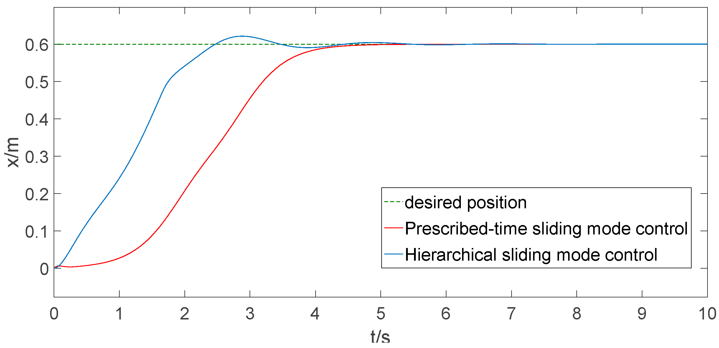
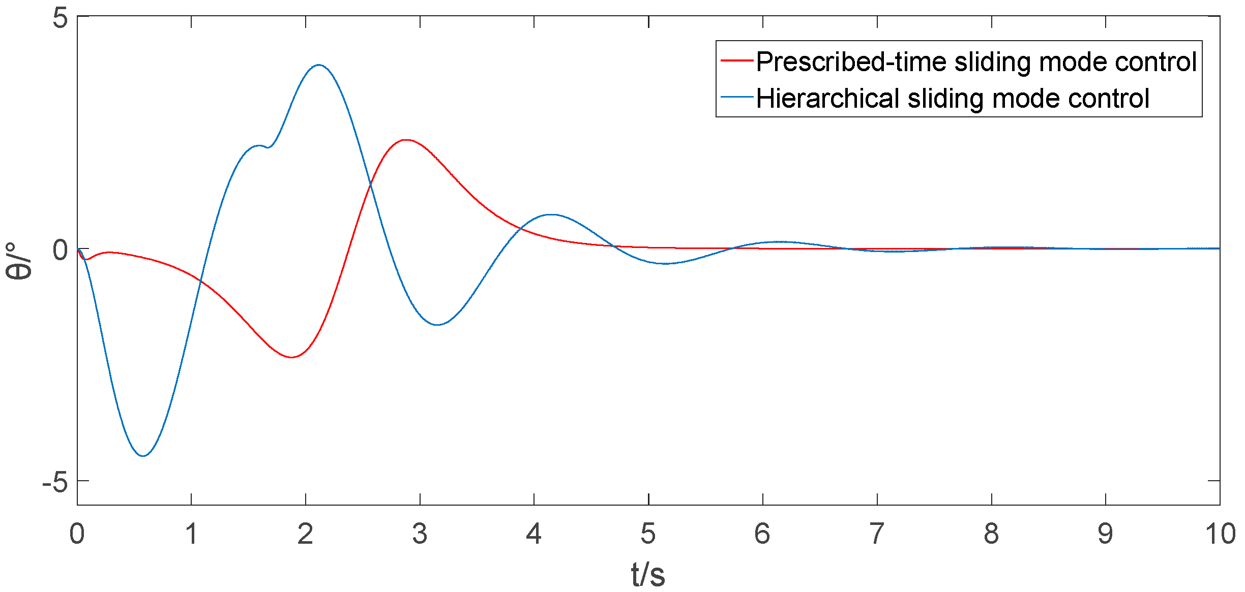
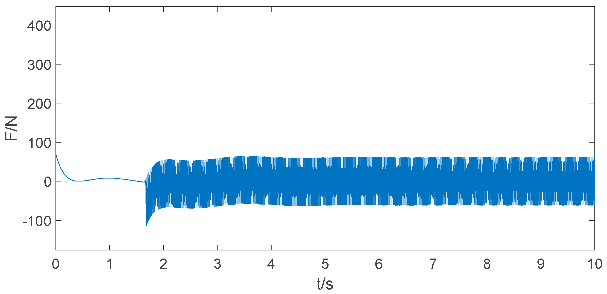
6.1. Contrast Simulation

In the present section, we validate the feasibility of the prescribed-time positioning and anti-swing controller designed herein through simulations. Additionally, we compare its performance with the hierarchical sliding mode controller, which is designed in reference [15], and provide detailed parameter information for the controller below.
u = α c 1 e 2 + α f 1 + β c 2 e 4 + β f 2 + k 1 s + k 2 sgn ( s ) α g 1 + β g 2 ,
in the equation mentioned above, e 2 = x ˙ 1 x ˙ 1 d , e 4 = x ˙ 3 x ˙ 3 d
f 1 = m l θ ˙ 2 sin θ + m g sin θ cos θ M + m sin 2 θ g 1 = 1 M + m sin 2 θ f 2 = ( M + m ) g sin θ + m l θ ˙ 2 sin θ cos θ ( M + m sin 2 θ ) l g 2 = cos θ ( M + m sin 2 θ ) l
The parameters of the controller in reference [15] are as follows.
c 1 = 3 ,   c 2 = 0.01 ,   α = 2 ,   β = 1.4 ,   k 1 = 0.1 ,   k 2 = 2 .
To demonstrate that the designed controller ensures the bridge crane achieves trolley positioning and load anti-sway within a prescribed time, we constructed a simulation model of the bridge crane control system using MATLAB 2018b with the same system parameters. Firstly, the bridge crane’s positioning and anti-swing time need to be verified. Secondly, when the bridge crane is being transported, it is desired to have minimal overshoot of the trolley position to avoid derailment accidents caused by the trolley running beyond the maximum track length. Furthermore, excessive swing angle of the load during transportation may result in load detachment or collisions with surrounding equipment, leading to safety accidents. Therefore, a minimal load swing angle is desired during the load transportation process. Consequently, this section considers convergence time and overshooting amount as the controller performance evaluation criteria.
The parameters of a given bridge crane system are M = 25 kg, m = 8 kg, l = 1.2 m, g = 9.8   m / s 2 . The controller designed in this paper has the following parameters: α 0 = 0.02 , α 1 = 0.05 , α 2 = 0.06 , β = 0.07 , T 0 = 1 , T 1 = 1 , T 2 = 1 , T a = 3 ; the reference trajectory [34] was selected as x d = p d 2 + 1 2 k 2 ln ( cosh ( k 1 t ε ) cosh ( k 1 t ε k 2 p d ) ) . In the formula, p d = 0.6   m is the position at which the trolley is expected to arrive, where k 1 = 1.33 , k 2 = 0.55 and ε = 3 are the trajectory parameters. The comparison results from the simulation are illustrated in Figure 3, Figure 4, Figure 5 and Figure 6.
Through the simulation and analysis of data, the controller designed for this article ensures that the bridge crane system achieves trolley positioning and load anti-swinging within a prescribed time of 6 s. That means that the controller designed for this article can adjust the controller parameters to preset bridge crane’s desired positioning and anti-swing time. Furthermore, compared to reference [15], the proposed controller in this paper decreases the trolley position overshoot by 3.6% (see Figure 3), reduces the load swing time by 3 s, and decreases the swing angle magnitude by 46% (see Figure 4). In the transportation process of the bridge crane, excessive overshoot in the trolley position can lead to accidents. Therefore, it is often desired to minimize the overshoot in the trolley position, aiming for it to be zero. Additionally, it is important to keep to the minimum possible load swing angle to avoid collisions with surrounding equipment. Therefore, the controller designed for this article exhibits much better control performance as compared to the hierarchical sliding mode controller designed in reference [15]. Moreover, the nonlinear sliding surface designed for this article, based on the prescribed-time theory, achieves system state convergence with damping. When the state converges to zero, the system damping increases, effectively suppressing the inherent chattering problem of the sliding mode controller (see Figure 5 and Figure 6).

6.2. Simulation under Different Prescribed Time

In this subsection, to validate that the prescribed-time sliding mode controller can adjust the bridge crane system positioning and anti-swing time by modifying the controller parameters while maintaining other parameters constant, the reaching time parameter T a of the sliding mode surface s 3 is configured to 2 s, 3 s, and 4 s, respectively. Consequently, the bridge crane positioning and anti-swing time are adjusted to 5 s, 6 s, and 7 s, respectively. The simulation outcomes for varying prescribed times are illustrated in Figure 7, Figure 8, Figure 9, Figure 10, Figure 11, Figure 12 and Figure 13.
The simulation results indicate that the designed controller can achieve the control objectives within the prescribed time when the bridge crane positioning and anti-swing time are set to 5 s, 6 s, and 7 s, respectively, by adjusting the controller parameters (see Figure 7, Figure 8, Figure 9, Figure 10, Figure 11, Figure 12 and Figure 13). This validates that the designed controller can preset the bridge crane positioning and anti-sway time.

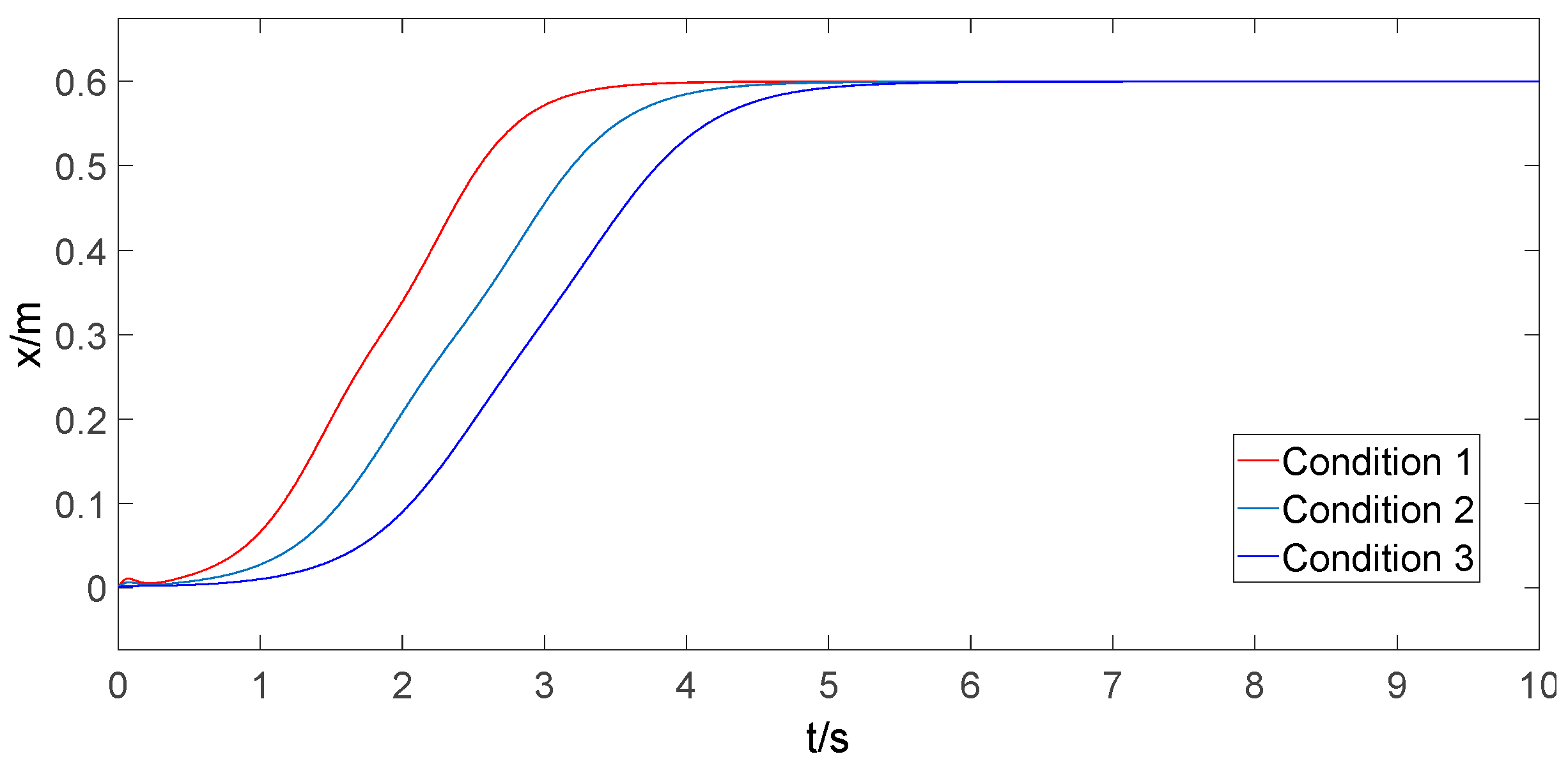
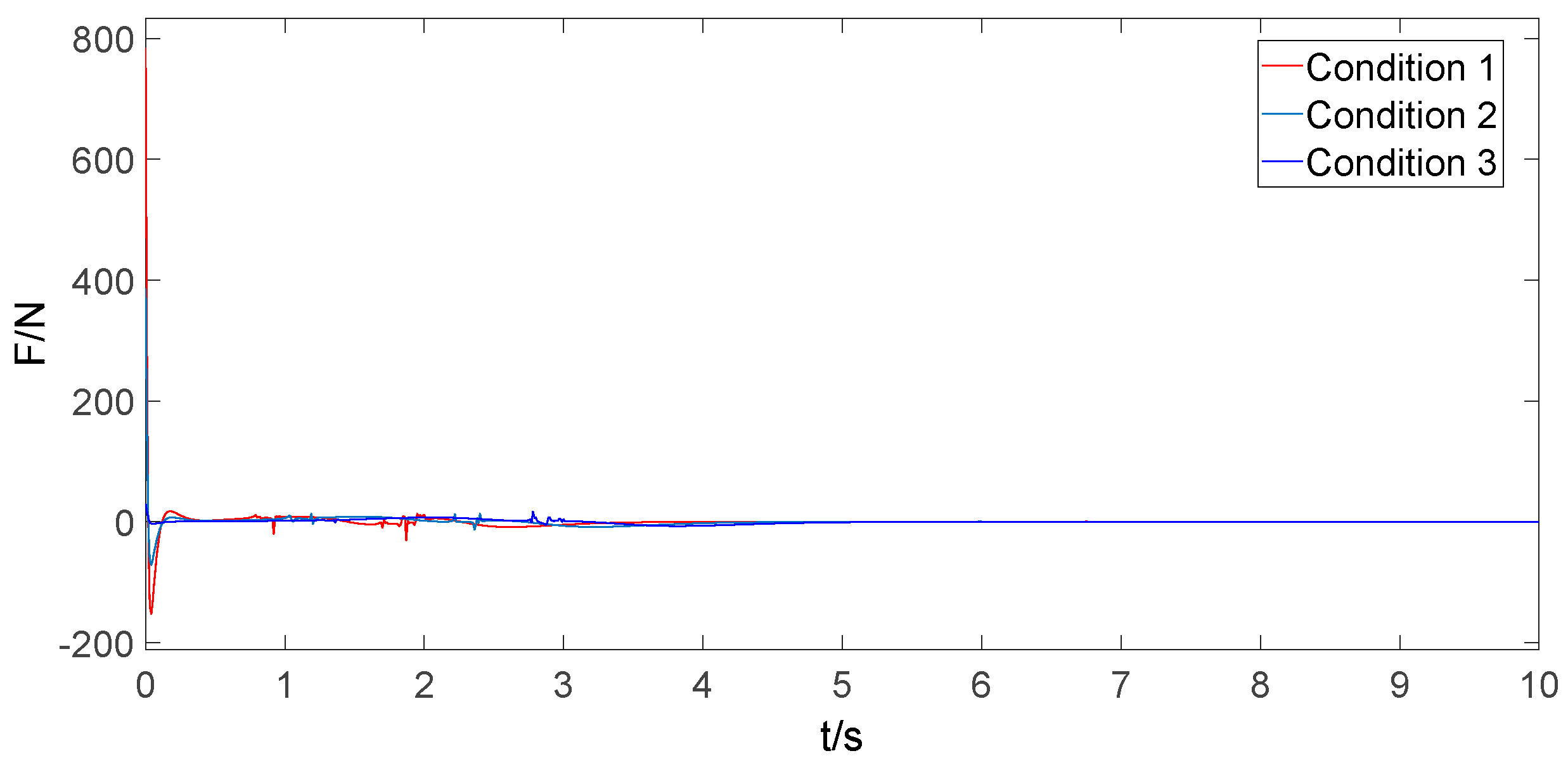
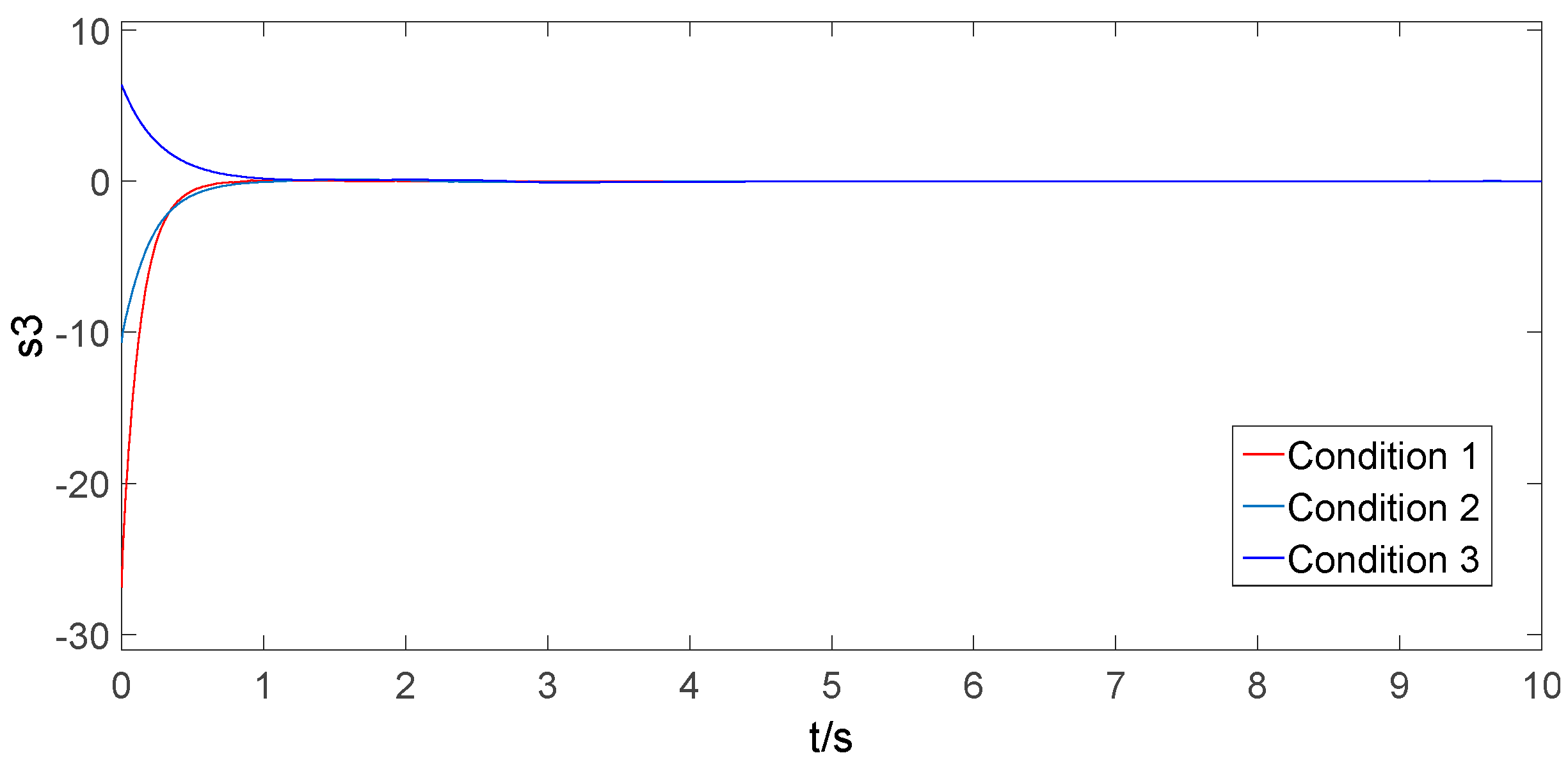
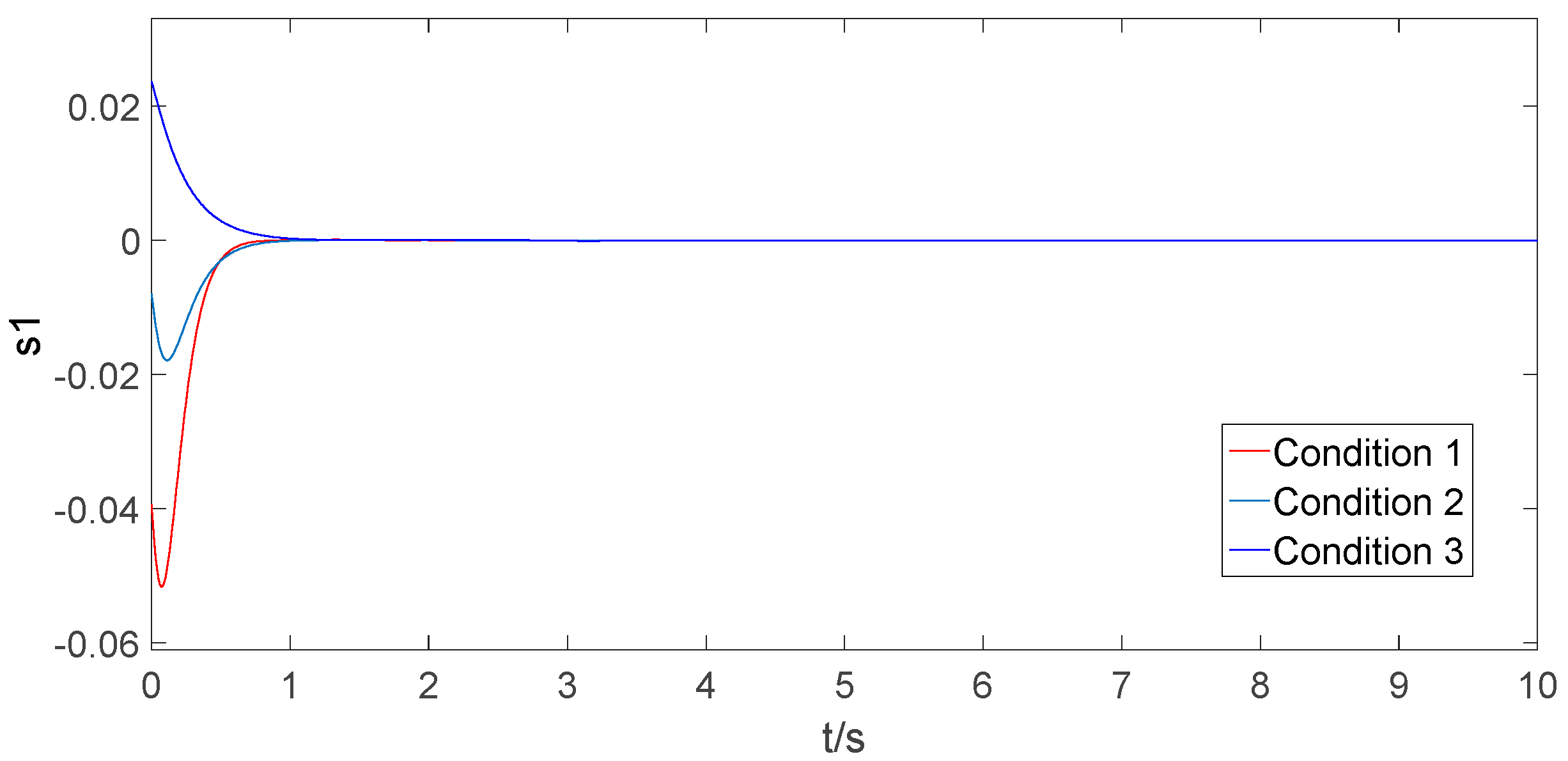
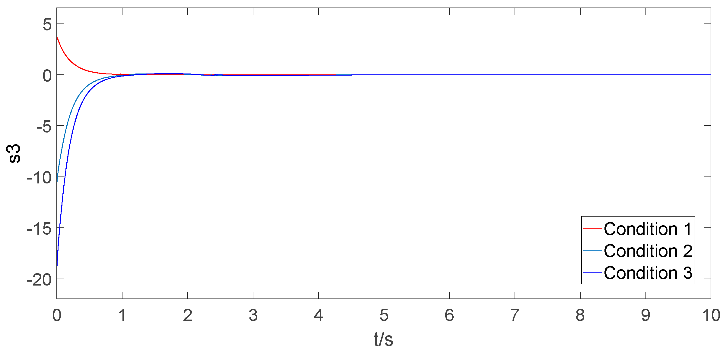
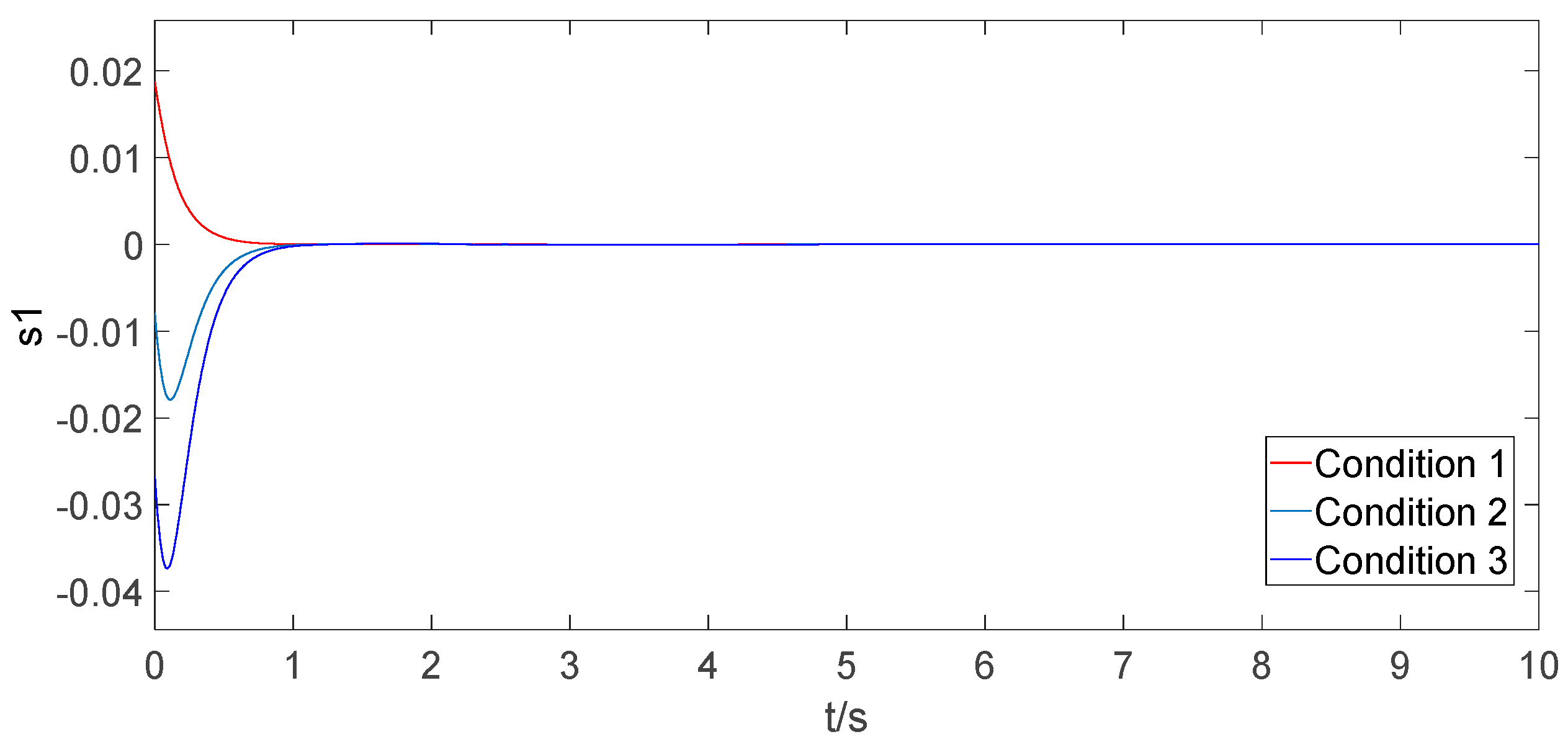
6.3. Simulation under Different Initial Conditions

In the previous section, a set of experiments was conducted to confirm the feasibility of the designed prescribed-time sliding mode controller. However, because bridge cranes vary in load mass, cable length, and transport distance for each material transport, the designed controller needs to achieve the specified time positioning and anti-sway under various conditions. In this section, while keeping the controller parameters constant, the experimental conditions are modified to verify the ability of the designed controller to achieve positioning and anti-swing within the prescribed time under different conditions. Three sets of experimental conditions are set, as shown in Table 2.
To better demonstrate that the designed controller can achieve the control objectives under different conditions, the control performance is analyzed by simulating the trolley trajectory, load swing angle, and the convergence trajectories of the sliding mode surface at all levels (see Figure 14, Figure 15, Figure 16, Figure 17, Figure 18, Figure 19 and Figure 20).
The simulation outcomes indicate that under various conditions, the proposed prescribed-time sliding mode controller ensures that the bridge crane system achieves trolley positioning and load anti-swinging within a prescribed time (see Figure 14, Figure 15, Figure 16, Figure 17, Figure 18, Figure 19 and Figure 20).

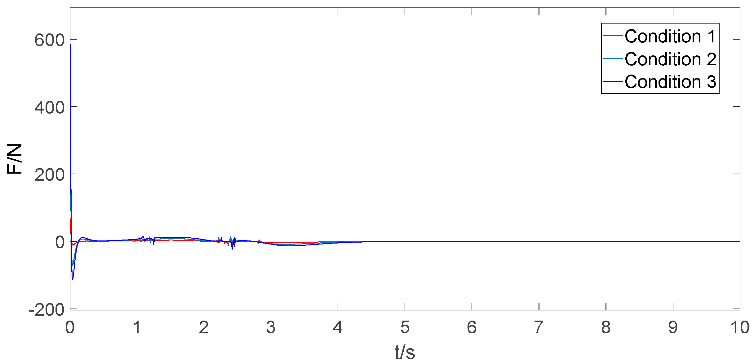
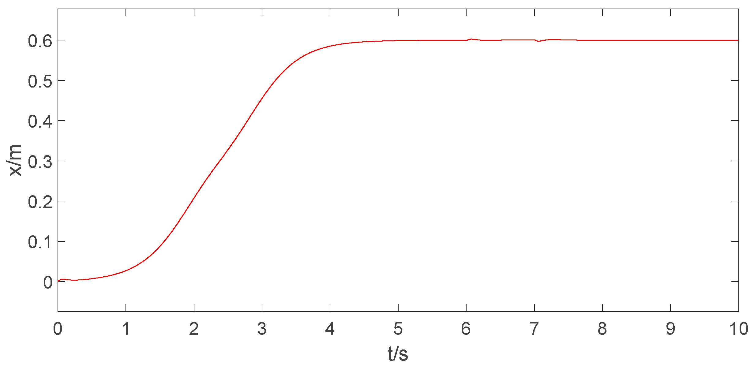
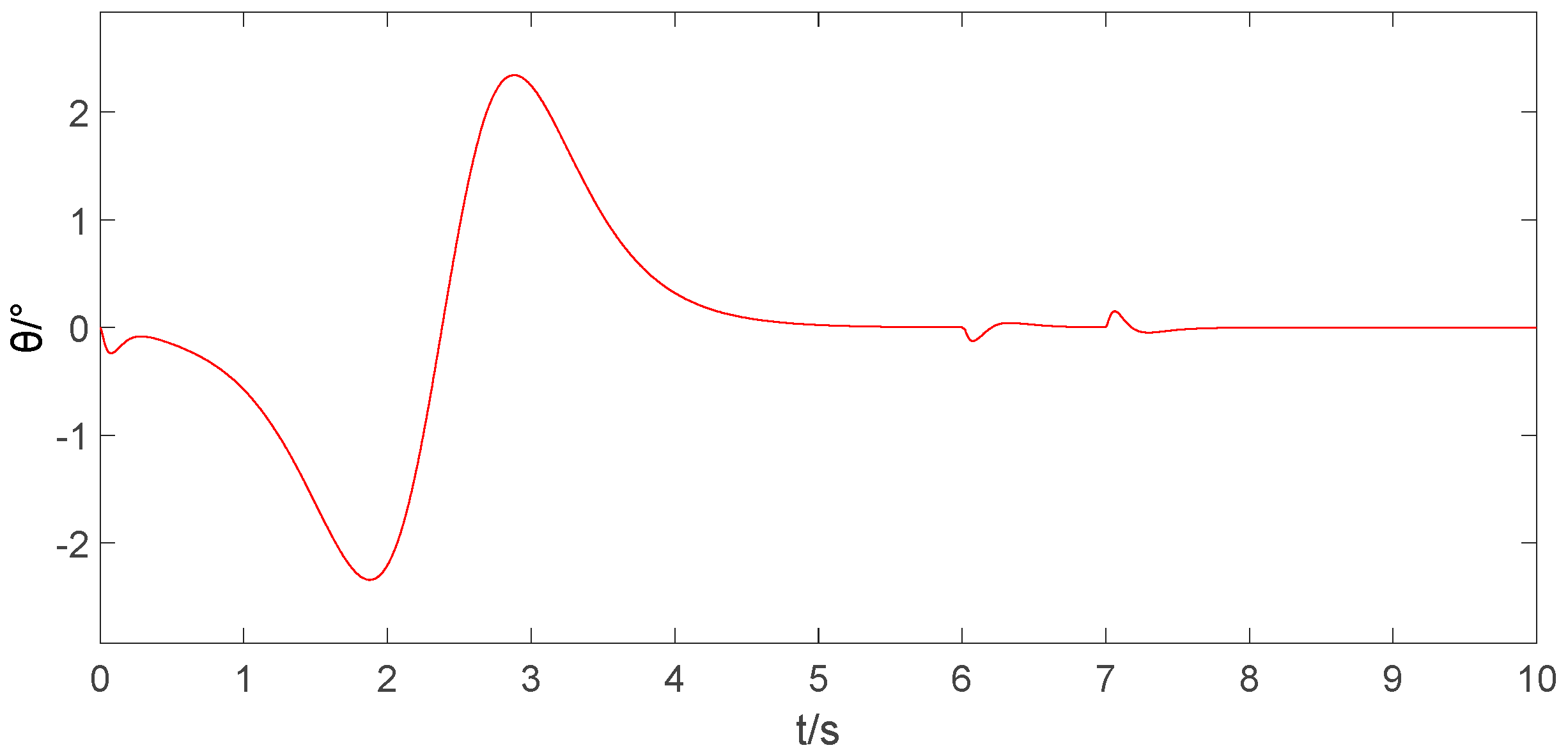
6.4. Robustness Test

The bridge crane is subject to wind and other external disturbances during the load transfer process, so the designed controller needs to have high robustness. To verify the robustness of the controller proposed for this article, a step signal with an amplitude of 300 N was introduced at the input of the model during the simulation period of 6–7 s to simulate the effect of external disturbances during crane operation.
Through the robustness testing simulation, it can be observed that the controller designed in this paper exhibits strong robustness. When the system is subjected to external disturbances and the system state deviates from the equilibrium (see Figure 21 and Figure 22), the designed controller immediately generates opposing forces to compensate for the disturbance (see Figure 23) and bring the state variables back to equilibrium. As a result, the trolley position and the load swing angle experience only minor changes and can quickly recover to a balanced state.

7. Conclusions

The prescribed-time positioning and anti-swing controller are designed to ensure that the crane can realize the rapid transfer of materials and the designable problem of positioning and anti-swing time. Compared with the existing control methods, the designed prescribed-time positioning and anti-swing controller reduce positioning overshoot by 3.6%, decrease the anti-swing time of the load by 3 s, and reduce the swing angle amplitude by 46%; this offers faster anti-swing speeds and reduced overshoot, which can be set by adjusting the controller parameters for the bridge crane system’s positioning and swing elimination time. The feasibility of the controller was confirmed through theoretical analysis and simulation. Different positioning and anti-swing time were achieved by modifying the controller parameters, which demonstrated the ability to use controller parameters to preset the bridge crane system positioning and anti-swing time. After several sets of tests under different conditions, it is confirmed that the variation in the internal parameters of the system does not affect the performance of the controller designed for this article. Although there are disturbances during the simulation, the system is able to quickly recover to a stable state, which verifies the robustness of the controller.
This paper successfully applied the theory of prescribed-time stability to the design of positioning and anti-swing time in the underactuated two-dimensional bridge crane system. Three-dimensional bridge crane systems have more complex dynamic characteristics than two-dimensional systems, posing greater challenges in controller design. Additionally, more performance metrics can be incorporated into the controller design process for control performance optimization. Therefore, future research will focus on the design of positioning and anti-swing time in three-dimensional bridge crane systems and the inclusion of additional performance metrics in the controller design process.

Author Contributions

Conceptualization, Y.F. and C.G.; investigation, Y.F. and C.G.; writing—original draft, Y.F. and H.Z.; writing—review and editing, Y.F. and H.Z. All authors have read and agreed to the published version of the manuscript.

Funding

This research was funded by the National Natural Science Foundation of China Youth Program (62003201).

Data Availability Statement

The complete research data produced within the study are contained within this article.

Conflicts of Interest

The authors declare no conflict of interest.

References

  1. Wahrburg, A.; Jurvanen, J.; Niemelä, M.; Holmberg, M. On reference trajectory generation for overhead crane travel movements. at-Automatisierungstechnik 2022, 70, 300–311. [Google Scholar] [CrossRef]
  2. Li, G.; Ma, X.; Li, Z.; Li, Y. Optimal trajectory planning strategy for underactuated overhead crane with pendulum-sloshing dynamics and full-state constraints. Nonlinear Dyn. 2022, 109, 815–835. [Google Scholar] [CrossRef]
  3. Wu, Q.; Sun, N.; Wang, X. Equivalent Rope Length-Based Trajectory Planning for Double Pendulum Bridge Cranes with Distributed Mass Payloads. Actuators 2022, 11, 25. [Google Scholar] [CrossRef]
  4. Li, H.; Hui, Y.; Ma, J.; Wang, Q.; Zhou, Y.; Wang, H. Research on Variable Universe Fuzzy Multi-Parameter Self-Tuning PID Control of Bridge Crane. Appl. Sci. 2023, 13, 4830. [Google Scholar] [CrossRef]
  5. Li, H.; Hui, Y.B.; Wang, Q.; Wang, H.-X.; Wang, L.-J. Design of Anti-Swing PID Controller for Bridge Crane Based on PSO and SA Algorithm. Electronics 2022, 11, 3143. [Google Scholar] [CrossRef]
  6. Yu, Z.; Niu, W. Flatness-Based Backstepping Antisway Control of Underactuated Crane Systems under Wind Disturbance. Electronics 2023, 12, 244. [Google Scholar] [CrossRef]
  7. Le, H.X.; Kim, T.D.; Hoang, Q.D.; Van Pham, M.; Van Nguyen, T.; Van Pham, H.; Do, D.M. Adaptive fuzzy backstepping hierarchical sliding mode control for six degrees of freedom overhead crane. Int. J. Dyn. Control 2022, 10, 2174–2192. [Google Scholar] [CrossRef]
  8. Pham, H.V.; Hoang, Q.D.; Pham, M.V.; Do, D.M.; Phi, N.H.; Hoang, D. An Efficient Adaptive Fuzzy Hierarchical Sliding Mode Control Strategy for 6 Degrees of Freedom Overhead Crane. Electronics 2022, 11, 713. [Google Scholar] [CrossRef]
  9. Zhu, X.; Xu, W. Nonlinear time-varying sliding mode synchronous control of double-lift overhead cranes under unknown disturbances. Trans. Inst. Meas. Control 2023, 45, 181–194. [Google Scholar] [CrossRef]
  10. Guo, Q.; Chai, L.; Liu, H. Anti-swing sliding mode control of three-dimensional double pendulum overhead cranes based on extended state observer. Nonlinear Dyn. 2022, 111, 391–410. [Google Scholar] [CrossRef]
  11. Wang, T.L.; Tan, N.L.; Zhang, X.W.; Li, G.; Su, S.; Zhou, J.; Qiu, J.; Wu, Z.; Zhai, Y.; Labati, R.D.; et al. A Time-Varying Sliding Mode Control Method for Distributed-Mass Double Pendulum Bridge Crane with Variable Parameters. IEEE Access 2021, 9, 75981–75992. [Google Scholar] [CrossRef]
  12. Wen, T.C.; Fang, Y.C.; Lu, B. Neural network-based adaptive sliding mode control for underactuated dual overhead cranes suffering from matched and unmatched disturbances. Auton. Intell. Syst. 2022, 2, 1. [Google Scholar] [CrossRef]
  13. Wang, L.Q.; Wu, X.Q.; Lei, M.Z. Feedforward-control-based nonlinear control for overhead cranes with matched and unmatched disturbances. J. Mech. Eng. Sci. 2022, 236, 5785–5795. [Google Scholar] [CrossRef]
  14. Chen, Q.R.; Cheng, W.M.; Liu, J.H.; Du, R. Partial state feedback sliding mode control for double-pendulum overhead cranes with unknown disturbances. J. Mech. Eng. Sci. 2022, 236, 3902–3911. [Google Scholar] [CrossRef]
  15. Le, H.X.; Le, A.V.; Nguyen, L. Adaptive fuzzy observer based hierarchical sliding mode control for uncertain 2D overhead cranes. Cyber-Phys. Syst. 2019, 5, 191–208. [Google Scholar] [CrossRef]
  16. Wang, T.L.; Zhou, J.; Wu, Z.Q.; Liu, R.J.; Zhang, J.L.; Liang, Y.Y. A Time-Varying PD Sliding Mode Control Method for the Container Crane Based on a Radial-Spring Damper. Electronics 2022, 11, 3543. [Google Scholar] [CrossRef]
  17. Yang, W.L.; Chen, J.Y.; Xu, D.Z.; Yan, X. Hierarchical global fast terminal sliding-mode control for a bridge travelling crane system. IET Control Theory Appl. 2021, 15, 814–828. [Google Scholar] [CrossRef]
  18. Xin, W.; Liu, C.T.; He, Z.X. A Parameters Adaptive Non-Singular Terminal Sliding Mode Control Method for Overhead Crane System. Int. J. Front. Eng. Technol. 2022, 4, 42–48. [Google Scholar]
  19. Nguyen, V.T.; Yang, C.H.; Du, C.L.; Liao, L. Design and implementation of finite time sliding mode controller for fuzzy overhead crane system. ISA Trans. 2019, 124, 374–385. [Google Scholar] [CrossRef]
  20. Gu, X.T.; Zhou, H.; Hong, M.Q.; Guo, Y. Adaptive hierarchical sliding mode controller for tower cranes based on finite time disturbance observer. Int. J. Adapt. Control Signal Process. 2022, 36, 2319–2340. [Google Scholar] [CrossRef]
  21. Wu, X.Q.; Xu, K.X.; He, X.X. Disturbance-observer-based nonlinear control for overhead cranes subject to uncertain disturbances. Mech. Syst. Signal Process. 2020, 139, 106631. [Google Scholar] [CrossRef]
  22. Zhang, M.H. Finite-time model-free trajectory tracking control for overhead cranes subject to model uncertainties, parameter variations and external disturbances. Trans. Inst. Meas. Control 2019, 41, 3516–3525. [Google Scholar] [CrossRef]
  23. Zhang, M.H.; Zhang, Y.F.; Cheng, X.G. Finite-Time Trajectory Tracking Control for Overhead Crane Systems Subject to Unknown Disturbances. IEEE Access 2019, 7, 55974–55982. [Google Scholar] [CrossRef]
  24. Wu, X.F.; Qian, J.Y. Fixed-time Tracking Control of Underactuated Overhead Cranes. In Proceedings of the 30th Chinese Control and Decision Conference, Shenyang, China, 9–11 June 2018; pp. 852–857. [Google Scholar]
  25. Khanzadeh, A.; Pourgholi, M. A novel continuous time-varying sliding mode controller for robustly synchronizing non-identical fractional-order chaotic systems precisely at any arbitrary pre-specified time. Nonlinear Dyn. 2016, 86, 543–558. [Google Scholar] [CrossRef]
  26. Liu, Y.F.; Zhao, Y.; Shi, Z.K.; Wei, D. Specified-time containment control of multi-agent systems over directed topologies. IET Control Theory Appl. 2017, 11, 576–585. [Google Scholar] [CrossRef]
  27. Wei, C.S.; Luo, J.J.; Yin, Z.Y.; Yuan, J. Leader-following consensus of second-order multi-agent systems with arbitrarily appointed-time prescribed performance. IET Control Theory Appl. 2018, 12, 2276–2286. [Google Scholar] [CrossRef]
  28. Wang, J.G.; Luo, X.Y.; Li, X.L.; Guan, X. Specified-Time Bearing-Based Formation Control of Multi-Agent Systems via a Dynamic Gain Approach. J. Frankl. Inst. 2018, 355, 8619–8641. [Google Scholar] [CrossRef]
  29. Zhao, Y.; Liu, Y.F.; Wen, G.H.; Ren, W.; Chen, G. Designing Distributed Specified-Time Consensus Protocols for Linear Multiagent Systems Over Directed Graphs. IEEE Trans. Automat. Control 2019, 64, 2945–2952. [Google Scholar] [CrossRef]
  30. Liu, M.M.; Shao, X.D.; Ma, G.F. Appointed-time fault-tolerant attitude tracking control of spacecraft with double-level guaranteed performance bounds. Aerosp. Sci. Technol. 2019, 92, 337–346. [Google Scholar] [CrossRef]
  31. Wu, X.J.; Zheng, W.Y.; Zhou, X.X.; Shao, S. Adaptive dynamic surface and sliding mode tracking control for uncertain QUAV with time-varying load and appointed-time prescribed performance. J. Frankl. Inst. 2021, 358, 4178–4208. [Google Scholar] [CrossRef]
  32. Zhang, L.; Liu, J.F.; Cui, N.G. Backstepping control for a two-link manipulator with appointed-time convergence. ISA Trans. 2021, 128, 208–219. [Google Scholar] [CrossRef] [PubMed]
  33. Liu, D.T.; Yi, J.Q.; Zhao, D.B.; Wang, W. Adaptive sliding mode fuzzy control for a two-dimensional overhead crane. Mechatronics 2005, 15, 505–522. [Google Scholar] [CrossRef]
  34. Fang, Y.; Ma, B.; Wang, P.; Zhang, X. A Motion Planning-Based Adaptive Control Method for an Underactuated Crane System. IEEE Trans. Control Syst. Technol. 2012, 20, 241–248. [Google Scholar] [CrossRef]
Figure 1. The 2D underactuated bridge crane.
Electronics 13 00219 g001
Figure 2. Research approach.
Electronics 13 00219 g002
Figure 3. Trolley position trajectory.
Electronics 13 00219 g003
Figure 4. Load swing angle curve.
Electronics 13 00219 g004
Figure 5. Prescribed-time sliding mode control law.
Electronics 13 00219 g005
Figure 6. Hierarchical sliding mode control law.
Electronics 13 00219 g006
Figure 7. Trolley position trajectory under different prescribed time.
Electronics 13 00219 g007
Figure 8. Load swing angle curve under different prescribed time.
Electronics 13 00219 g008
Figure 9. Control law under different prescribed time.
Electronics 13 00219 g009
Figure 10. The sliding surface s3 convergence trajectory under different prescribed time.
Electronics 13 00219 g010
Figure 11. The sliding surface s2 convergence trajectory under different prescribed time.
Electronics 13 00219 g011
Figure 12. The sliding surface s1 convergence trajectory under different prescribed time.
Electronics 13 00219 g012
Figure 13. The sliding surface s0 convergence trajectory under different prescribed time.
Electronics 13 00219 g013
Figure 14. Trolley position trajectory under different conditions.
Electronics 13 00219 g014
Figure 15. Load swing angle curve under different conditions.
Electronics 13 00219 g015
Figure 16. Control law under different conditions.
Electronics 13 00219 g016
Figure 17. The sliding surface s3 convergence trajectory under different conditions.
Electronics 13 00219 g017
Figure 18. The sliding surface s2 convergence trajectory under different conditions.
Electronics 13 00219 g018
Figure 19. The sliding surface s1 convergence trajectory under different conditions.
Electronics 13 00219 g019
Figure 20. The sliding surface s0 convergence trajectory under different conditions.
Electronics 13 00219 g020
Figure 21. Trolley position trajectory after adding interference.
Electronics 13 00219 g021
Figure 22. Load swing angle curve after adding interference.
Electronics 13 00219 g022
Figure 23. Control law after adding interference.
Electronics 13 00219 g023
Table 1. Parameter definition.
SymbolsPhysical MeaningUnit
M Trolley masskg
m Load masskg
l Cable lengthm
x Trolley positionm
θ Load swing anglerad
F Driving forceN
g Gravitational acceleration m / s 2
Table 2. Different experimental conditions.
ConditionLoad MassCable LengthTransit Distance
Condition 15 kg1 m0.3 m
Condition 28 kg1.2 m0.6 m
Condition 310 kg0.9 m0.9 m
Disclaimer/Publisher’s Note: The statements, opinions and data contained in all publications are solely those of the individual author(s) and contributor(s) and not of MDPI and/or the editor(s). MDPI and/or the editor(s) disclaim responsibility for any injury to people or property resulting from any ideas, methods, instructions or products referred to in the content.

