Article

VerSA: Versatile Systolic Array Architecture for Sparse and Dense Matrix Multiplications

School of Electronic and Electrical Engineering, Kyungpook National University, Daegu 41566, Republic of Korea
*
Author to whom correspondence should be addressed.
Electronics 2024, 13(8), 1500; https://doi.org/10.3390/electronics13081500
Submission received: 27 February 2024 / Revised: 9 April 2024 / Accepted: 11 April 2024 / Published: 15 April 2024
(This article belongs to the Special Issue Heterogeneous and Energy-Efficient Computing Systems)

Abstract

:
A key part of modern deep neural network (DNN) applications is matrix multiplication. As DNN applications are becoming more diverse, there is a need for both dense and sparse matrix multiplications to be accelerated by hardware. However, most hardware accelerators are designed to accelerate either dense or sparse matrix multiplication. In this paper, we propose VerSA, a versatile systolic array architecture for both dense and sparse matrix multiplications. VerSA employs intermediate paths and SRAM buffers between the rows of the systolic array (SA), thereby enabling an early termination in sparse matrix multiplication with a negligible performance overhead when running dense matrix multiplication. When running sparse matrix multiplication, 256 × 256 VerSA brings performance (i.e., an inverse of execution time) improvement and energy saving by 1.21×–1.60× and 7.5–30.2%, respectively, when compared to the conventional SA. When running dense matrix multiplication, VerSA results in only a 0.52% performance overhead compared to the conventional SA.

1. Introduction

The rise of artificial intelligence (AI)-based applications has brought about a huge change in human life. One of the most important key enablers of this change is the improvement in computing power. A core operation in AI is matrix multiplication (MM). A dataflow-based architecture enables an efficient processing of matrix multiplication. The operations in dataflow architecture are mainly performed by moving the data and results through computing logic such as an arithmetic logical unit (ALU). One of the most widely used dataflow architectures to accelerate MM is a systolic array-based architecture.
Systolic arrays (SAs) are typically composed of two-dimensional processing element (PE) arrays. A PE performs a multiply-and-accumulation (MAC) operation with temporarily latching and forwarding of the inputs and/or outputs. There are three different dataflows, depending on which elements are stationary in the PE, in general SAs: input stationary, weight stationary, and output stationary. Depending on the dataflows, different elements are pinned to the PEs and then transferred throughout the PEs. The systolic arrays can efficiently execute the matrix multiplication due to the massive parallelism among the PEs, thereby enabling an abundant number of parallel MAC operations. Due to their low design complexity and satisfactory performance, SAs have been widely adopted in many industrial products such as tensor processing units (TPUs) [1,2,3].
Nonetheless, SAs often suffer from inefficiency when running sparse matrix multiplication (SpMM). Since there is no intermediate path that is directly connected to the output buffer, the ineffectual operations have no choice but to be executed throughout the datapath anyway. This causes huge latency and energy overheads when performing SpMM. To overcome this problem, many works have focused on sparsity-aware processing engines [4,5,6,7,8,9,10,11,12,13,14,15]. Though they show a significant speedup when executing SpMM, they are not appropriate for dense matrix multiplication. For example, a specialized format (e.g., a compressed sparse row (CSR)) must be used to execute SpMM [12], and it could be desirable for sparse matrices in terms of the data size and computation efficiency. However, they are still problematic for dense matrix multiplication. Due to the large metadata size of specialized formats, the data size would be rather increased when compared to a dense format (i.e., storing the matrix in a row-wise or column-wise manner without the coordinate metadata), which incurs large storage or memory overhead, as well as computation inefficiency. Even worse in typical embedded or mobile systems where accommodated hardware resources are constrained, it could be very hard to employ separate hardware accelerators for dense and sparse MMs.
In this paper, we propose VerSA, Versatile Systolic Array architecture, to accelerate both dense and sparse matrix multiplications. By providing two operation modes, i.e., sparse and dense modes, VerSA adaptively executes dense MM and SpMM in a single-hardware architecture. In the sparse mode, the model utilizes intermediate paths and buffers (IPBs) between the rows of PEs, which is designed for the early termination of SpMM by skipping ineffectual operations. In the dense mode, VerSA operates similarly as the conventional systolic array (SA) with negligible performance overhead. Our evaluation results show that our 256 × 256 VerSA architecture when running in the sparse mode shows a better performance by 1.21×–1.60× when compared to the conventional SA. Also, VerSA when running in the dense mode shows a comparable performance when compared to the conventional SA, incurring only a 0.52% performance overhead. When compared to the state-of-the-art SpMM accelerator [12], VerSA shows a better performance by 20.1×, on average, when executing various SpMM benchmark applications. The main contributions of this work can be summarized as follows:
  • We propose the VerSA architecture, which can be used for both dense and sparse matrix multiplications in a versatile manner;
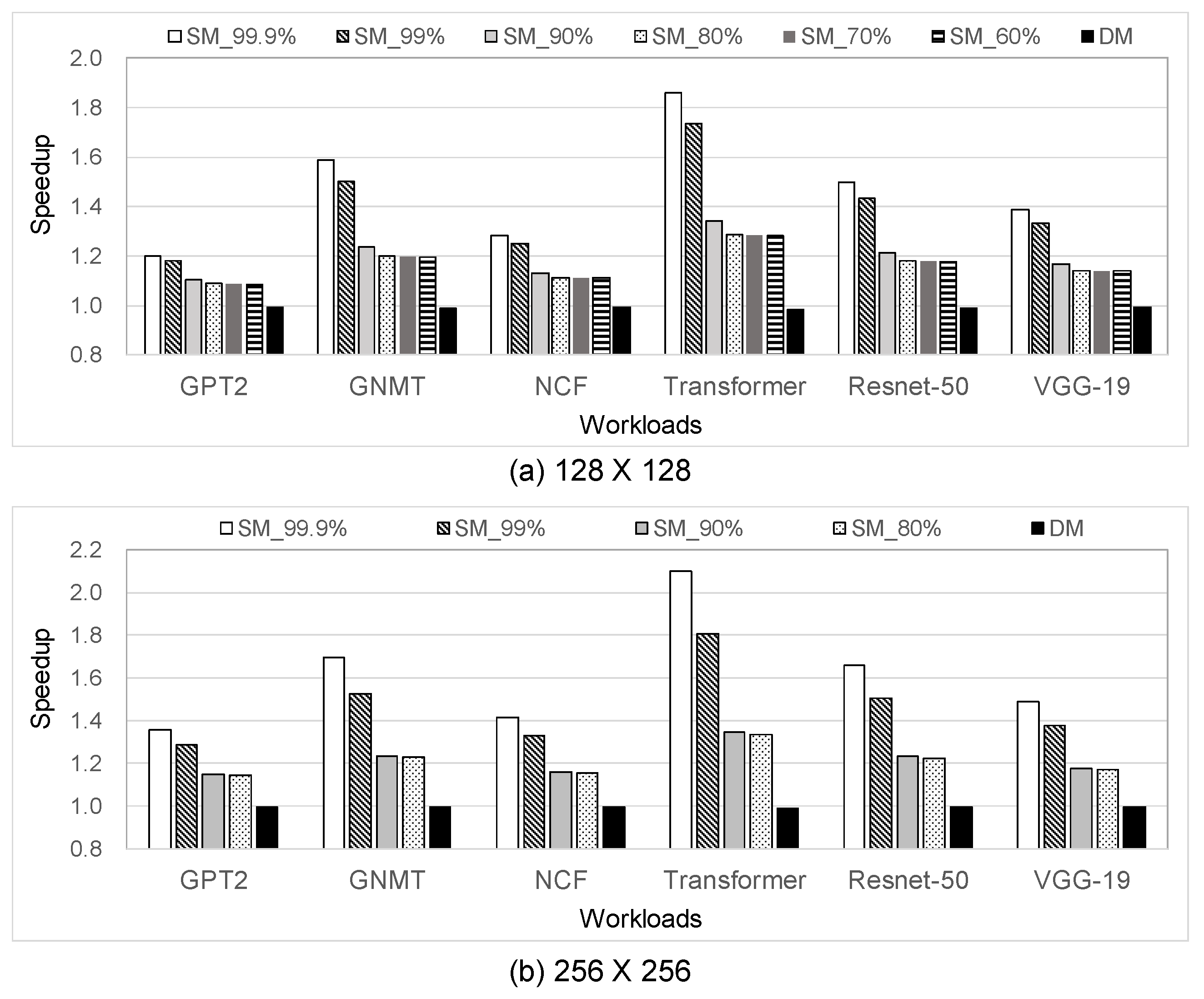
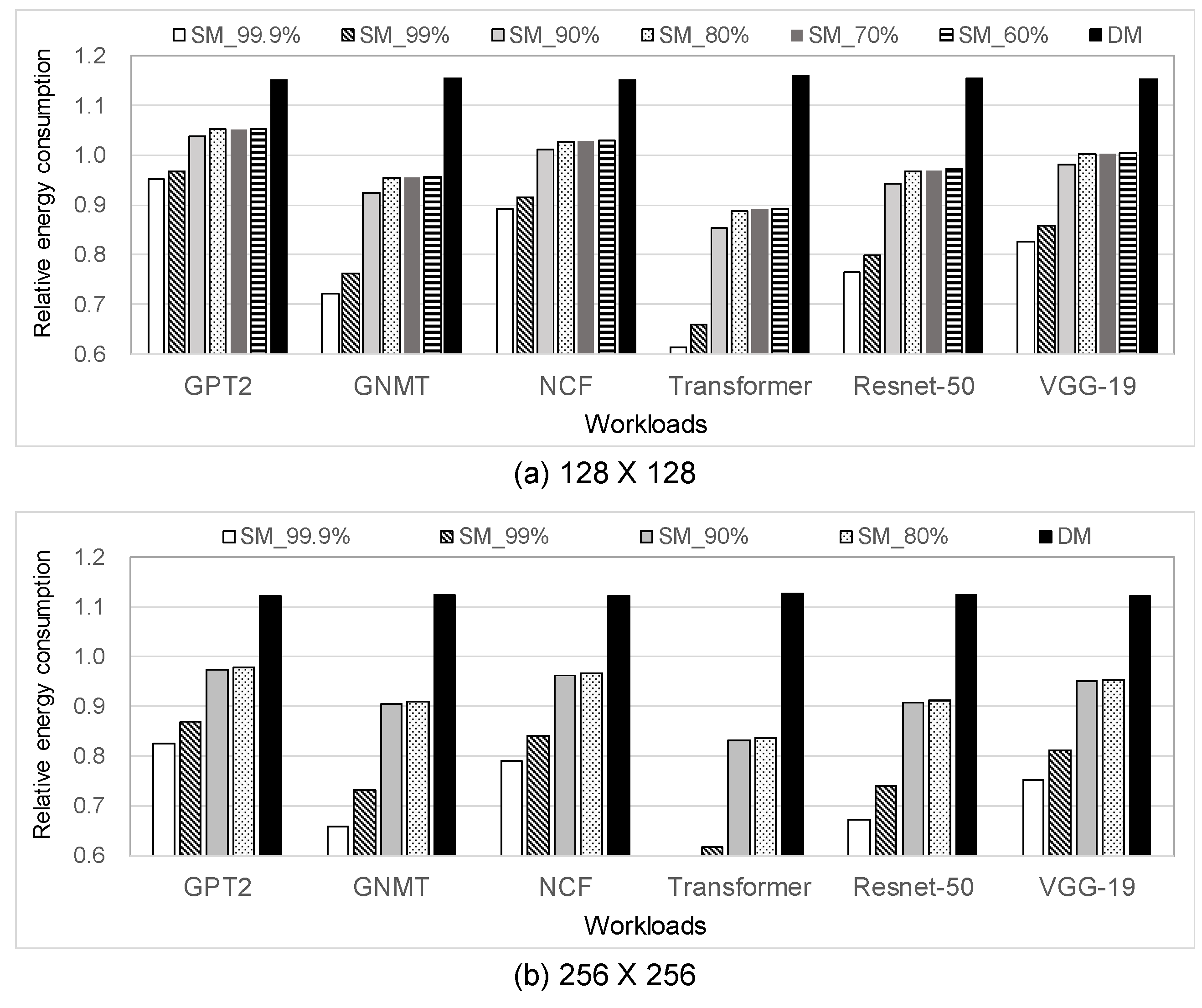
  • When executing SpMM, 256 × 256 (128 × 128) VerSA results in performance improvement and energy saving by 1.21×–1.60× (1.16×–1.45×) and 7.5–30.2% (1.6–21.3%), respectively, on average, when compared to the conventional SA;
  • When compared to the state-of-the-art SpMM accelerator, our 256 × 256 (128 × 128) VerSA shows a better performance by 20.1× (5.7×), on average, meaning that VerSA can be used for a broader range of MM applications;
  • In terms of logic synthesis results, 256 × 256 (128 × 128) VerSA architecture can be implemented with only small hardware and power overheads when compared to the conventional SA by 12.6% (14.9%) and 11.7% (14.4%), respectively.
The remainder of this paper is organized as follows. Section 2 reviews the recent literature that are closely related to our work. Section 3 explains the background for general systolic arrays and our motivation. Section 4 explains our VerSA architecture in detail. Section 5 shows our evaluation results in terms of performance and energy. Section 6 discusses the hardware and software overheads and limitations of this work. Section 7 then concludes this paper.

2. Related Works

For dense matrix multiplication, systolic arrays are widely used due to their simple yet efficient logic architecture (e.g., [1]) and the easy employment of various dataflows such as weight stationary, row stationary, input stationary, and output stationary [16]. However, conventional systolic arrays are not adequate for sparse matrix multiplication as they cannot skip ineffectual operations.
For sparse matrix multiplication supports, many works have been focused on removing the ineffectual operations from matrix multiplication [4,5,6,7,8,9,10,11,12,13,14,15]. The most widely used method is to employ a compressed format (e.g., compressed sparse row [12] or channel cyclic sparse row format [9]) for performing sparse matrix multiplication. Since the compressed format already removes many of the zero values in the operand matrices, MM operations with compressed formats also remove a large portion of the ineffectual operations. However, the compressed format often leads to a larger data size in the case of dense matrices due to the metadata size being even larger than the non-zero data. Furthermore, the compressed format is often required to be uncompressed for MAC operations. Several works have also compared the indices (e.g., the column index of the input matrix and row index of the weight matrix) of the non-zero values, and they only performed multiplications with those values [5], which are often referred to as the inner product. However, non-zero index matching often incurs a huge overhead in logic and time complexities as the density in the operand matrices increases. In [15], a flexible architecture that supports three different dataflows for sparse matrix multiplications was proposed. Though the aforementioned approach enables a flexible dataflow change within a single hardware architecture, only dataflows for sparse MM are supported.
As explained above, accelerators that are used only for sparse matrix multiplication are very hard to be employed for dense matrix multiplication due to the inefficiency of their compressed formats and dataflows, which are optimized only for sparse matrix multiplication. When compared to the related works introduced in this section, our VerSA architecture can be employed to perform both dense and sparse MMs with a unified hardware architecture. Due to its versatility, VerSA is more suitable for resource-constrained embedded systems where separate hardware accelerators for dense and sparse MMs in the system are not desirable.

3. Background and Motivation

One of the most widely used architectures for accelerating MM is a systolic array (SA), which is shown in Figure 1. The main advantages of the SA are its design simplicity and high efficiency for matrix multiplication. The conventional systolic arrays for matrix multiplication can provide three different dataflows: input stationary, weight stationary, and output stationary [17]. Assuming we perform A × B = C where A, B, and C are matrices, input, weight, and output stationary dataflows fix (i.e., preloaded and are not moved throughout the PEs) the elements in the matrix A, B, and C, respectively, in the PEs of the SA. For typical DNN applications, the weight stationary dataflow is widely used for DNN inference accelerators because the weights can be heavily reused across the batches when performing DNN inferences, which minimizes the data transfer overhead in the SA.
When performing sparse matrix multiplication (SpMM), the main disadvantage of the conventional SA is that we cannot skip ineffectual operations such as multiply-with-zero or add-with-zero. Thus, for SpMM, the conventional SA takes the same clock cycles (and the same execution time with a fixed-clock frequency) for both SpMM and dense MM. Since there is a huge opportunity in removing the ineffectual operations present in SpMM, employing the SA for SpMM may cause a huge energy waste and performance loss. On the contrary, employing the specialized hardware accelerator for SpMM could be beneficial for accelerating the matrix multiplication. For example, in [12], where a specialized hardware accelerator for SpMM was used, up to 47× (on average) speedup can be obtained when compared to the conventional SA. However, the specialized SpMM hardware can be useful only when performing SpMM as it results in even worse performance for dense matrix multiplication. As general embedded systems are resource-constrained, it would be hard to deploy both SpMM and dense MM hardware accelerators. Consequently, employing a versatile hardware accelerator that can adapt to both SpMM and dense MM would be desirable.
Based on the motivations described above, we will focus on the following design principles and considerations:
  • We will devise a novel, unified hardware architecture for efficiently executing both sparse and dense MMs;
  • For the versatility of our hardware, we will also devise appropriate hardware and software supports. We will also focus on minimizing the overhead caused from those supports.

4. VerSA Architecture

4.1. Overview

In this subsection, we briefly explain the overview of VerSA architecture. VerSA architecture consists of two parts: the hardware accelerator and software supports. VerSA hardware is built upon a general systolic array that can perform matrix multiplication. We newly introduce the intermediate paths and SRAM output buffers (IPBs) between the group of the rows (which we call the ‘subarray’ in this paper) in the SA. For software supports, we need to make the preloaded matrix (weight) in the condensed format similar to that in [7] so that we can reduce the clock cycles required for sparse MM execution. The column indices of the partial sum output matrices should also be adjusted when using a column-wise-condensed weight matrix, and it should be added by software supports when performing a blocked MM (i.e., when the size of the input or weight matrix is too large to be executed in a single systolic array or a subarray).
Figure 2 depicts the overall execution flow of the VerSA architecture (A × B = C), which is similar to the conventional SA execution flow where several steps are added for the sparse mode supports. For the dense mode, which performs dense matrix multiplication, our VerSA operates almost same as the conventional SA-based MM execution. However, the following additional steps are required for sparse mode operations: (1) pre-processing when conducting a column-wise condensing of the weights (i.e., B matrix) and (2) post-processing for adjusting the column indices of the generated partial sum matrix (i.e., the partial sum of the C matrix). Column-wise condensing has the effect of removing many of the zero-valued weights in advance. Thus, by generating and preloading the column-wise-condensed weight matrix, our hardware can skip many ineffectual operations. Figure 3 shows an example of the column-wise-condensed matrix generation. We first divide the weight matrix into multiple groups of rows so that the number of rows inside of a single group is the same as the N u m R o w s s u b a r r a y (see Table 1 for notation). For each group of rows, the matrix is condensed while maintaining the shape of each column within the group (our matrix condensing method is similar to that introduced in [7], but our method also maintains the shape of each column, which makes our hardware design less complicated.). The original column indices are also maintained for column restoration during the post-processing stage. As explained above, the partial sum matrices should also be added together when performing a blocked MM; however, it is also required for the conventional SA, meaning that our VerSA has a negligible overhead when compared to the conventional SA.

4.2. Hardware Architecture

VerSA hardware architecture is similar to conventional systolic arrays; however, the key difference is an intermediate path inside the systolic array. When performing matrix multiplication, passing the generated partial sum from the first row to the last row takes N clock cycles in the case of N × N systolic arrays. In the case of dense matrix multiplication, using the full datapath would be meaningful because most of the operations are effectual during the continuous partial sum generation (i.e., the partial sum transfer and generation from the first row to the last row). However, in the case of sparse matrix multiplication, the rows will not be fully utilized with a very high probability. In this case, we could perform an early termination of partial sum generation in the case where certain rows do not need to be used.
To reduce the clock cycles needed for passing the partial sums to the lowest row in the SA, VerSA introduces intermediate paths and SRAM output buffers between the rows in the SA. Figure 4 shows the architecture of our VerSA with intermediate paths and buffers (IPBs). Firstly, we group the adjacent rows of the SA, which is referred to as ‘subarray’ (the number of rows in a single subarray is denoted as N u m R o w s s u b a r r a y ). Between the subarrays, there is an IPB, which is composed of the intermediate output path and SRAM buffer. If we can obtain the partial sum results from the IPBs (i.e., the ones earlier than those that pass through all the PEs in the same column from the first row to the last row), then we can reduce the required clock cycles for MM operation. Table 1 summarizes the design parameters for VerSA.
The IPB consists of the output buffers and multiplexors (MUXes). To enable both dense and sparse MMs in VerSA hardware, the mode selection bit is connected to the MUXes in the IPBs. In the case of the dense mode, the partial sums from the upper (i.e., previous) subarray are selected in the MUXes and delivered to the next subarray. In this case, the subarrays are connected via the IPBs. On the contrary, in the case of the sparse mode, the zero values are selected in the MUXes of the IPBs, meaning that each subarray independently operates in the sparse mode.
Passing the IPB requires one clock cycle because the partial sums should pass through the flip-flops (FFs) inside of the IPB. Thus, for dense mode operations, we additionally require N u m I P B clock cycles in comparison to the conventional SA, where N u m I P B is the total number of the IPBs in the VerSA. Since the main goal of VerSA is to enable both dense and sparse MM executions within a single SA, there can be a negligible performance overhead from the additional clock cycles when considering the performance gain from the sparse mode operations. In the case of the sparse mode, the subarrays operate separately (i.e., operate in parallel). Thus, the number of the required clock cycles for passing the partial sums to the output buffer in the IPBs or the last output buffer can be reduced to N u m R o w s s u b a r r a y + 1 (one additional clock cycle is for the IPB). Early termination in the sparse mode could be performed by using a special purpose control signal that notifies the timing of the termination in the hardware accelerator. With the given input matrix (i.e., the A matrix) dimension, condensed weight matrix (i.e., the condensed B matrix) dimension, and the hardware design parameters shown in Table 1, the required clock cycles can be calculated, which enables an early termination that is achieved by counting the executed clock cycles and comparing it with the required clock cycles.

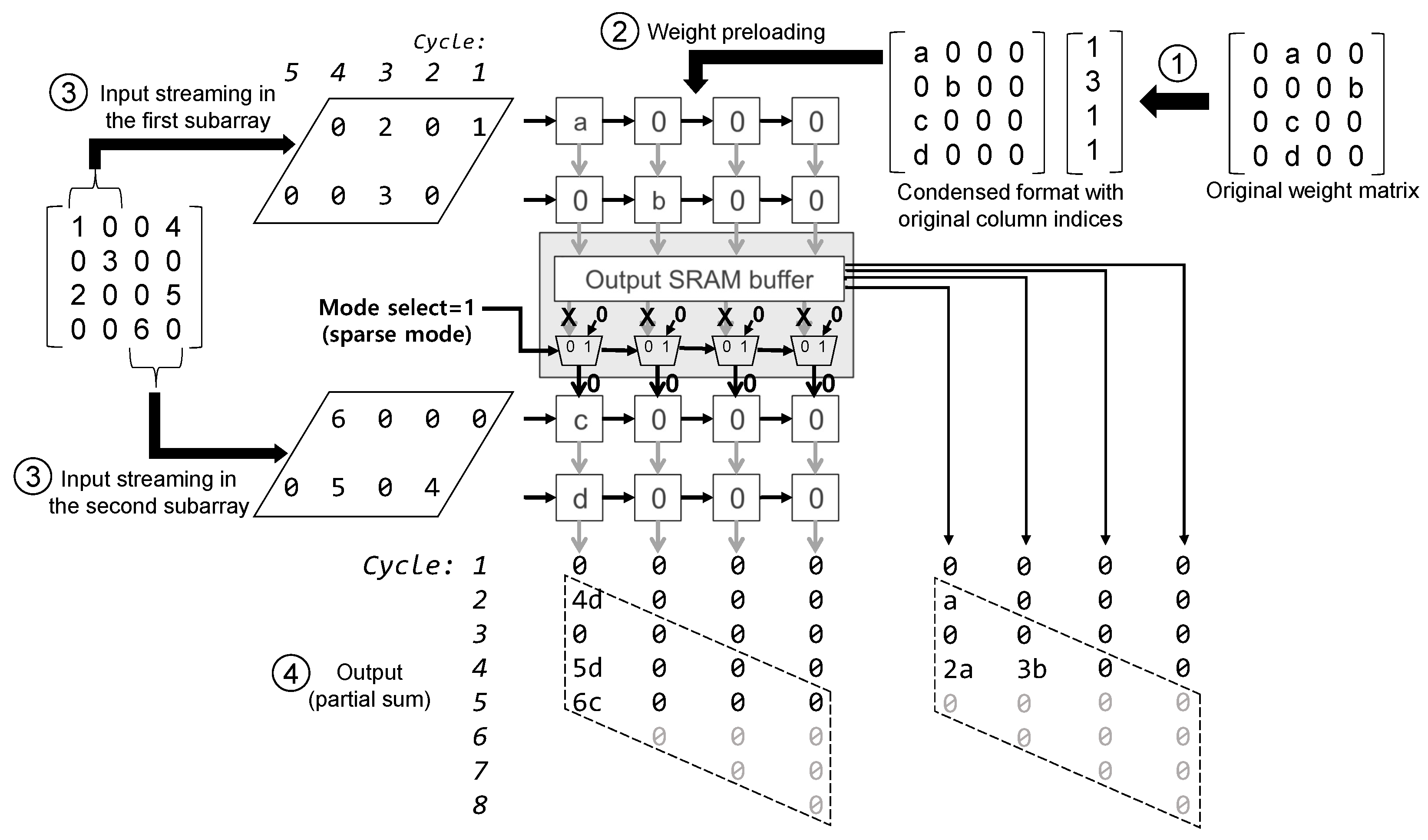
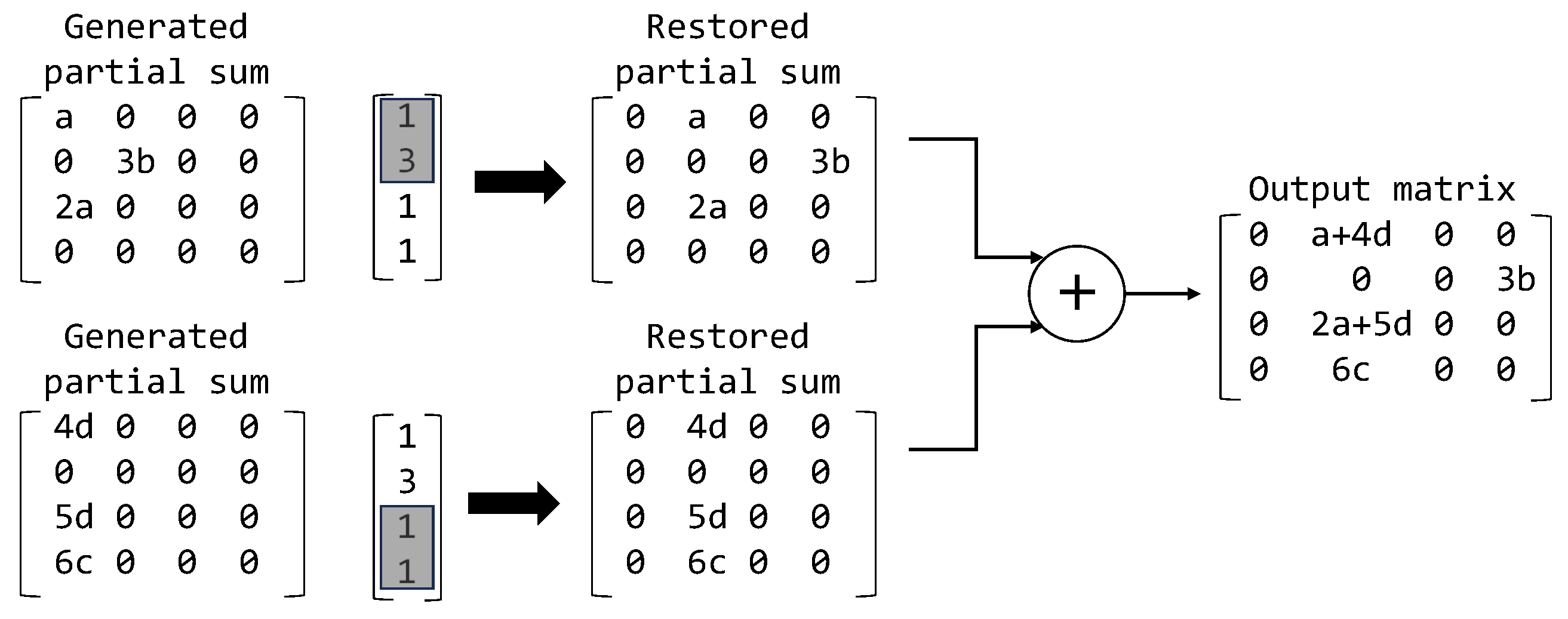
4.3. An Example of the Sparse and Dense Mode Operations

In the following subsections, we explain how the sparse and dense mode operations are performed in detail.

4.3.1. Sparse Mode Operations

In the sparse mode, each subarray can operate independently. To accomplish it, the IPBs between the subarrays select zero values in the MUXes. In the case of the conventional systolic array, the N-th row in the SA starts the input streaming after N clock cycles after the first row input streaming begins. On the contrary, the subarrays in VerSA accept the input streaming independently, as shown in Figure 5. Assuming that there are N u m R o w s s u b a r r a y rows in a single subarray, where N u m s u b a r r a y subarrays exist in the SA, the input streaming of the K-th row within each subarray starts at K-th clock cycles. In other words, N u m s u b a r r a y rows in the SA will begin the input streaming at the same clock cycle.
Figure 5 demonstrates an example of the sparse mode operation of VerSA. In this example, we use the design parameters with N u m R o w s t o t a l = 4, N u m R o w s s u b a r r a y = 2, N u m s u b a r r a y = 2, and N u m I P B = 1. For the sparse mode operation, we first perform column-wise matrix condensing (Figure 5 ➀). The weight matrix is then preloaded (i.e., with a weight stationary dataflow) to the SA (Figure 5 ➁). When performing the matrix multiplication, the input matrix is streamed to the subarrays (Figure 5 ➂). As shown in Figure 5, the subarrays operate independently as the MUXes in the IPB forcibly make the partial sum input as zero (i.e., where zero is selected in the MUXes). After the MAC operations are performed in the PEs, the outputs or partial sums are generated from the IPB and the last output buffer (Figure 5 ➃). Since the subarrays operate independently, the outputs are also generated simultaneously from each subarray.
Since we convert the weight matrix into a condensed format, the column indices of the partial sum matrices must also be restored to the original indices before the summation among the partial sums. Figure 6 demonstrates the restoration of the partial sum matrices and summation, thereby generating the final output matrix. By referring to the original column indices, which are stored during the matrix condensing, the column indices of the partial sums can also be restored to generate the final output matrix.
Since the restoration of the partial sum indices and summation of the partial sum matrices are performed in software (i.e., not in our VerSA hardware), it incurs additional delays; however, it could be negligible when compared to the delay of the summation of the partial sums when performing a blocked MM. Moreover, the conventional SA will also have a delay overhead for the accumulation of the partial sums when performing a blocked MM. Thus, the additional delay overhead of the post-processing in VerSA would be marginal.

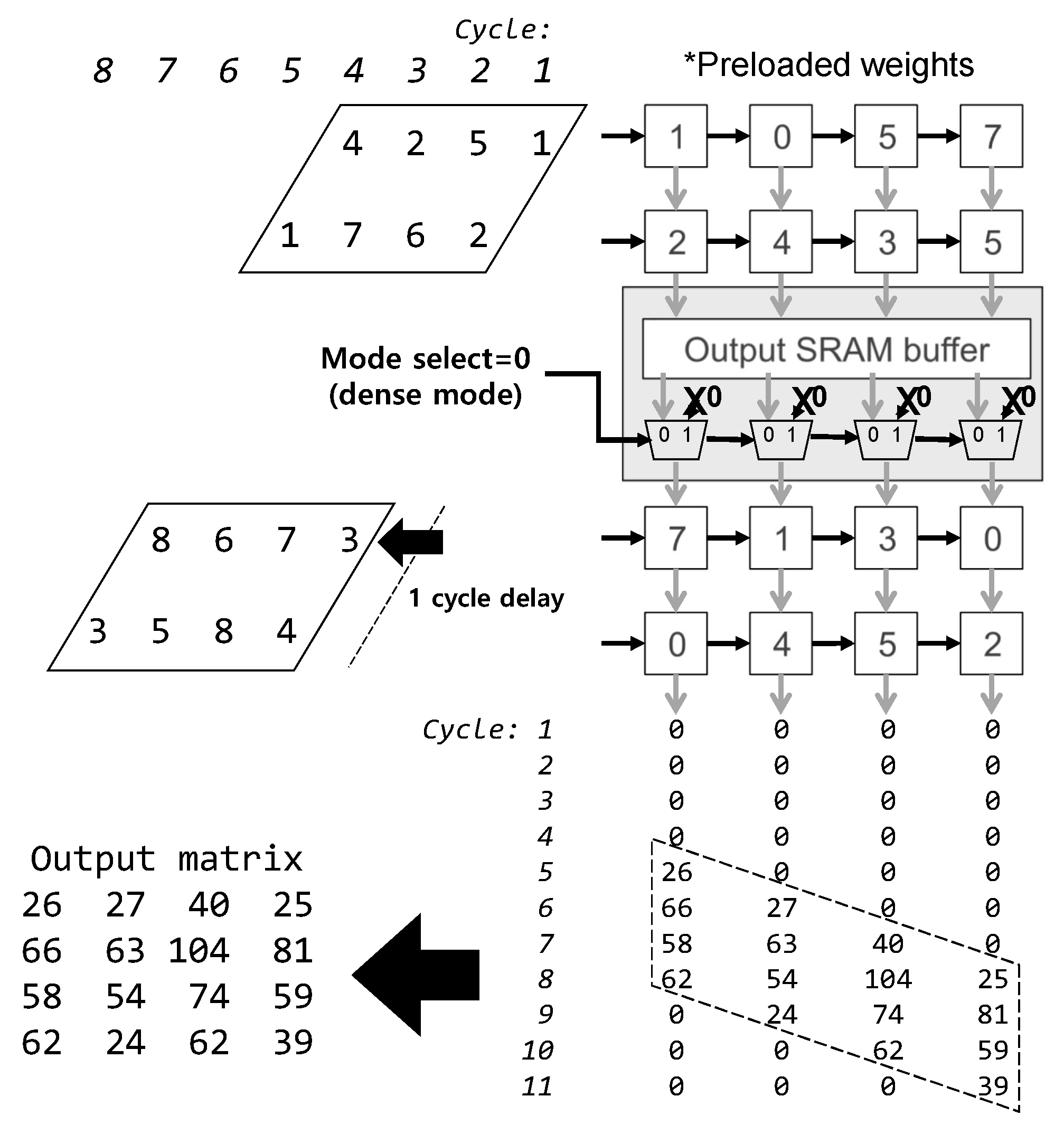
4.3.2. Dense Mode Operations

In the case of the dense mode operation, our VerSA operates similarly to conventional systolic arrays while the main difference is the consideration of the additional delay from the IPBs. Since the IPB takes one clock cycle, the input streaming should be performed with consideration of the fact that an additional one clock cycle will be taken from the IPB. Thus, for the input streaming to a certain row within a subarray, N clock cycle delays should be added when there are N IPBs above the current row. For example, as shown in Figure 7, the input streaming of the rows in the second subarray is delayed by one clock cycle because there is one IPB above the rows in the second subarray. Though the remaining operations can be performed similarly to the conventional SA, there should be a little performance overhead when compared to the conventional SA due to the additional delay from the IPBs.

4.4. Implementation and Logic Synthesis

We have implemented our VerSA hardware architecture with a Verilog hardware description language (HDL) and synthesized it with 32 nm process technology using Design Compiler. The power, performance, and area (PPA) of the input and output buffers with the SRAM cells are estimated by CACTI7 [18] and incorporated into our PPA evaluation results. For each PE, we use an integer 8-bit MAC unit (multiplier and adder) and registers for preloaded weights and temporarily latched partial sums and inputs. One should note that 8-bit integer formats are widely used in DNN inference engines due to the prevalence of quantization methods [19]. For systolic arrays, we used 128 × 128 and 256 × 256 PE array dimensions, which are widely used in commercial systolic arrays [2]. The number of subarrays ( N u m s u b a r r a y ) in VerSA is set to eight for both dimensions. As summarized in Table 2, both the conventional systolic array and our VerSA were synthesized with a 250 MHz clock frequency. The size of the SRAM buffers for a 128 × 128 (256 × 256) architecture is 64 KB (256 KB) for each input and output buffer. In the case of VerSA, the output buffers are distributed across the IPBs, and the output buffer is also placed below the last subarray. Though there could be various design choices, we evenly distribute the output buffers to the IPBs and the last output buffer, thereby resulting in 8 KB (32 KB) for each IPB and last output buffer in a 128 × 128 (256 × 256) configuration. As shown in Table 2, adding the IPB in VerSA increases the area and power consumption when compared to the conventional SA. As a result, the 128 × 128 (256 × 256) VerSA increases the area and power by 14.8% (12.6%) and 14.4% (11.7%), respectively, when compared to the conventional SA with the same array dimension.

5. Evaluation

5.1. Methodology

For cycle-level performance evaluations, we use SCALE-sim [17], which is an architectural simulator for systolic arrays. For the evaluations of VerSA, we incorporated the cycle-level impact of the IPBs and exact cycle-level behaviors together in the simulator. We used the synthesis results from Table 2 for the clock cycle time and power, which are then used in the performance and energy evaluations. For the benchmarks, we used the following various matrix multiplications from real-world DNN workloads: GPT2 [20], GNMT [21], NCF [22], Transformer [23], ResNet-50 [24], and VGG-19 [25]. For the purpose of comparison with the state-of-the-art MM accelerator, we compared our VerSA with a row-wise sparse matrix multiplication hardware accelerator [12] with SuiteSparse benchmarks [26].

5.2. Performance

Figure 8 summarizes the speedup results of our VerSA in comparison to the conventional SA in both the sparse mode and dense mode across different sparsity levels. For the comparison of our VerSA with the conventional SA, the same clock frequency (250 MHz) was used for both designs. We show the relative performance of VerSA in comparison to the conventional SA with the metric of speedup. The speedup of VerSA against the conventional SA (ConvSA) can be formulated as follows:
Speedup   of   VerSA   against   ConvSA = P e r f V e r S A P e r f C o n v S A = E x e c t i m e C o n v S A E x e c t i m e V e r S A ,
where P e r f X and E x e c t i m e X are the performance of X and the execution time of X, respectively.
In the case of the sparse mode, our 128 × 128 VerSA (256 × 256) leads to better performance when compared to the conventional SA by 1.16×–1.45× (1.21×–1.60×) across various sparsity levels. The early termination that occurs due to the IPBs in our VerSA leads to the clock cycle (i.e., execution time) reduction that is required for the MM workload execution. As the array size increases, the performance gain of the sparse mode is likely to increase because it is likely to skip more rows in the case of bigger arrays; meanwhile, the conventional SA must pass through the whole rows to generate the outputs. In the case of the dense mode, our 128 × 128 (256 × 256) VerSA shows only a little performance overhead by 0.85% (0.52%) when compared to the conventional SA. As our model has a bigger array size with fixed N u m s u b a r r a y , the performance overhead caused by the additional IPBs is reduced.
Table 3 shows the speedup of our VerSA against the state-of-the-art SpMM accelerator [12]. In this paper, we used the same clock frequency for both the SpMM accelerator and VerSA to compare the performance. Please note that this is a very conservative assumption when considering the logic complexity between the two designs; our VerSA has a much lower logic complexity than the SpMM accelerator in [12].
In the case of the large workloads with a relatively high sparsity (web-Google, mario002, amazon0312, and m133-b2), our 128 × 128 (256 × 256) VerSA results in 82.8–98.0% (38.6–92.9%) performance losses, on average, when compared to the accelerator in [12]. Since the SpMM accelerator in [12] primarily focuses on sparse matrix multiplication, it has an advantage when dealing with large and sparse MM workloads. However, for the rest of the workloads, our VerSA shows a speedup of more than three times when compared to the accelerator used in [12]. It means that our VerSA hardware accelerator performs matrix multiplication with a much higher versatility when compared to the SpMM accelerator.

5.3. Energy

Figure 9 depicts the energy results of our VerSA relative to the conventional SA. We present the energy consumption of VerSA relative to that of the conventional SA (ConvSA), which can be formulated as follows:
Energy   consumption   of   VerSA   relative   to   ConvSA = E n e r g y V e r S A E n e r g y C o n v S A ,
where E n e r g y X is the energy consumption in the case of X.
In the case of the sparse mode, our 128 × 128 (256 × 256) VerSA shows lower energy consumption when compared to the conventional SA by 1.6–21.3% (7.5–30.2%) across various sparsity levels. Despite the increased power consumption, thanks to the reduced execution time, the total energy consumption of our VerSA is less than that of the conventional SA. In the case of the dense mode, our 128 × 128 (256 × 256) VerSA consumes more energy, by 15.4% (12.3%), when compared to the conventional SA due to the additional clock cycles and power consumption of the IPBs.

6. Discussion

6.1. Hardware Overhead

As mentioned in Section 4.4, our VerSA hardware architecture shows power and area overheads when compared to the conventional SA. Our VerSA hardware obviously employs IPBs, which correspond to additional logic gates when compared to the conventional SA. However, VerSA has several advantages over the conventional SA or SpMM hardware when implementing a system. When integrating the intellectual properties (IPs) in a single chip or system to execute both dense and sparse MMs, VerSA enables system implementation with a VerSA hardware block only while also not requiring heterogeneous integration (i.e., integrating different hardware blocks for dense MM and sparse MM). It also implies that integration with VerSA leads to less hardware complexity and better IP reusability, which eventually results in a cost reduction. Moreover, by enabling both dense and sparse MMs within a single hardware, the VerSA-integrated system will have better hardware utilization when compared to the system with heterogeneous integration. In the case of a system with heterogeneous integration, when performing dense MM, the sparse MM hardware block will be in the idle state, and also vice versa.

6.2. Software Overhead

VerSA requires several software supports such as weight matrix condensing and column restoration. Weight matrix condensing requires the search of zero values in the weight matrix, and it condenses the matrix in a column-wise manner. Performing the matrix condensing can incur non-negligible execution time overhead. However, once the weight matrix is preloaded into VerSA, the weights can be reused across a large number of DNN inferences because the weights are not changed during the DNN inference. This means that the weight matrix condensing overhead can be amortized across multiple DNN inferences, thus resulting in negligible execution time overhead. Though the column restoration delay overhead seems to be inevitable, the relative delay overhead of the column restoration would also be negligible when compared to that of the partial sum matrix accumulation for the blocked MM. As modern DNN workloads need to execute the multiplication between operand matrices with a very large dimension (where a single MM should be executed by multiple MM operations with the blocked operand matrices and accumulation among the partial sum matrices), the blocked MM will be frequently executed for DNN inferences. This means the delay overhead from the column restoration would be negligible when running real-world DNN workloads.

6.3. Limitations of This Work

The limitations of this work can be summarized as follows:
  • In the evaluation results, we only considered the hardware execution time. Though the software execution time overhead could be marginal, as mentioned in Section 6.2, it would also be desirable for evaluating end-to-end performance;
  • Since the main contribution of this paper is to design VerSA architecture, our evaluation is based on cycle-level simulation and logic synthesis results. A verification and evaluation with full system implementation and software supports (e.g., an implementation in field programmable gate arrays) would also be interesting;
  • As presented in Section 5.2 and Section 5.3, our hardware architecture has inevitable performance and energy overheads when performing dense MM when compared to the conventional SA. This is an inherent limitation that arises from the VerSA architecture design. However, considering that the contemporary DNN models have non-negligible sparsity, our VerSA can sufficiently compensate for the performance and energy overheads of the dense MM.
Overcoming the limitations listed above can be an interesting future research direction, and we have a plan to further delve into these topics as our future work.

7. Conclusions

Though conventional systolic arrays have been widely used to accelerate matrix multiplication, they are not efficient for sparse matrix multiplication (SpMM) due to their inability to skip the ineffectual operations. To resolve this problem, many hardware accelerators have been proposed, which show much better performance when compared to the conventional systolic array when running sparse matrix multiplication workloads. However, most SpMM hardware architectures are not suitable for dense matrix multiplication. In this paper, we propose VerSA architecture, a versatile systolic array architecture to accelerate both dense and sparse matrix multiplications. By adding intermediate paths and SRAM buffers (IPB), SpMM can be terminated earlier than the conventional SA, thus accelerating SpMM. Since our architecture is built upon a systolic array, dense MM can also be executed with negligible performance overhead. In comparison to the conventional SA, our 256 × 256 VerSA architecture improves the performance of SpMM by 1.21×–1.60× across various sparsity levels while there is only a 0.52% performance overhead in the case of dense MM. In terms of energy consumption, our 256 × 256 VerSA architecture reduces the energy consumption of SpMM by 7.5–30.2%, while there is only a 12.3% energy overhead in the case of dense MM. DNN hardware accelerators are widely deployed in mobile edge or embedded devices. In addition, DNN workloads are also becoming increasingly diverse, thus necessitating the acceleration of both dense and sparse matrix multiplications. We believe that our VerSA can be a promising alternative that can be employed for both dense and sparse matrix multiplications with a unified hardware architecture.

Author Contributions

Conceptualization, J.S. and J.K.; Methodology, J.S. and J.K.; Software, J.S.; Validation, J.S. and J.K.; Investigation, J.S.; Data curation, J.S.; Writing—original draft, J.S. and J.K.; Writing—review & editing, J.S. and J.K.; Visualization, J.S.; Supervision, J.K.; Project administration, J.K.; Funding acquisition, J.K. All authors have read and agreed to the published version of the manuscript.

Funding

This research was supported by the Basic Science Research Program through the National Research Foundation of Korea (NRF), which was funded by the Ministry of Education (NRF-2021R1I1A3A04037455) and Samsung Electronics Co., Ltd. (IO221005-02702-01). The EDA tool was supported by the IC Design Education Center (IDEC).

Data Availability Statement

Data are contained within the article.

Conflicts of Interest

The authors declare no conflict of interest.

References

  1. Jouppi, N.P.; Young, C.; Patil, N.; Patterson, D.; Agrawal, G.; Bajwa, R.; Bates, S.; Bhatia, S.; Boden, N.; Borchers, A.; et al. In-Datacenter Performance Analysis of a Tensor Processing Unit. In Proceedings of the 44th Annual International Symposium on Computer Architecture, Toronto, ON, Canada, 24–28 June 2017; pp. 1–12. [Google Scholar] [CrossRef]
  2. Jouppi, N.P.; Hyun Yoon, D.; Ashcraft, M.; Gottscho, M.; Jablin, T.B.; Kurian, G.; Laudon, J.; Li, S.; Ma, P.; Ma, X.; et al. Ten Lessons From Three Generations Shaped Google’s TPUv4i: Industrial Product. In Proceedings of the 2021 ACM/IEEE 48th Annual International Symposium on Computer Architecture (ISCA), Valencia, Spain, 14–18 June 2021; pp. 1–14. [Google Scholar] [CrossRef]
  3. Jouppi, N.; Kurian, G.; Li, S.; Ma, P.; Nagarajan, R.; Nai, L.; Patil, N.; Subramanian, S.; Swing, A.; Towles, B.; et al. TPU v4: An Optically Reconfigurable Supercomputer for Machine Learning with Hardware Support for Embeddings. In Proceedings of the 50th Annual International Symposium on Computer Architecture, Orlando, FL, USA, 17–21 June 2023. [Google Scholar] [CrossRef]
  4. Pal, S.; Beaumont, J.; Park, D.H.; Amarnath, A.; Feng, S.; Chakrabarti, C.; Kim, H.S.; Blaauw, D.; Mudge, T.; Dreslinski, R. OuterSPACE: An Outer Product Based Sparse Matrix Multiplication Accelerator. In Proceedings of the 2018 IEEE International Symposium on High Performance Computer Architecture (HPCA), Vienna, Austria, 24–28 February 2018; pp. 724–736. [Google Scholar] [CrossRef]
  5. Gondimalla, A.; Chesnut, N.; Thottethodi, M.; Vijaykumar, T.N. SparTen: A Sparse Tensor Accelerator for Convolutional Neural Networks. In Proceedings of the 52nd Annual IEEE/ACM International Symposium on Microarchitecture, Columbus, OH, USA, 12–16 October 2019; pp. 151–165. [Google Scholar] [CrossRef]
  6. Qin, E.; Samajdar, A.; Kwon, H.; Nadella, V.; Srinivasan, S.; Das, D.; Kaul, B.; Krishna, T. SIGMA: A Sparse and Irregular GEMM Accelerator with Flexible Interconnects for DNN Training. In Proceedings of the 2020 IEEE International Symposium on High Performance Computer Architecture (HPCA), San Diego, CA, USA, 22–26 February 2020; pp. 58–70. [Google Scholar] [CrossRef]
  7. Zhang, Z.; Wang, H.; Han, S.; Dally, W.J. SpArch: Efficient Architecture for Sparse Matrix Multiplication. In Proceedings of the 2020 IEEE International Symposium on High Performance Computer Architecture (HPCA), San Diego, CA, USA, 22–26 February 2020; pp. 261–274. [Google Scholar] [CrossRef]
  8. Hojabr, R.; Sedaghati, A.; Sharifian, A.; Khonsari, A.; Shriraman, A. SPAGHETTI: Streaming Accelerators for Highly Sparse GEMM on FPGAs. In Proceedings of the 2021 IEEE International Symposium on High-Performance Computer Architecture (HPCA), Seoul, Republic of Korea, 27 February–3 March 2021; pp. 84–96. [Google Scholar] [CrossRef]
  9. Srivastava, N.; Jin, H.; Liu, J.; Albonesi, D.; Zhang, Z. MatRaptor: A Sparse-Sparse Matrix Multiplication Accelerator Based on Row-Wise Product. In Proceedings of the 2020 53rd Annual IEEE/ACM International Symposium on Microarchitecture (MICRO), Athens, Greece, 17–21 October 2020; pp. 766–780. [Google Scholar] [CrossRef]
  10. Zhang, G.; Attaluri, N.; Emer, J.S.; Sanchez, D. Gamma: Leveraging Gustavson’s Algorithm to Accelerate Sparse Matrix Multiplication. In Proceedings of the 26th ACM International Conference on Architectural Support for Programming Languages and Operating Systems, Virtual, 19–23 April 2021; pp. 687–701. [Google Scholar] [CrossRef]
  11. Kwon, J.; Kong, J.; Munir, A. Sparse convolutional neural network acceleration with lossless input feature map compression for resource-constrained systems. IET Comput. Digit. Technol. 2022, 16, 29–43. [Google Scholar] [CrossRef]
  12. Lee, J.H.; Park, B.; Kong, J.; Munir, A. Row-Wise Product-Based Sparse Matrix Multiplication Hardware Accelerator With Optimal Load Balancing. IEEE Access 2022, 10, 64547–64559. [Google Scholar] [CrossRef]
  13. Li, S.; Huai, S.; Liu, W. An Efficient Gustavson-Based Sparse Matrix–Matrix Multiplication Accelerator on Embedded FPGAs. IEEE Trans. Comput.-Aided Des. Integr. Circuits Syst. 2023, 42, 4671–4680. [Google Scholar] [CrossRef]
  14. Li, Z.; Li, J.; Chen, T.; Niu, D.; Zheng, H.; Xie, Y.; Gao, M. Spada: Accelerating Sparse Matrix Multiplication with Adaptive Dataflow. In Proceedings of the 28th ACM International Conference on Architectural Support for Programming Languages and Operating Systems, Vancouver, BC, Canada, 25–29 March 2023; pp. 747–761. [Google Scholar] [CrossRef]
  15. Muñoz Martínez, F.; Garg, R.; Pellauer, M.; Abellán, J.L.; Acacio, M.E.; Krishna, T. Flexagon: A Multi-dataflow Sparse-Sparse Matrix Multiplication Accelerator for Efficient DNN Processing. In Proceedings of the 28th ACM International Conference on Architectural Support for Programming Languages and Operating Systems, Vancouver, BC, Canada, 25–29 March 2023; pp. 252–265. [Google Scholar] [CrossRef]
  16. Sze, V.; Chen, Y.H.; Yang, T.J.; Emer, J.S. Efficient Processing of Deep Neural Networks: A Tutorial and Survey. Proc. IEEE 2017, 105, 2295–2329. [Google Scholar] [CrossRef]
  17. Samajdar, A.; Joseph, J.M.; Zhu, Y.; Whatmough, P.; Mattina, M.; Krishna, T. A systematic methodology for characterizing scalability of DNN accelerators using SCALE-sim. In Proceedings of the 2020 IEEE International Symposium on Performance Analysis of Systems and Software (ISPASS), Boston, MA, USA, 23–25 August 2020; pp. 58–68. [Google Scholar] [CrossRef]
  18. Balasubramonian, R.; Kahng, A.B.; Muralimanohar, N.; Shafiee, A.; Srinivas, V. CACTI 7: New Tools for Interconnect Exploration in Innovative Off-Chip Memories. ACM Trans. Archit. Code Optim. 2017, 14, 1–25. [Google Scholar] [CrossRef]
  19. Han, S.; Mao, H.; Dally, W.J. Deep Compression: Compressing Deep Neural Network with Pruning, Trained Quantization and Huffman Coding. In Proceedings of the 4th International Conference on Learning Representations (ICLR), San Juan, Puerto Rico, 2–4 May 2016. [Google Scholar]
  20. Radford, A.; Wu, J.; Child, R.; Luan, D.; Amodei, D.; Sutskever, I. Language Models are Unsupervised Multitask Learners. OpenAI 2019, 1, 9. [Google Scholar]
  21. Wu, Y.; Schuster, M.; Chen, Z.; Le, Q.V.; Norouzi, M.; Macherey, W.; Krikun, M.; Cao, Y.; Gao, Q.; Macherey, K.; et al. Google’s Neural Machine Translation System: Bridging the Gap between Human and Machine Translation. arXiv 2016, arXiv:1609.08144. [Google Scholar] [CrossRef]
  22. He, X.; Liao, L.; Zhang, H.; Nie, L.; Hu, X.; Chua, T.S. Neural Collaborative Filtering. In Proceedings of the 26th International Conference on World Wide Web, Perth, Australia, 3–7 April 2017; pp. 173–182. [Google Scholar] [CrossRef]
  23. Vaswani, A.; Shazeer, N.; Parmar, N.; Uszkoreit, J.; Jones, L.; Gomez, A.N.; Kaiser, L.u.; Polosukhin, I. Attention is All you Need. arXiv 2017, arXiv:1706.03762. [Google Scholar] [CrossRef]
  24. He, K.; Zhang, X.; Ren, S.; Sun, J. Deep Residual Learning for Image Recognition. In Proceedings of the 2016 IEEE Conference on Computer Vision and Pattern Recognition (CVPR), Las Vegas, NV, USA, 27–30 June 2016; pp. 770–778. [Google Scholar] [CrossRef]
  25. Simonyan, K.; Zisserman, A. Very Deep Convolutional Networks for Large-Scale Image Recognition. In Proceedings of the 3rd International Conference on Learning Representations (ICLR), San Diego, CA, USA, 7–9 May 2015. [Google Scholar]
  26. Davis, T.A.; Hu, Y. The university of Florida sparse matrix collection. ACM Trans. Math. Softw. 2011, 38, 1–25. [Google Scholar] [CrossRef]
Figure 1. The conventional systolic array architecture with weight stationary dataflow. When performing A × B = C , A, B, and C correspond to the input (A in the figure), weight (W in the figure), and output (O in the figure), respectively.
Electronics 13 01500 g001
Figure 2. The overall execution flow of the VerSA architecture (A × B = C). The steps from ➀ to ➆ correspond to sparse mode operations while those from ⓐ to ⓕ correspond to dense mode operations.
Electronics 13 01500 g002
Figure 3. An example of a column-wise matrix condensing with a 4 × 8 weight matrix and N u m R o w s s u b a r r a y = 2. The gray and white cells represent the non-zero and zero weight elements, respectively.
Electronics 13 01500 g003
Figure 4. The hardware architecture of VerSA. The internal architecture of a single processing element in VerSA is the same as that in the conventional SA. In the case of the dense mode, the hardware performs the operations of Steps ⓑ, ⓓ, and ⓔ, as shown in Figure 2. In the case of the sparse mode, the hardware performs the operations of Steps ➁, ➃, and ➄, as shown in Figure 2.
Electronics 13 01500 g004
Figure 5. An example of sparse mode operations in VerSA.
Electronics 13 01500 g005
Figure 6. The restoration of the partial sum matrices and summation in VerSA, which correspond to the operations of Steps ➅ and ➆ in Figure 2.
Electronics 13 01500 g006
Figure 7. An example of dense mode operations in VerSA.
Electronics 13 01500 g007
Figure 8. The speedup of VerSA architecture when compared to the conventional SA. SM_X% represents the sparse mode with an X% sparsity level. DM is the dense mode. The N u m s u b a r r a y is set to eight in both 128 × 128 and 256 × 256 SA.
Electronics 13 01500 g008
Figure 9. The energy consumption of our VerSA normalized to the conventional SA (=1.0). SM_X% is the sparse mode with an X% sparsity level. DM means the dense mode.
Electronics 13 01500 g009
Table 1. Summarization the design parameter notation in VerSA.
DescriptionNotation Used in the Paper
Total number of rows in the SA N u m R o w s t o t a l
The number of rows in a single subarray N u m R o w s s u b a r r a y
The number of subarrays in the SA N u m s u b a r r a y
The number of IPBs N u m I P B = N u m s u b a r r a y − 1
Table 2. A logic synthesis comparison of the conventional SA (Conv_SA) and VerSA.
Array Size Num subarray Clock FrequencyDesign Area (mm2)Power (W)
Conv_SA128 × 128N/A250 MHz19.23461.4145
VerSA822.09971.6184
Conv_SA256 × 256N/A76.90425.6125
VerSA886.60916.2699
Table 3. Speedup of our VerSA against the state-of-the-art sparse MM accelerator with a 4PE configuration [12].
MatrixDimensionSparsity128 × 128 Speedup256 × 256 Speedup
web-Google916 k × 916 k99.9994%0.0200.071
mario002390 k × 390 k99.9986%0.1260.449
amazon0312401 k × 401 k99.9981%0.1720.614
m133-b2200 k × 200 k99.9980%0.1540.552
cage12130 k × 130 k99.9883%3.48612.446
2cubes-sphere101 k × 101 k99.9843%5.85820.908
filter3D106 k × 106 k99.9766%9.93535.460
ca-CondMat23 k × 23 k99.9656%23.55383.665
wikiVote8.3 k × 8.3 k99.8529%206.464694.082
poisson3Da14 k × 14 k99.8179%284.4151,005.949
Facebook4 k × 4 k98.9331%10,692.45836,502.207
Disclaimer/Publisher’s Note: The statements, opinions and data contained in all publications are solely those of the individual author(s) and contributor(s) and not of MDPI and/or the editor(s). MDPI and/or the editor(s) disclaim responsibility for any injury to people or property resulting from any ideas, methods, instructions or products referred to in the content.

