Article

Instantaneous Kinematics and Free-from-Singularity Workspace of 3-XXRRU Parallel Manipulators

by
Henrique Simas
1,
Raffaele Di Gregorio
2,* and
Roberto Simoni
3
1
Raul Guenther Laboratory of Applied Robotics, Department of Mechanical Engineering, Federal University of Santa Catarina, Florianópolis 88040-900, SC, Brazil
2
Laboratory of Mechatronics and Virtual Prototyping (LaMaViP), Department of Engineering, University of Ferrara, Via Saragat, 1, 44100 Ferrara, Italy
3
Department of Mobility Engineering, Federal University of Santa Catarina, Joinville 89219-600, SC, Brazil
*
Author to whom correspondence should be addressed.
Robotics 2023, 12(5), 138; https://doi.org/10.3390/robotics12050138
Submission received: 30 June 2023 / Revised: 27 September 2023 / Accepted: 3 October 2023 / Published: 5 October 2023
(This article belongs to the Special Issue Kinematics and Robot Design VI, KaRD2023)

Abstract

:
3-XXRRU parallel manipulators (PMs) constitute a family of six-degrees-of-freedom (DOF) PMs with three limbs of type XXRRU, where R and U stand for revolute pair and universal joint, respectively, and XX indicates any actuated two-DOF mechanism that moves the axis of the first R-pair. The members of this family share the fact that they all become particular 3-RRU structures when the actuators are locked. By exploiting this feature, the present paper proposes a general approach, which holds for all the members of this family, to analyze the instantaneous kinematics, workspace, and kinetostatic performances of any 3-XXRRU PM. The results of this study include the identification of singularity conditions without reference to a specific actuation system, the proposal of two specific dimensionless performance indices ranging from 0 to 1, the determination of the optimal actuation system, and the demonstration that 3-XXRRU PMs, when appropriately sized and actuated, possess a broad singularity-free workspace that is also fully isotropic. These findings hold significance in the context of the dimensional synthesis and control of 3-XXRRU PMs. Moreover, when combined with the closed-form solutions for their positional analysis, as demonstrated in a previous publication by the same authors, 3-XXRRU PMs emerge as intriguing alternatives to other six-DOF PMs. The efficacy of the proposed approach is further illustrated through a case study.

1. Introduction

Parallel manipulators (PMs) [1] feature an end effector (platform) connected to a frame (base) by means of a number of kinematic chains (limbs) that can be of any type (i.e., either open or closed or even hybrid chains). The multiple connections between the platform and base make PMs stiffer and more precise than their serial counterparts but, at the same time, make their kinematics more complex and their workspace smaller.
Usually, the number of limbs is equal to the degrees of freedom (DOF) of the PM, and the limbs are open chains with one actuator per limb, which is located on or near the base to reduce the mobile masses [1,2,3,4]. The higher the limb number, the smaller the workspace since the number of possible limb collisions increases. Thus, reducing the limb number without changing the DOF number and actuators’ locations is of interest. Such a goal is reachable by using hybrid chains as limbs where more than one actuator per limb, located on the base, controls as many joint variables through a suitable closed-chain transmission. In the literature, a number of six-DOF PMs with only three limbs and more than one actuator per limb have been proposed (see [5,6,7,8,9,10,11,12,13,14], for instance).
In this context, the authors of the present paper together with Meneghini [15] have proposed a family of six-DOF PMs with three limbs of XXRRU type1, where R and U stand for revolute pair and universal joint, respectively, and XX indicates any actuated two-DOF mechanism that moves the axis of the first R-pair. In addition, they have shown that both the direct and the inverse position analyses of 3-XXRRU PMs are solvable in closed form.
The presence of singularities [16,17,18,19,20,21,22] can further reduce PMs’ useful workspace. By considering the relationship between actuated-joint rates (inputs) and platform twist (output) as an input–output relationship (hereafter named IOR) [16,17,18,19,20], singularities are mechanism configurations where the one-to-one correspondence, which the IOR2 states, between actuated-joint rates and platform twist fails. With reference to the IOR, two instantaneous kinematics problems are definable: the instantaneous inverse kinematics (IIK) problem, which is the determination of one set of actuated-joint rates compatible with one assigned platform twist, and the instantaneous forward kinematics (IFK) problem, which is the determination of one platform twist compatible with one assigned set of actuated-joint rates. Accordingly, three main types of singularities are identifiable [16]: (I) serial singularities, which are mechanism configurations where the IIK is unsolvable, (II) parallel singularities, which are mechanism configurations where the IFK is unsolvable, and (III) the mechanism configurations where both the problems are unsolvable.
Serial singularities are by definition configurations from which the platform cannot exit by moving along any direction (twist), that is, there is a local reduction in the platform’s DOF number. Such a condition occurs at the workspace boundaries. Differently, parallel singularities are by definition configurations where the actuated joints are not enough to fully control the platform twist, that is, somehow, there is a local increase in the platform’s DOF number. This condition can occur only in PMs and, unfortunately, it usually occurs inside the workspace. The duality, the virtual work principle states between instantaneous kinematics and statics, brings one to conclude that, at a parallel singularity, a small load (even elementary) applied to the platform needs infinite generalized torques at least in one actuator to be equilibrated. Moreover, the nearer the PM configuration to a parallel singularity, the higher the internal loads in the links and the generalized torques in the actuators. In short, a PM must stay far enough from parallel singularities to avoid its breakdown. That is the reason why parallel singularities must be identified during PMs’ design and must be avoided during functioning. Therefore, the existence of parallel singularities constitutes a further limitation to the useful workspace of a PM, which might be even tighter than the one due to there being a high number of limbs.
The 3-XXRRU PMs, as proposed in [15], all share a common characteristic: when the actuators are locked, they all transform into specific 3-RRU structures (refer to Figure 1). In each RRU limb of these structures, the axes of the first three R-pairs are parallel, while the axis of the fourth R-pair (i.e., the one fixed to the platform) is perpendicular to the axes of all the other R-pairs3. Leveraging this characteristic, this paper presents a general approach applicable to all such PMs. This approach is used to analyze the instantaneous kinematics, workspace, and kinetostatic performance of any 3-XXRRU PM.
The key findings of this study are as follows:
(i)
Identification of singularity conditions without the need to reference a specific actuation system;
(ii)
Introduction of two dimensionless performance indices ranging from 0 to 1;
(iii)
Determination of the optimal actuation system;
(iv)
Demonstration that suitably sized and actuated 3-XXRRU PMs offer a broad, singularity-free workspace that is fully isotropic.
These results hold significant relevance for the dimensional synthesis and control of 3-XXRRU PMs. Moreover, the availability of closed-form solutions for their position analysis problems positions 3-XXRRU PMs as intriguing alternatives to other six-DOF PMs. The effectiveness of the proposed approach is further illustrated through a case study.
The paper is organized as follows. Section 2 provides the necessary background materials on 3-XXRRU PMs, deduces their IOR for a general geometry, and presents their singularity analysis together with how to evaluate their kinetostatic performances. Then, Section 3 applies the found singularity conditions and performance indices to a case study, and Section 4 discusses the results. Finally, Section 5 draws the conclusions.

2. Materials and Methods

By considering each limb of a PM as a unique articulated joint whose DOF number is equal to the limb connectivity4 [21,22,23], the general mobility criterion5 [21,22] brings one to conclude that adding any number of limbs with connectivity equal to six does not reduce the mobility of the platform with respect to the base (i.e., the resulting PM architecture always has six DOFs). Limbs of XXRRU type have connectivity equal to six when the two DOFs provided by the XX mechanism do not replicate any DOF provided by the remaining RRU kinematic chain. In particular, the first three R-pairs of the RRU chain (Figure 1b), which have parallel axes, generate a planar motion with a motion plane perpendicular to the axes of these R-pairs. Then, the fourth R-pair of the RRU chain (i.e., the one adjacent to the platform) adds a rotation around an axis that is parallel to the above-said motion plane. Therefore, in order to make the platform motion a general six-DOF motion through an XXRRU limb, the further two DOFs of the XX mechanism must provide either a general reorientation of the above-said motion plane (i.e., a general change in the direction of the axes of the first three R-pairs) or a translation perpendicular to the above-mentioned motion plane together with a particular reorientation of the same plane that involves only one DOF. If these conditions are respected in all three XXRRU limbs, the resulting 3-XXRRU PM will have six DOFs.
When the actuators are locked, all of the 3-XXRRU PMs, presented in [15], become 3-RRU structures (Figure 1). In the i-th RRU limb (Figure 1b), for i = 1, 2, 3, the axis, (Ai, ni)6, of the first R-pair is located through the coordinates of a point, Ai, belonging to it, and a unit vector, ni, parallel to it. The axis, (Ci, mi), of the fourth R-pair, fixed to the platform, is located through the coordinates of the center, Ci, of the U joint and a unit vector, mi, parallel to it. Without losing generality, point Ai is chosen lying on the plane perpendicular to ni that passes through Ci.
With these notations, the actuated two-DOF mechanism, XX, of the i-th limb may change only two parameters chosen among the Ai coordinates and/or the ni components by respecting the above-defined mobility conditions. Moreover, parallel singularities of 3-XXRRU PMs correspond to configurations of the 3-RRU sub-structure at which the platform can perform elementary motions.

2.1. Input–Output Instantaneous Relationship

The IOR of any 3-XXRRU PM of this family is deducible by time differentiating its constraint equation system, which is writable as follows (see Figure 1b; hereafter, a bold letter denotes a vector and a bold capital letter referable to a point denotes the position vector of that point measured in a reference system fixed to the base):
( C i A i ) n i = 0 i = 1 , 2 , 3
m i n i = 0 i = 1 , 2 , 3
The time derivative of system (1) is:
C ˙ i n i = A ˙ i n i + ( A i C i ) n ˙ i i = 1 , 2 , 3
m ˙ i n i = m i n ˙ i i = 1 , 2 , 3
Let P and ω be a point fixed to the platform and the angular velocity of the platform, respectively. Since points Ci and unit vectors mi, for i = 1, 2, 3, are fixed to the platform, the following relationships of rigid-body mechanics hold [23]:
C ˙ i = P ˙ + ω × ( C i P )         i = 1 , 2 , 3
m ˙ i = ω × m i         i = 1 , 2 , 3
whose introduction into Equations (2a) and (2b), after some simple rearrangements that use the properties of the mixed product of three vectors, yields:
n i P ˙ + [ ( C i P ) × n i ] ω = n i A ˙ i + ( A i C i ) n ˙ i         i = 1 , 2 , 3
( n i × m i ) ω = m i n ˙ i         i = 1 , 2 , 3
Equations (4a) and (4b) are writable in matrix form as follows:
[ N T H T 0 3 × 3 M T ] ( P ˙ ω ) = ( n 1 A ˙ 1 + ( A 1 C 1 ) n ˙ 1 n 2 A ˙ 2 + ( A 2 C 2 ) n ˙ 2 n 3 A ˙ 3 + ( A 3 C 3 ) n ˙ 3 m 1 n ˙ 1 m 2 n ˙ 2 m 3 n ˙ 3 )
where 0 3 × 3 is the 3 × 3 null matrix and $ ^ = ( P ˙ ω ) is the platform twist; whereas N, M, and H are 3 × 3 matrices defined as follows:
N = [ n 1 n 2 n 3 ] ,   M = [ ( n 1 × m 1 ) ( n 2 × m 2 ) ( n 3 × m 3 ) ] ,
H = [ ( C 1 P ) × n 1 ( C 2 P ) × n 2 ( C 3 P ) × n 3 ] ;
In system (5), A ˙ i and n ˙ i , for i = 1, 2, 3, are linearly related to the actuated-joint rates through linear and homogeneous expressions that depend on the type of two-DOF mechanism XX, which is present in the XXRRU limb. System (5) is the IOR of a generic 3-XXRRU PM.

2.2. Singularity Analysis

The singularity analysis, which is the determination of the geometric/analytic conditions that identify the singular configurations (singularities), practically consists of analyzing the IOR of the PM, that is, system (5) for a 3-XXRRU PM.
Regarding the possible actuation choices for these PMs, system (5) immediately reveals that, if the XX mechanisms only move points Ai, for i = 1, 2, 3, (i.e., n ˙ 1 = n ˙ 2 = n ˙ 3 = 0 ), the last three equations, which simply become MT ω = 0, always provide ω = 0 out of singularities that make det(M) = 0. That is, with this actuation choice, the platform can only translate and the 3-XXRRU becomes a 3-DOF translational PM (TPM). The so-obtained TPM is somehow a more general geometry of the Cartesian TPM proposed by Kim and Tsai in [24,25]. Moreover, since A ˙ i only appears in the dot product n i A ˙ i , the only motion direction of point Ai that causes a platform motion is the one along n i . In particular, since the time derivative of n i n i = 1 yields n i n ˙ i = 0 , choosing A ˙ i = a i n ˙ i where ai is an arbitrary scalar constant would give n i A ˙ i = a i n i n ˙ i = 0 , that is, no effect on the platform motion. In short, the XX mechanism of the i-th XXRRU limb can devote at most one actuator to move point Ai and must move it only along n i , and an actuated prismatic (P) pair with sliding direction parallel to n i that moves point Ai does not affect the platform translation through the term n i A ˙ i when the direction of n i changes and the P pair is locked.
Differently, the same analysis, reveals that if the XX mechanisms only change the directions of unit vectors n i , for i = 1, 2, 3, (i.e., A ˙ 1 = A ˙ 2 = A ˙ 3 = 0 ), the platform can perform a general 6-DOF motion since n ˙ i , for i = 1, 2, 3, appears in all six equations of system (5). In particular, since, in the last three equations of system (5), n ˙ i appears only in the dot product m i n ˙ i , the component of n ˙ i that makes the platform orientation change is only the one along the direction of mi. Moreover, since, in the first three equations of system (5), n ˙ i appears only in the dot product ( A i C i ) n ˙ i , the component of n ˙ i that makes the platform translate is only the one along the direction of ( A i C i ) .
The conclusion is that the most effective actuation system is a two-DOF mechanism that, firstly, controls the n i direction and then, after having obtained the desired platform orientation, locks the n i direction through a system of clutches and brakes, and, eventually, uses one of the two actuators previously used to change the n i direction to make the platform translate toward the desired final pose by moving Ai along the n i direction.
The above discussion of the possible actuation choices makes clear that when one entry of the six-tuple that appears on the right-hand side of system (5) is equal to zero, even though A ˙ i and/or n ˙ i are different from zero, some of the actuated-joint rates are indeterminate for an assigned platform twist, that is, a serial singularity occurs. Therefore, from an analytical point of view, a serial singularity occurs when, provided that A ˙ i and/or n ˙ i are different from zero, at least one of the following six conditions is satisfied:
n i A ˙ i + ( A i C i ) n ˙ i = 0 i = 1 , 2 , 3
m i n ˙ i = 0 i = 1 , 2 , 3
Differently, a parallel singularity occurs when the six-tuple on the right-hand side of system (5) is assigned, but the corresponding platform twist is not computable by solving system (5). This can happen if and only if the determinant of the 6 × 6 matrix (parallel Jacobian) that multiplies the platform twist on the left-hand side of system (5) is equal to zero. Since this parallel Jacobian is an upper triangular block matrix, the following relationship holds [26,27]:
det ( N T H T 0 3 × 3 M T ) = det ( N ) det ( M )
where, by remembering definition (6a), the following geometric/analytic explicit expressions of det ( N ) and det ( M ) can be introduced:
det ( N ) = n 1 ( n 2 × n 3 ) ,   det ( M ) = ( n 1 × m 1 ) [ ( n 2 × m 2 ) × ( n 3 × m 3 ) ] .
Therefore, a parallel singularity occurs if and only if one or the other of the following two conditions is satisfied:
n 1 ( n 2 × n 3 ) = 0 ,
( n 1 × m 1 ) [ ( n 2 × m 2 ) × ( n 3 × m 3 ) ] = 0
Since the left-hand sides of both Equations (10a) and (10b) are mixed products of unit vectors, Equation (10a) (Equation (10b)) is satisfied if and only if the three unit vectors n i , for i = 1, 2, 3, (the three unit vectors n i × m i , for i = 1, 2, 3) are all parallel to a unique plane. From a kinematic point of view, the analysis of system (5) reveals that, when Equation (10a) (Equation (10b)) is satisfied, even though the actuated joints are locked, that is, even though A ˙ i = 0 and n ˙ i = 0 for i = 1, 2, 3, P ˙ (ω) has an indeterminate component along the direction perpendicular to the unique plane the three unit vectors n i , for i = 1, 2, 3, (the three unit vectors n i × m i , for i = 1, 2, 3) are parallel to, that is, the platform can translate along (rotate around a line parallel to) that direction.

2.3. Evaluation of Kinetostatic Performance

From a geometric point of view, the absolute value of the mixed product of three unit vectors, u i , for i = 1, 2, 3, where u i can be either n i or n i × m i , is equal to the volume of the rhombohedron (Figure 2) whose three non-parallel edges are parallel to the three unit vectors u i , for i = 1, 2, 3, and have a length equal to one. Such a volume ranges from 0, when the rhombohedron is flattened, to 1, when the rhombohedron is a cube, and, in this case, can be used as an dimensionless index, say ju (≡ | u 1 ( u 2 × u 3 ) | ), of the distance of a non-singular configuration from a parallel singularity since the greater the volume is, the further away the configuration is from satisfying Equation (10). Such an index can be analytically expressed as a function of two angles, θ1,u and θ2,u (Figure 2), which range from 0° to 90°, as follows:
j u | u 1 ( u 2 × u 3 ) | | λ 1 λ 2 λ 3 | = cos θ 1 , u sin θ 2 , u
where λi, for i = 1, 2, 3, are the three eigenvalues of matrix U = [ u 1 u 2 u 3 ] .
Equations (8), (9) and (11) bring one to build the following index, J, for evaluating the kinetostatic performance of a 3-RRU configuration7:
J | n 1 ( n 2 × n 3 ) | | ( n 1 × m 1 ) [ ( n 2 × m 2 ) × ( n 3 × m 3 ) ] | = j n j n × m = cos θ 1 , n sin θ 2 , n cos θ 1 , n × m sin θ 2 , n × m
From a static point of view (Figure 3), the i-th limb applies to the platform one force, Fini, where Fi is the signed magnitude, parallel to ni and with its line of action passing through Ci, and one moment, Mi(ni × mi), where Mi is the signed magnitude, parallel to (ni × mi). Thus, the equilibrium equations of the platform are (Fe and Me,P are the resultant force and the resultant moment about point P of the external force system applied to the platform):
i = 1 , 3 F i n i + F e = 0
i = 1 , 3 F i [ ( C i P ) × n i ] + i = 1 , 3 M i ( n i × m i ) + M e , P = 0
which, in matrix form, become:
[ N 0 3 × 3 H M ] ( F 1 F 2 F 3 M 1 M 2 M 3 ) = ( F e M e , P )
The first three equations of system (14) show that when jn ( | n 1 ( n 2 × n 3 ) | ) is equal to 1 (i.e., matrix N is isotropic [28]), by changing the direction of Fe, the condition | F i | F e , for i = 1, 2, 3, is always satisfied (i.e., no limb must apply a force with a magnitude greater than the one of Fe). Analogously, when a pure moment Me,P (i.e., Me,P ≠ 0 and Fe = 0) is applied to the platform and jn×m ( | ( n 1 × m 1 ) [ ( n 2 × m 2 ) × ( n 3 × m 3 ) ] | ) is equal to 1 (i.e., matrix M is isotropic [28]), the last three equations of system (14) show that, by changing the direction of Me,P, the condition | M i | M e , P , for i = 1, 2, 3, is always satisfied (i.e., no limb must apply a moment with a magnitude greater than the one of Me,P). Accordingly, hereafter, a 3-RRU configuration with jn = 1 (jn×m = 1) is named isotropic with respect to Fe (Me,P). Of course, the best redistribution of loads among the limbs occurs at configurations that are isotropic with respect to both Fe and Me,P, that is, when J = j n j n × m = 1 , hereafter named fully isotropic.

3. Results

This section proves the effectiveness of the relationships deduced in Section 2 by applying them to the analysis of a 3-XXRRU PM with the geometry shown in Figure 4. In particular, the relationships deduced in Section 2 are used here for the determination of the free-from-singularity workspace of that 3-XXRRU PM and of its kinetostatic performances inside that workspace.
The geometry of the studied 3-XXRRU PM has the peculiarity (see Figure 4) that the axes of the three R-pairs adjacent to the platform share a common intersection, point C3, and are mutually orthogonal. As a consequence, this particular geometry allows the introduction of a Cartesian reference system Opxpypzp (Figure 4), fixed to the platform with origin, Op, coincident with C3 and coordinate axes coincident with the axes of the three R-pairs adjacent to the platform.
With reference to Figure 4 and the general notations of Figure 1, the following further specific notations are introduced. xp, yp, and zp are the unit vectors of the xp, yp, and zp coordinate axes, respectively, of the Opxpypzp reference system and are chosen so that xpm1, ypm2, and zpm3. O0x0y0z0 is a Cartesian reference system fixed to the base. l1 and l2 are the lengths of the segments C3C1 and C3C2. In the i-th limb, for i = 1, 2, 3, point Bi is the intersection of the second R-pair’s axis with the plane perpendicular to ni and passing through Ci; also, di and fi are the lengths of the segments AiBi and BiCi, respectively. Moreover, one assumes that the XX mechanism can, firstly, freely orientate unit vector ni and then make the platform translate toward the desired final pose, which, as explained in Section 2.2, is the best actuation technique for 3-XXRRU PMs.
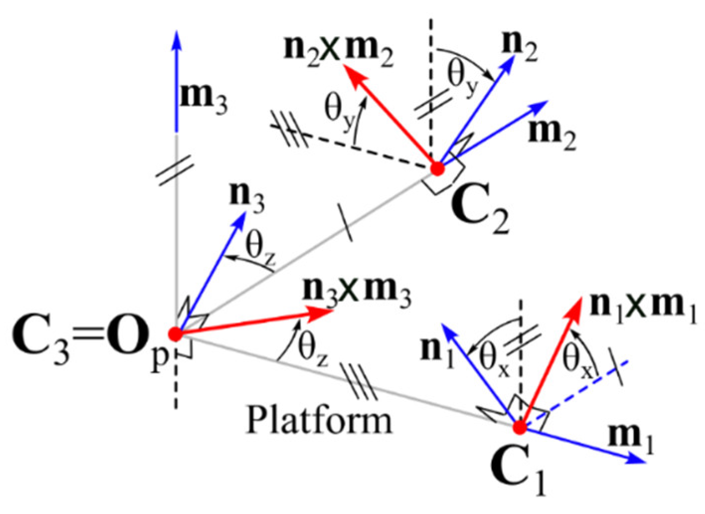
Since the actuation system can freely orientate unit vectors ni, for i = 1, 2, 3, the choice of moving them so that they are always mutually orthogonal is assumed. Such a choice makes all the reached 3-RRU configurations isotropic with respect to Fe (i.e., with jn = 1). Therefore, the kinetostatic performance of each 3-RRU configuration could degrade only because of a jn×m value lower than 1 and can be evaluated by using only the jn×m index. Nevertheless, for this particular geometry and ni motion strategy, the demonstration that follows shows that the index jn×m is equal to one, too (i.e., the platform moves by keeping the 3-XXRRU configuration fully isotropic). Indeed, with reference to Figure 5, the following explicit expressions can be written.
{ n 1 = m 2 sin θ x + m 3 cos θ x n 2 = m 1 sin θ y + m 3 cos θ y n 3 = m 1 sin θ z + m 2 cos θ z
{ n 1 × m 1 = m 3 sin θ x + m 2 cos θ x n 2 × m 2 = m 3 sin θ y m 1 cos θ y n 3 × m 3 = m 2 sin θ z + m 1 cos θ z j n × m = | cos θ x sin θ y cos θ z sin θ x cos θ y sin θ z |
Moreover, since unit vectors ni, for i = 1, 2, 3, are moved by keeping them mutually orthogonal, the following system of three equations in three unknowns must be satisfied:
{ n 1 n 2 = ( m 2 sin θ x + m 3 cos θ x ) ( m 1 sin θ y + m 3 cos θ y ) = cos θ x cos θ y = 0 n 1 n 3 = ( m 2 sin θ x + m 3 cos θ x ) ( m 1 sin θ z + m 2 cos θ z ) = sin θ x cos θ z = 0 n 2 n 3 = ( m 1 sin θ y + m 3 cos θ y ) ( m 1 sin θ z + m 2 cos θ z ) = sin θ y sin θ z = 0
whose solutions are (cosθx, sinθy, cosθz) = (0, 0, 0), which implies (sinθx, cosθy, sinθz) = (±1, ±1, ±1) and (sinθx, cosθy, sinθz) = (0, 0, 0), which implies (cosθx, sinθy, cosθz) = (±1, ±1, ±1). Both these solutions, when introduced into Equation (15b), yield j n × m = 1 , which demonstrates what has been declared above.
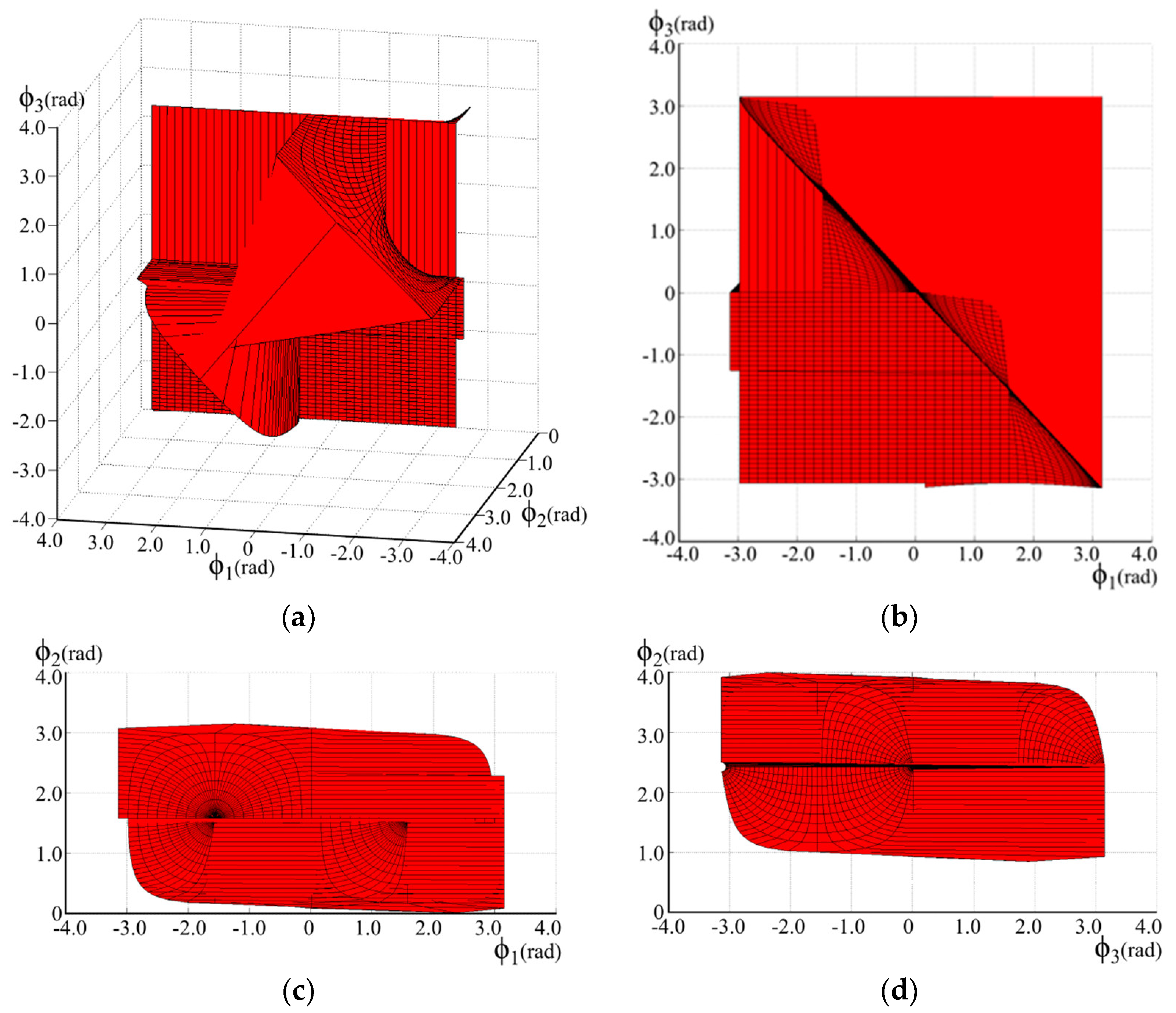
With the above-reported assumptions and choices, the free-from-singularity orientation workspace was numerically determined by using the following data (l.u. stands for arbitrary length unit; the points’ coordinates are measured in O0x0y0z0): A1 = (1, 1, 0)T l.u., A2 = (0, 3, 2)T l.u., A3 = (0, 0, 2)T l.u., l1 = 1.5 l.u., l2 = 2 l.u., d1 = d2 = d3 = 3 l.u., f1 = f2 = f3 = 2.5 l.u. Figure 6 shows the so-determined free-from-singularity orientation workspace (the parameters ϕ1, ϕ2, and ϕ3 on the axes are the ZYZ Euler angles that locate the orientation of Opxpypzp with respect to O0x0y0z0). Figure 7 shows the volume inside which point C3 moves while the directions of unit vectors ni, for i = 1, 2, 3, are modified (by keeping them mutually orthogonal) to make the platform reach the orientation shown in Figure 6 (the coordinates of point C3 measured in O0x0y0z0 are reported on the axes of Figure 7).

4. Discussion

The numerical procedure adopted to determine Figure 6 and Figure 7 firstly considers matrix N as a rotation matrix, since unit vectors ni, for i = 1, 2, 3, must be kept mutually orthogonal, and expresses matrix N through the ZYZ Euler angles (ψ1, ψ2, ψ3) with ψ1, ψ3∈[−π, π] rad and ψ2∈[0, π] rad. Then, it discretizes the values of ψ1, ψ2, and ψ3 by selecting a number, say k, of equally spaced values in their ranges, computes the corresponding k3 platform poses, and keeps only those compatible with the link lengths. Eventually, the k value is increased until the shape of the determined workspace does not change; such a condition was reached for k = 40, and Figure 6 and Figure 7 refer to k = 40. Accordingly, Figure 6 and Figure 7 display the workspace restricted to the fully isotropic configurations, hereafter named the fully isotropic workspace.
The analysis of Figure 6 highlights that the fully isotropic orientation workspace includes an ample portion of the parallelepiped (i.e., ϕ1, ϕ3∈[−π, π] rad and ϕ2∈[0, π] rad) collecting all the possible orientations the platform could assume as a free rigid body. Moreover, the sizes of the excluded regions depend on the chosen link length, which brings one to conclude that, during design, the link lengths can be sized for an assigned fully isotropic orientation workspace.
Accepting non-singular configurations with jnjn,min < 1 and jn×mjn×m,min < 1, where jn,min and jn×m,min are two constant values not equal to zero, is another design choice that could be adopted to obtain the desired free-from-singularity workspace. Such an approach might also be implemented by modifying the control strategy in an already manufactured machine.
Whatever the adopted design criteria happen to be, the above case study proves that, in the family of 3-XXRRU PMs, suitable combinations of geometries and control strategies can be selected which provide good kinetostatic performance in an ample free-from-singularity workspace.
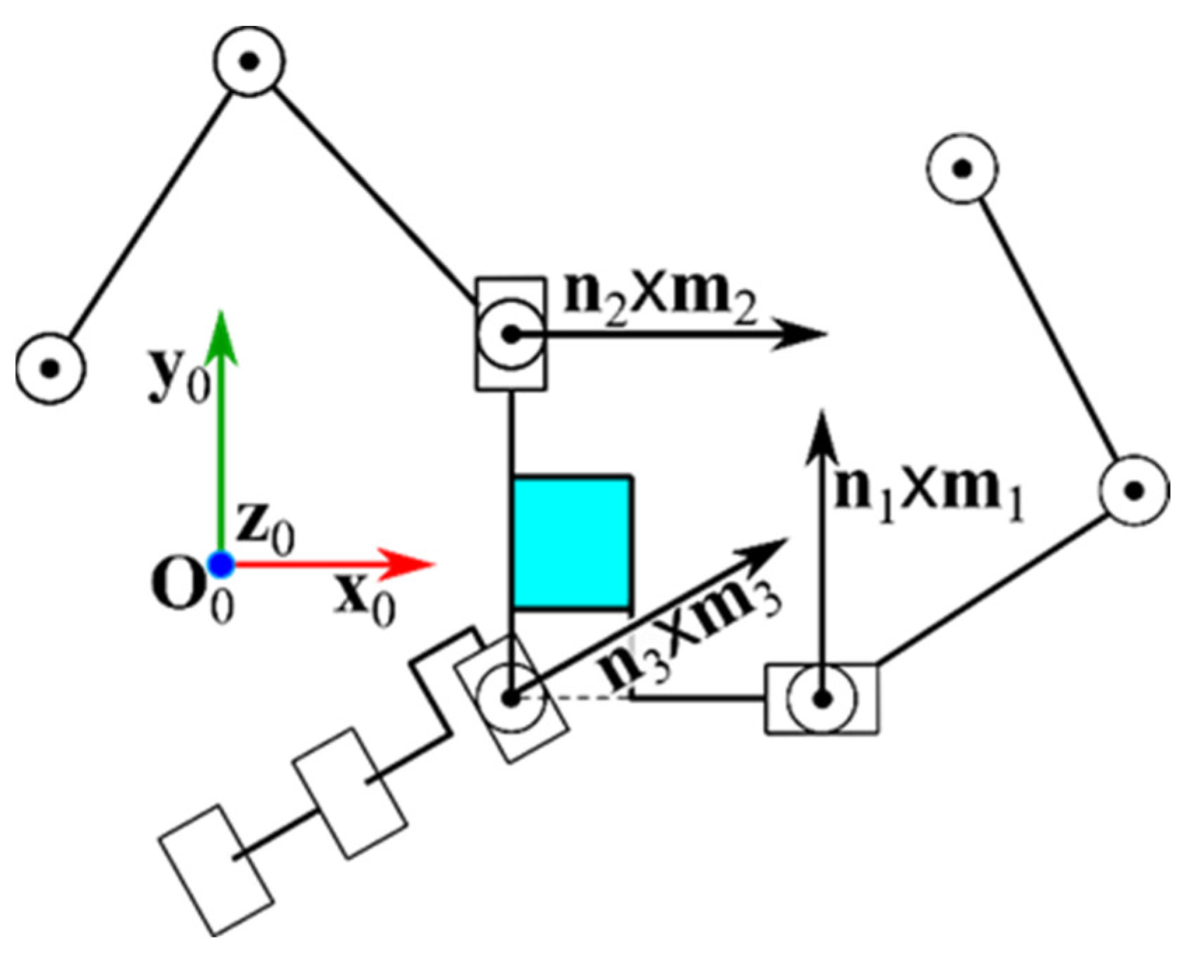
The 3-RRU structure studied in Section 3 lends itself to better illustrate the parallel-singularity conditions (i.e., Equations (10a) and (10b)) through Figure 8 and Figure 9. Figure 8 shows two singular configurations of this structure that satisfy Equation (10a). In particular, the three unit vectors n i , for i = 1, 2, 3, are all parallel to the x0y0-coordinate plane with the three R-pair axes (Ai, ni), for i = 1, 2, 3, that are not coplanar in Figure 8a and are coplanar in Figure 8b. The analysis of Figure 8 clearly shows that the particular disposition of the first three R-pair axes of each limb makes platform translation possible along the z0-coordinate axis. Differently, Figure 9 shows one singular configuration of the same structure that satisfies Equation (10b). Indeed, in such a configuration, the three unit vectors n i × m i , for i = 1, 2, 3, are all parallel to the x0y0-coordinate plane. The analysis of Figure 9 clearly shows that the particular disposition of all the R-pair axes makes the platform rotation possible around the axis (C3, z0).
Eventually, the possible types of XX mechanisms that implement the optimal control strategy identified in Section 2 deserve a more detailed discussion. Firstly, the orientation of ni can be obtained by using any parallel pointing system8 (PPS) among the many proposed in the literature (see, for instance, Refs. [29,30]). Then, by placing a partially actuated cylindrical(C) pair9 on the mobile platform of the PPS, with the translation that is alternatively actuated by one of the two actuators that moves the PPS platform and with the C-pair axis that passes through the center of the spherical motion the PPS imposes to its platform, the desired translation of point Ai along the ni direction can be added to the orientation of ni. The non-actuated rotation of the added C-pair plays the role of the first non-actuated R-pair of the remaining RRU chain of the XXRRU limb. In order to better illustrate this description, Figure 10 shows a possible XXRRU limb where the PPS is a spherical five-bar linkage10. Of course, the system of brakes and clutches that allows the actuation of the translation in the C-pair by means of one of the two actuators used to orientate the PPS platform needs an ad hoc design that depends on the chosen PPS.

5. Conclusions

This study investigates the instantaneous kinematics, workspace, and kinetostatic performance of a novel family of six-DOF three-legged parallel manipulators (PMs) recently introduced by the authors in a previous publication. These PMs all share the common feature that, when their actuators are locked, they transform into 3-RRU structures and are collectively referred to as 3-XXRRU manipulators.
The examination of the instantaneous kinematics of 3-XXRRU PMs led to the derivation of a general expression for their input–output instantaneous relationship (IOR). Subsequently, the analysis of this IOR unveiled that the singularity conditions for these manipulators can be expressed in a straightforward and easily interpretable geometric manner. This insight provides valuable guidance for selecting an effective actuation system.
In combination with the static analysis of 3-XXRRU PMs, these findings led to the proposal of two dimensionless indices, ranging from 0 to 1, which measure the proximity of a non-singular configuration to the nearest parallel singularity. These indices can be employed in the dimensional synthesis of these PMs. Utilizing these indices, a suitable control strategy has been devised to maintain manipulator isotropy, particularly concerning the resultant force of external forces applied to the platform.
Lastly, a specific platform geometry has been introduced, enabling the attainment of an ample fully isotropic workspace.

6. Patents

Simas H., Simoni R., Meneghini L., Di Gregorio R.: Manipulador paralelo 3XXRRU com três pernas e seis graus de liberdade com volume de trabalho ampliado. 2023; Brazil Patent Application No. BR 10 2023 013289 8; Instituto Nacional da Propriedade Industrial -Brazil.

Author Contributions

Conceptualization, H.S., R.D.G. and R.S.; methodology, H.S., R.D.G. and R.S.; software, H.S.; validation, H.S., R.D.G. and R.S.; formal analysis, H.S., R.D.G. and R.S.; investigation, H.S., R.D.G. and R.S.; writing—original draft preparation, H.S., R.D.G. and R.S.; writing—review and editing, R.D.G.; visualization, R.S.; supervision, R.D.G.; project administration, H.S.; funding acquisition, H.S., R.D.G. and R.S. All authors have read and agreed to the published version of the manuscript.

Funding

This research was developed at the Laboratory of Mechatronics and Virtual Prototyping (LaMaViP) of Ferrara Technopole, supported by the UNIFE FIRD2023 fund, in partnership with the Laboratory of Applied Robotics of Federal University of Santa Catarina, supported by CNPq—Conselho Nacional de Desenvolvimento Científico e Tecnológico (National Council for Scientific and Technological Development) Project 307249/2021-2, Brazil.

Institutional Review Board Statement

Not applicable.

Data Availability Statement

This work does not use experimental data. The data necessary to replicate the computations illustrated in the paper are included in the text of the paper.

Conflicts of Interest

The authors declare no conflict of interest.

References

  1. Merlet, J.-P. Parallel Robots; Springer: Berlin/Heidelberg, Germany, 2000; ISBN 978-1-4020-0385-1. [Google Scholar]
  2. Tsai, L.-W. Mechanism Design: Enumeration of Kinematic Structures According to Function; CRC Press: London, UK, 2001; ISBN 978-0-8493-0901-4. [Google Scholar]
  3. Tsai, L.-W. Robot Analysis: The Mechanics of Serial and Parallel Manipulators; John Wiley & Sons: New York, NY, USA, 1999; ISBN 978-0-4713-2593-2. [Google Scholar]
  4. Meng, J.; Liu, G.; Li, Z. A geometric theory for analysis and synthesis of sub-6 DoF parallel manipulators. IEEE Trans. Robot. 2007, 23, 625–649. [Google Scholar] [CrossRef]
  5. Lin, R.; Guo, W.; Gao, F. Type Synthesis of a Family of Novel Four, Five, and Six Degrees-of-Freedom Sea Lion Ball Mechanisms With Three Limbs. ASME J. Mech. Robot. 2016, 8, 021023. [Google Scholar] [CrossRef]
  6. Cleary, K.; Brooks, T. Kinematic analysis of a novel 6-DOF parallel manipulator. In Proceedings of the 1993 IEEE International Conference on Robotics and Automation, Atlanta, GA, USA, 2–6 May 1993; Volume 1, pp. 708–713. [Google Scholar] [CrossRef]
  7. Jin, Y.; Chen, I.-M.; Yang, G. Kinematic design of a family of 6-DOF partially decoupled parallel manipulators. Mech. Mach. Theory 2009, 44, 912–922. [Google Scholar] [CrossRef]
  8. Coppola, G.; Zhang, D.; Liu, K. A 6-DOF reconfigurable hybrid parallel manipulator. Robot. Comput. Integr. Manuf. 2014, 30, 99–106. [Google Scholar] [CrossRef]
  9. Monsarrat, B.; Gosselin, C.M. Workspace analysis and optimal design of a 3-leg 6-DOF parallel platform mechanism. IEEE Trans. Robot. Autom. 2003, 19, 954–966. [Google Scholar] [CrossRef]
  10. Angeles, J.; Yang, G.; Chen, I.-M. Singularity analysis of three-legged, six-dof platform manipulators with URS legs. IEEE/ASME Trans. Mechatron. 2003, 8, 469–475. [Google Scholar] [CrossRef]
  11. Yang, Z.; Zhang, D. Novel Design of a 3-RRUU 6-DOF Parallel Manipulator. IOP Conf. Ser. Mater. Sci. Eng. 2019, 491, 012006. [Google Scholar] [CrossRef]
  12. Fu, J.; Gao, F. Optimal design of a 3-leg 6-DOF parallel manipulator for a specific workspace. Chin. J. Mech. Eng. 2016, 29, 659–668. [Google Scholar] [CrossRef]
  13. Seward, N.; Bonev, I.A. A new 6-DOF parallel robot with simple kinematic model. In Proceedings of the 2014 IEEE International Conference on Robotics and Automation (ICRA), Hong Kong, China, 31 May–7 June 2014; pp. 4061–4066. [Google Scholar] [CrossRef]
  14. Lu, Y.; Wang, P.; Hou, Z.; Hu, B.; Sui, C.; Han, J. Kinetostatic analysis of a novel 6-DoF 3UPS parallel manipulator with multi-fingers. Mech. Mach. Theory 2014, 78, 36–50. [Google Scholar] [CrossRef]
  15. Simas, H.; Meneghini, L.; Di Gregorio, R.; Simoni, R. Position Analysis of a Novel Family of three-legged 6-DOF Parallel Manipulators of type 3-XXRRU. In Advances in Mechanism and Machine Science: Proceedings of the 16th IFToMM World Congress 2023 [WC2023], Tokyo, Japan, 5–10 November 2023; Okada, M., Ed.; Paper No.: 147; Springer: Cham, Switzerland, 2023. [Google Scholar]
  16. Gosselin, C.M.; Angeles, J. Singularity analysis of closed-loop kinematic chains. IEEE Trans. Robot. Automat. 1990, 6, 281–290. [Google Scholar] [CrossRef]
  17. Ma, O.; Angeles, J. Architecture singularities of platform manipulators. In Proceedings of the 1991 IEEE International Conference on Robotics and Automation, Sacramento, CA, USA, 9–11 April 1991; pp. 1542–1547. [Google Scholar]
  18. Zlatanov, D.; Fenton, R.G.; Benhabib, B. A unifying framework for classification and interpretation of mechanism singularities. ASME J. Mech. Des. 1995, 117, 566–572. [Google Scholar] [CrossRef]
  19. Zlatanov, D.; Bonev, I.A.; Gosselin, C.M. Constraint Singularities as C-Space Singularities. In Proceedings of the 8th International Symposium on Advances in Robot Kinematics (ARK 2002), Caldes de Malavella, Spain, 24–28 June 2002. [Google Scholar]
  20. Zlatanov, D.; Bonev, I.A.; Gosselin, C.M. Constraint singularities of parallel mechanisms. In Proceedings of the 2002 IEEE International Conference On Robotics & Automation, Washington, DC, USA, 11–15 May 2002; pp. 496–502. [Google Scholar]
  21. Hunt, K.H. Kinematic Geometry of Mechanisms; Oxford University Press: Oxford, UK, 1978. [Google Scholar]
  22. Davidson, J.K.; Hunt, K.H. Robots and Screw Theory: Applications of Kinematics and Statics to Robotics; Oxford University Press: Oxford, UK, 2005. [Google Scholar]
  23. Uicker, J., Jr.; Pennock, G.; Shigley, J. Theory of Machines and Mechanisms, 5th ed.; Oxforf University Press: Oxford, UK, 2016. [Google Scholar]
  24. Kim, H.S.; Tsai, L.-W. Evaluation of a Cartesian parallel manipulator. In Advances in Robot Kinematics; Lenarcic, J., Thomas, F., Eds.; Kluwer Academic Publishers: London, UK, 2002; pp. 21–28. [Google Scholar]
  25. Kim, H.S.; Tsai, L.-W. Design Optimization of a Cartesian Parallel Manipulator. ASME J. Mech. Des. 2003, 125, 43–51. [Google Scholar] [CrossRef]
  26. Silvester, J.R. Determinants of block matrices. Math. Gaz. 2000, 84, 460–467. [Google Scholar] [CrossRef]
  27. Sothanaphan, N. Determinants of block matrices with noncommuting blocks. Linear Algebra Its Appl. 2017, 512, 202–218. [Google Scholar] [CrossRef]
  28. Angeles, J. Fundamentals of Robotic Mechanical Systems, 4th ed.; Springer: Cham, Switzerland, 2014; ISBN 978-3-319-30762-6. [Google Scholar]
  29. Hervé, J.M. Uncoupled actuation of pan-tilt wrists. IEEE Trans. Robot. 2006, 22, 56–64. [Google Scholar] [CrossRef]
  30. Li, Q.; Hervé, J.M.; Ye, W. Geometric Method for Type Synthesis of Parallel Manipulators; Springer: Singapore, 2020; pp. 223–238. ISBN 978-981-13-8754-8. [Google Scholar] [CrossRef]
1
The sequence of capital letters indicates the types of joints or sub-mechanisms encountered by moving from the base to the platform along the limb.
2
It is worth noting that the input–output instantaneous relationship (IOR) of manipulators is always linear and homogeneous both in the actuated-joint rates (inputs) and in the platform twist (output) [16,18] since it is the time derivative of the mechanism constraint-equation system which is holonomic and time independent for manipulators.
3
It is worth noting that a U joint consists of two R-pairs in series with mutually orthogonal axes, which intersect one another at a point, named the center of the U joint.
4
The connectivity of a limb is by definition the DOF number of the kinematic chain constituted by platform and base uniquely connected by that limb.
5
Such a criterion counts the DOF number, l, of a spatial mechanism through the formula l = 6(m − 1) − i = 1 , 6 (6 − i)ci where m is the number of rigid bodies and ci is the number of constraints with i DOF among the m bodies.
6
Hereafter, a line will be denoted (P, u) where P is a point belonging to the line and u is a unit vector parallel to the line.
7
With reference to Figure 1b, it is worth stressing that the positive direction, toward which the unit vectors ni and mi, for i = 1, 2, 3, point, is arbitrarily chosen and that it does not affect the values of jn and jn×m.
8
A PPS is a 2-DOF PM that is able to freely orientate one line fixed to its platform by keeping one point of the line fixed to the base. They are employed in many applications like the motion of a telescope or of a parabolic antenna, etc.
9
It is worth noting that a C-pair can be obtained by putting in series a prismatic (P) pair and an R-pair whose axis is parallel to the sliding direction of the P-pair and that such a PR chain is easy to actuate. In such a PR chain, the R-pair will be the first non-actuated R-pair of the remaining RRU chain of the XXRRU limb.
10
The spherical five-bar linkage is a particular PPS consisting of five binary links sequentially connected, to form a single-loop, through R-pairs whose axes share a common intersection point. This R-pair axes’ arrangement guarantees that their intersection point is fixed to the frame (i.e., the links’ motion is spherical) and that any line, which is fixed to a mobile link and passes through the above-mentioned intersection point, keeps that point at rest during the link motion. In Figure 10, the blue lines are the R-pair axes.
Figure 1. Notations: (a) a 3-RRU structure generated from a 3-XXRRU PM by locking the actuators and (b) the i-th RRU limb, for i = 1, 2, 3, of the 3-RRU structure.
Robotics 12 00138 g001
Figure 2. Rhombohedron with an edge length equal to one, which is associated with the three unit vectors u i , for i = 1, 2, 3.
Robotics 12 00138 g002
Figure 3. Free-body diagram of the platform.
Robotics 12 00138 g003
Figure 4. Geometry of the studied 3-XXRRU.
Robotics 12 00138 g004
Figure 5. Geometric relationships among the unit vectors ni, mi, and ni × mi, for i = 1, 2, 3, in the platform of the 3-XXRRU shown in Figure 4.
Robotics 12 00138 g005
Figure 6. Computed free-from-singularity orientation workspace (the parameters ϕ1, ϕ2, and ϕ3 on the axes are the ZYZ Euler angles that locate the orientation of Opxpypzp with respect to O0x0y0z0): (a) 3D view, (b) projection onto the ϕ1ϕ3-plane, (c) projection onto the ϕ1ϕ2-plane, and (d) projection onto the ϕ2ϕ3-plane.
Robotics 12 00138 g006
Figure 7. Volume inside which point C3 moves while the directions of unit vectors ni, for i = 1, 2, 3, are modified (by keeping them mutually orthogonal) to make the platform reach the orientation shown in Figure 6 (the coordinates of point C3 measured in O0x0y0z0 are reported on the axes): (a) 3D view, (b) projection onto the xz-plane, (c) projection onto the yz-plane, and (d) projection onto the xy-plane.
Robotics 12 00138 g007
Figure 8. Two singular configurations of the 3-RRU structure of Figure 4 that satisfy Equation (10a): (a) the three unit vectors ni, for i = 1, 2, 3, are all parallel to the x0y0-coordinate plane with the three R-pair axes (Ai, ni), for i = 1, 2, 3, that are not coplanar, and (b) all three R-pair axes (Ai, ni), for i = 1, 2, 3, lie on the x0y0-coordinate plane indicated by the dashed line.
Robotics 12 00138 g008
Figure 9. One singular configuration of the 3-RRU structure of Figure 4 that satisfies Equation (10b): the three unit vectors ni × mi, for i = 1, 2, 3, are all parallel to the x0y0-coordinate plane.
Robotics 12 00138 g009
Figure 10. Example of the XXRRU limb where the PPS is a spherical five-bar linkage: the two R-pairs with a solid underscore are the two actuated pairs, adjacent to the base, that control the orientation of unit vector ni, whereas the P pair with a dotted underscore is the alternately actuated/locked P pair that moves point Ai along the direction of unit vector ni.
Robotics 12 00138 g010
Disclaimer/Publisher’s Note: The statements, opinions and data contained in all publications are solely those of the individual author(s) and contributor(s) and not of MDPI and/or the editor(s). MDPI and/or the editor(s) disclaim responsibility for any injury to people or property resulting from any ideas, methods, instructions or products referred to in the content.