
Posture Optimization of the TIAGo Highly-Redundant Robot for Grasping Operation


Abstract
:1. Introduction
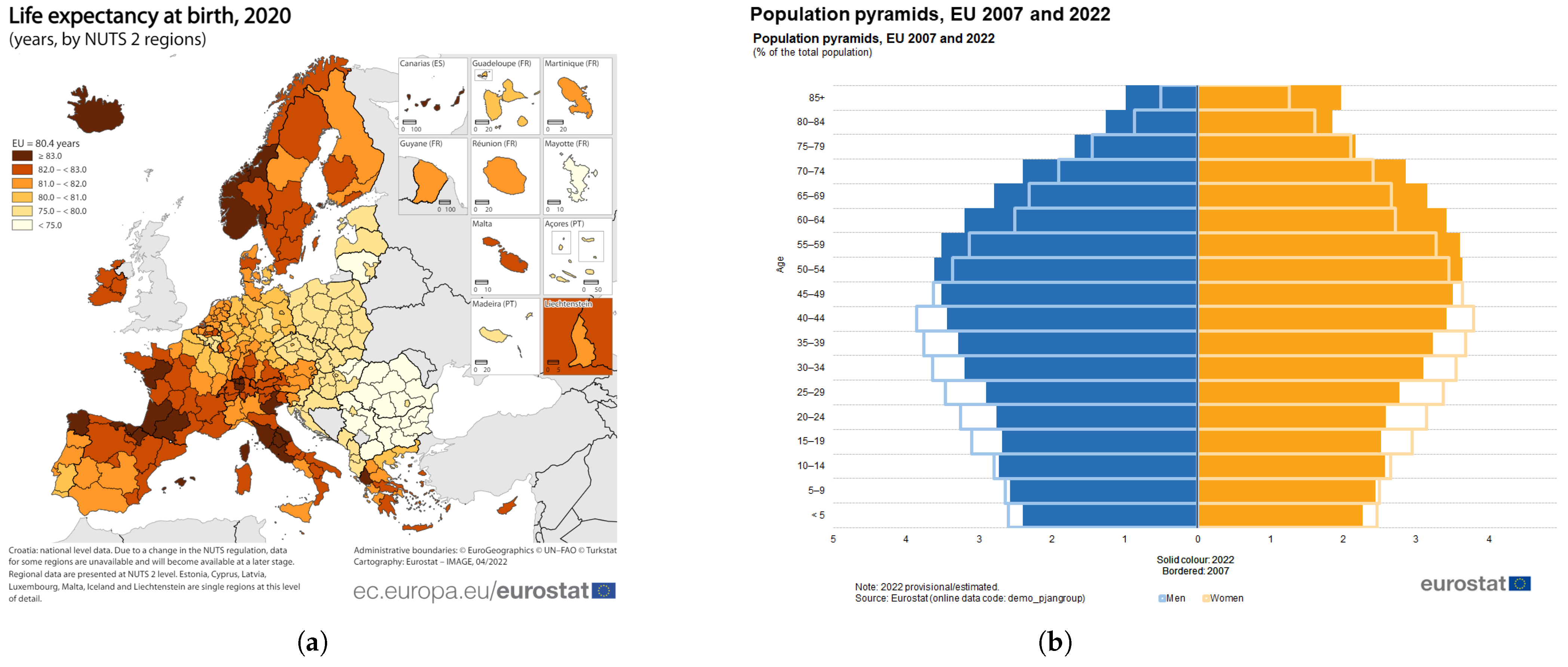
1.1. The Problem of an Aging Population in Europe
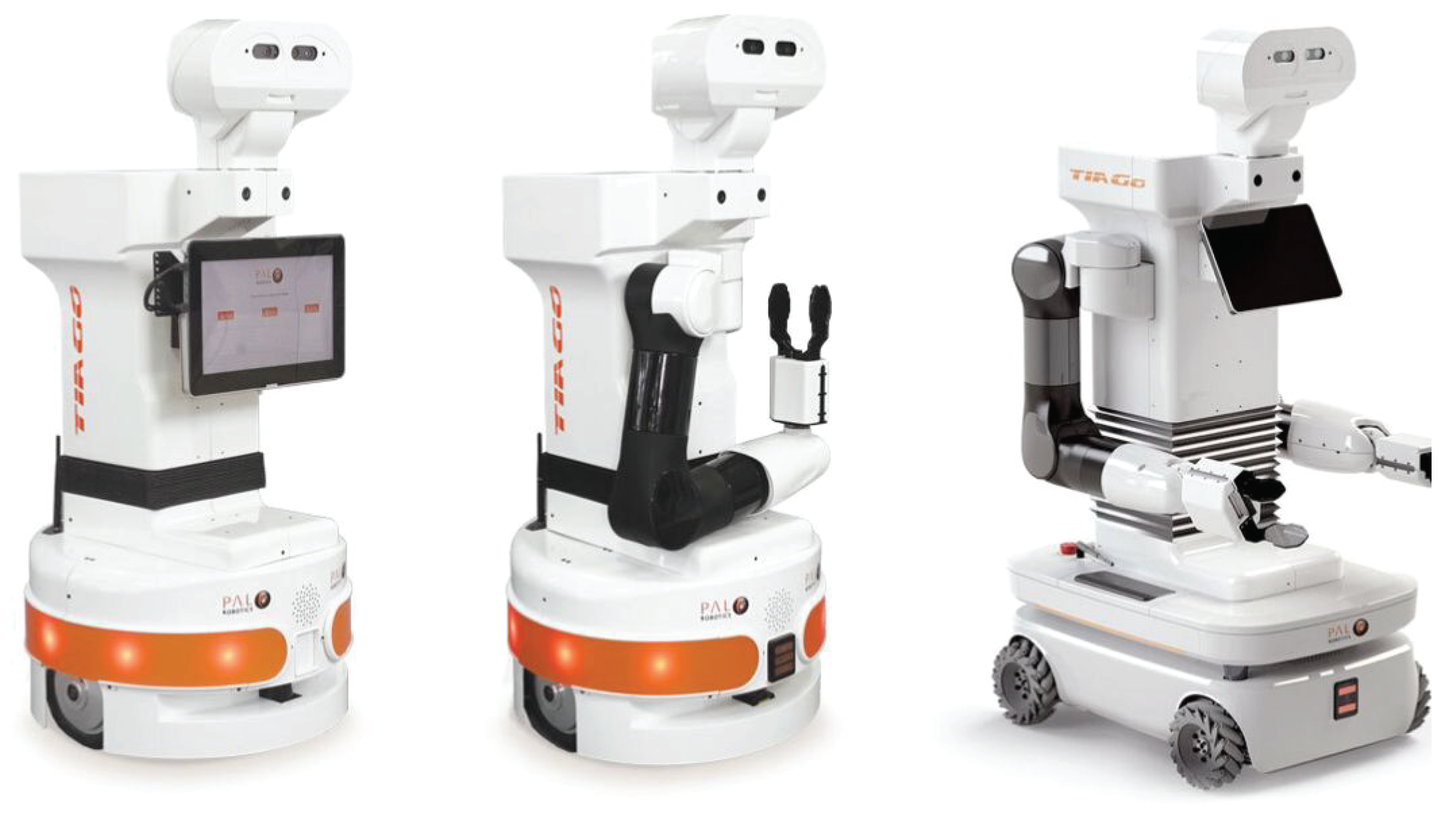
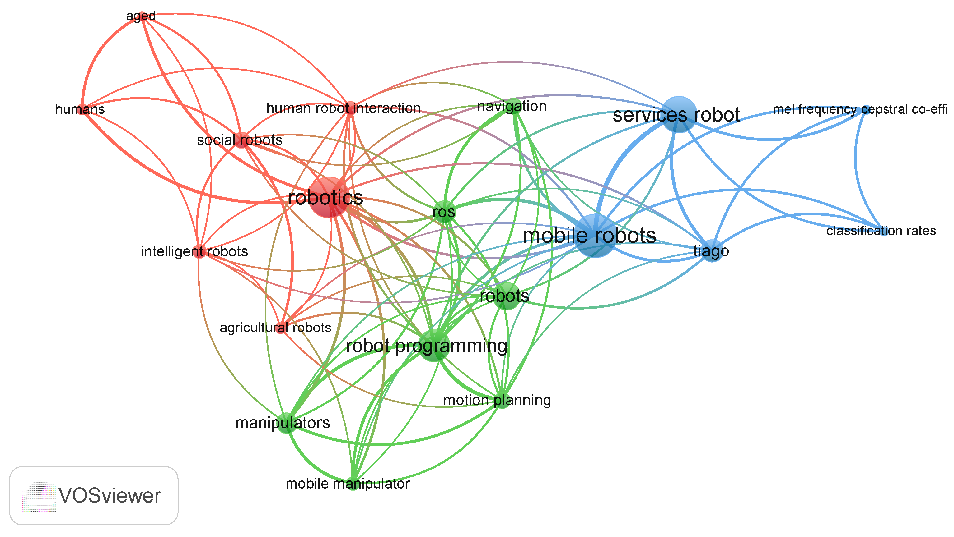
1.2. TIAGo in the Literature
- Red: Social Robotics and Human Interaction
- Blue: Mobile Robotics and Programming
- Green: Machine Learning and Robotic Services
1.3. Summary
2. Advanced Tasks in an Unstructured Environment
- The person in need of support asks the robot, either vocally or with a hand gesture, to go and retrieve an object, suppose a glass of water, located on a support surface that cannot be reached by the person;
- The robot either directly interprets the voice command or points its stereoscopic camera system towards the visual target, triggered by the voice command, interpreting its relative meaning;
- The robot scans the surrounding environment through its sensors, namely, sonars and laser range-finders, to map the space in which it operates, necessary for planning the motion of the mobile base. Furthermore, through the vision system positioned on its head, it searches for the visual target to reach and take. The target search itself is a complex task that may require moving the robot randomly if there is visual coverage of the target to be reached;
- A trajectory is automatically planned for the robot to follow to avoid colliding with fixed obstacles; along the path, the robot continues to acquire information from its surroundings through its sensors by stopping or changing its trajectory based on obstacle avoidance algorithms [20];
- Once the proximity of the target object is reached, the optimal configuration of the robot with which to grasp the target is evaluated, taking into account all the available degrees of freedom as a whole;
- Finally, the robot’s motion is planned to bring the object to and interact with the person who requested it.
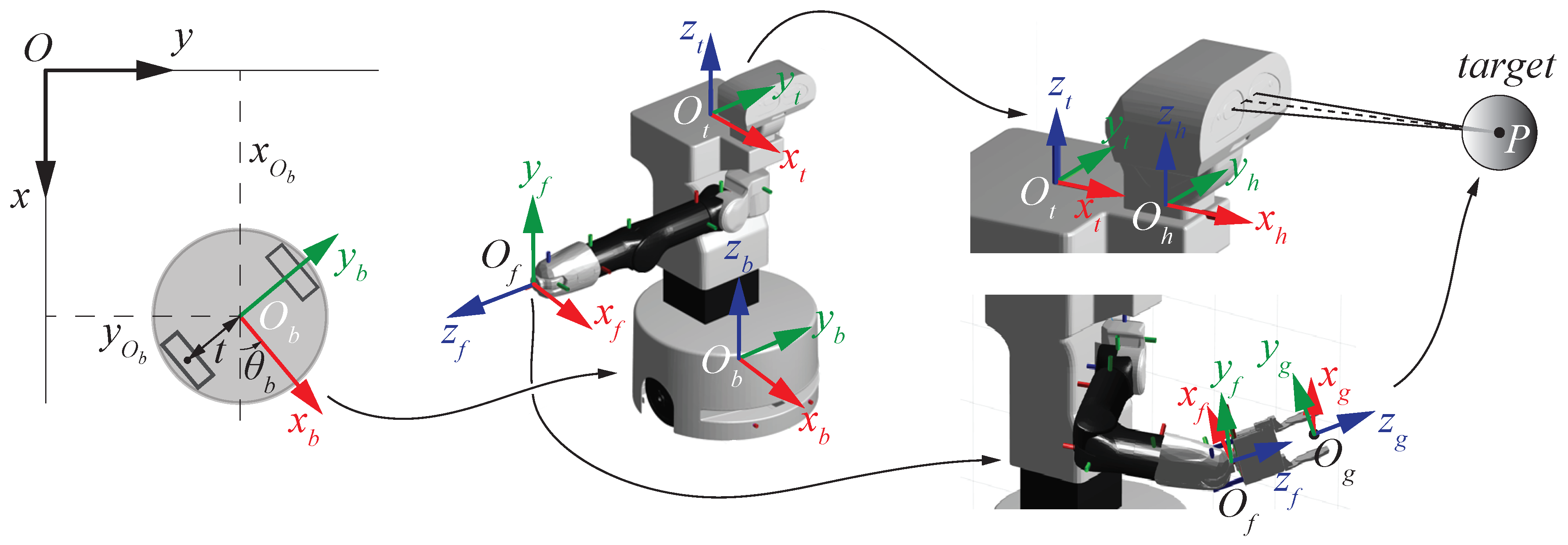
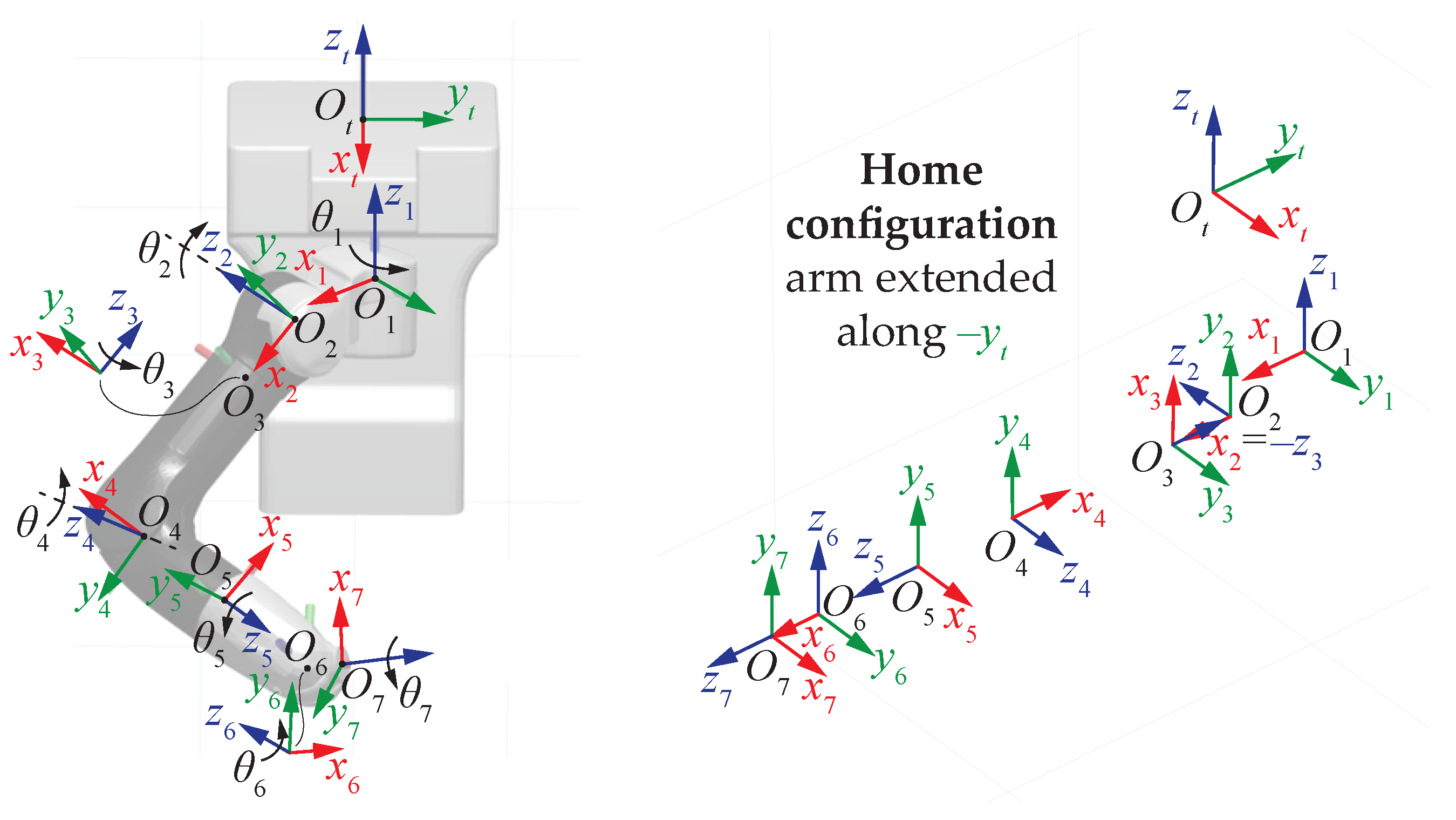
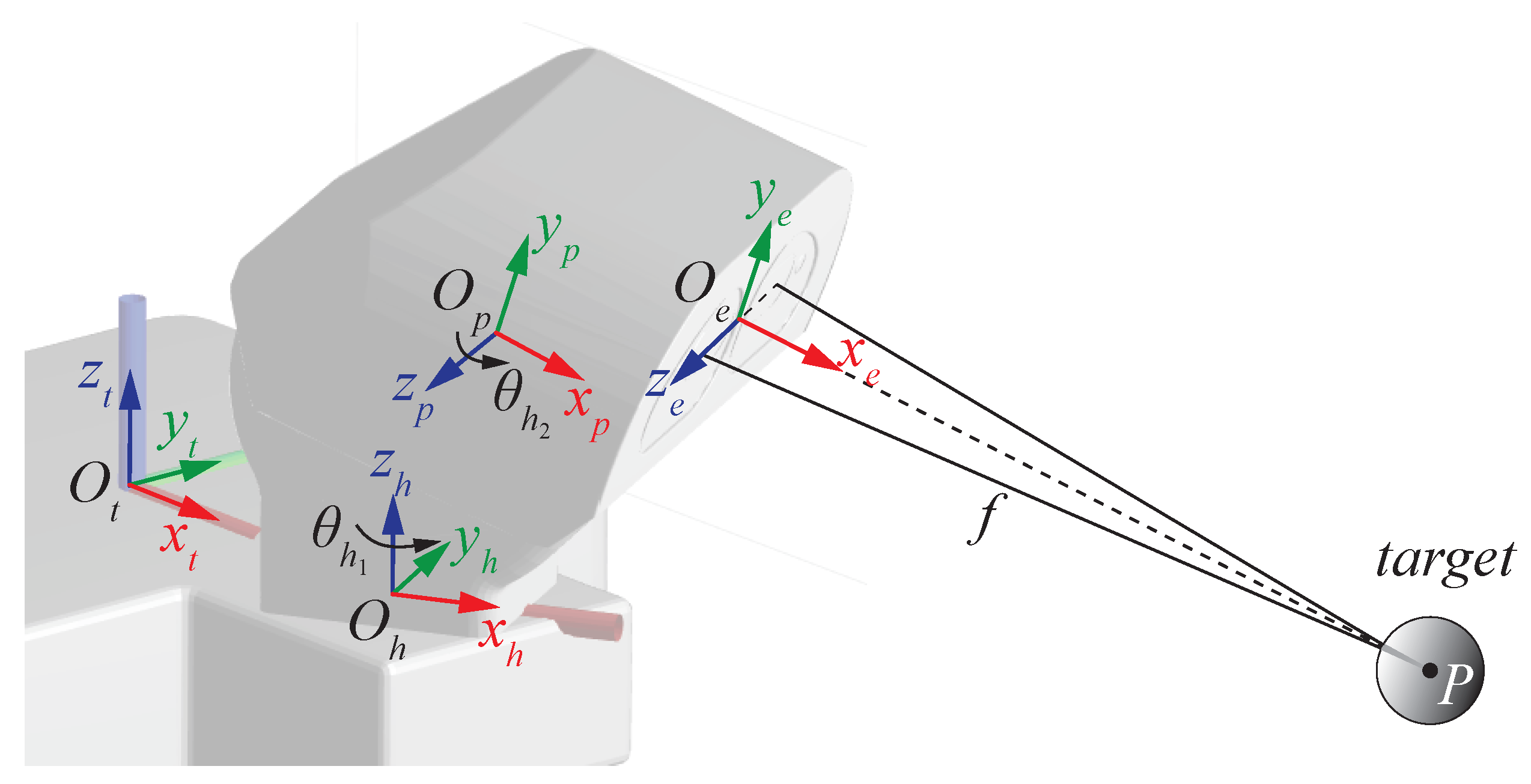
3. Position Kinematics of the TIAGo Robot
3.1. Direct Position Kinematics
3.2. Differential Kinematics
- A time derivative of vector gives directly the expression of the first three rows of the Jacobian matrix. Isolating the coordinates gathered in vector , a Jacobian matrix related to the linear velocities is obtained:
- The angular velocity results from the vector sum of all the angular velocities gained along the kinematic structure of the robot, by driving the planar rotation of the mobile base and actuating the robot joints. is the unit vector along the local z-axis around which rotations occur; thus, it follows thatwhich, in compact form, provides the expression of a Jacobian matrix, this time related to rotations:
3.3. Inverse Position Kinematics
4. Posture Optimization of the Grasping Task
4.1. Routine 1—Inverse Kinematics Routine
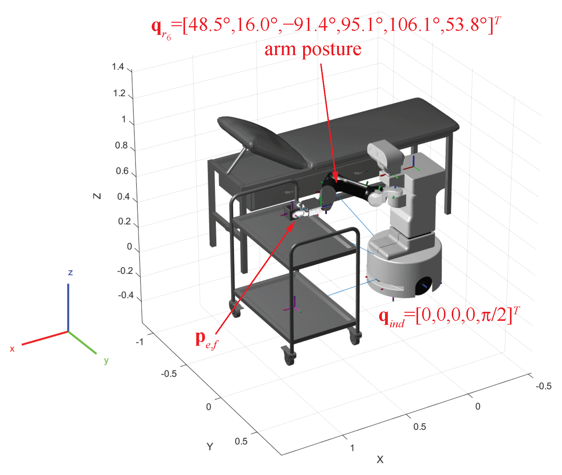
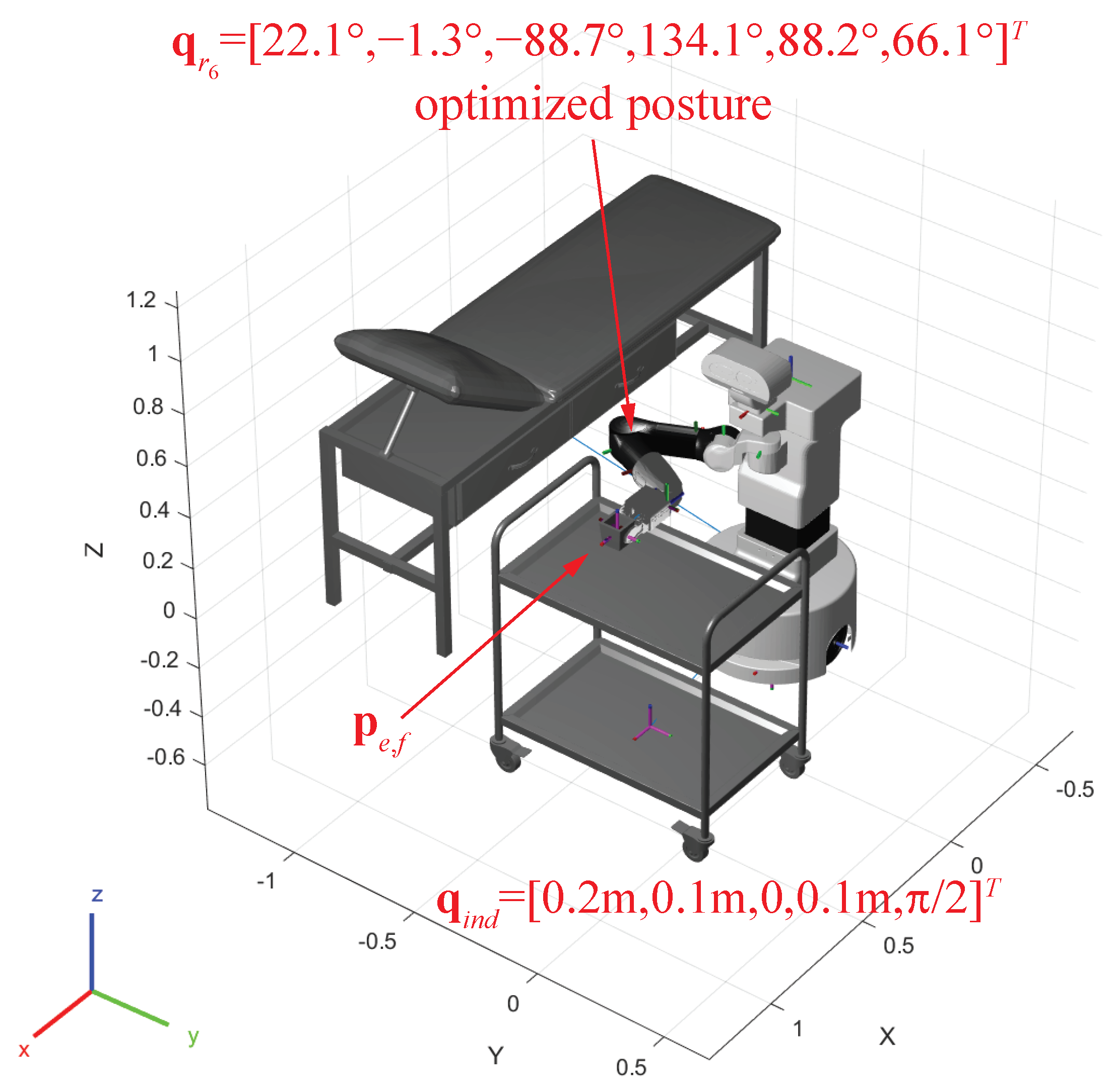
- A Cartesian pose is assigned, namely, the gripper is located on the target in the gripping configuration. In this case, as shown in Figure 7, the pose is
- A vector is chosen so that its elements fall into the intervals mentioned above. For instance, ;
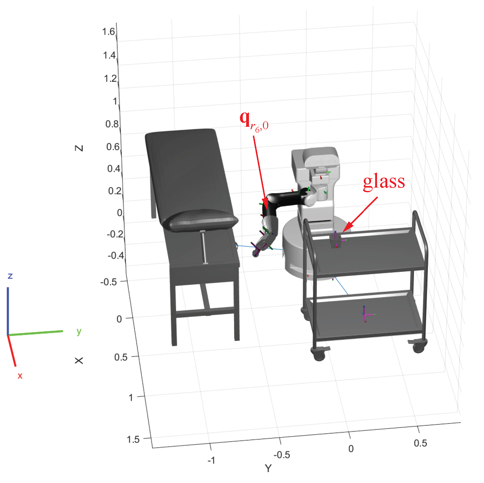
- A reference initial posture is defined. Without loss of generality, the following non-singular configuration has been chosen for the robotic arm joints, also verified visually through the Matlab Robotics Systems Toolbox, as shown in Figure 8:
- The portion of the analytical Jacobian matrix in (12) related only to the rotations in , more specifically, taking from the third column and the columns from the fifth to the tenth, is evaluated for the of step 4;
- The algorithm in (13) is updated with the Jacobian of the previous step to solve the inverse kinematics problem:where the integer k starts from 0 and gradually increases in the iterative process toward convergence, achieved only when a tolerance for both position and orientation is observed: and , with sufficiently small values for the tolerances and ;
- The new position is computed by means of the direct kinematics in (4) applied to , namely, the vector that gathers and ;
- The procedure continues iteratively until convergence, when reached. An example is presented in Figure 7, where the shown results from a given . On the contrary, the choice for is discarded from the routine and another vector is evaluated, starting again from step 2. The routine outputs the value of that verifies the tolerances of step 6.
4.2. Routine 2—Posture Optimization
- Five nested loops sweep the values of the variables in ;
- For each determined in the previous step, Routine 1 is executed in order to find the final associated with ;
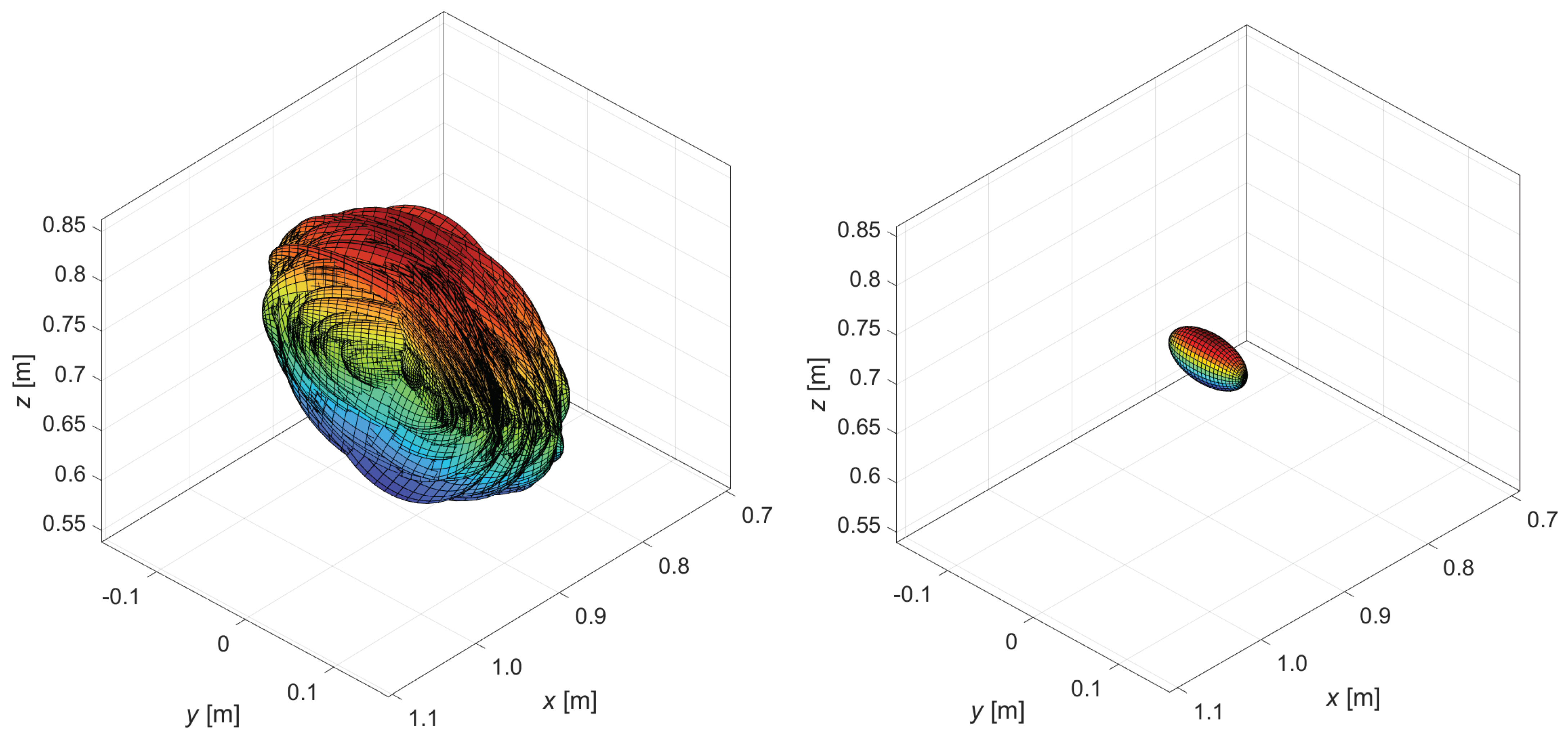
- The eigenvalues and eigenvectors of are determined, recording this information so as to know the associated manipulability ellipsoid. It is known that the eigenvectors represent the principal axes of the ellipsoid and the eigenvalues the respective dimensions;
- The index I in (14) is evaluated and recorded for that particular posture of the robot;
- The highest value obtained for I allows us to intercept the best posture in terms of velocity manipulability, to which the optimal ellipsoid corresponds;
- Similarly, for rotations, steps 3 to 5 can be repeated using matrix instead of matrix .
5. Results
6. Conclusions
Author Contributions
Funding
Data Availability Statement
Conflicts of Interest
Abbreviations
| FOCAAL | FOg Computing in Ambient Assisted Living |
| MIMIT | Ministry of Enterprises and Made in Italy |
| EU | European Union |
| COVID | COronaVIrus Disease |
| HRI | Human–Robot Interaction |
| SMS | Short Message Service |
| RUIO | Robust Unknown-Input Observer |
| ROS | Robot Operating System |
| CDPR | Cable-Driven Parallel Robot |
| AMR | Autonomous Mobile Robot |
| dof | Degrees of Freedom |
| DH | Denavit–Hartenberg |
| RGB-D | Red–Green–Blue and Depth |
References
- Tian, Y.; Li, D. The Impact of Aging on Economic Growth Based on Health Investment and Technological Innovation: An Empirical Study from China. In Proceedings of the 2020 Management Science Informatization and Economic Innovation Development Conference (MSIEID), Guangzhou, China, 18–20 December 2020. [Google Scholar] [CrossRef]
- Science, N.; Council, T. Emerging Technologies to Support an Aging Population; Technical Report NSTC-2019-1; Executive Office of the President of the United States: Washington, DC, USA, 2019.
- Peek, S.T.; Luijkx, K.G.; Rijnaard, M.D.; Nieboer, M.E.; van der Voort, C.S.; Aarts, S.; van Hoof, J.; Vrijhoef, H.J.; Wouters, E.J. Older Adults’ Reasons for Using Technology while Aging in Place. Gerontology 2015, 62, 226–237. [Google Scholar] [CrossRef] [PubMed]
- Krishnan, R.H.; Pugazhenthi, S. Mobility assistive devices and self-transfer robotic systems for elderly, a review. Intell. Serv. Robot. 2013, 7, 37–49. [Google Scholar] [CrossRef]
- Bemelmans, R.; Gelderblom, G.J.; Jonker, P.; de Witte, L. Socially Assistive Robots in Elderly Care: A Systematic Review into Effects and Effectiveness. J. Am. Med. Dir. Assoc. 2012, 13, 114–120.e1. [Google Scholar] [CrossRef]
- Ienca, M.; Jotterand, F.; Vică, C.; Elger, B. Social and Assistive Robotics in Dementia Care: Ethical Recommendations for Research and Practice. Int. J. Soc. Robot. 2016, 8, 565–573. [Google Scholar] [CrossRef]
- Coşar, S.; Fernandez-Carmona, M.; Agrigoroaie, R.; Pages, J.; Ferland, F.; Zhao, F.; Yue, S.; Bellotto, N.; Tapus, A. ENRICHME: Perception and Interaction of an Assistive Robot for the Elderly at Home. Int. J. Soc. Robot. 2020, 12, 779–805. [Google Scholar] [CrossRef]
- Remmers, P.; Fischer, N. Social Robots in Care Facilities: Reflections on Current Research and the Potential of Ethical Visions. In Frontiers in Artificial Intelligence and Applications; IOS Press: Amsterdam, The Netherlands, 2023; ISBN 9781643683751. ISSN 1879-8314. [Google Scholar] [CrossRef]
- Huang, G.; Guo, F.; Liu, L.; Taksa, L.; Cheng, Z.; Tani, M.; Zimmermann, K.F.; Franklin, M.; Silva, S.S.M. Changing impact of COVID-19 on life expectancy 2019–2023 and its decomposition: Findings from 27 countries. SSM Popul. Health 2024, 25, 101568. [Google Scholar] [CrossRef] [PubMed]
- Eurostat. Life Expectancy at Birth Down to 80.1 Years in 2021. 2023. Available online: https://ec.europa.eu/eurostat/web/products-eurostat-news/w/DDN-20230316-1#:~:text=In%202021%2C%20the%20life%20expectancy,of%20the%20COVID%2D19%20pandemic (accessed on 22 February 2024).
- Telembici, T.; Grama, L.; Rusu, C. Integrating Service Robots into Everyday Life Based on Audio Capabilities. In Proceedings of the 2020 International Symposium on Electronics and Telecommunications (ISETC), Timisoara, Romania, 5–6 November 2020. [Google Scholar] [CrossRef]
- Grama, L.; Rusu, C. Adding audio capabilities to TIAGo service robot. In Proceedings of the 2018 International Symposium on Electronics and Telecommunications (ISETC), Timisoara, Romania, 8–9 November 2018. [Google Scholar] [CrossRef]
- Grama, L.; Rusu, C. Extending Assisted Audio Capabilities of TIAGo Service Robot. In Proceedings of the 2019 International Conference on Speech Technology and Human-Computer Dialogue (SpeD), Timisoara, Romania, 10–12 October 2019; pp. 1–8. [Google Scholar] [CrossRef]
- Lach, L.; Haschke, R.; Ferro, F.; Pagès, J. Leveraging Touch Sensors to Improve Mobile Manipulation. arXiv 2020, arXiv:2010.10810. [Google Scholar]
- Muscar, L.; Grama, L.; Rusu, C. A Real-Time Warning Based on TIAGo’s Audio Capabilities. In Proceedings of the 2022 International Symposium on Electronics and Telecommunications (ISETC), Timisoara, Romania, 10–11 November 2022; pp. 1–4. [Google Scholar] [CrossRef]
- Miguel, A.; Puig, V.; Alenyà, G. Fault-tolerant Control of a Service Robot using a LPV Robust Unknown Input Observer. In Proceedings of the 2019 4th Conference on Control and Fault Tolerant Systems (SysTol), Casablanca, Morocco, 18–20 September 2019; pp. 207–212. [Google Scholar] [CrossRef]
- van Eck, N.J.; Waltman, L. Software survey: VOSviewer, a computer program for bibliometric mapping. Scientometrics 2009, 84, 523–538. [Google Scholar] [CrossRef] [PubMed]
- Sulaiman, S.; H, A.; Apurin, A.; Martinez-Garcia, E.; Magid, E. Trajectory planning and simulation of a custom mobile manipulator for door opening tasks using ROS. In Proceedings of the Advances in Robotics—6th International Conference of The Robotics Society, Ropar, India, 5–8 July 2023. [Google Scholar] [CrossRef]
- Baumgartner, J.; Petrič, T.; Klančar, G. Potential Field Control of a Redundant Nonholonomic Mobile Manipulator with Corridor-Constrained Base Motion. Machines 2023, 11, 293. [Google Scholar] [CrossRef]
- Neri, F.; Forlini, M.; Scoccia, C.; Palmieri, G.; Callegari, M. Experimental Evaluation of Collision Avoidance Techniques for Collaborative Robots. Appl. Sci. 2023, 13, 2944. [Google Scholar] [CrossRef]
- Cheah, S.K.; Caverly, R.J. Passivity-Based Pose Regulation and Jacobian-Based Force Distribution of a Cable-Driven Parallel Robot. In Proceedings of the 2021 American Control Conference (ACC), New Orleans, LA, USA, 25–28 May 2021. [Google Scholar] [CrossRef]
- Zhong, X.G.; Peng, X.F.; Zhong, X.Y.; Lin, L.X. Dynamic Jacobian Identification Based on State-Space for Robot Manipulation. Appl. Mech. Mater. 2013, 475–476, 675–679. [Google Scholar] [CrossRef]
- Kotlarski, J.; Abdellatif, H.; Heimann, B. Improving the pose accuracy of a planar 3RRR parallel manipulator using kinematic redundancy and optimized switching patterns. In Proceedings of the 2008 IEEE International Conference on Robotics and Automation, Pasadena, CA, USA, 19–23 May 2008. [Google Scholar] [CrossRef]
- He, G.; Liu, Y.; Li, C. Tightly coupled laser-inertial pose estimation and map building based on B-spline curves. Meas. Sci. Technol. 2023, 34, 125130. [Google Scholar] [CrossRef]
- Campbell, S.L.; Meyer, C.D. Generalized Inverses of Linear Transformations; Dover Publications: New York, NY, USA, 1991. [Google Scholar]
- Deo, A.S.; Walker, I.D. Overview of damped least-squares methods for inverse kinematics of robot manipulators. J. Intell. Robot. Syst. 1995, 14, 43–68. [Google Scholar] [CrossRef]
- Buss, S.R.; Kim, J.S. Selectively Damped Least Squares for Inverse Kinematics. J. Graph. Tools 2005, 10, 37–49. [Google Scholar] [CrossRef]
- Tringali, A.; Cocuzza, S. Globally Optimal Inverse Kinematics Method for a Redundant Robot Manipulator with Linear and Nonlinear Constraints. Robotics 2020, 9, 61. [Google Scholar] [CrossRef]
- Angeles, J.; López-Cajún, C.S. Kinematic Isotropy and the Conditioning Index of Serial Robotic Manipulators. Int. J. Robot. Res. 1992, 11, 560–571. [Google Scholar] [CrossRef]
- Merlet, J.P. Jacobian, Manipulability, Condition Number, and Accuracy of Parallel Robots. J. Mech. Des. 2005, 128, 199–206. [Google Scholar] [CrossRef]
- Mansouri, I.; Ouali, M. The power manipulability—A new homogeneous performance index of robot manipulators. Robot. Comput.-Integr. Manuf. 2011, 27, 434–449. [Google Scholar] [CrossRef]


| A | B | |||||||
|---|---|---|---|---|---|---|---|---|
| O | 98.5 | 0 | 0 | 0 | ||||
| 0 | −62.0 | d | 0 | 0 | 0 | 0 | ||
| 155.1 | 14.0 | −151.0 | 0 | 0 | ||||
| 125.0 | 16.5 | −31.0 | 0 | 0 | ||||
| 89.5 | 0 | 1.5 | 0 | |||||
| −20.0 | −27.0 | −222.0 | 0 | |||||
| −162.0 | 20.0 | 27.0 | 0 | 0 | ||||
| 0 | 0 | 150.0 | 0 | |||||
| 66.0 | 0 | 0 | 0 | |||||
| 0 | 0 | 0.2 | 0 | 0 | 0 | 0 | ||
| 182.0 | 0 | 0 | 0 | 0 | 0 | |||
| 5.0 | 0 | 98.0 | 0 | 0 | ||||
| 120 | 106 | 0 | 0 | 0 | 0 | 0 |
| Joint | Type | Lower Limit | Upper Limit |
|---|---|---|---|
| d | P | 0 mm | 350 mm |
| R | |||
| R | |||
| R | |||
| R | |||
| R | |||
| R | |||
| R | |||
| R | |||
| R |
Disclaimer/Publisher’s Note: The statements, opinions and data contained in all publications are solely those of the individual author(s) and contributor(s) and not of MDPI and/or the editor(s). MDPI and/or the editor(s) disclaim responsibility for any injury to people or property resulting from any ideas, methods, instructions or products referred to in the content. |
© 2024 by the authors. Licensee MDPI, Basel, Switzerland. This article is an open access article distributed under the terms and conditions of the Creative Commons Attribution (CC BY) license (https://creativecommons.org/licenses/by/4.0/).
Share and Cite
Bajrami, A.; Palpacelli, M.-C.; Carbonari, L.; Costa, D. Posture Optimization of the TIAGo Highly-Redundant Robot for Grasping Operation. Robotics 2024, 13, 56. https://doi.org/10.3390/robotics13040056
Bajrami A, Palpacelli M-C, Carbonari L, Costa D. Posture Optimization of the TIAGo Highly-Redundant Robot for Grasping Operation. Robotics. 2024; 13(4):56. https://doi.org/10.3390/robotics13040056
Chicago/Turabian StyleBajrami, Albin, Matteo-Claudio Palpacelli, Luca Carbonari, and Daniele Costa. 2024. "Posture Optimization of the TIAGo Highly-Redundant Robot for Grasping Operation" Robotics 13, no. 4: 56. https://doi.org/10.3390/robotics13040056