Article

Vision-Based Situational Graphs Exploiting Fiducial Markers for the Integration of Semantic Entities

by
Ali Tourani
1,2,
Hriday Bavle
1,
Deniz Işınsu Avşar
2,3,
Jose Luis Sanchez-Lopez
1,
Rafael Munoz-Salinas
4 and
Holger Voos
1,2,*
1
Interdisciplinary Centre for Security, Reliability, and Trust (SnT), University of Luxembourg, L-1855 Luxembourg, Luxembourg
2
Institute for Advanced Studies, University of Luxembourg, L-4365 Esch-sur-Alzette, Luxembourg
3
Department of Physics & Materials Science, University of Luxembourg, L-1511 Luxembourg, Luxembourg
4
Department of Computer Science and Numerical Analysis, Rabanales Campus, University of Córdoba, 14071 Córdoba, Spain
*
Author to whom correspondence should be addressed.
Robotics 2024, 13(7), 106; https://doi.org/10.3390/robotics13070106
Submission received: 7 June 2024 / Revised: 1 July 2024 / Accepted: 12 July 2024 / Published: 16 July 2024
(This article belongs to the Special Issue Localization and 3D Mapping of Intelligent Robotics)

Abstract

:
Situational Graphs (S-Graphs) merge geometric models of the environment generated by Simultaneous Localization and Mapping (SLAM) approaches with 3D scene graphs into a multi-layered jointly optimizable factor graph. As an advantage, S-Graphs not only offer a more comprehensive robotic situational awareness by combining geometric maps with diverse, hierarchically organized semantic entities and their topological relationships within one graph, but they also lead to improved performance of localization and mapping on the SLAM level by exploiting semantic information. In this paper, we introduce a vision-based version of S-Graphs where a conventional Visual SLAM (VSLAM) system is used for low-level feature tracking and mapping. In addition, the framework exploits the potential of fiducial markers (both visible and our recently introduced transparent or fully invisible markers) to encode comprehensive information about environments and the objects within them. The markers aid in identifying and mapping structural-level semantic entities, including walls and doors in the environment, with reliable poses in the global reference, subsequently establishing meaningful associations with higher-level entities, including corridors and rooms. However, in addition to including semantic entities, the semantic and geometric constraints imposed by the fiducial markers are also utilized to improve the reconstructed map’s quality and reduce localization errors. Experimental results on a real-world dataset collected using legged robots show that our framework excels in crafting a richer, multi-layered hierarchical map and enhances robot pose accuracy at the same time.

1. Introduction

Employing vision sensors for Simultaneous Localization and Mapping (SLAM) applications in mobile robotics can bring about several merits, including the ability to achieve rich visual information using a low-cost hardware setup, making them attractive approaches compared to Light Detection and Ranging (LiDAR)-based tools [1]. These variants of SLAM systems are known as Visual SLAM (VSLAM), as they employ visual data for map reconstruction. However, besides building a geometric map of the environment and being able to localize within it, advanced robotic situational awareness also requires the extraction of more abstract semantic information. To incorporate semantic data, approaches such as [2] enrich VSLAM with high-level information about the environment, but many of these solutions do not yet integrate valuable relational information among pertinent semantic entities. To fill this gap, 3D scene graph methodologies, such as the works introduced in [3,4,5] exhibit promising results generating meaningful 3D scene graphs from underlying SLAM data and include dynamic, semantic, and topological relationships of the situation. While these approaches still keep the different graphs separately, the authors recently proposed as a further improvement a novel approach called Situational Graphs (S-Graphs) [6], merging SLAM graphs and scene graphs into one multi-layered jointly optimizable factor graph with improved performance.
However, while the S-Graph approach only works with LiDAR sensors so far, this paper introduces a vision-based version by incorporating a VSLAM system. In addition, a vision-based approach also simplifies the detection of particular semantic entities by exploiting visible artificial landmarks. In this regard, fiducial markers as well-known artificial landmarks for Augmented Reality (AR)/Mixed Reality (MR) or robotic tasks, such as the commonly used AprilTag [7] or ArUco [8] markers, can aid in rapid information decoding and recognition. While these conventional and often paper-based fiducial markers are visible to the human eye and, hence, often found to be optically distracting in many practical applications, we recently invented iMarkers—fiducial markers made with Cholesteric Spherical Reflectors (CSRs) [9]. The use of CSRs allows for the production of mechanically very robust fiducial markers that are transparent or even shift the band of the reflected light to the UV or IR band, making them invisible for humans but still detectable for robots equipped with a specialized yet simple optical sensor. Therefore, the vision is that iMarkers will allow the future application of fiducial markers in much larger quantities in real environments without any optical distraction for humans, which finally motivates our marker-based approach in this paper. To maintain the paper’s focus on robotics and the potential of using iMarkers in visual SLAM, and to avoid going into detail about the markers and their production procedure, the authors invite the readers to explore more detailed explanations and discussions in [9].
Fiducial markers, when employed in VSLAM applications, can help to extract geometric information from the environment, and hence some VSLAM methodologies like UcoSLAM [10] and TagSLAM [11] used this potential of conventional fiducial markers to facilitate the creation of geometric maps. However, in these approaches, the performance of the localization and mapping strongly depends on the availability and detectability of the fiducial markers in the environment. To better exploit the role of fiducial markers in VSLAM, our previous preliminary work in [12] partially introduced the idea of leveraging markers mainly to extract semantic information from the environment to create meaningful 3D scene graphs, keeping the SLAM level largely independent from the markers. However, this work was constrained by its exclusive reliance on monocular cameras, and exhibited limited scalability in large-scale environments with various illumination conditions, providing great potential for improvement. Additionally, since the baseline (UcoSLAM) mainly employs the markers detected in environments to enhance feature detection and tracking and apply loop closure constraints, our version also inherits the tight marker-to-keyframe bond and is not flexible enough to generate optimizable S-Graphs.
Therefore, this paper presents a more reliable vision-based approach combining a VSLAM system with a fiducial marker detection (both conventional markers as well as iMarkers), capable of generating a three-layered S-Graph of the environment using RGB-D cameras. It tightly couples the robot poses with structural semantic entities identified by fiducial markers, namely walls, doorways, rooms, and corridors, in a multi-layered hierarchical and optimizable S-Graph. Figure 1 depicts an example of a generated three-layered graph for an indoor environment, interconnecting the robot poses with diverse structural and geometric priors about the scene. The principal contributions of this paper can be summarized as:
  • A novel approach to create three-layered optimizable S-Graphs based on fiducial markers and supporting RGB-D visual sensors;
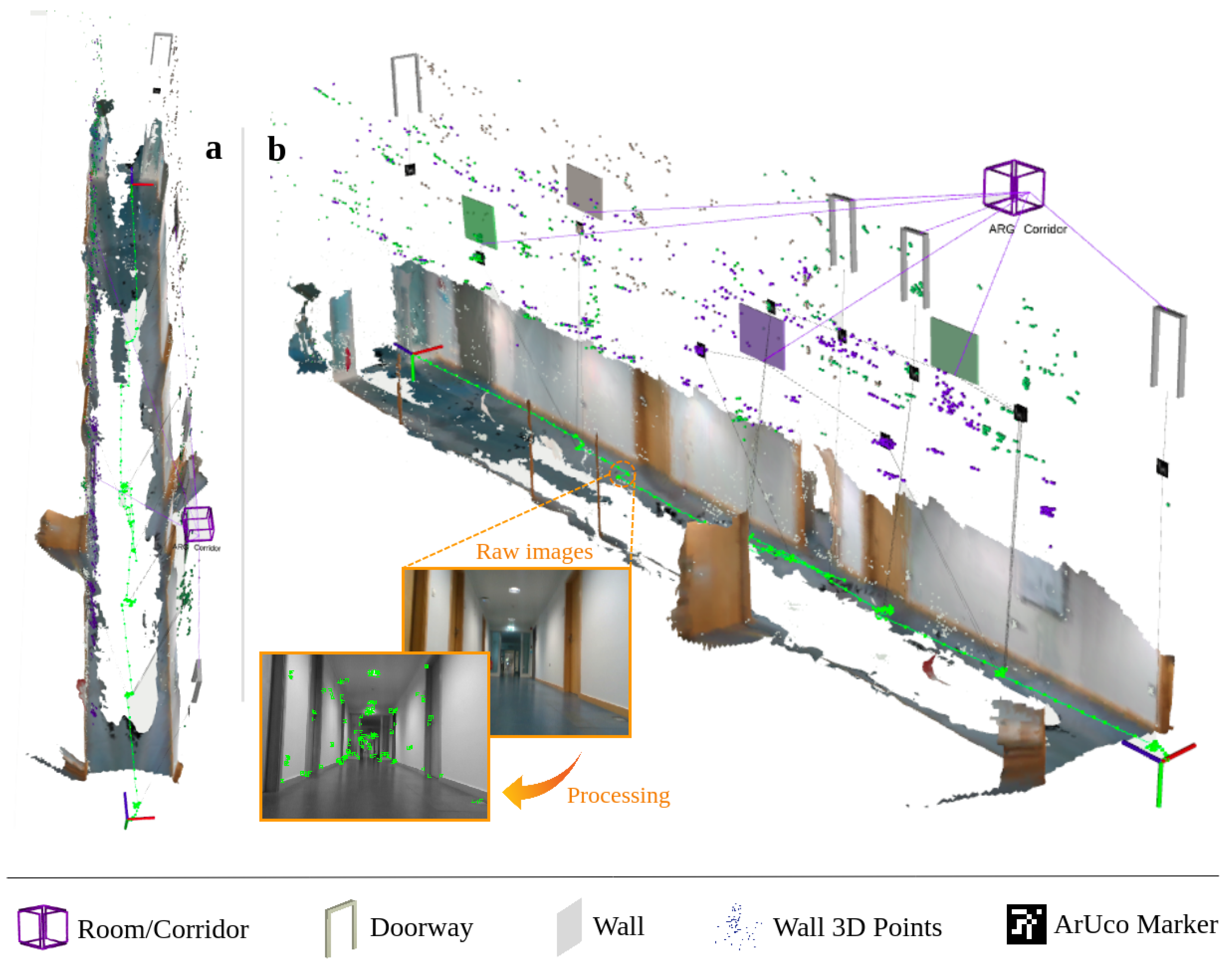
  • A new solution for map reconstruction with a hierarchical representation procedure able to extract structural-level (i.e., walls and doorways) and higher-level (i.e., corridors and rooms) semantic entities;
  • Utilizing the potential of semantic and geometric constraints imposed by fiducial markers for improving the quality of the reconstructed map and reducing localization errors;
  • Revealing the concept and potential of iMarkers for robotic situational awareness applications.
The rest of the paper is organized as follows: Section 2 explores previous efforts in the VSLAM domain, especially with respect to the use of structural-level data for improved reconstructed maps and the inclusion of fiducial markers. Section 3 details the proposed approach and its various modules. In Section 4, the evaluation criteria and an assessment of the effectiveness of the proposed method using real-world experimental data are provided. The functionality and performance of the proposed approach are discussed in detail in Section 5, and the paper finally concludes in Section 6.

2. Related Works

2.1. SLAM and 3D Scene Graphs

Over the years, VSLAM approaches have reached a higher level of maturity, and various innovative solutions have pushed the boundaries of this domain. Recent works in [13,14] surveyed the state-of-the-art in VSLAM and discussed its current trends and possible directions. Accordingly, semantic VSLAM has evolved with methods such as [15,16] estimating a geometric map and adding semantic objects in the environment for jointly optimizing the robot pose and semantic object landmarks. Sun et al. [17] proposed a deep learning-based method that extracts semantic information from the scene and performs multi-object tracking based on them. However, the system does not work in real time, and depends on a pre-processing step for segmentation. DS-SLAM [18] utilizes semantic information achieved by SegNet [19] for semantic mapping. The primary issue with DS-SLAM is the semantic segmentation limitations in covering various objects. PLPF-VSLAM [20] presents a VSLAM framework with an adaptive fusion of point-line-plane features, showing exciting results regardless of the richness of scene texture. Yang et al. [21] proposed another approach with dynamic object removal for generating static semantic maps. Although all of the above methods outperform their geometric VSLAM counterparts and can classify and map different semantic elements in the environment, they can still suffer from errors due to misidentification and the semantic elements’ pose estimation errors. Thus, adding structural/topological constraints among various semantic elements could further increase the robustness of the environmental understanding.
To mitigate the limitations of semantic SLAM techniques, 3D scene graph approaches such as [3,4,22] generate hierarchical representations of the environment by interconnecting different semantic entities with suitable relations. While the above techniques consider SLAM and 3D scene graphs as two different optimization problems, recent methods like [5,6] tightly couple SLAM graphs and 3D scene graphs for improving accuracy while generating meaningful, multi-layered hierarchical environment maps. Especially our S-Graph approach [6] directly merges the SLAM and the scene graph into a common multi-layered and jointly optimizable factor graph. As an advantage, these S-Graphs do not only offer a more comprehensive robotic situational awareness by combining geometric maps with diverse hierarchically organized semantic entities and their topological relationships within one graph, but they also lead to improved performance of localization and mapping on the SLAM level by exploiting semantic information. However, the generation of S-Graphs is so far limited to the exclusive use of LiDAR data.

2.2. Fiducial Markers and Marker-Based SLAM

While the aforementioned approaches for SLAM or semantic data extraction are based on natural visual features or objects of the environment, fiducial markers, which are intentionally added to the environment, can also serve as valuable tools for achieving enhanced scene understanding and mapping. Fiducial markers are used in robotics and Augmented Reality (AR) to encode information about objects on which they are applied, revealing the nature of each object and of the surrounding context to read-out devices. They can be classified into non-square (designed as circles [23,24,25], point sets [26,27], or arbitrary visual patterns [28,29,30]), square (or matrix-based, such as ARToolkit [31], AprilTag [7], and ArUco [8]), and hybrid variations (such as DeepTag [32] and DynaTags [33]).
However, these conventional markers are visually invasive and optically distracting if they are placed in a normal environment. Furthermore, they are often printed on pure paper, which does not permit an application over a longer period of time without mechanical abrasion. Therefore, we recently introduced iMarkers, which are based on an innovative optical material called Cholesteric Spherical Reflectors (CSRs) [9]. CSRs are ∼0.1 mm diameter spheres of polymerized liquid crystal, exhibiting unique reflective properties. These make iMarkers invisible to humans, but not to adequately designed sensors, which can detect and read them even in visually complex and dynamic environments. Designed as flexible and flat foils that can be applied to hard or soft surfaces, iMarkers exhibit omnidirectional retro-reflectivity in a narrow wavelength band with circular polarization. This enables machine detection and readout from any direction, night or day, without false positives [9]. The iMarkers can be designed to be transparent, as shown in Figure 2, but the CSR reflection band can also be tuned outside the visible spectrum, operating in the near-infrared (IR) or near-ultraviolet (UV) band, hence making the iMarkers undetectable by the human eye. Therefore, iMarkers would be non-intrusive and avoid attracting visual attention. While the iMarkers are totally novel from a material science perspective, the encoded geometric patterns we designed so far are the same as in the conventional ArUco markers, hence the same ArUco detection and pose estimation algorithms can also be used for the iMarkers. Further details on the optical sensors and computer vision methods we developed for the detection and readout of the iMarkers can be found in [9].
Assuming that conventional fiducial markers are placed in the environment, the literature contains several approaches that explicitly use them in VSLAM. In this regard, UcoSLAM [10] is a marker-based VSLAM solution that utilizes visual features obtained from natural landmarks and ArUco markers. It works in keypoint-only, marker-only, and mixed modes, and is equipped with a marker-based loop closure detector, which requires placing distinct fiducial markers in the environment. TagSLAM [11] is another VSLAM approach that uses AprilTags to perform SLAM tasks. However, the system runs in marker-only mode and must constantly see the markers for localization and tracking stages. It should be noted that all of the mentioned approaches are focused on creating geometric maps and marker-based loop closure detection, and they do not employ the potential of fiducial markers for decoding semantic information. Thus, the preliminary work [12] of the authors of this paper introduced the idea of using ArUco markers for the designation of semantic entities in the environment, while a modified version of UcoSLAM (referred to as Semantic UcoSLAM) has then been leveraged for SLAM and the detection of the marked semantic entities. The primary drawbacks of this method were its low versatility (it is limited to monocular cameras), lack of scalability in larger environments, and tight marker-to-keyframe constraint inherited from the baseline, which avoids generating optimizable S-Graphs. Accordingly, the work introduced in this paper extends this preliminary approach by utilizing fiducial markers (including conventional as well as iMarkers based on the ArUco pattern) to generate a three-layered optimizable hierarchical S-Graph incorporating in particular semantic objects with appropriate relational constraints, as detailed in the following.

3. Proposed Method

The presented framework is built upon ORB-SLAM 3.0 [34], and aims to provide more comprehensive reconstructed maps and their multi-level topological graph representations with semantic information derived from fiducial markers. The system takes advantage of a proper multi-threading architecture that successfully maintains the frame rate of the input and performs in real time. Moreover, it is implemented using Robot Operating System (ROS) to facilitate developing a modular design with simple integration, scalability, and communication potentials. Since the first robotic applications of our proposed approach are related to buildings, e.g., the autonomous monitoring of construction sites or the surveillance of indoor environments for security tasks, this paper restricts the set of included semantic entities to those that are the most important to describe the structure of building environments. Herein, walls and doorways are considered lower structural-level semantic entities that are annotated with a fiducial marker (ArUco-like conventional or iMarker), while rooms and corridors are considered higher-level semantic entities composed of the lower ones. However, the overall approach is, in principle, open to including any further semantic entities, which simply need to be annotated, in this case, with a fiducial marker and included from a mathematical point of view in the framework as described in the following.
All data are represented in the aforementioned S-Graph format, i.e., a common optimizable factor graph that merges the SLAM graph with the hierarchically ordered semantic information. Our framework computes structural-level elements’ spatial positioning, leveraging fiducial markers affixed to them instead of relying on LiDAR-based odometry readings and planar surface extractions. It reconstructs a semantic map with hierarchical representations in the presence of ArUco-like markers and a database of high-level information about markers’ affiliations with objects. The current framework version supports the RGB-D sensor and is extendable to monocular and stereo cameras, and leads to reconstructed map richness compared to the purely geometric maps generated by traditional VSLAM frameworks. In this paper, the focus is on the real-time generation of the S-Graph and the related algorithms and less on the lower-level visual detection of the different included marker types, so we refer to [9] regarding the sensors and visual detection of iMarkers, if present in the scene.
Figure 3 depicts the pipeline of the proposed methodology and its constituent components. The framework benefits from a multi-thread architecture for processing data, including tracking, local mapping, loop and map merging, and marker detector. The operation commences by processing the frames captured by an RGB-D camera and conveying them to the tracking module, where Oriented FAST and Rotated BRIEF (ORB) features and ArUco markers are extracted. The outcome of this module contains KeyFrame candidates with pose information, 3D map points, and possibly fiducial markers. If the tracking module decides that the current frame should be a KeyFrame, the local mapping module triggers to add the KeyFrame and points to the map, refining the map structure. Concurrently, the framework is being used to identify structural-level entities, including walls and doorways, and higher-level ones, containing corridors and rooms. The mentioned process takes place by leveraging pose information obtained from fiducial markers and a pre-defined semantic perception dictionary housing real-world data about the environment. Extracted semantic information is a resource for enhancing local Bundle Adjustment (BA) and KeyFrame culling the local mapping. It should be mentioned that the Room local BA module in local mapping is designed to connect the recently mapped walls and doorways within the current local KeyFrames to a newly detected room or corridor. Accordingly, it acts as a complementary module to the “local BA” to trigger the optimization process involving the lately mapped structural elements and incorporate them into a high-level semantic entity, imposing new constraints. Thus, when added to the factor graph, the poses of these elements with respect to each other (such as the relative positions and orientations of walls and doorways within a room) provide valuable context that aids in further refining the map. The next impact is adjusting the poses of the KeyFrames and map points. The system constantly cooperates with an enhanced version of Atlas (the map manager module of ORB-SLAM 3.0) for establishing connections among disparate maps, representing the currently existing map (i.e., active) and previously generated maps (i.e., non-active). Loops and shared regions are detected within the active map and maps archived in Atlas, in the loop and map merging module. Finally, and in the case of loop detection and correction, the global bundle adjustment module is invoked to refine the constructed map further.

3.1. Fundamentals

The proposed method introduces four central coordinate systems at time t: the odometry frame of reference O, the camera coordinate system C t , the marker coordinate system M t , and the global coordinate system G t . The vision sensor captures a set of frames F = { f } , with each frame f = { t , T , δ } containing the camera pose T S E ( 3 ) acquired through the transformation of C t to G t , as well as intrinsic camera parameters δ . Each frame f undergoes sub-sampling into an image pyramid and is processed by ORB feature extractor to obtain a set of key points for selecting KeyFrames, denoted as K = { k } F . These KeyFrames contain feature points P = { p } and fiducial markers M = { m } (regardless of their type) used for detecting structural-level and semantic entities. A feature point p = { x , v , d ^ } is characterized by its corresponding 3D position x R 3 , viewing direction v R 3 , and descriptor d ^ . On the other hand, each marker m = { i d , t , s , p } holds unique ArUco marker identifier m i N , length s R , and pose p S E ( 3 ) derived from the transformation of M t to G t . Consequently, the final representation of the reconstructed map of the environment E is defined as follows:
E = { K , P , M , W , D , R }
where W = { w } encompasses the detected walls within the environment, in which each wall w = { t , q , m w } holds the wall equation q R 4 and the list of attached markers m w M . D = { d } comprises the doorways found in the environment, where each doorway d = { t , m d , p } contains attached marker m d M and pose p S E ( 3 ) computed from M t to G t transformation. Finally, R = { r } represents the set of rooms/corridors present in the environment, each r = { t , r c , r w } with a center point r c R 3 and a list of walls r w W = ( w 1 . . . w n ) | w i N that constitute the boundaries of the room or corridor.

3.2. Structural-Level and Higher-Level Semantic Entities

Reconstructing a rich semantic map of the environment incorporating the mentioned entities entails employing diverse methodologies, which will be discussed in this section. In the proposed approach, fiducial markers (which could be conventional or iMarkers) thus play a vital role, and their synergy with the system, in conjunction with the semantic perception module, aids in recognizing the entities of interest. Accordingly, the proposed framework takes advantage of fiducial markers, not only to add geometric constraints for map creation but also to enrich them with desired building-related semantic entities acquired with the aid of markers. It is worth emphasizing that the semantic perception dictionary encodes exclusively the marker-ids corresponding to rooms and doorways, obviating the need for any supplementary pose information of the labeled objects to be incorporated.
Markers. Fiducial markers are crucial reference points in our framework, enabling the system to interpret and contextualize semantic data in the environment. It has to be mentioned that the fiducial markers contain no direct information about the characteristics of the labeled items, such as pose in the global reference and width/height. Owing to their distinctive textures and the capacity to compute pose information ( p S E ( 3 ) ), fiducial markers are primary sources of information in the proposed work for identifying and labeling targeted semantic entities, i.e., walls and doorways. Each marker m i in G t is constrained by the KeyFrame K i observing it, which can be formulated as:
c m i ( G K i , G m i ) = L m i   G K i   G m i 1 Λ m ˜ i 2
where   L m i represents the locally observed fiducial marker’s pose, ⊞ and ⊟ refer to the composition and inverse composition, is the Mahalanobis distance, and Λ m ˜ i is information matrix associated with m ˜ i .
Walls. The procedure employed to identify wall surfaces, which serve as the planar substrates on which ArUco markers and feature points features are situated, relies on pose information derived from detected markers. Wall detection occurs whenever a fiducial marker is visited within the current KeyFrame. Hence, by accessing the real-world environment data obtained from the semantic perception module, in cases where the marker’s identifier is not found within the list of markers associated with doorways, the planar equation of the wall is calculated using the poses of the attached marker and the surrounding map points. It should be noted that this work assumes that all fiducial markers are affixed directly to the walls in an environment. Consequently, the equations characterizing these walls are obtained based on the poses of the markers attached.
Each wall w i in G t is represented by   G w i =   G n i   G d , where   G n i = n x n y n z T denotes the normal vector of the wall and d represents the distance of the wall w i from the origin in the global coordinate system. The vertex node of the wall within the graph is denoted as   G w i = [ G ϕ , G θ ,   G d ] , where   G ϕ and   G θ represent the azimuth and elevation angles of the wall in the global coordinate G t , respectively. Consequently, the cost function associated with each marker   G m i affixed to the wall   G w i can be calculated as follows:
c w i ( G w i , G m i ) = [ M δ ϕ w i m i , M δ θ w i m i , M d w i ] T Λ w ˜ i 2
where   M δ ϕ w i m i represents the disparity between the azimuth angle of wall w i and its attached marker m i in M t ,   M δ θ w i m i denotes the difference in elevation angles between the two. In contrast,   M d w i signifies the perpendicular distance separating the wall from the marker. This distance should ideally be zero for given marker–wall pairings.
Corridors (Two-Wall Rooms). Our framework leverages an adapted version of the “room segmentation” methodology originally presented in S-Graphs, wherein markers are employed for detecting walls belonging to rooms. In this context, a corridor is defined as a room in the environment in which two parallel walls are labeled with ArUco markers. Due to the complexities associated with detecting rooms with diverse layouts, this work extends its definition to include rooms with inaccessible walls as corridors.
A corridor   G r x = [   G w x a 1 ,   G w x b 1 ] encompasses wall planes aligned with the x-axis. To calculate the center point of a corridor   G r x i , the two equations representing the x-wall planes are employed in conjunction with the center point   G c i of the marker m i in the following manner:
  G k x i = 1 2 |   G d x a 1 | ·   G n x a 1 |   G d x b 1 | ·   G n x b 1 + |   G d x b 1 | ·   G n x b 1
  G η x i =   G k ^ x i +   G c i [   G c i ·   G k ^ x i ] ·   G k x i ^
where   G η x i represents the center point of the corridor   G r x i and   G k ^ x i is derived from   G k ^ x i =   G k x i /   G k x i . The center point   G c i of the marker is determined based on the marker’s pose within the G frame. Notably, the computation of the center for a two-wall room in the y direction follows a similar procedure. The cost function to minimize the corridor’s vertex node and its corresponding wall planes is defined as follows:
c r x i (   G r x i ,   G w x a 1 ,   G w x b 1 ,   G c i ) = t = 1 , i = 1 T , K   G η ^ x i f (   G w ˜ x a 1 ,   G w ˜ x b 1 ,   G c i ) Λ r ˜ i , t 2
where f (   G w ˜ x a 1 ,   G w ˜ x b 1 ,   G c i ) is a mapping function that associates the wall planes with the corridor’s center point.
Rectangular Rooms (Four-Wall Rooms). In the scenario where a room in the environment consists of four walls, each labeled with ArUco markers (i.e., two pairs of perpendicular labeled walls), the room is represented as   G r i = [   G w x a 1   G w x b 1   G w y a 1   G w y b 1 ] . The center point   G ρ i of the room   G r i is computed using the following equation:
  G q x i = 1 2 |   G d x a 1 | ·   G n x a 1 |   G d x b 1 | ·   G n x b 1 + |   G d x b 1 | ·   G n x b 1
  G q y i = 1 2 |   G d y a 1 | ·   G n y a 1 |   G d y b 1 | ·   G n y b 1 + |   G d y b 1 | ·   G n y b 1
  G ρ i =   G q x i +   G q y i
where the equation is positive if | d x 1 | > | d x 2 | . The cost function to minimize the room’s vertex node and its corresponding wall planes is defined as follows:
c ρ (   G ρ ,   G w x a i ,   G w x b i ,   G w y a i ,   G w y b i ) = t = 1 , i = 1 T , S   G ρ ^ i f (   G w ˜ x a i ,   G w ˜ x b i ,   G w ˜ y a i ,   G w ˜ y b i ) Λ ρ ˜ i , t 2
where f (   G w ˜ x a i ,   G w ˜ x b i ,   G w ˜ y a i ,   G w ˜ y b i ) is a mapping function that associates wall planes with the room’s center point.
Doorways. In this case, the pose information of ArUco markers placed on a door frame is employed to define the doorway in the map. The procedure involves visiting fiducial markers present in the current KeyFrame and verifying their association with doorways through the utilization of the semantic perception module. Once confirmed, the pose of the visited marker is designated for the doorway.
Accordingly, the cost function for each doorway d i in G t and its corresponding room (or corridor)   G r i is computed as follows:
c d i ( G d i , G r i ) =   G δ ^ d i , r j f ( G d i , G r i ) Λ d ˜ i , t 2
where   G δ ^ d i , r j represents the relative distance between the door and the room and f ( G d i , G r j ) maps the relative distance among their nodes.

3.3. The Final S-Graph

The structure of the final S-Graph generated by our framework is depicted in Figure 4. Accordingly, the primary tracking information sources are located in the KeyFrames, which contain geometric data and pose information of objects, including 3D points and visited ArUco markers. The constraints among the mentioned objects guarantee proper computation of the odometry and loop closure detection. Structural-level entities, including walls and doorways, are linked to constraints associated with the mapped fiducial markers and establish next-level constraints with higher-level entities, including rooms and corridors.

3.4. Inclusion of iMarkers

As conventional fiducial markers may face problems with visual clutter, they can be seamlessly replaced with iMarkers in our framework. Since the production of our iMarkers is still in an experimental stage, larger amounts of iMarkers could not yet be produced and included in the assessment. However, we applied a combination of conventional printed and a few transparent iMarkers, all with ArUco pattern, for these experiments here. The project’s final future vision is to label desired semantic entities with invisible iMarkers only instead of using printed ones. The performance and usage of the mentioned markers in robotics will be evaluated in detail in Section 4.

4. Evaluation

To evaluate the performance and robustness of the proposed method compared to other existing frameworks, various experiments have been performed using the proposed approach, UcoSLAM [10], as a well-known marker-based method, our previous methodology known as Semantic UcoSLAM [12], and ORB-SLAM 3.0 [34] as the baseline and a reliable VSLAM methodology. It should be noted that since the proposed approach is more marker-based than a fully semantic VSLAM, evaluating against existing semantic VSLAM methodologies can be unfair. The reason lies in the fundamental dissimilarities in the context, where semantic VSLAM requires more computational resources (mainly GPU-dependent computer vision methods), and is designed to extract a broader range of semantic information. Additionally, and due to less noisy outputs of LiDAR sensors compared to vision-based sensors, S-Graphs+ [6], as a LiDAR-based framework, has been used to produce ground truth data. A computer equipped with an 11th Gen. Intel® Core™ i9 @2.60GHz processor and 32 GigaBytes of memory was used for the evaluation mentioned.

4.1. Evaluation Setup

For evaluating the performance of the proposed method in real-world conditions, a 3D LiDAR sensor and an Intel® RealSense™ Depth Camera D435i were mounted on legged robots, including Boston Dynamics Spot® and Unitree Go1 (shown in Figure 5). The mounted camera captures the scene viewed by the robot at a rate of 25 frames per second (fps). The robots collected data from sensors while traversing various indoor environments with different room and corridor configurations. Each wall and door of the rooms and corridors were labeled with 8 cm × 8 cm ArUco-like markers, and the unique identifiers of the markers were stored in a database to feed the proposed method (i.e., the semantic perception module in Figure 3). As previously mentioned, the environment for data collection has been prepared using a combination of printed ArUco markers and a few transparent iMarkers. Accordingly, the characteristics of the collected datasets are presented in Table 1.

4.2. Experimental Results

Accuracy. To validate the accuracy of the proposed method in comparison to its baseline and ground truth, ATE measurements have been employed in this paper. Regarding the evaluation results presented in Table 2, it becomes evident that our approach outperforms its baseline counterpart and other frameworks across various scenarios. This enhancement can be attributed to the proposed method’s ability to introduce new constraints to the map by associating structural-level and semantic entities. It is noteworthy that the improvements are particularly pronounced in comparison to the two marker-based methodologies. While on Seq-02 and Seq-05, ORB-SLAM 3.0exhibits slightly better performance than our method, the difference is negligible (i.e., <3 cm). This discrepancy could be due to the noisy detection of the fiducial markers as the primary source of semantic information in real-world scenarios with changing light conditions. However, it is important to emphasize that the proposed approach, in addition to improving ATE in most cases, can generate a three-layered situational graph of the environment. Accordingly, Figure 6 depicts some qualitative results alongside the accuracy of the proposed approach against the LiDAR-based benchmark. The qualitative results in sub-figures A and C show that the proposed approach can reconstruct rich maps of the environments by mapping the detected structural-level semantic objects with the aid of fiducial markers and calculating the presence of high-level semantic entities, including rooms and corridors. It also represents the connection among the mentioned entities in the form of the hierarchical scene graphs, described in Figure 4.
The performance of the iMarkers. To verify the applicability and potential of our described iMarkers for the first time in robotics, the door frames in Seq-06 were labeled with a prototype of transparent iMarkers. The reconstructed map using the iMarkers is depicted in Figure 6. Given that the sole distinction between iMarkers and conventional printed ArUco markers lies in the detection step, the resulting semantic map remained unaltered. The authors believe this will provide proper room for future investigation on utilizing such iMarkers in their future works.
Execution time and computational cost. As mentioned in Section 4.1, data instances used for evaluation were recorded in 25 fps. Validation results on the dataset showed that the designed system, thanks to its multi-threaded architecture shown in Figure 3, could efficiently handle the computational load and continue performing in real-time at 25 fps. It should be noted that the computational hurdle is not evenly distributed across all the framework modules. For instance, extracting ORB features in the tracking module is performed in real-time, while in parallel, an ArUco marker detector seeks markers in each frame and integrates the detected marker poses into the framework via ROS-based communication. As a module with intensive calculations, local mapping and its underlying optimization processes are triggered periodically based on new KeyFrame detections. However, it operates asynchronously with respect to the tracking module and without directly influencing the frame rate. Identifying structural- and higher-level entities and querying the semantic perception dictionary are also not computationally intensive, and require 10–15% of the processing time. Finally, the most computationally demanding modules are loop and map merging and global bundle adjustment, which operate less frequently and asynchronously, triggered only when significant map updates are necessary.
Moreover, in terms of the required processing time, experiments showed that all the evaluated frameworks in Table 2 work in real-time (and almost in real-time) on the utilized computer. In this regard, ORB-SLAM 3.0 functions faster than others, in the range of 33 to 38 milliseconds per frame (ms/frame). The proposed framework requires more time (an average of 46 ms/frame) due to adding new constraints and calculations, but it still guarantees low latency rates during processing. Similar outcomes are obtained for UcoSLAM and its semantic version, with the difference that the baseline is almost 1.4× faster due to less processing overhead. The point to be emphasized here is the trade-off between map richness (and, therefore, supplying improved situational awareness capabilities) and processing time in different applications where a slightly higher processing load is worthwhile acquiring improved functionality.

5. Discussions

Regarding the evaluation results and comparing them with other marker-based state-of-the-art works, the authors would like to highlight the innovative nature of the methodology presented in this paper. The proposed approach employs fiducial markers to enhance map reconstruction and scene representation in a visual SLAM framework by avoiding the significant computational overhead of integrating computer vision and deep learning-based scene understanding modules. By concentrating only on scene elements augmented with fiducial markers, including “quasisemantic structural-level objects” (i.e., walls and doorways) and “calculable higher-level semantic entities” (including corridors and rooms), the framework simplifies the interpretation process to paramount components. This selective scene comprehension enables better digital twin creation and enriched scene graph generation, ultimately producing more informative maps for robotic tasks where situational awareness is crucial. For instance, in a task like navigation or path planning, the proposed framework generates maps with detailed environmental information, including the presence (and, if so, the locations) of walls, doorways, and corridors. This offers a substantial advantage over purely geometric maps created using classic methods like ORB-SLAM 3.0 or UcoSLAM, which may require more semantic depth for a robot performing path planning.
On the other hand, despite not utilizing extensive computer vision frameworks for semantic scene segmentation or object detection/tracking, the introduced method derives the required semantic information from marker poses and unique identifiers to enhance map reconstruction. Accordingly, it allows rapid mapping of objects and the imposition of additional constraints, leading to higher levels of richness and usability of the reconstructed maps without heavy computational demands. Needless to say, the approach is designed to map any labeled static object for rapid and cost-effective map enrichment, supporting more robust and situationally aware robotic applications.
Another important note is that the proposed approach is dependent on the presence of markers, which could pose limitations in environments where marker placement/detection is challenging. However, the proposed solution offers a deliberate trade-off between “simplicity” and “performance” while guaranteeing richer reconstruction maps with higher estimated robot poses. Although the demand for detectable markers may restrict application in specific scenarios, the method offers many benefits in environments where markers can be appropriately placed.
Considering the significance of the framework’s scalability in working fine in larger environments and the simplicity of covering more semantic entities (items labeled with fiducial markers) to generate richer maps, the proposed framework is built using ROS, which inherently supports scalability through its modular architecture. It also provides distributed processing so the designed nodes (modules) handle diverse tasks and maintain parallel execution. Accordingly, the proposed method scales efficiently with increasing the environment’s scope and complexity. Observations while running the experiments imply that the framework’s multi-threaded architecture and fine-tuned workload division can lead the proposed approach to maintain its real-time performance.
Finally, the authors would like to underscore that the proposed approach is a marker-based VSLAM solution inspired by S-Graphs. While the LiDAR-based version is more accurate, comparing it directly to the proposed VSLAM version is unjust due to the fundamental differences between the sensing modalities. On the other hand, the proposed framework is cost-effective and captures textures and rich visual features, simplifying the process of “understanding” the environment in which the robot is functioning (especially with the aid of markers). However, reconstructing the situational graph and presenting it in a 3D hierarchy similar to the ones provided by the S-Graph methodology requires mathematical operations inherited from S-Graphs and adapted to the proposed framework.

6. Conclusions

This paper introduced a VSLAM framework that effectively harnesses the outputs provided by RGB-D cameras to achieve highly accurate map reconstruction in the generation of S-Graphs. The proposed approach employs pose and topological information derived from strategically positioned ArUco markers, both conventional printed markers, and our invented iMarkers, within indoor environments to detect semantic objects, including walls, doorways, corridors, and rooms. It utilizes the added semantic entities and the topological constraints among them for an elevated reconstructed map quality. Considering the evaluations performed on a real-world dataset collected by legged robots and benchmarked against a LiDAR-based framework as the ground truth, the proposed method showed an accuracy and performance improvement compared to state-of-the-art works.
As the proposed framework is part of a broader research project, in future works, the authors intend to determine transparent objects (e.g., windows, mirrors, and glass doors) using the iMarkers due to their challenging recognition using computer vision algorithms and potential difficulties for robots performing SLAM tasks. Moreover, supporting more visual (i.e., mono and stereo cameras) and inertial (i.e., Inertial Measurement Unit (IMU)) sensors along with the efficient implementation of modules is another target of future works. The authors also plan another extension of their work to reserve fiducial markers for higher-level tasks (i.e., incorporating specific semantic information of rooms and corridors) instead of utilizing them for structural-level semantic object detection, which can be replaced by scene semantic segmentation.

Author Contributions

Methodology, A.T. and H.B.; writing—original draft preparation, A.T. and H.B. and D.I.A.; writing—review and editing, H.V., R.M.-S. and J.L.S.-L.; supervision, H.V. and J.L.S.-L.; visualization, A.T. and D.I.A. All authors have read and agreed to the published version of the manuscript.

Funding

This research was funded in whole, or in part, by the Luxembourg National Research Fund (FNR), DEUS Project, ref. C22/IS/17387634/DEUS. For the purpose of open access, and in fulfillment of the obligations arising from the grant agreement, the author has applied a Creative Commons Attribution 4.0 International (CC BY 4.0) license to any Author Accepted Manuscript version arising from this submission. In addition, this research was funded in part by the Institute of Advanced Studies (IAS) of the University of Luxembourg through an “Audacity” grant (project TRANSCEND, 2021).

Data Availability Statement

The data presented in this study are available on request from the corresponding author.

Acknowledgments

The authors would like to thank Jan P.F. Lagerwall from the Department of Physics & Materials Science (DPHYMS) of the University of Luxembourg for their efforts and valuable remarks on employing invisible iMarkers as a futuristic scenario.

Conflicts of Interest

The authors declare no conflicts of interest.

Abbreviations

The following abbreviations are used in this manuscript:
ATEAbsolute Trajectory Error
CNNConvolutional Neural Network
FoVField of View
IMUInertial Measurement Unit
LiDARLight Detection And Ranging
LSDLine Segment Detector
ORBOriented FAST and Rotated BRIEF
ROSRobot Operating System
RGB-DRed Green Blue-Depth
RMSERoot Mean Square Error
SLAMSimultaneous Localization and Mapping
STDStandard Deviation
VSLAMVisual SLAM

References

  1. Macario Barros, A.; Michel, M.; Moline, Y.; Corre, G.; Carrel, F. A comprehensive survey of visual slam algorithms. Robotics 2022, 11, 24. [Google Scholar] [CrossRef]
  2. Rosinol, A.; Abate, M.; Chang, Y.; Carlone, L. Kimera: An Open-Source Library for Real-Time Metric-Semantic Localization and Mapping. arXiv 2020, arXiv:cs.RO/1910.02490. [Google Scholar]
  3. Armeni, I.; He, Z.Y.; Gwak, J.; Zamir, A.R.; Fischer, M.; Malik, J.; Savarese, S. 3D Scene Graph: A Structure for Unified Semantics, 3D Space, and Camera. In Proceedings of the IEEE International Conference on Computer Vision, Seoul, Republic of Korea, 27 October–2 November 2019; pp. 5664–5673. [Google Scholar]
  4. Rosinol, A.; Gupta, A.; Abate, M.; Shi, J.; Carlone, L. 3D Dynamic Scene Graphs: Actionable Spatial Perception with Places, Objects, and Humans. arXiv 2020, arXiv:cs.RO/2002.06289. [Google Scholar]
  5. Hughes, N.; Chang, Y.; Carlone, L. Hydra: A Real-time Spatial Perception System for 3D Scene Graph Construction and Optimization. arXiv 2022, arXiv:cs.RO/2201.13360. [Google Scholar]
  6. Bavle, H.; Sanchez-Lopez, J.L.; Shaheer, M.; Civera, J.; Voos, H. S-Graphs+: Real-time Localization and Mapping leveraging Hierarchical Representations. IEEE Robot. Autom. Lett. 2023, 8, 4927–4934. [Google Scholar] [CrossRef]
  7. Olson, E. AprilTag: A robust and flexible visual fiducial system. In Proceedings of the 2011 IEEE International Conference on Robotics and Automation, Shanghai, China, 9–13 May 2011; IEEE: New York, NY, USA, 2011; pp. 3400–3407. [Google Scholar]
  8. Garrido-Jurado, S.; Muñoz-Salinas, R.; Madrid-Cuevas, F.J.; Marín-Jiménez, M.J. Automatic generation and detection of highly reliable fiducial markers under occlusion. Pattern Recognit. 2014, 47, 2280–2292. [Google Scholar] [CrossRef]
  9. Agha, H.; Geng, Y.; Ma, X.; Avşar, D.I.; Kizhakidathazhath, R.; Zhang, Y.S.; Tourani, A.; Bavle, H.; Sanchez-Lopez, J.L.; Voos, H.; et al. Unclonable human-invisible machine vision markers leveraging the omnidirectional chiral Bragg diffraction of cholesteric spherical reflectors. Light. Sci. Appl. 2022, 11, 1–19. [Google Scholar] [CrossRef] [PubMed]
  10. Muñoz-Salinas, R.; Medina-Carnicer, R. UcoSLAM: Simultaneous localization and mapping by fusion of keypoints and squared planar markers. Pattern Recognit. 2020, 101, 107193. [Google Scholar] [CrossRef]
  11. Pfrommer, B.; Daniilidis, K. TagSLAM: Robust SLAM with Fiducial Markers. arXiv 2019, arXiv:1910.00679. [Google Scholar]
  12. Tourani, A.; Bavle, H.; Sanchez-Lopez, J.L.; Salinas, R.M.; Voos, H. Marker-based visual slam leveraging hierarchical representations. In Proceedings of the 2023 IEEE/RSJ International Conference on Intelligent Robots and Systems (IROS), Detroit, MI, USA, 1–5 October 2023; IEEE: New York, NY, USA, 2023; pp. 3461–3467. [Google Scholar]
  13. Cai, D.; Li, R.; Hu, Z.; Lu, J.; Li, S.; Zhao, Y. A comprehensive overview of core modules in visual SLAM framework. Neurocomputing 2024, 590, 127760. [Google Scholar] [CrossRef]
  14. Al-Tawil, B.; Hempel, T.; Abdelrahman, A.; Al-Hamadi, A. A review of visual SLAM for robotics: Evolution, properties, and future applications. Front. Robot. AI 2024, 11, 1347985. [Google Scholar] [CrossRef] [PubMed]
  15. Bowman, S.L.; Atanasov, N.; Daniilidis, K.; Pappas, G.J. Probabilistic data association for semantic SLAM. In Proceedings of the 2017 IEEE International Conference on Robotics and Automation (ICRA), Singapore, 29 May–3 June 2017; pp. 1722–1729. [Google Scholar] [CrossRef]
  16. Doherty, K.; Baxter, D.; Schneeweiss, E.; Leonard, J. Probabilistic Data Association via Mixture Models for Robust Semantic SLAM. arXiv 2019, arXiv:cs.RO/1909.11213. [Google Scholar]
  17. Sun, Y.; Hu, J.; Yun, J.; Liu, Y.; Bai, D.; Liu, X.; Zhao, G.; Jiang, G.; Kong, J.; Chen, B. Multi-objective location and mapping based on deep learning and visual slam. Sensors 2022, 22, 7576. [Google Scholar] [CrossRef] [PubMed]
  18. Yu, C.; Liu, Z.; Liu, X.J.; Xie, F.; Yang, Y.; Wei, Q.; Fei, Q. DS-SLAM: A semantic visual SLAM towards dynamic environments. In Proceedings of the 2018 IEEE/RSJ International Conference on Intelligent Robots and Systems (IROS), Madrid, Spain, 1–5 October 2018; IEEE: New York, NY, USA, 2018; pp. 1168–1174. [Google Scholar]
  19. Badrinarayanan, V.; Kendall, A.; Cipolla, R. Segnet: A deep convolutional encoder-decoder architecture for image segmentation. IEEE Trans. Pattern Anal. Mach. Intell. 2017, 39, 2481–2495. [Google Scholar] [CrossRef]
  20. Yan, J.; Zheng, Y.; Yang, J.; Mihaylova, L.; Yuan, W.; Gu, F. PLPF-VSLAM: An indoor visual SLAM with adaptive fusion of point-line-plane features. J. Field Robot. 2024, 41, 50–67. [Google Scholar] [CrossRef]
  21. Yang, S.; Zhao, C.; Wu, Z.; Wang, Y.; Wang, G.; Li, D. Visual SLAM based on semantic segmentation and geometric constraints for dynamic indoor environments. IEEE Access 2022, 10, 69636–69649. [Google Scholar] [CrossRef]
  22. Wu, S.C.; Wald, J.; Tateno, K.; Navab, N.; Tombari, F. SceneGraphFusion: Incremental 3D Scene Graph Prediction from RGB-D Sequences. arXiv 2021, arXiv:cs.CV/2103.14898. [Google Scholar]
  23. Klokmose, C.N.; Kristensen, J.B.; Bagge, R.; Halskov, K. BullsEye: High-precision Fiducial Tracking for Table-based Tangible Interaction. In Proceedings of the Ninth ACM International Conference on Interactive Tabletops and Surfaces, Dresden, Germany, 16–19 November 2014; pp. 269–278. [Google Scholar]
  24. Calvet, L.; Gurdjos, P.; Charvillat, V. Camera Tracking using Concentric Circle Markers: Paradigms and Algorithms. In Proceedings of the 2012 19th IEEE International Conference on Image Processing, Orlando, FL, USA, 30 September–3 October 2012; IEEE: New York, NY, USA, 2012; pp. 1361–1364. [Google Scholar]
  25. Lightbody, P.; Krajník, T.; Hanheide, M. A Versatile High-performance Visual Fiducial Marker Detection System with Scalable Identity Encoding. In Proceedings of the Symposium on Applied Computing, Marrakech, Morocco, 3–7 April 2017; pp. 276–282. [Google Scholar]
  26. Bergamasco, F.; Albarelli, A.; Torsello, A. Pi-tag: A Fast Image-space Marker Design based on Projective Invariants. Mach. Vis. Appl. 2013, 24, 1295–1310. [Google Scholar] [CrossRef]
  27. Uchiyama, H.; Oyamada, Y. Transparent Random Dot Markers. In Proceedings of the 2018 24th International Conference on Pattern Recognition (ICPR), Beijing, China, 20–24 August 2018; IEEE: New York, NY, USA, 2018; pp. 254–259. [Google Scholar]
  28. Costanza, E.; Shelley, S.B.; Robinson, J. D-touch: A consumer-grade tangible interface module and musical applications. In Proceedings of the Conference on Human-Computer Interaction (HCI03), Crete, Greece, 22–27 June 2003. [Google Scholar]
  29. Bencina, R.; Kaltenbrunner, M.; Jorda, S. Improved Topological Fiducial Tracking in the ReactiVision System. In Proceedings of the 2005 IEEE Computer Society Conference on Computer Vision and Pattern Recognition (CVPR’05)-Workshops, San Diego, CA, USA, 20–26 June 2005; IEEE: New York, NY, USA, 2005; p. 99. [Google Scholar]
  30. Yu, G.; Hu, Y.; Dai, J. TopoTag: A Robust and Scalable Topological Fiducial Marker System. IEEE Trans. Vis. Comput. Graph. (TVCG) 2021, 27, 3769–3780. [Google Scholar] [CrossRef]
  31. Kato, H.; Billinghurst, M. Marker Tracking and HMD Calibration for a Video-based Augmented Reality Conferencing System. In Proceedings of the 2nd IEEE and ACM International Workshop on Augmented Reality (IWAR’99), San Francisco, CA, USA, 20–21 October 1999; IEEE: New York, NY, USA, 1999; pp. 85–94. [Google Scholar]
  32. Zhang, Z.; Hu, Y.; Yu, G.; Dai, J. DeepTag: A general framework for fiducial marker design and detection. IEEE Trans. Pattern Anal. Mach. Intell. 2022, 45, 2931–2944. [Google Scholar] [CrossRef]
  33. Scheirer, C.; Harrison, C. DynaTags: Low-Cost Fiducial Marker Mechanisms. In Proceedings of the 2022 International Conference on Multimodal Interaction, Bengaluru (Bangalore), India, 7–11 November 2022; pp. 432–443. [Google Scholar]
  34. Campos, C.; Elvira, R.; Rodríguez, J.J.G.; Montiel, J.M.; Tardós, J.D. Orb-slam3: An accurate open-source library for visual, visual-inertial, and multimap slam. IEEE Trans. Robot. 2021, 37, 1874–1890. [Google Scholar] [CrossRef]
Figure 1. A reconstructed map with its hierarchical S-Graph representation generated by our framework, containing various detected structural-level entities and the connections among them: (a) the top view of the reconstructed map represented in 2D. (b) The final generated 3D view.
Robotics 13 00106 g001
Figure 2. A transparent iMarker introduced by the authors: (A) an iMarker placed on a door frame captured by a normal camera, (B) the recognized iMarker with pose information, obtained by applying an ArUco detector on the image captured by the camera with a left-handed polarizer.
Robotics 13 00106 g002
Figure 3. The primary system components and pipeline of the proposed approach. The components inherited from ORB-SLAM 3.0 with no changes are shown in gray, and the ones modified to match the current architecture are shown in light blue.
Robotics 13 00106 g003
Figure 4. The hierarchical S-Graph representation of our proposed work incorporates semantic constraints, including walls, doorways, corridors, and rooms. The pre-existing geometric constraints have been complemented with semantic constraints acquired by fiducial markers.
Robotics 13 00106 g004
Figure 5. Dataset collected to evaluate the proposed method: (A) the legged robots used for data collection, (B) some instances of the environment prepared for data collection.
Robotics 13 00106 g005
Figure 6. The qualitative results and Absolute Trajectory Error (ATE) of the proposed approach with respect to translation in meters on Seq-05 (A,B) and Seq-06 (C,D). The dotted lines in the charts are LiDAR ground truth reference values and the solid lines show the trajectory of the robot. In an ideal representation, the shapes should perfectly match, while the calculated pose errors (from low errors shown in navy blue to high errors shown in dark red) in the Visual SLAM system are inevitable.
Robotics 13 00106 g006
Table 1. The characteristics of the collected indoors dataset.
Sequence   * DurationDescription
Seq-0106 min 27 sTwo rooms connected via a door
Seq-0207 min 55 sA corridor connected to a room and another corridor
Seq-0312 min 32 sFive rooms connected to a corridor
Seq-0407 min 34 sTwo corridors connected via a landing area
Seq-0516 min 42 sFour corridors connected to a room, forming a loop
Seq-0601 min 44 sA single room connected to a corridor
  * Data were stored as packages of rosbag files.
Table 2. Evaluation results on the collected dataset using Root Mean Square Error (RMSE) error in meters and Standard Deviation (STD). The best results are boldfaced and the second best are underlined. Our method outperforms the state-of-the-art in most of the sequences.
RMSESTD
Seq-01Seq-02Seq-03Seq-04Seq-05Seq-06Seq-01Seq-02Seq-03Seq-04Seq-05Seq-06
Proposed0.51270.66622.35550.44792.17940.21890.24540.33320.74410.24220.71070.0796
UcoSLAM [10]5.79963.05213.30342.157315.01841.56013.18141.39991.23321.22846.15950.8055
ORB-SLAM 3.0 [34]0.53510.64842.50110.48952.14040.24790.25720.33340.86020.26530.73660.0815
Sem. UcoSLAM [12]4.94372.83632.51541.91544.66721.55522.70651.31910.85821.15472.38910.8014
Disclaimer/Publisher’s Note: The statements, opinions and data contained in all publications are solely those of the individual author(s) and contributor(s) and not of MDPI and/or the editor(s). MDPI and/or the editor(s) disclaim responsibility for any injury to people or property resulting from any ideas, methods, instructions or products referred to in the content.

