This section discusses the inadequate and improper film cooling design that causes thermal damage to the nozzle wall using the simulation result of the SR5 case. A solution for improving the improper cooling effect on the thrust chamber wall is discussed by considering numerous simulations based on the number of injectors in the face plate.
3.1. Investigation into Nitrogen Film Cooling in the SR5 Configuration
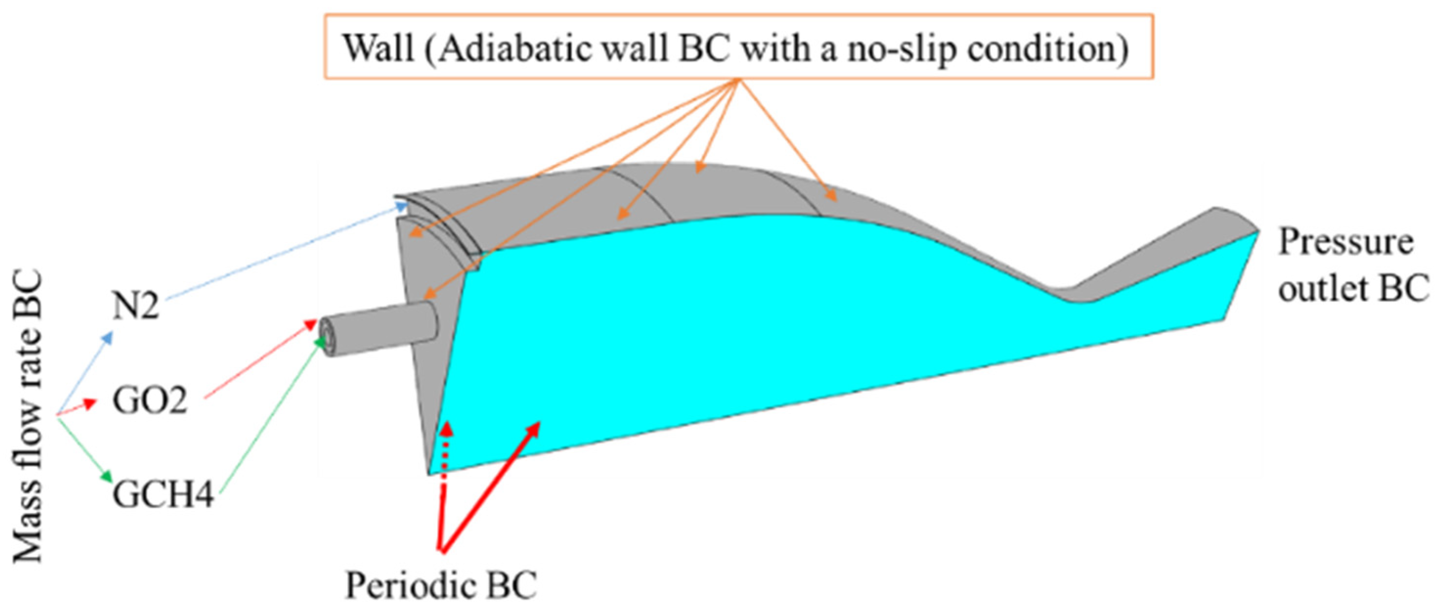
To investigate nitrogen film cooling, the SR5 simulation was conducted using the boundary conditions listed in
Table 3. The wall temperature contour of the SR5 simulation is shown in
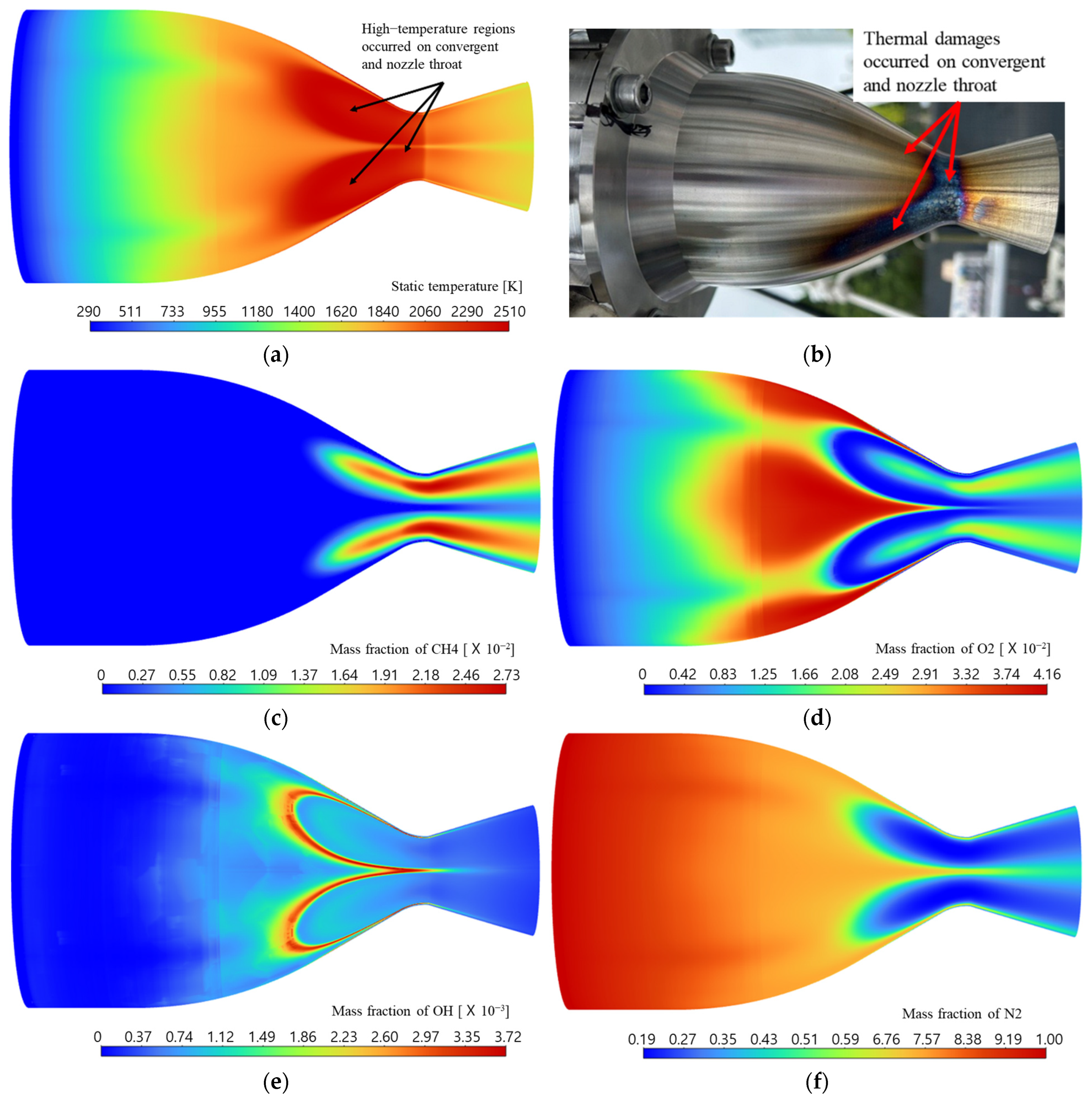
Figure 9a. It can be observed that a high-temperature region occurred in the converging section and throat of the nozzle. The high-temperature region could potentially cause structural damage to the SR5 thrust chamber wall, as visualized in
Figure 9b.
The species mass fraction contours of GCH4, GO2, OH, and N2 are shown in
Figure 9c–f. It is observed that a high mass fraction of GCH4 is distributed on the nozzle wall where high temperature occurs. The presence of GCH4 at the nozzle wall results in a high temperature by combusting with GO2, as observed in
Figure 9c,d.
Figure 9e shows the reaction that occurred on the nozzle wall using the mass fraction of the OH contour. The mass fraction of N2 is low on the throat region of the nozzle wall, at the same location where the mass fractions of GCH4 and GO2 and the wall temperature are high, as observed in
Figure 9f. The presence of higher mass fractions of GCH4 and GO2 compared to that of N2 indicates that GCH4 and GO2 have higher momentum than N2 and touch the convergent and throat sections of the nozzle wall. This can be inferred from the calculated injection velocities of GCH4, GO2, and N2, which are 279, 157, and 133 m/s, respectively. When the number of injectors is not sufficient or the flow area of the injector is not large enough, the injected fuel and oxidizer have a large flow velocity and momentum to satisfy the required mass flow rate. Due to this strong momentum, the injected fuel and oxidizer collide with the nozzle contraction section and a strong combustion reaction occurs in the collision area. This phenomenon prevents the coolant from flowing along the nozzle wall. It can be concluded that the high velocities of GCH4 and GO2 cause inadequate film cooling in the base case of the SR5 simulation, which can be solved by increasing the number of injectors on the face plate. The effect of increasing the number of injectors was investigated and is discussed in future sections regarding the SR and MR configurations.
3.2. Effect of Injectors in SR Configurations
To investigate the effect of the number of injectors on nitrogen film cooling for the thrust chamber wall, the SR5 case and a set of six new injector face plate cases based on the number of injectors (SR8, SR10, SR12, SR16, SR20, SR24) placed circularly at a fixed radial position of R
2 = 15 mm on the injector face plate were considered. The combustion simulations were conducted using the inlet boundary conditions listed in
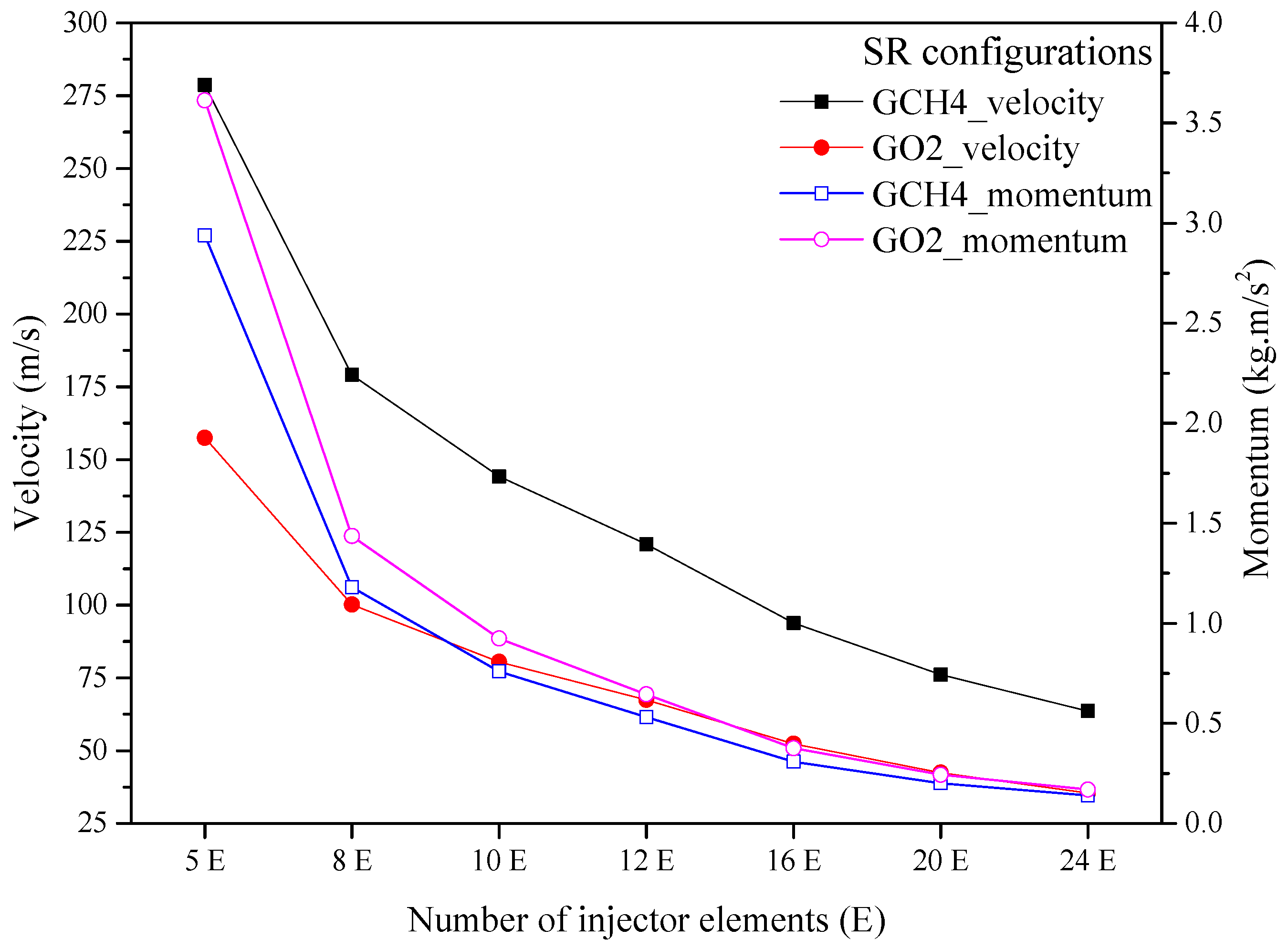
Table 3. As the number of injectors increased, the injector areas for GCH4 and GO2 increased. Thus, the mass flow rate per injector decreased when maintaining the same total mass flow rates. Therefore, the injection velocities of GCH4 and GO2 decreased and the GCH4 and GO2 momentum values using Equation (5) decreased as the number of injectors increased. These trends can be seen in
Figure 10. However, the momentum ratio of GCH4 to GO2 remained the same for all the simulation cases.
The wall temperature and mass fraction of the coolant for the SR configurations are shown in
Figure 11 and
Figure 12, respectively. Because of the decreasing injection velocity,
Figure 11a–d shows the high-temperature hotspot region in the converging section and nozzle throat of the SR5 case decreased significantly with increasing the number of injectors up to the SR12 case. After increasing the number of injectors above the SR12 case, a steady decline in the wall temperature distribution was observed, specifically in the hot region, as shown in
Figure 11e–g. Similarly, the mass fraction of the coolant is distributed unevenly on the nozzle wall at the high-temperature region of the nozzle, as shown in
Figure 12a. Increasing the number of injectors while decreasing injection velocity gradually reduces the high momentum intensity of GCH4 and GO2 on the nozzle wall. Consequently, the very low intensity of the coolant distribution on the nozzle wall in
Figure 12a gradually increases and is eventually evenly distributed after SR12, as shown in
Figure 12d–g. The higher wall temperature ranges of the convergent part of the nozzle near the throat section are shown in
Figure 13. It was observed that the higher wall temperature ranges decreased as the number of injectors increased.
The effect of the number of injectors on the flow structure of the GCH4 and GO2 was visualized using the streamline contours. The streamline paths from the GCH4 and GO2 inlets for the SR configurations are shown in
Figure 14.
Figure 14a shows that the GCH4 and GO2 streamlines flow axially and touch the nozzle wall. This causes thermal damage on the nozzle wall in the SR5 case. In
Figure 14b–g, it is observed that the streamlines from the GCH4 inlet flow axially from case SR5 up to SR12, after which it starts to deflect up towards the chamber wall in case SR24. The GCH4 and GO2 streamlines near the nozzle wall start to detach from the nozzle wall and form a thin gap between the nozzle wall and streamlines. The size of the gap increases gradually with the number of injectors, and the gap allows the coolant to flow near the nozzle wall and forms a thin film to protect it from thermal damage.
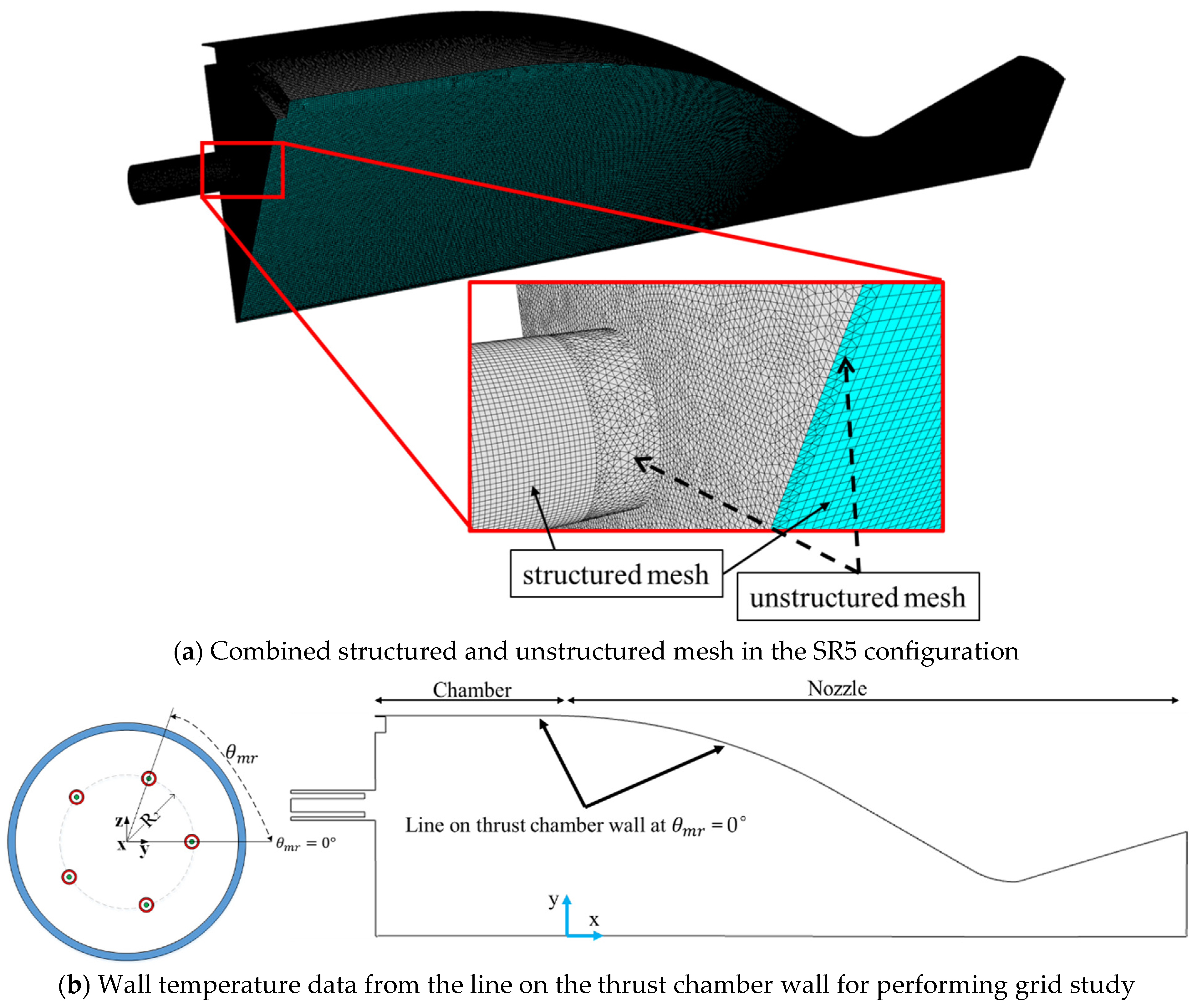
The numerical data of the wall temperature and mass fractions of GCH4, GO2, and coolant were extracted from the axial positions of the chamber and nozzle walls at two different azimuthal angles (θ = 0°, m°). Here, θ = 0° (i.e.,
) indicates an angle that lies on the y-axis in
Figure 7b, and this value is the same for all the simulation cases. In contrast, θ = m° (i.e.,
) indicates an angle from the y-axis to the middle of the injectors, and the value becomes different as
is decreased with an increasing number of injectors for all the simulation cases. Therefore, we refer to this angle as m° for simplification in this paper. The wall temperature profiles at θ = 0° and m° along the axial direction are shown in
Figure 15. The axial chamber position starts from −33 to 0 mm, and the nozzle position starts from 0 to 120 mm. It is observed in
Figure 15a that the wall temperature profiles for the SR5 case gradually started increasing from x = −33 mm to x = 55 mm, where it reached the maximum value. Beyond x = 55 mm, the wall temperature profile decreased. A similar profile trend for the SR8 case is observed, but the location of the maximum wall temperature is at x = 65 mm. For SR10, SR12, SR16, SR20, and SR24, the locations of the maximum wall temperature are approximately at x = 86 mm (nozzle throat). This reveals that the maximum wall temperature locations for the SR5 and SR8 cases occurred before the nozzle throat, whereas they occurred after the nozzle throat for the remaining SR10, SR12, SR16, SR20, and SR24 cases. The overall wall temperature profile and maximum wall temperature decrease as the number of injectors increases, as shown in
Figure 15a.
Figure 15b shows the wall temperature profile at θ = m°, where the maximum wall temperature occurs at x = 86 mm (the nozzle throat). The temperature profiles for the SR12, SR16, SR20, and SR24 cases at θ = 0° and m° are similar, indicating a uniform temperature distribution, as shown in
Figure 11.
The mass fractions of the GCH4, GO2, and OH distributions along the axial direction of the wall at θ = 0° and m° are shown in
Figure 16. In
Figure 16a, the mass fraction of GCH4 starts to increase from zero at x = 50 mm for the SR5 case and at x = 60 mm for the SR8 case. In contrast, the increase begins after x = 85 mm for SR10, SR12, SR16, SR20, and SR24. In
Figure 16b, the mass fraction of GCH4 starts to increase after x = 85 mm for all the simulation cases. The GCH4 on the wall reacts with GO2, initiating combustion and increasing the wall temperature, as shown in
Figure 15. The mass fractions of the GO2 distributions along the axial direction of the wall at θ = 0° and m° are shown in
Figure 16c,d. To illustrate the combustion reaction on the wall, the mass fraction of OH distribution along the axial direction of the wall is shown in
Figure 16e,f. Notably, the OH peak correlates with the maximum wall temperature in each simulation case. Moreover, the OH peak shifts downstream of the nozzle as the number of injectors increases.
The distribution of the coolant mass fraction is shown in
Figure 17. In the SR5 case, the coolant profile is decreased significantly along the axial direction of x = 45 mm at θ = 0°. This decrease indicates inadequate cooling along the nozzle wall, which causes damage to the high-temperature region where the nozzle wall is damaged, as shown in
Figure 9. This damage results from the thermal stress induced by hot gases. However, the cooling deficiency is mitigated by reducing the flow momentum, which is achieved by increasing the number of injectors, as shown in
Figure 17a. The investigation of the SR configurations shows a reduction in the wall temperature of the nozzle and addresses the damage concerns. However, the wall temperature of the injector face plate remains considerably high, as shown in
Figure 11h. This issue can potentially be resolved by employing multiple rows with multiple injectors, which is a solution discussed in the following MR configuration section.
3.3. Effect of Injectors in MR Configurations
To investigate the effect of the number of injectors in multiple rows on nitrogen film cooling for the thrust chamber wall, a set of six new injector plates based on the number of injectors (MR24, MR30, MR36, MR48, MR60, and MR72) placed on the injector face plate circularly at three fixed radial distances of R
1 = 10 mm, R
2 = 15 mm, and R
3 = 25 mm were considered. Combustion simulations were conducted using the inlet boundary conditions listed in
Table 3. As the number of injectors increased, the injector areas for GCH4 and GO2 increased. Thus, the mass flow rate per injector decreased when maintaining the same total mass flow rates. Therefore, the injection velocities of GCH4 and GO2 decreased and the respective momentum using Equation (5) also decreased with an increasing number of injectors, as shown in
Figure 18.
The wall temperatures and mass fractions of the coolant from the MR configuration simulations are shown in
Figure 19 and
Figure 20, respectively. As a result of decreasing the injection velocity, a significant low-temperature region occurs in the chamber wall and the wall temperature of the nozzle becomes uniform in the MR48 case, as shown in
Figure 19a–d. After the MR48 case, a non-uniform temperature distribution is observed for the MR60 and MR72 cases, as shown in
Figure 19e,f. The non-uniform temperature distribution is due to the 30 and 36 injectors located at R
3 = 25 mm for the MR60 and MR72 cases, respectively. A similar trend is observed for the coolant mass fraction distribution, as shown in
Figure 20. The injector face plate temperatures for all the cases are shown in
Figure 21. The MR24 face plate case has a very high temperature compared to the other cases. Increasing the number of injectors reduces the high temperature of the face plate to a lower value, as in the MR72 case. The high temperature in the MR24 case is due to the larger space between the injectors, whereas the low temperature in the MR72 case is due to the smaller space between the injectors. Visualizing the temperature contours in
Figure 19 and
Figure 21 shows that the MR48 case can be an optimistic design.
The effect of the number of injectors on the flow structure of the GCH4 and GO2 was visualized using the streamline contours. The streamlines from the GCH4 and GO2 inlets, particularly those located at R
3 = 25 mm and θ = 0°, for the MR configurations are shown in
Figure 22. A significant difference in the flow observed is that the GCH4 streamlines start slightly deflecting towards the chamber wall as the number of injectors increased. Consequently, the gap between the streamlines and the chamber wall gradually decreased. Similarly, it is observed that the GO2 streamlines gradually touched the chamber wall as the number of injectors increased. This is due to the decreased space between the injectors at R
3. Consequently, it causes the coolant distribution to become uneven, as shown in
Figure 20e,f.
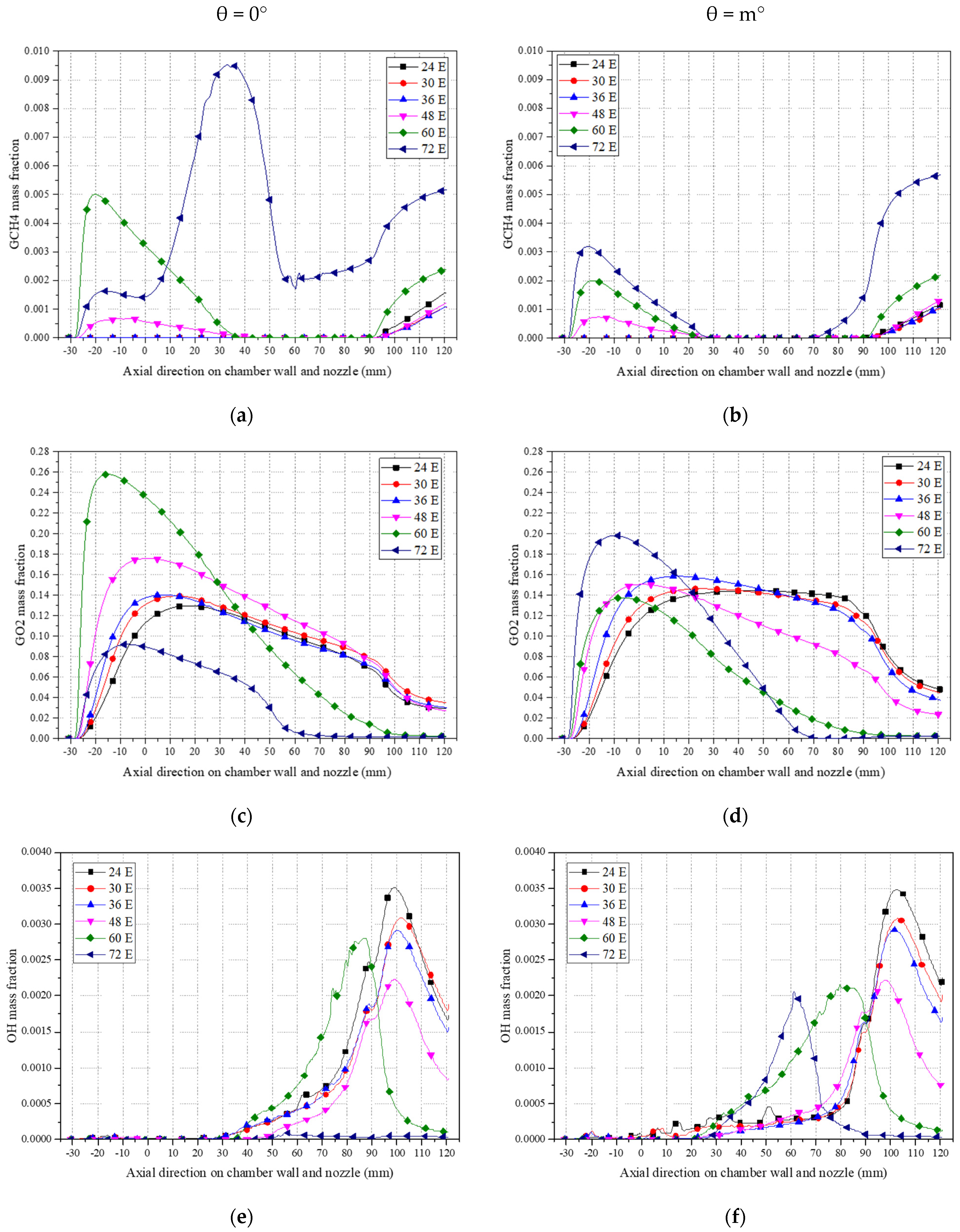
The wall temperatures and mass fractions of GCH4, GO2, OH, and coolant at two different azimuthal angles (θ = 0° and m°) for the MR configurations are shown in
Figure 23,
Figure 24 and
Figure 25. In the MR configurations, θ = m° (i.e.,
). In
Figure 23, the maximum wall temperatures for all the cases except MR60 and MR72 occurred near the nozzle throat, whereas they occurred before the nozzle throat at the azimuthal angle of θ = m° for the MR60 and MR72 cases. The axial wall temperature profile decreases with the number of injectors from the MR24 case to the MR48 case. However, after increasing the number of injectors in the MR60 and MR72 cases, the axial wall temperature profile from x = 20 mm increases compared to the other cases. The wall temperature increases in the MR60 and MR72 cases are due to the mass fraction of GCH4 reacting with GO2, as shown in
Figure 24a–d. The mass fraction of OH in
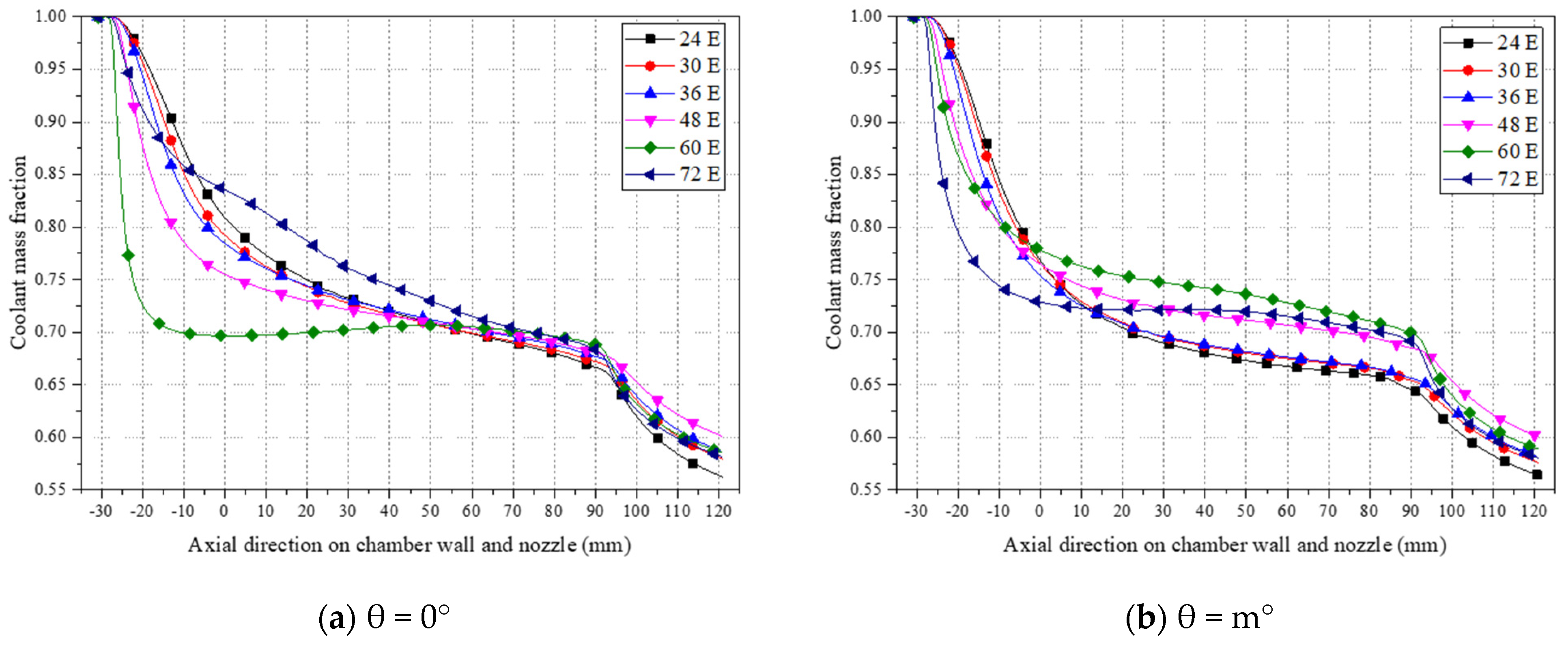
Figure 24e,f shows that the peak OH value is obtained after the nozzle throat for all the cases except MR60 and MR72. The peak OH value obtained in the MR48 case is lower than that in the other cases, indicating that the reaction rate is low, which results in a low wall temperature. The coolant mass fractions are compared in
Figure 25, which shows that the coolant wall profiles for all the cases are reasonably good up to an axial position of 90 mm and the coolant mass fraction is above 0.65. After 90 mm, a coolant profile is obtained below a mass fraction of 0.65. Overall, the coolant profile throughout the chamber and nozzle walls (mainly after 90 mm) for the MR48 case is better than that of the other cases, as shown in
Figure 25.
3.4. Performance Analysis
For the cooling performance analysis, the adiabatic cooling effectiveness (
) for all the simulations in the SR and MR configurations is calculated using Equation (6), and the performance comparison is shown in
Figure 26 and
Figure 27. For the SR configuration in
Figure 26, the
profile at the two angles on the nozzle wall is improved as the number of injectors is increased. The SR5 case has a poor
on the nozzle wall, which causes the high wall temperature observed in
Figure 11a. The poor
profile is improved as the number of injectors is increased in the SR24 case. Overall, the
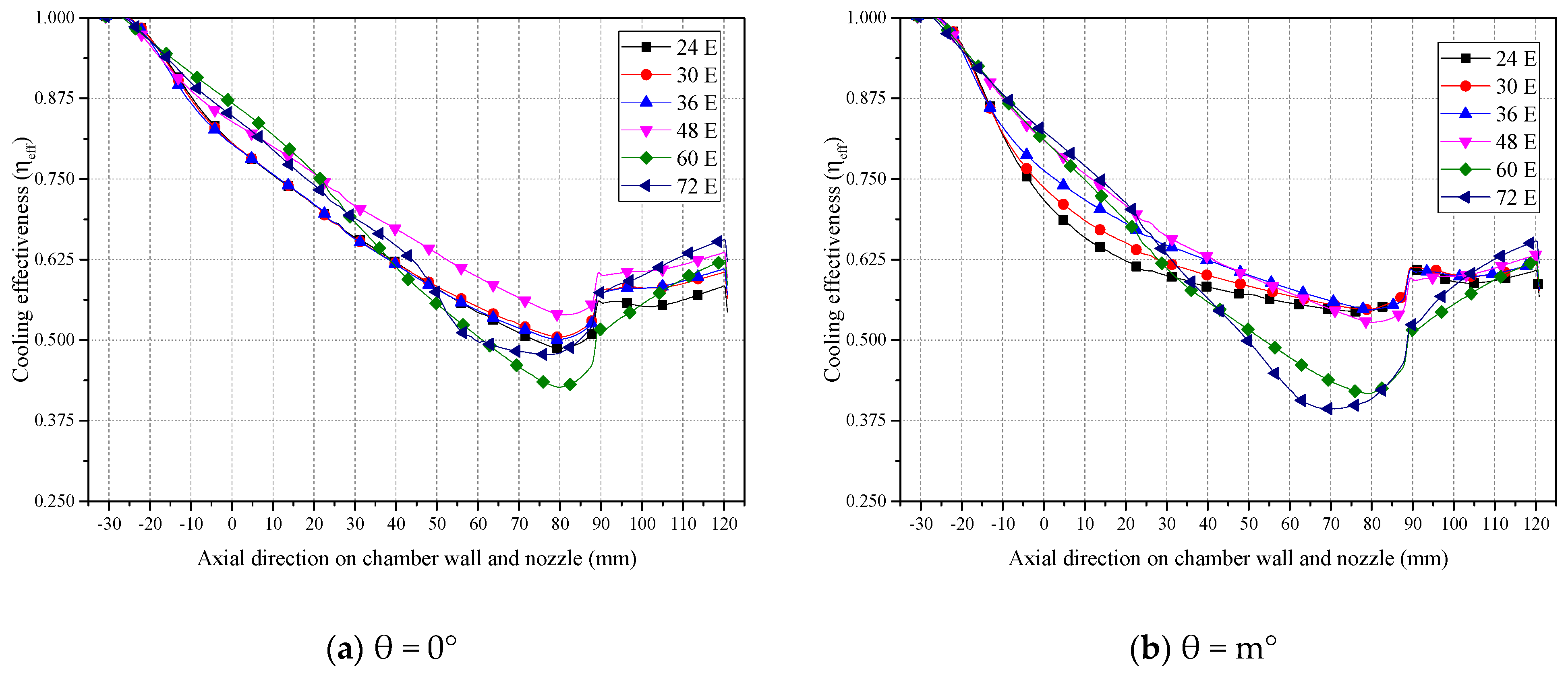
profile is enhanced by the reduction in the injection velocities of GCH4 and GO2. For the MR configurations in
Figure 27, the
profile on the nozzle wall significantly increases up to the MR48 case. Subsequently, it decreases as the number of injectors is increased to approximately 60 and 72 in the MR60 and MR72 cases, respectively. Additionally, when comparing the cooling effectiveness for the same number of 24 injectors in both the SR24 and MR24 cases in
Figure 28, the MR24 case shows superior cooling effectiveness compared with SR24, except on the nozzle wall from 50 to 90 mm, where SR24 performs slightly better than MR24. Furthermore, in comparisons with the MR48 case, overall, the MR48 case shows a better cooling effectiveness profile than the other simulation cases.
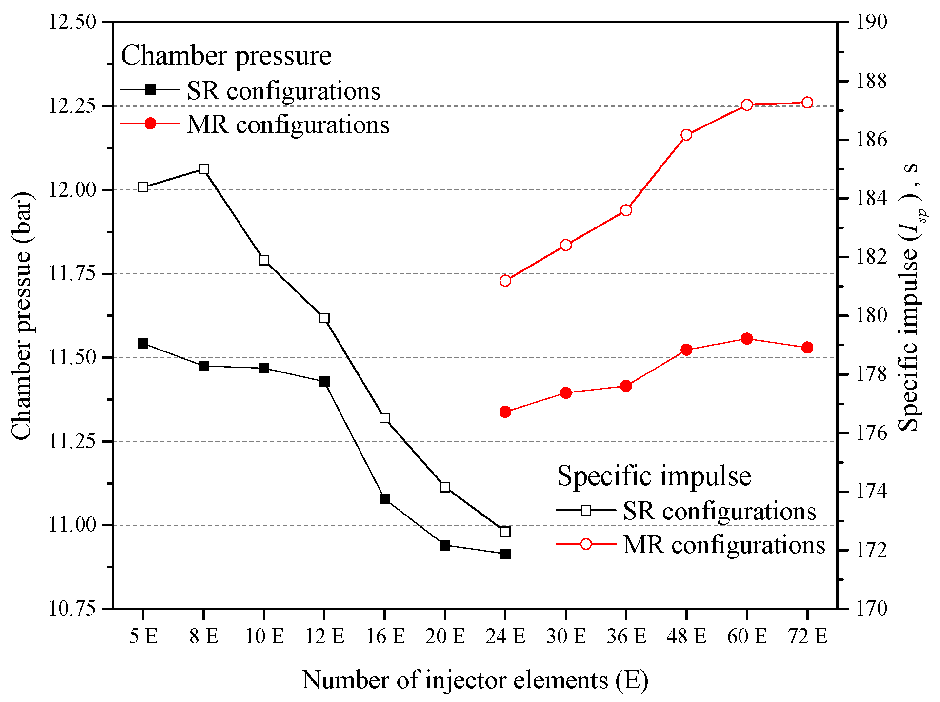
To analyze the combustion performance, the specific impulse (
) for all SR and MR configurations was calculated using Equation (7). The measured chamber pressure and theoretical specific impulse were 12.05 bar and 203.5 s, respectively. In the base case configuration, the specific impulse was 210.48 s for SR5 without nitrogen injection, and it decreased to 184.38 s when nitrogen injection was considered. This resulted in a specific impulse loss of 12.4% when the nitrogen injection was considered. The combustion performance comparison is shown in
Figure 29. In the SR configurations, the chamber pressure and specific impulse decrease with the number of injectors. Interestingly, the SR24 case shows a low chamber pressure and specific impulse, whereas the MR24 case shows a high chamber pressure and specific impulse, even though both configurations have the same number of injectors. The low chamber pressure and specific impulse in the SR24 case stem from the narrow spacing between injectors. This limitation impedes proper propellant mixing, ultimately diminishing combustion performance. In contrast, the high chamber pressure and specific impulse observed in the MR24 case are attributed to placing the same number of injectors in multiple rows on the injector face plate, as presented in
Figure 4a. This configuration allows for greater spacing between the injectors than in the SR24 case, facilitating thorough propellant mixing and superior combustion performance. In the MR configurations, the chamber pressure is increased up to MR60 and is slightly decreased in MR72. The specific impulse increases with the increasing number of injectors. However, the calculated specific impulse for all the simulations is lower than the theoretical specific impulse. Comparing the MR48 case with the SR5 case, the MR48 case achieves almost the same chamber pressure as the base case SR5 and a higher specific impulse than the base case SR5. Overall, the performance of the MR configuration surpasses that of the SR configuration due to an increased spacing between the injectors. This enhanced spacing facilitates better mixing, leading to more efficient combustion, higher chamber pressure, and an improved specific impulse. In MR configurations, cases with fewer than 48 injectors show a low chamber pressure and specific impulse and a high wall temperature on the face plate, attributable to excessively wide spacing between the injectors. Conversely, cases with more than 48 injectors show a high chamber pressure and specific impulse and an elevated wall temperature on the nozzle wall due to narrower injector spacing. Ultimately, the present work concludes that the MR48 configuration is the optimal choice to mitigate thermal damage based on a comparative analysis of the injector face plate and nozzle wall temperatures and combustion performances.


