Article

Dynamic Binary-Medium Model for Jointed Rock Subjected to Cyclic Loading

1
School of Civil Engineering and Architecture, East China Jiaotong University, Nanchang 330013, China
2
College of Water Resources & Hydropower, Sichuan University, Chengdu 610065, China
3
College of Water Conservancy & Architectural Engineering, Shihezi University, Shihezi 832003, China
*
Author to whom correspondence should be addressed.
Mathematics 2024, 12(11), 1765; https://doi.org/10.3390/math12111765
Submission received: 15 May 2024 / Revised: 31 May 2024 / Accepted: 2 June 2024 / Published: 6 June 2024
(This article belongs to the Special Issue Numerical Modeling and Simulation in Geomechanics)

Abstract

:
Revealing the damage mechanism of jointed rocks under a cyclic loading and formulating the corresponding dynamic constitutive model to meet the requirements for the evaluation of anti-vibration safety for critical engineering construction and operation is an essential, urgent and basic subject. Based on the breakage mechanics for geological material, jointed rock is considered as a binary-medium material composed of the bonded elements and frictional elements. The bonded elements are regarded as elastic-brittle elements, and the frictional elements are regarded as elastic-plastic elements. Firstly, the static binary-medium model for jointed rock is established based on the homogenization method and by introducing the breakage ratio and the strain concentration coefficient. Then, the dynamic binary-medium model for jointed rock under cyclic loads is established considering the nonlinear damage effect resulting from cyclic loads. The breakage ratio formula is improved, and the Drucker–Prager criterion is introduced. During the unloading stage, it is supposed that the breakage ratios and strain concentration coefficients remain unchanged and the stress–strain ratios of both bonded elements and frictional elements are constant. The model is verified by static and dynamic triaxial tests of jointed rock samples with an interpenetrated joint. It is found that the model can describe the nonlinear stress–strain characteristics of a jointed rock subjected to cyclic loads relatively well and can reflect the effects of cyclic loading on the deformation and damage, including the lateral deformation characteristics. Meanwhile, the typical three-stage (varying from sparse to dense to sparse) evolution laws of the stress–strain curves are also reflected relatively well.

1. Introduction

With the rapid development of computing techniques, it becomes possible to utilize complex geotechnical constitutive models. Constitutive equations of boundary value problems in rock engineering depend on the mechanical property of rock material, such as nonlinearity, heterogeneity, anisotropy and discontinuity. Thus, the study of constitutive relations is one of the focuses and difficulties in rock mechanics and its application. The Sichuan–Tibet railway from Ya’an to Nyingchi, which has been launched, will be confronted with the risk of high-intensity earthquake disasters. Rock masses in the railway tunnel and subgrade are subjected to the cyclic loading from trains. In addition to the seismic cyclic loads [1] and the cyclic traffic loads [2,3] of high-speed trains and automobiles, construction loads, loads on the bedrock of generating sets in hydroelectric power stations, loads on the pile foundation of a large wind turbine and wave loads on coastal embankments all constitute cyclic loads. Obviously, in order to meet the requirements for the evaluation of anti-vibration safety for critical engineering construction and operation, a study establishing a dynamic constitutive model for jointed rock subjected to cyclic loading is of great economic and social importance.
The dynamic constitutive model of rocks subjected to impact loads at different strain rates has been thoroughly studied considering the loading rate effect by researchers like Taylor et al. [4], Chen et al. [5], Song et al. [6], Shu et al. [7], Lee et al. [8] and Wang et al. [9]. The viscoelastic theory or the damage mechanics theory is adopted, and many achievements have been made. Compared with the blasting impact loads at different strain rates, the most notable feature of the cyclic loads is the repeatability of loading and unloading. Rocks under cyclic loading, which can cause damage when the applied stress is lower than static strength, exhibit Masing behavior and the ratcheting effect. The deformation and strength characteristics change continually as the number of cycles increases [10]. Research on cyclic dynamic constitutive models of rock masses has been conducted by some experts to a certain degree. Based on cyclic direct shear tests of jointed rocks, focused on the joint surface roughness degradation, dilatancy and shear stress–displacement relation, the damage and shear stress–displacement constitutive models are developed by applying nonassociated plasticity, law of thermodynamics, damage theory, etc. [11,12,13,14,15,16]. To a certain extent, these models can predict the cyclic shear behavior of regularly shaped joints. Aimed at describing the damage mechanical properties of jointed rocks subjected to cyclic uniaxial or triaxial loading, a series of damage cumulative models are proposed based on the axial irreversible deformation, statistical damage mechanics, continuum damage mechanics or the Manson–Coffin formula [17,18,19,20,21,22]; these models considered the effects of axial irreversible deformation, loading frequency and amplitude or micro-flaws, etc., which are effective for predicting the cumulative fatigue damage of jointed rock to a certain extent. While, the stress–strain models of joint rocks subjected to cyclic uniaxial or triaxial loading are relatively few [23,24,25,26,27], in these models, the irreversible thermodynamics theory and endochronic theory, elastoplastic cellular automata, theory of plasticity, the subloading surface theory or the modified cohesion weakening and frictional strengthening model are used. The unloading–loading process in the pre-peak or post-peak region is simulated, and the inherent anisotropy, hardening behavior, viscosity and isotropic softening are considered. These modeled stress–strain curves partially agreed with the experimental ones. In short, these models mainly describe the stress–strain relations of prefabricated intermittent joints in cyclically triaxial and uniaxial tests or penetrating joints in cyclically direct shear tests, and the Masing behavior and ratcheting effect are not simulated very well.
In general, the studies on the dynamic constitutive model of penetrating jointed rocks under cyclically triaxial and uniaxial loading are relatively few; most are based on the phenomenological perspective, and analyses from the mesoscopic and microscopic perspective based on the physical–mechanical mechanism are few as are the elasto-plastic dynamic constitutions based on elasto-plastic theory. If the phenomenological method and the physical–mechanical mechanism are combined, the microscopic characteristics and the physical–mechanical mechanism can be revealed, and the macroscopic strength and deformation characteristics can also be considered. There is no doubt that the constitutive model will describe the mechanical properties of the rock more accurately and thoroughly. To study the dynamic constitutive model of jointed rock under cyclic loads in more depth, the cyclic and dynamic constitutive model for jointed rock considering the effects of cyclic loading and unloading is built based on the binary-medium model of geotechnical material and within the framework of rock and soil breakage mechanics. After that, the model will be validated by the static and dynamic cyclic triaxial tests of jointed rock, to obtain a constitutive model that can reveal the stress–strain property of jointed rock subjected to cyclic loading.

2. Binary-Medium Model

Rock and natural soil belong to structural geomaterials; their brittleness is associated with the cementation between particles. The structural property is reflected in the ordered variation of strong and weak cementation. Bonded blocks, namely, bonded elements, are formed where the adhesion is strong; their shearing strength is mainly reflected in the cohesion part. While weakened bands, namely, frictional elements, are formed where the bonding is weak, and their shearing strength is primarily reflected in the internal friction part. Besides the apparent cohesion resulting from intergranular occlusion, the cohesion essentially results from intergranular cementation. The cohesion reaches a peak value when the deformation is not large, showing a brittle property. In contrast, the frictional force comes into play fully only when the deformation is large enough, showing a plastic property. Both the bonded blocks and the weakened bands bear external loads. The bonded blocks with the brittleness gradually fracture and transform to become weakened bands with a frictional property, as shown in Figure 1. The reduced bearing capacity resulting from the fractured bonded blocks is compensated for in part or in whole by the weakened bands; thus, the structural rock and soil exhibit strain-softening or strain-hardening characteristics. Based on these understandings, Shen et al. [28] conceptualized structural rock and soil material as binary mediums composed of bonded blocks and weakened bands, which jointly share the load and resist deformation.
A simplified element combination of binary-medium material is shown in Figure 2. The bonded elements and the frictional elements jointly bear external loads and resist deformation. The elements are composed of the spring, slider and bonded bar, which represent elasticity, plasticity and brittleness, respectively. The bonded elements are assumed to be elastic-brittle and simplified as a combination of spring elements and bonded bar elements. The frictional elements are assumed to be elastic-plastic and simplified as a combination of spring elements and slide elements. Geomaterials damage gradually, so the bonded elements also damage gradually. Each damaged bonded element will transform into a frictional element. As shown in Figure 3, the load will be reduced to a specific value, and the bearing capacity will be compensated for by the frictional elements. The compensatory path is divided into two types: type (1) represents that the strength of frictional elements is higher than that of bonded elements, and in this case, strain hardening occurs in the materials; type (2) represents that the strength of frictional elements is lower than that of bonded elements, and strain softening occurs in this case. The frictional elements converted from the bonded elements may exhibit plastic flow, and the strengths remain constant, which is situation (a) shown in Figure 3. Also, it may be the softening of frictional elements or further breakage of bonded elements, which belongs to situation (b) shown in Figure 3.
Liu et al. [29,30] conducted stress path test studies on different structural bodies with two different arrangements. They found that structural bodies damage progressively and transform into weakened bands during the loading process. The weakened bands and structural bodies jointly share loads, and the structural bodies exhibit strain-softening or strain-hardening characteristics depending on the load sharing ratio. In this study, a breakage classification of structural geomaterial is proposed, as shown in Figure 1. Figure 1a–c represent three kinds of damage situations: not damaged, partially damaged and completely damaged. Figure 1d represents that breakages occur throughout the volume range at failure, and many bonded elements are damaged, namely, volumetric damage. Figure 1f represents that breakages occur mainly near a particular surface, namely, areal damage. Figure 1e represents both volumetric damage and areal damage: although breakages occur throughout the volume range, bonded elements damage intensely mainly along the shear band, while they damage less intensely elsewhere. For soft rocks, the damage mode tends to be as in Figure 1e, and for hard rocks, the damage mode tends to be Figure 1f.
Binary-medium material belongs to a heterogeneous material, as shown in Figure 1. General theories treat heterogeneous materials as a single medium without considering the different properties of the various internal media. While binary-medium theory considers the different interior properties of the frictional elements and the bonded elements, respectively; then, the homogenization theory is used to relate the frictional elements and bonded elements, and the constitutive model is constructed.
The deformation of geomaterial is not uniformly distributed in the whole sample, and the localized deformation effect is pronounced (such as the cases shown in Figure 1e,f). Especially for rock, its failure mode is usually splitting failure or shear failure, and the failure of the bonded elements mainly occurs along a particular surface. In order to better reflect the localized deformation effect of geomaterial and the failure characteristics, the volume and area of the representative volume element (RVE) are divided into the bonded element part and the frictional element part. Then, the stress and strain, which are divided into spherical and deviatoric components, are defined by volume and area weighted average, respectively. The breakage ratio is defined as the volume or area proportion of frictional elements to the RVE, so the breakage ratios are divided into a volume breakage ratio μ v and an area breakage ratio μ s .
The relationships between the global average stress and the local average stress and between the global average strain and the local average strain are obtained according to the homogenization theory:
σ ¯ m = ( 1 μ v ) σ ¯ m c + μ v σ ¯ m f
ε ¯ v = ( 1 μ v ) ε ¯ v c + μ v ε ¯ v f
σ ¯ s = ( 1 μ s ) σ ¯ s c + μ s σ ¯ s f
ε ¯ s = ( 1 μ s ) ε ¯ s c + μ s ε ¯ s f
where σ ¯ m , σ ¯ m c and σ ¯ m f represent the global average normal stress of the RVE, the local average normal stress of the bonded elements and the frictional elements, respectively; σ ¯ s , σ ¯ s c and σ ¯ m f represent the global average shear stress of the RVE, the local average shear stress of the bonded elements and the frictional elements, respectively; ε ¯ v , ε ¯ v c and ε ¯ v f represent average the volumetric strain of the RVE, the bonded elements and the frictional elements, respectively; ε ¯ s , ε ¯ s c and ε ¯ s f represent the average shear strain of the RVE, the bonded elements and the frictional elements, respectively; σ ¯ m = 1 3 σ k k , σ ¯ s = ( 3 2 s i j s j i ) 1 2 , ε v = ε k k , ε s = ( 2 3 e i j e i j ) 1 2 , here s i j = σ i j 1 3 σ k k δ i j , e i j = ε i j 1 3 ε k k δ i j , and Kronecker delta δ i j = 0 i j 1 i = j .
Then, we begin to derive the incremental binary-media stress–strain relationship. The global average stress will be expressed as the formula of the global average strain and the current average strain. In the following derivation, variables with a superscript “N” indicate the current value, and the current value plus the corresponding increment is the value after the increment is complete.
To characterize the internal structure of binary media and express the strain relationship between frictional elements, bonded elements and RVE, the structure parameters are introduced as follows:
ε ¯ v c = z v ε ¯ v ,   ε ¯ s c = z s ε ¯ s
where z v and z s are the volumetric strain concentration coefficient and the shear strain concentration coefficient of bonded elements, respectively.
The differentiation of Equation (10) can be obtained as follows:
d ε ¯ v c = H v d ε ¯ v ,   d ε ¯ s c = H s d ε ¯ s
where H v = z v N + z v ε ¯ v ε ¯ v N , H s = z s N + z s ε ¯ s ε ¯ s N .
The constitutive relation of bonded elements is hypothesized as follows:
d σ ¯ m c = C m v d ε ¯ v c + C m s d ε ¯ s c
d σ ¯ s c = C s v d ε ¯ v c + C s s d ε ¯ s c
The constitutive relation of frictional elements is hypothesized as follows:
d σ ¯ m f = F m v d ε ¯ v f + F m s d ε ¯ s f
d σ ¯ s f = F s v d ε ¯ v f + F s s d ε ¯ s f
where C m v , C m s , C s v , C s s and F m v , F m s , F s v , F s s are the material parameters of the bonded elements and the frictional elements, respectively.
According to Equations (1)–(10), we can derive the incremental binary-medium stress–strain relationship. The global average stress increment and the global average strain increment are expressed as the formula of the global average volumetric strain increments, the global average shear strain increment and the current stresses of the RVE and the bonded elements. The equations are shown as follows:
d σ ¯ m = [ ( 1 μ v N ) C m v H v + F m v F m v ( 1 μ v N ) H v ] d ε ¯ v     + [ ( 1 μ v N ) C m s H s + μ v N μ s N F m s μ v N μ s N F m s ( 1 μ s N ) H s ] d ε ¯ s     F m v 1 z v N μ v N ε ¯ v N d μ v μ v N ( μ s N ) 2 F m s 1 z s N ε ¯ s N d μ s + d μ v μ v C σ ¯ m N σ ¯ m N c
d σ ¯ s = [ ( 1 μ s N ) C s v H v + μ s N μ v N F s v μ s N μ v N F s v ( 1 μ v N ) H v ] d ε ¯ v     + [ ( 1 μ s N ) C s s H s + F s s F s s ( 1 μ s N ) H s ] d ε ¯ s     μ s N ( 1 z v N ) ( μ v N ) 2 F s v ε ¯ v N d μ v 1 z s N μ s N F s s ε ¯ s N d μ s + σ ¯ s N σ ¯ s N c μ s N d μ s

3. Static Binary-Medium Model for Jointed Rock

3.1. Constitutive Relation of Bonded Elements

It is assumed that the breakage of the bonded elements is elastic-brittle. The stress–strain relationship is described by Hooke’s law. When the stress state satisfies the breakage criteria, the bonded elements are damaged. The ideal elastic-brittle model of bonded elements is expressed by the following formula:
d σ ¯ m c = K c d ε ¯ v c
d σ ¯ s c = 3 G c d ε ¯ s c
where K c and G c represent the bulk modulus and the shear modulus of the bonded elements, respectively; they are measured in samples that have not been damaged when they are initially loaded. For jointed rocks, K c and G c can be obtained by the linear elastic stage in stress–strain curves of the complete rock sample.

3.2. Constitutive Relation of Frictional Elements

The frictional elements are transformed from the damaged bonded elements, and their bonding strength all disappears. The deformations of these frictional elements are mainly slippages, exhibiting significant plastic properties. The stress–strain properties are described by the ideal elastoplastic model, in which the stress–strain relationship before yielding is described by Hooke’s law. After yielding, it is described by the plastic model with the Mohr–Coulomb yield criterion:
F f = σ 1 σ 3 2 σ 1 + σ 3 2 sin φ c cos φ = 0
The material parameters of the frictional elements include elastic modulus, Poisson’s ratio, cohesion and internal friction angle. They can be obtained according to the stress–strain characteristics of rock samples in the residual state (or stable state). For the strain-hardening type, the material parameters of the frictional elements are determined according to the stress–strain relationship in the steady state, while for the strain-softening type, they are determined according to the stress–strain relationship in the residual state.

3.3. Evolution Laws of Breakage Ratio

With an increase in the stress and strain levels, the bonded elements are continuously damaged and transformed into frictional elements. Consequently, the breakage ratio increases constantly until the sample fails. From the microscopic point of view, the change in the breakage ratio is closely related to the failure of cementation between the particles and the initiation, propagation and closure of microcracks during the loading process. In this process, the bonded elements in rocks are gradually transformed into frictional elements, and the breakage ratio increases from 0 at the initial stage to 1 at failure without considering the initial damage. Here, the strain level is used to describe the evolution law of the breakage ratio.
The evolution rules of the volume breakage ratios and the area breakage ratios are described as follows:
μ v = 1 e p v ε ¯ v q v
μ s = 1 ( 1 + r s ε ¯ s ) e p s ε ¯ s q s
where p v , q v , r s , p s and q s are the model parameters. When there are volume expansions during the deformation process, the volume breakage ratios after expansion take the values at the beginning of the volume expansion. Because the samples generate breakage bands, the influence of dilatancy can be described by the area breakage ratios. Figure 4a–c show the evolution law of breakage ratios obtained from the above formula and the influence of model parameters. It is found that the volume breakage ratios and the area breakage ratios all change from 0 at the initial state to 1 at failure gradually, and different model parameters can represent different evolution rules.

3.4. Evolution Laws of Strain Concentration Coefficients

The strain concentration coefficients represent the relationship between the strain of the bonded elements and the strain of the representative elements. The evolution laws of the strain concentration coefficients are closely related to the breakage ratios; they can be described by the following equations:
z v = 1 t v μ v
z s = 1 t s μ s
where t v and t s are model parameters that can be obtained through curve fitting.

4. Dynamic Binary-Medium Model for Jointed Rock Subjected to Cyclic Loading

4.1. Stress–Strain Relationship at the Monotone Loading Stage

The yield criterion of the frictional elements and the evolution formula of the area breakage ratio are the main differences between the stress–strain relationship at the monotone loading stage and in the static binary-medium model.
The adopted yield criterion of frictional elements is the Drucker–Prager criterion:
F f = J 2 f α I 1 f k = 0
where J 2 f is the second invariant of the deviatoric stress of the frictional elements, I 1 f is the first invariant of the stress of the frictional elements. α and k are the strength parameters of the frictional elements, which are related to the cohesion c and the internal friction angle φ : α = sin φ 3 ( 3 + sin 2 φ ) , k = 3 c cos φ ( 3 + sin 2 φ ) .
The evolution laws of the area breakage ratio μ s can be described by the following equation:
μ s = 1 e p s ε ¯ s q s

4.2. Stress–Strain Relationship at the Unloading Stage

Suppose the breakage ratios and structural parameters (namely, the strain concentration coefficients) remain unchanged during unloading, and the stress–strain ratios of both bonded elements and frictional elements are constant. Then, Equations (11) and (12) can be simplified into the following equations:
d σ ¯ m = [ ( 1 μ v N ) C m v z v N + F m v F m v ( 1 μ v N ) z v N ] d ε ¯ v     + [ ( 1 μ v N ) C m s z s N + μ v N μ s N F m s μ v N μ s N F m s ( 1 μ s N ) z s N ] d ε ¯ s
d σ ¯ s = [ ( 1 μ s N ) C s v z v N + μ s N μ v N F s v μ s N μ v N F s v ( 1 μ v N ) z v N ] d ε ¯ v     + [ ( 1 μ s N ) C s s z s N + F s s F s s ( 1 μ s N ) z s N ] d ε ¯ s
where the breakage ratios μ v N and μ s N , the strain concentration coefficients z v N and z s N take the values at the beginning of each unloading stage. The parameters of the bonded element material are determined according to the beginning state at the unloading stage, while the parameters of the frictional element material are determined according to the ending state at the unloading stage.

4.3. Stress–Strain Relationship at the Cyclic Loading Stage

During the loading process after the monotone loading stage, the breakage ratios and strain concentration coefficients are supposed to be unchanged until the maximum historical axial strain is reached. In this case, the stress–strain relationship is the same as that under unloading, namely, Equations (22) and (23). After the maximum historical strain is reached, the stress–strain relationship is described as same as that at the monotone loading stage. The shear and volume moduli of the bonded element material are determined according to the stress–strain curves during initial loading and during loading at the cyclic stage. Meanwhile, the parameters of the frictional element material are determined according to the stress–strain curve of rock samples at the steady state for strain-hardening behavior or at the residual state for strain-softening behavior.

5. Experimental Verification of Static and Dynamic Binary-Medium Model

5.1. Experiment Method

Intact samples and samples with joint dip angles of 30° were prepared using cement, sand and water with a mass ratio of 1:15:1.6 [31]. The cement was the complex Portland cement (P.C 32.5R), and the river sand had a particle size distribution ranging from 0.1 mm to 0.5 mm. The density was 2.1 g/cm3, and the uniaxial compressive strength of the intact sample was 650 kPa. Figure 5 shows the mold and the prepared sample of ϕ50 mm × 100 mm with a 30° dip angle. Here, the broken line indicates the joint plane, which is a contact surface of the two parts of the matrix, and no material was filled in it. The joint surface is almost a flat plane when the effect of sand size is neglected. The steps for preparing the jointed rock sample are as follows: (I) the sample was compacted in the mold for four layers; (II) the bolts were removed, and then, the rock matrix was sheared into two parts by hand along the precast plane in the mold, which had a certain dip angle; (III) the two fracture surfaces were leveled up by the aforementioned mixtures, and then, the two parts of the mold containing the sample were connected again with bolts; (IV) the sample within the mold was saturated by vacuum pumping and then placed in water indoors for 7 days; and (V) the sample was removed from the mold and an artificial jointed rock sample containing a penetrating joint for the standard triaxial apparatus was obtained.
The tests were conducted using a GCTS dynamic triaxial apparatus as shown in Figure 5. An LVDT was installed to measure the radial strain. Firstly, the static triaxial tests under the confining pressures of 100 kPa, 200 kPa, 300 kPa and 400 kPa were completed with an axial strain rate of 0.15%/min. When the axial strain reached 15%, the test stopped. Then, cyclic triaxial compression tests of the jointed rock sample with a 30° dip angle were conducted under the confining pressure of 200 kPa. After the confining pressure was applied, the deviatoric stress was first applied with an axial strain rate of 0.15%/min until it reached the designed maximum stress of 1600 kPa. Then, the cyclic load was applied with a given frequency of 1.0 Hz and a sinusoidal waveform. The maximum deviatoric stress was maintained constant at 1600 kPa, and the minimum deviatoric stress was kept constant at 20 kPa. When the sample failed, the test stopped.

5.2. Verification of Static Triaxial Tests

The RVE was chosen as the object of constitutive model verification instead of a discretized numerical model. Firstly, the static binary-medium model was used to predict the static triaxial tests of jointed rock samples with a 30° dip angle under different confining pressures. The model parameters are shown in Table 1 and Table 2. Here, E c , μ c , E f and μ f are the elastic modulus and Poisson’s ratio of the bonded elements and the frictional elements. The comparisons between the predictions and the experiments of the static stress–strain curves and the volumetric strain curves at different confining pressures are shown in Figure 6, Figure 7, Figure 8 and Figure 9. It was found that the predicted stress–strain curves described the test curves well. They all exhibited strain-softening behavior. And the volumetric strain curves show relatively small volume shrinkage at first and then relatively large volume expansions. As the lateral strain was measured in the middle of samples, the experimental volumetric strain was larger than that of the prediction. Figure 10 shows the prediction of the static stress–strain curves and the volumetric strain curves at different confining pressures. With the confining pressure increasing from 100 kPa to 400 kPa, the deformation modulus, peak strength, residual strength and maximum volume shrinkages all increased gradually, while the volume expansions decreased gradually. Consequently, the static binary-medium model can reflect the stress–strain properties of jointed rock samples under different confining pressures, including the strain-softening behavior, volumetric strain characteristics and the influence rules of confining pressures.

5.3. Verification of Cyclic Triaxial Tests

To verify the cyclic dynamic binary-medium model, the model was used to predict the cyclic triaxial test at a confining pressure of 200 kPa and with a maximum deviator stress of 1600 kPa aiming at jointed rock samples with a 30° dip angle. The comparison between the predictions and the experiments is shown in Figure 11. The parameters of the dynamic binary-medium model are shown in Table 3 and Table 4. The bulk modulus and shear modulus of the bonded elements change with the average stress and are described by the following equations:
K c = K 0 c ( σ m c / P a ) x K c ,   G c = G 0 c ( σ m c / P a ) x G c
where P a is the atmospheric pressure, K 0 c and G 0 c are the initial bulk modulus and shear modulus and x K c and x G c are the material parameters of the bonded elements. The material parameters of the frictional elements include elastic modulus E f , Poisson’s ratio υ f , cohesion c f and internal friction φ f , and the elastic modulus is expressed as a function of the average stress:
E f = E 0 f ( σ m f / P a ) x E f
where E 0 f is the initial elastic modulus of the frictional elements and x E f is the material parameter of the frictional elements.
It can be found from Figure 11 that the predicted results adopting the dynamic binary-medium model, which considers cyclic loading and unloading, are in accordance with the experimental results of the jointed rock sample under cyclic loading. The predicted deviatoric stress–axial strain curve reflects the deformation evolution laws well and manifests three stages: firstly, the plastic strain increases rapidly and the stress–axial strain curves remain sparse; then, the plastic strain increases slowly and the curves remain dense for a long time; and lastly, the plastic strain increases rapidly, the samples fail, and the curves remain sparse again. Especially in the first cycle, the plastic strain resulting from the loading and unloading is much larger than that in the other cycles. The plastic axial and lateral strain accumulate continuously with an increasing in cycles; namely, the ratchet effect is reflected well. Meanwhile, the jointed rock samples exhibit a cyclic softening behavior with increasing plastic or irreversible axial strain for the constant stress amplitude. In each predicted loading and unloading cycle, the stress–axial strain curves at the unloading stage are nonlinear and the plastic strain increases. That is to say, the effects of unloading on the deformation and damage of jointed rock samples can be predicted well. In addition, the model can describe the lateral deformation characteristics of jointed rock samples subjected to axial cyclic loading. Still, as the lateral strain was measured in the middle of samples, the predicted lateral strain values were slightly smaller. The above conclusions show that the dynamic binary-medium model, which introduces damage parameters and structural parameters, can reflect the stress–strain characteristics and the deformation damage evolution characteristics of jointed rock samples subjected to cyclic loading very well. So, the model will be of great significance.

6. Conclusions

Based on the framework for the breakage mechanics of geological materials, the static and dynamic binary-medium constitutive models are developed aimed at describing the stress–strain relationship for jointed rock samples subjected to cyclic loading. Then, they are verified by static and dynamic triaxial tests of jointed rock samples with joint dip angles of 30°. The conclusions are summarized as follows:
(1)
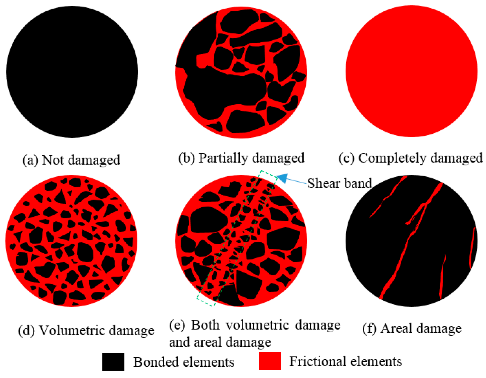
A breakage classification method for geomaterial, which is described by volume breakage ratios and area breakage ratios together, is proposed based on the binary-medium theory and the framework for the breakage mechanics of geological materials.
(2)
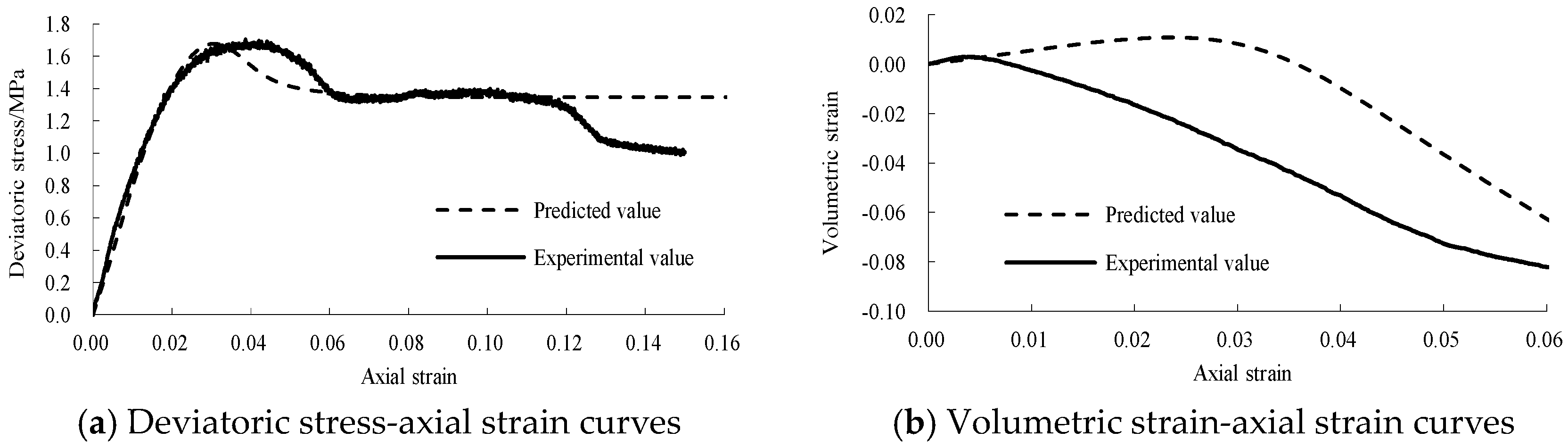
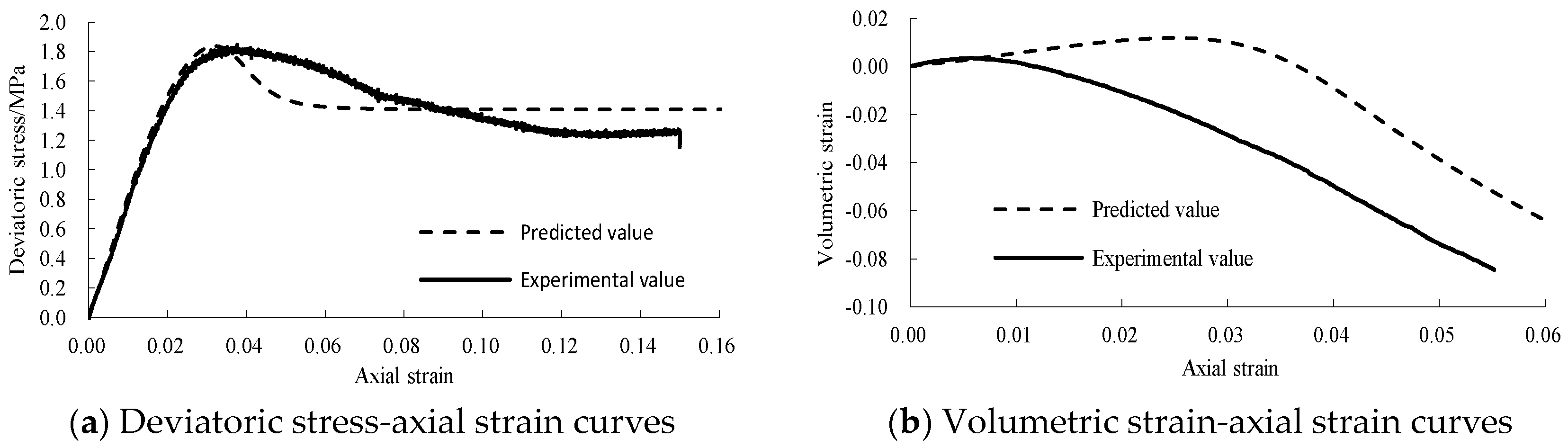
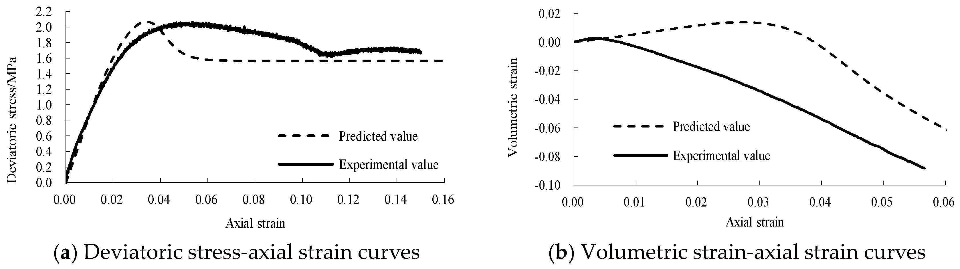
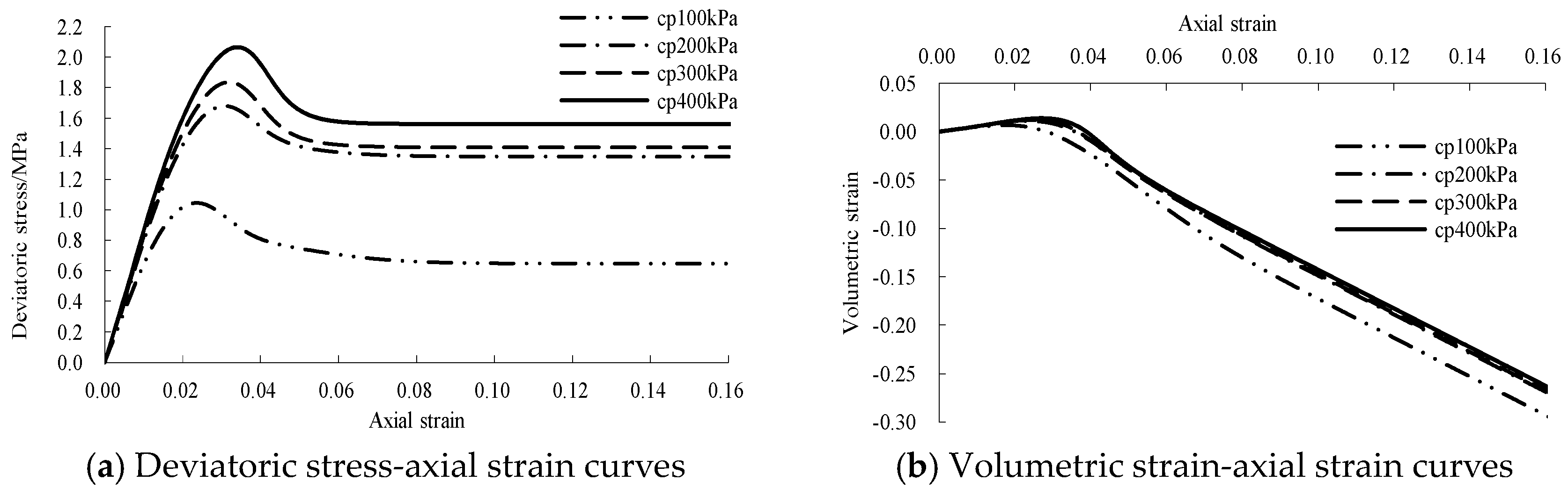
A static binary-medium model of jointed rock samples is obtained based on the Mohr–Coulomb yield criterion and the improved breakage ratio formula. The model was verified by static triaxial tests of jointed rock samples, and it was found that the proposed static binary-medium model can describe the stress–strain properties of jointed rock samples under different confining pressures. The strain-softening behavior, the volumetric strain characteristics and the influences of confining pressure on the strength and deformation behavior can be reflected well.
(3)
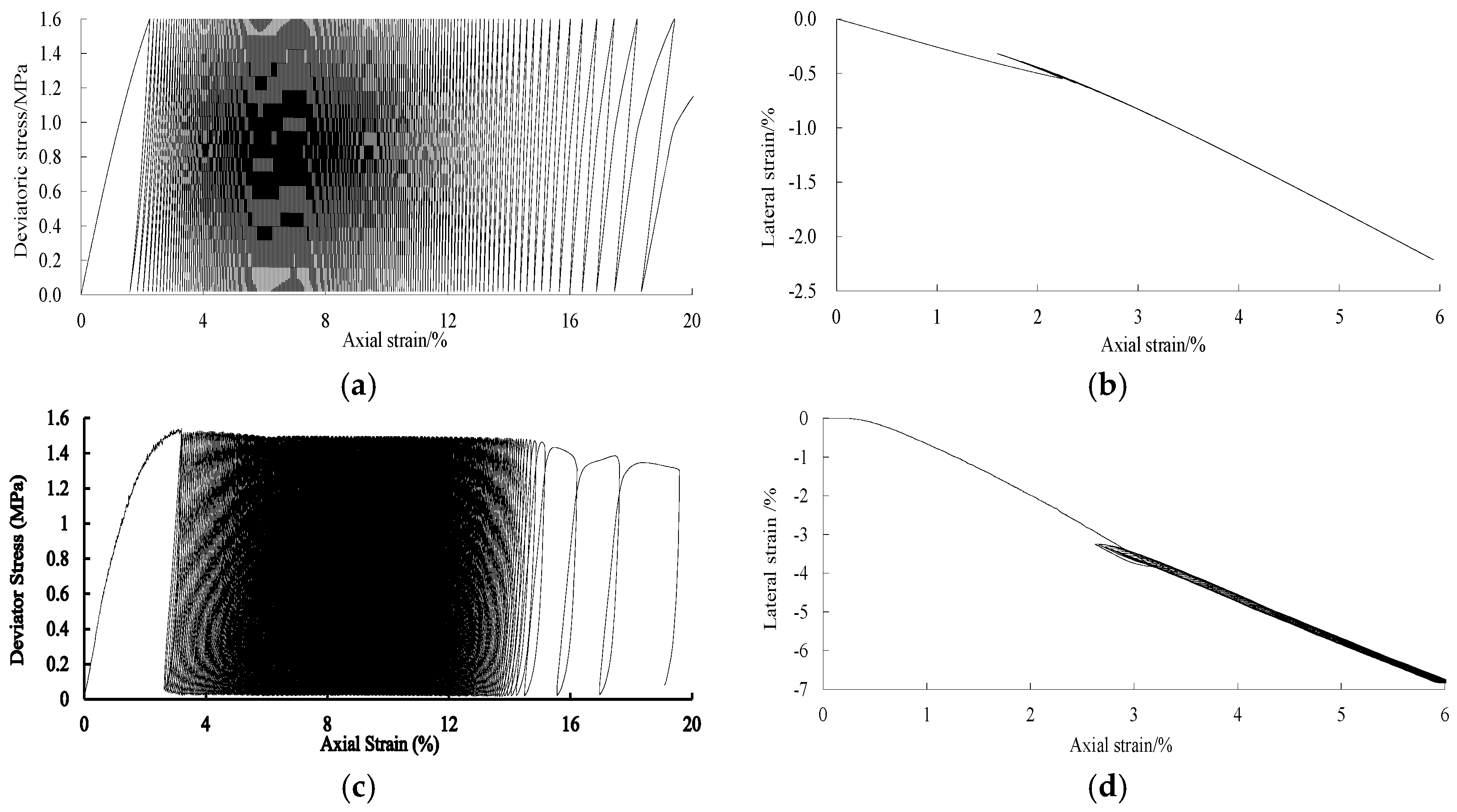
Based on the homogenization theory and the binary-medium theory, by introducing the breakage parameters and structural parameters and considering the influences of cyclic loading and unloading, the cyclic dynamic binary-medium model of jointed rock samples is established. It is found from the test verification that the predicted stress–strain curves using the dynamic model match with test results to a certain extent. They can describe the ratchet effect and the cyclic softening behavior well. They can effectively reflect the evolution laws of stress–strain curves varying from sparse to dense to sparse and the typical three-stage evolution laws of residual deformation. They describe the nonlinear stress–strain characteristics of the unloading and loading curves well and can reflect the effects of cyclic loading on the deformation and damage of jointed rock samples. Meanwhile, the lateral deformation characteristics are also described relatively well.

Author Contributions

Conceptualization, M.L. and E.L.; Methodology, M.L. and E.L.; Data curation, M.L.; Writing—original draft, M.L.; Writing—review and editing, E.L., M.L. and Q.Z.; Funding acquisition, M.L. and X.L.; Supervision, E.L., X.L. and Q.Z. All authors have read and agreed to the published version of the manuscript.

Funding

This work was supported by funding from the National Natural Science Foundation of China (Grant No. 52108319), the Natural Science Foundation of Jiangxi Province (20224BAB214069) and the Youth Science and Technology Innovation Talents of the Xinjiang Production and Construction Corps (2023CB008-28).

Data Availability Statement

The datasets used and analyzed during the current study are available from the corresponding authors upon reasonable request.

Conflicts of Interest

The authors declare no conflicts of interest.

References

  1. He, M.M.; Zhang, Z.Q.; Li, N. Experimental investigation and empirical model to determine the damping and shear stiffness properties of soft rock under multistage cyclic loading. Soil Dyn. Earthq. Eng. 2021, 147, 106818. [Google Scholar] [CrossRef]
  2. Mamou, A.; Powrie, W.; Clayton, C.; Priest, J.A. Suitability of empirical equations for estimating permanent settlement of railway foundation materials subjected to cyclic loading with principal stress rotation. Can. Geotech. J. 2021, 58, 1603–1610. [Google Scholar] [CrossRef]
  3. Cai, Y.Q.; Guo, L.; Jardine, R.J.; Yang, Z.X.; Wang, J. Stress-strain response of soft clay to traffic loading. Geotechnique 2017, 67, 446–451. [Google Scholar] [CrossRef]
  4. Taylor, L.M.; Chen, E.P.; Kuszmaul, J.S. Microcrack-induced damage accumulation in brittle rock under dynamic loading. Comput. Methods Appl. Mech. Eng. 1986, 55, 301–320. [Google Scholar] [CrossRef]
  5. Chen, E.P. Non-local effects on dynamic damage accumulation in brittle solids. Int. J. Numer. Anal. Methods Géoméch. 1999, 23, 1–21. [Google Scholar] [CrossRef]
  6. Song, J.; Kim, K. Micromechanical modeling of the dynamic fracture process during rock blasting. Int. J. Rock Mech. Min. Sci. Geomech. Abstr. 1996, 33, 387–394. [Google Scholar] [CrossRef]
  7. Shu, Y.; Zhu, Z.M.; Wang, M.; Ying, P.; Wang, F.; Wan, D.; Li, X.; Gao, W. A plastic damage constitutive model for rock-like material focusing on the hydrostatic pressure induced damage and the interaction of tensile and shear damages under impact and blast loads. Comput. Geotech. 2022, 15, 104921. [Google Scholar] [CrossRef]
  8. Lee, J.; Fenves, G.L. A plastic-damage concrete model for earthquake analysis of dams. Earthq. Eng. Struct. Dyn. 1998, 27, 937–956. [Google Scholar] [CrossRef]
  9. Wang, Z.; Li, Y.; Wang, J.G. A method for evaluating dynamic tensile damage of rock. Eng. Fract. Mech. 2008, 75, 2812–2825. [Google Scholar] [CrossRef]
  10. Liu, M.X.; Liu, M.X. Dynamic mechanical properties of artificial jointed rock samples subjected to cyclic triaxial loading. Int. J. Rock Mech. Min. Sci. Geomech. Abstr. 2017, 98, 54–66. [Google Scholar] [CrossRef]
  11. Jing, L.; Stephansson, O.; Nordlund, E. Study of rock joints under cyclic loading conditions. Rock Mech. Rock Eng. 1993, 26, 215–232. [Google Scholar] [CrossRef]
  12. Souley, M.; Homand, F.; Amadei, B. An extension to the Saeb and Amadei constitutive model for rock joints to include cyclic loading paths. Int. J. Rock Mech. Min. Sci. Geomech. Abstr. 1995, 32, 101–109. [Google Scholar] [CrossRef]
  13. Belem, T.; Souley, M.; Homand, F. Modeling surface roughness degradation of rock joint wall during monotonic and cyclic shearing. Acta Geotech. 2007, 2, 227–248. [Google Scholar] [CrossRef]
  14. White, A.J. Anisotropic damage of rock joints during cyclic loading: Constitutive framework and numerical integration. Int. J. Numer. Anal. Methods Géoméch. 2014, 38, 1036–1057. [Google Scholar] [CrossRef]
  15. Cui, Z.; Sheng, Q.; Leng, X.L.; Ma, Y. Analysis of the seismic performance of a rock joint with a modified Continuously Yielding model. Rock Mech. Rock Eng. 2017, 50, 2695–2707. [Google Scholar] [CrossRef]
  16. Li, Y.C.; Wu, W.; Tang, C.A.; Liu, B. Predicting the shear characteristics of rock joints with asperity degradation and debris backfilling under cyclic loading conditions. Int. J. Rock Mech. Min. Sci. Geomech. Abstr. 2019, 120, 108–118. [Google Scholar] [CrossRef]
  17. Xiao, J.Q.; Ding, D.X.; Xu, G.; Jiang, F.L. Inverted S-shaped model for nonlinear fatigue damage of rock. Int. J. Rock Mech. Min. Sci. Geomech. Abstr. 2009, 46, 643–648. [Google Scholar] [CrossRef]
  18. Zhou, S.W.; Xia, C.C.; Hu, C.C.; Zhou, Y. Damage modeling of basaltic rock subjected to cyclic temperature and uniaxial stress. Int. J. Rock Mech. Min. Sci. Geomech. Abstr. 2015, 77, 163–173. [Google Scholar] [CrossRef]
  19. Wang, Y.S.; Ma, L.J.; Fan, P.X.; Chen, Y. A fatigue damage model for rock salt considering the effects of loading frequency and amplitude. Int. J. Min. Sci. Technol. 2016, 26, 955–958. [Google Scholar] [CrossRef]
  20. Liu, Y.; Dai, F. A damage constitutive model for intermittent jointed rocks under cyclic uniaxial compression. Int. J. Rock Mech. Min. Sci. Geomech. Abstr. 2018, 103, 289–301. [Google Scholar] [CrossRef]
  21. Tian, J.Q.; Lai, Y.M.; Liu, E.L.; He, C. A thermodynamics-based micro-macro elastoplastic micropolar continuum model for granular materials. Comput. Geotech. 2023, 162, 105653. [Google Scholar] [CrossRef]
  22. Ren, C.H.; Yu, J.; Liu, X.Y.; Zhang, Z.Q.; Cai, Y.Y. Cyclic constitutive equations of rock with coupled damage induced by compaction and cracking. Int. J. Min. Sci. Technol. 2022, 32, 1153–1165. [Google Scholar] [CrossRef]
  23. Mo, H.H. Investigation of cyclic loading tests and constitutive relation of rock. Chin. J. Rock Mech. Eng. 1988, 7, 215. [Google Scholar]
  24. Feng, X.T.; Pan, X.T.; Zhou, H. Simulation of the rock microfracturing process under uniaxial compression using an elasto-plastic cellular automaton. Int. J. Rock Mech. Min. Sci. Geomech. Abstr. 2006, 43, 1091–1108. [Google Scholar] [CrossRef]
  25. Liu, E.L.; Zhang, J.H.; He, S.M.; Zhang, S.S.; Ge, K. Binary medium model of rock subjected to cyclic loading. J. Chongqing Inst. Technol. 2013, 27, 6–12. [Google Scholar]
  26. Li, Z.Z.; Nguyen, T.S.; Su, G.; Labrie, D.; Barnichon, J.D. Development of a viscoelastoplastic model for a bedded argillaceous rock from laboratory triaxial tests. Can. Geotech. J. 2017, 54, 359–372. [Google Scholar] [CrossRef]
  27. Zhou, Y.Q.; Sheng, Y.Q.; Li, N.N.; Fu, X.D.; Zhang, Z.P.; Gao, L.S. A Constitutive model for rock materials subjected to triaxial cyclic compression. Mech. Mater. 2020, 144, 103341. [Google Scholar] [CrossRef]
  28. Shen, Z.J.; Chen, T.L. Breakage mechanics for geological materials basic concepts, goal, and, task. In Proceedings of the 7th Academic Conference of Chinese Society of Rock Mechanics and Engineering, Beijing, China, 10–12 September 2002; pp. 9–12. [Google Scholar]
  29. Liu, E.L. Research on Breakage Mechanics of Structural Blocks and Binary Medium Model for Geomaterials. Doctoral Dissertation, Tsinghua University, Beijing, China, 2005. [Google Scholar]
  30. Liu, E.L.; Shen, E.L.; Chen, T.L. Experimental study on breaking process of prismatic structural bodies. Rock Soil Mech. 2006, 27, 93–98. [Google Scholar]
  31. Liu, M.X.; Liao, M.K.; Liu, E.L. Experimental research on mechanical properties of jointed rock mass with different angles of inclination. J. Beijing Univ. Technol. 2018, 44, 336–343. [Google Scholar]
Figure 1. Breakage diagram of geomaterial.
Mathematics 12 01765 g001
Figure 2. Simplified element combination of binary-medium material.
Mathematics 12 01765 g002
Figure 3. Conversion between bonded elements and frictional elements.
Mathematics 12 01765 g003
Figure 4. Evolution laws of breakage ratio.
Mathematics 12 01765 g004
Figure 5. The mold, the sample and the test apparatus: (a) the mold for preparing the samples, (b) the jointed rock sample with a 30° dip angle and (c) the GCTS dynamic triaxial apparatus.
Mathematics 12 01765 g005
Figure 6. Comparison between prediction and experiment of the static stress–strain curves and volumetric strain curves at confining pressure of 100 kPa.
Mathematics 12 01765 g006
Figure 7. Comparison between prediction and experiment of the static stress–strain curves and volumetric strain curves at confining pressure of 200 kPa.
Mathematics 12 01765 g007
Figure 8. Comparison between prediction and experiment of the static stress–strain curves and volumetric strain curves at confining pressure of 300 kPa.
Mathematics 12 01765 g008
Figure 9. Comparison between prediction and experiment of the static stress–strain curves and volumetric strain curves at confining pressure of 400 kPa.
Mathematics 12 01765 g009
Figure 10. Prediction of the static stress–strain curves and volumetric strain curves at different confining pressures.
Mathematics 12 01765 g010
Figure 11. Comparison between prediction and experiment of the cyclic triaxial tests at confining pressure of 200 kPa and with maximum deviator stress of 1600 kPa aiming at jointed rock samples with a 30° dip angle. (a) Predicted deviatoric stress–axial strain curve; (b) predicted lateral strain–axial strain curve; (c) experimental deviatoric stress–axial strain curve; (d) experimental lateral strain–axial strain curve.
Mathematics 12 01765 g011
Table 1. Parameters of static binary-medium model.
Bonded ElementsFrictional Elements
Confining Pressure E c /MPa μ c E f /MPa μ f sin ϕ
100 kPa700.25250.30.54
200 kPa750.25250.30.54
300 kPa800.25250.30.54
400 kPa850.25250.30.54
Table 2. Breakage and structure parameters of the static binary-medium model.
Confining Pressure r s p s q s p v q v t s t v
100 kPa275501.52501.50.0010.05
200 kPa274551.53001.50.0010.05
300 kPa274031.53501.50.0010.05
400 kPa273641.54001.50.0010.05
Table 3. Parameters of the dynamic binary-medium model.
ParametersMonotone Loading UnloadingLoading
Bonded elements K 0 c /MPa56.6756.6756.67
E 0 f /MPa343434
E 0 f −0.21.51.4
E 0 f −0.030.80.7
Frictional elements E 0 f /MPa252525
φ f −0.020.450.40
φ f 0.30.30.3
φ f /MPa0.30.30.3
φ f 35°35°35°
Table 4. Breakage and structure parameters of the dynamic binary-medium model.
a s n s a v n v m s m v
601.54001.50.0010.05
Disclaimer/Publisher’s Note: The statements, opinions and data contained in all publications are solely those of the individual author(s) and contributor(s) and not of MDPI and/or the editor(s). MDPI and/or the editor(s) disclaim responsibility for any injury to people or property resulting from any ideas, methods, instructions or products referred to in the content.

