Article

Room Temperature UV-Activated NO2 and NO Detection by ZnO/rGO Composites

1
Chemistry Department, Moscow State University, 119991 Moscow, Russia
2
Faculty of Materials Science, Moscow State University, 119991 Moscow, Russia
*
Author to whom correspondence should be addressed.
Chemosensors 2023, 11(4), 227; https://doi.org/10.3390/chemosensors11040227
Submission received: 27 February 2023 / Revised: 1 April 2023 / Accepted: 3 April 2023 / Published: 6 April 2023
(This article belongs to the Collection Women Special Issue in Chemosensors and Analytical Chemistry)

Abstract

:
Nanocomposites, including nanoparticles of semiconductor metal oxide (MO) and reduced graphene oxide (rGO), are of exceptional interest for light-activated gas sensors functioning without thermal heating. In this paper, we discuss the sensor properties of electrospun ZnO nanofibers and ZnO/rGO composites. The materials were characterized by transmission and scanning electron microscopy (TEM, SEM), X-ray diffraction (XRD), X-ray photoelectron spectroscopy (XPS), and IR spectroscopy (FTIR). The sensor characteristics were studied when detecting reducing gases CO, H2, and NH3 and oxidizing gases NO and NO2 at 25–150 °C in dark conditions and under UV illumination. ZnO nanofibers and ZnO/rGO composites have no sensitivity when detecting CO, NH3, and H2 either in dark conditions or under UV illumination. At T = 25 °C, UV illumination is a necessary condition for the appearance of a sensor response when detecting both NO and NO2. The increased sensitivity of ZnO/rGO composites when detecting nitrogen oxides at T = 25 °C is discussed in terms of the heterojunction formation. Observed at T = 150 °C, opposite trends in the UV illumination influence on the sensor response toward NO and NO2 are due to the participation of chemisorbed oxygen in the processes responsible for the sensor response formation when detecting NO.

1. Introduction

The unique electronic, optical, photoelectric, and mechanical properties of graphene, due to the peculiarities of its structure, stimulated the creation of new materials with a layered 2D structure and numerous studies of their functional properties aimed at the development of optoelectronic converters, field-effect transistors, photovoltaic devices, transparent electrodes, LEDs, catalysts, etc. [1,2]. Two-dimensional materials are of exceptional interest for gas sensors, since they combine, on the one hand, the maximum surface-to-volume ratio, which ensures high adsorption capacity and reactivity when interacting with gases, and, on the other hand, the presence of predominantly one crystallographic plane with high perfection of the crystal structure, which improves the dynamic properties of sensors, reducing time response and relaxation of the signal.
For graphene, the physical adsorption of gases occurs at carbon atoms, the C-C bond center, and the center of the carbon atom hexagon [3,4,5,6,7,8]. Chemical or thermal functionalization of graphene, the creation of graphene oxide (GO), and reduced graphene oxide (rGO) can significantly increase the reactivity of the material due to the formation of chemically bound oxygen, hydroxyl, carboxyl, and carbonyl groups on its surface [4,6].
More recently, research interests have turned to the development of 2D/MO nanocomposites, including nanoparticles of semiconductor metal oxide (MO) [9,10,11,12,13,14,15]. One of the features of such systems is the possibility of obtaining a sensor response at sufficiently low operating temperatures, down to room temperature [9,10]. At the same time, additional advantages in terms of increasing sensitivity can be obtained with UV photo-activation using low-power LEDs [16,17]. UV LEDs are able to produce exact wavelengths at a specific intensity with low energy consumption (about tens of mW) for optimum working conditions [18]. Thus, the creation of gas sensors operating under photoactivation conditions is a new, actively developing direction [18,19,20,21,22,23], associated with the development of highly sensitive sensors with low energy consumption (Table 1).
In this paper, nanocomposites based on electrospun ZnO nanofibers and ZnO/rGO composites with different rGO contents are discussed. We focused on a comparative study of sensor properties of obtained materials when detecting nitrogen oxides (NO2 and NO) at low temperatures of 25–150 °C in dark conditions and under UV illumination. The experimental results show that UV photoactivation provides the sensitivity of ZnO/rGO composites toward NO2 and NO at room temperature.

2. Materials and Methods

2.1. Materials Synthesis

Polyvinylpyrrolidone (PVP) (Mw = 1,300,000, Sigma-Aldrich, St. Louis, MO, USA), zinc acetate (Zn(CH3COO)2 × 2H2O, Sigma-Aldrich, 99%), 2-methoxyethanol (CH3OCH2CH2OH, Sigma-Aldrich, 99.8%), isopropyl alcohol (C3H7OH, Sigma-Aldrich, 99.9%) were used without additional purification. The reduced graphene oxide was synthesized by the modified Hammer’s method at Lition LLC (Dubna, Russia).
To obtain ZnO nanofibers by the electrospinning method, 1.25 g of zinc acetate was dissolved in 50 mL of a mixture of isopropyl alcohol and 2-methoxyethanol (1:1). Then, 4.5 g of PVP was added to this solution and mixed until the polymer was completely dissolved. The resulting polymer solution was transferred to a medical syringe with a 21G metal needle (inner diameter 510 μm). The solution was continuously pumped with a syringe pump at a rate of 1 mL/h. The voltage between the needle and the collector was 10 kV, the distance was 13 cm. Finally, the obtained fibers were annealed in air at 550 °C for 5 h, the heating rate of the furnace was 1 K/min.
Composites ZnO/rGO containing 0.5, 1, and 2 wt.% rGO were prepared by impregnation of synthesized ZnO nanofibers with rGO suspension in isopropyl alcohol, followed by drying at room temperature for 12 h. For uniform distribution of rGO over the surface of ZnO, impregnation was carried out in an ultrasonic bath, the duration of ultrasonic treatment was 15 min.

2.2. Materials Characterization

The phase composition of the samples was determined by powder X-ray diffraction (XRD) using a DRON-4-0.7 diffractometer (Burevestnik, St. Petersburg, Russia) with an X-ray wavelength λ = 1.54051 (CuKα radiation). The average size of the crystallites was calculated using the Scherrer formula:
d X R D = k · λ β · cos Θ ,
where dXRD is the average size of the coherent scattering region, β is the width of the corresponding diffraction peak at half the height, λ is the wavelength of the radiation used, θ is the diffraction angle, k is the shape coefficient for spherical particles (k = 0.9).
The composition of the surface was characterized by Infrared Fourier spectroscopy (FTIR) using a Perkin Elmer Frontier spectrometer (Perkin Elmer Inc., Beaconsfield, UK). The spectra were recorded in the transmission mode in the wavenumbers range of 4000–400 cm−1 with a step of 4 cm−1. During sample preparation, 0.5 mg of sample powder was ground with 50 mg KBr and pressed into tablets with a diameter of 7 mm.
The microstructure of the materials was studied by scanning electron microscopy (SEM) using a Carl Zeiss NVision 40 microscope (Carl Zeiss, Inc., Oberkochen, Germany). The experiments were carried out using an intralens secondary electron detector at an accelerating voltage of 10 kV with an aperture of 30 μm. The samples were applied to a conductive double-sided carbon adhesive tape glued to the microscope sample holder.
The charge state of zinc, oxygen, and carbon atoms in ZnO nanofibers and ZnO/rGO nanocomposites was determined by X-ray photoelectron spectroscopy (XPS) using an Axis Ultra DLD spectrometer (Kratos Analytical, Manchester, UK) with monochromatic Al Kα radiation (hν = 1486.7 eV, 150 W) in a vacuum not lower than 10−9 torr. The charge shift was compensated by the C1s ground state peak with a binding energy of 285 eV for ZnO samples and ZnO/rGO composites, and for the rGO sample by a peak with a binding energy of 284.5 eV. Survey spectra in the range of 600–0 eV with 0.5 eV increments were obtained for all samples. The spectra of the Zn2p, O1s, and C1s regions were recorded with increments of 0.05 eV. The background was described using the Shirley method, the spectra were approximated by mixed Gauss-Lorentz functions.

2.3. Measurements of the Gas Sensor Properties

The sensor properties of the ZnO nanofibers and ZnO/rGO nanocomposites were studied in situ by measuring the conductivity of thick films using a laboratory-developed installation with a flow chamber. Materials in the form of a paste with isopropanol were applied to a 2 × 2 × 0.5 mm aluminum oxide substrate with Pt electrodes (on the top side) and Pt microheaters (on the back side). After applying the paste, the substrates were dried for 5 h at room temperature in laboratory air, then heated to 150 °C (2 K/min) and kept for 5 h to completely remove the solvent. Despite the fact that graphene oxide begins to break down in air at temperatures above 400 °C [17], at 180 °C, the burnout of rGO from ZnO/rGO composites begins, which is accompanied by a change in the color (bleaching) of the sensitive layer and instability of the sensor’s resistance to air. For this reason, when preparing sensors and taking measurements, the temperature did not exceed 150 °C. The resistance of the sensors was measured at a constant voltage in a controlled gas flow of 100 ± 0.1 mL/min in the temperature range of 25–150 °C in dark conditions and under illumination by UV LED (λmax = 365 nm). The power consumption of UV LED illuminating 4 sensors was 125 mW. The power consumption of each sensor in thermal heated measurements was 82, 136, and 300 mW at a temperature of 100, 150 and 300 °C, respectively. Attested gas mixtures were used as sources of analyte gases. Gas mixtures with a preassigned concentration of CO (20 ppm), NH3 (20 ppm), H2 (100 ppm), NO (4 ppm), and NO2 (1 ppm) in dry air were created using electronic gas flow regulators RRG12 (Eltochpribor, Zelenograd, Russia). The concentrations of NO and NO2 in gas mixtures were additionally verified with a Teledyne API N500 CAPS NOX Analyzer. The sensor signal S when detecting reducing gases was calculated by the formula (2):
S = R a i r R g a s R g a s = R a i r R g a s 1 ,
In the case of oxidizing gases, the formula (3) was used:
S = R g a s R a i r R a i r = R g a s R a i r 1 ,
where R a i r —resistance of the material in the background air; R g a s —resistance of the material in the presence of an analyte gas.

3. Results

3.1. Structure, Morphology, and Surface Characterization

Diffractograms of rGO, ZnO nanofibers, and ZnO/rGO nanocomposites are shown in Figure 1. The rGO diffractogram has two characteristic peaks at 2θ = 24.10° and 42.60°. The first one is associated with the π-conjugate graphene structure which indicates the similarity of rGO and graphene [54,55]. The second one is explained by the disordered arrangement of graphene layers [56]. The diffractogram of ZnO nanofibers corresponds to zinc oxide with a wurtzite structure (ICDD [36–1451]). In the case of composites with different rGO content, the main phase is the zinc oxide phase with a wurtzite structure. For all samples, the average size of the ZnO crystal grains estimated by Equation (1) was dXRD = 15 ± 1 nm. No reflections corresponding to rGO were detected; however, there is a small new peak, which is apparently associated with the presence of disordered graphite layers (T-carbon, [57]). The wide peak at 20° present on the diffractograms of all samples corresponds to the cuvette material, as confirmed by the diffractogram of an empty cuvette.
Figure 2 and Figure 3 demonstrate SEM and TEM images of ZnO nanofibers, rGO, and a ZnO/rGO nanocomposite. ZnO nanofibers obtained by electrospinning have a three-dimensional spongy structure formed by fibers with an average diameter of 200 nm (Figure 2a). The fibers, in turn, consist of smaller crystalline particles with a size of 20–50 nm (Figure 3a). The reduced graphene oxide is micrometer-sized sheets (Figure 2b) with a thickness of about 10–100 nm (Figure 3b) that may indicate a multilayer rGO structure. SEM image of the ZnO/rGO composite (Figure 2c) indicates that the fibrous structure of ZnO was not preserved. The destruction of nanofibers could occur during ultrasonic processing used for impregnating the ZnO fibers with rGO suspension. The TEM image (Figure 3c) confirms the presence of the same “primary” components—ZnO nanoparticles and rGO sheets.
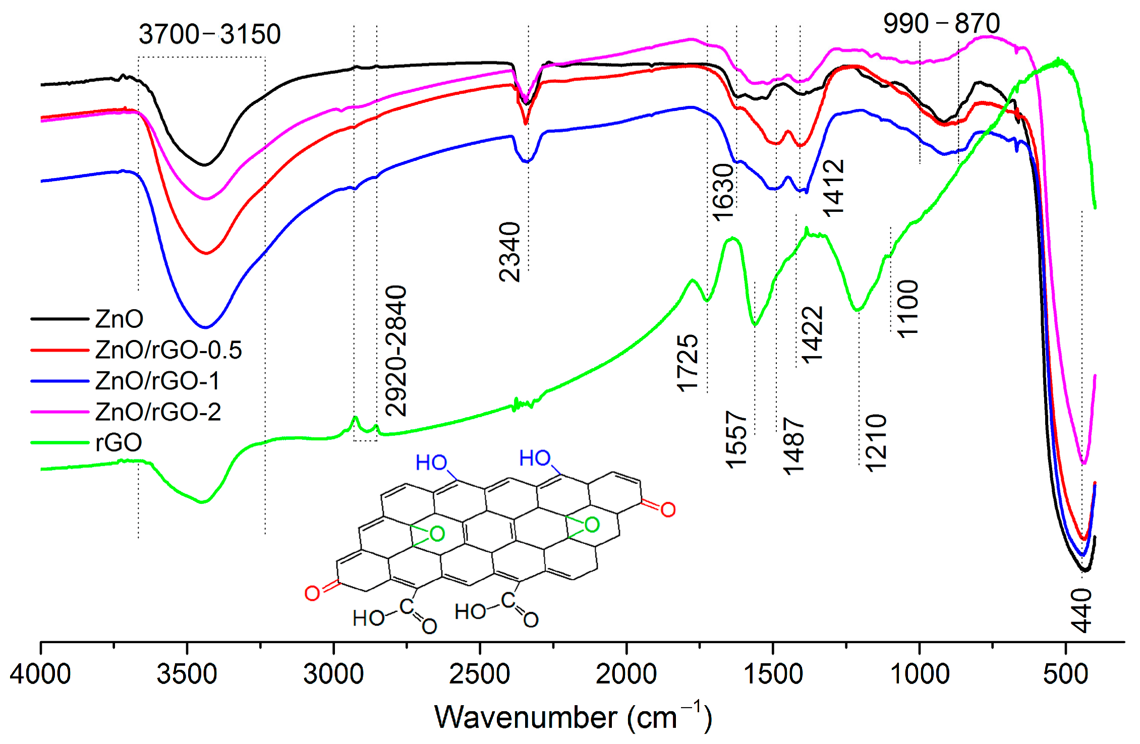
The FTIR spectrum of ZnO nanofibers (Figure 4) contains characteristic absorption bands corresponding to O–H bonds (3700–3150 cm−1) from physically and chemically adsorbed hydroxyl groups, C–H bonds (2920–2840 cm−1) from fragments of organic molecules, and C=O bonds (2340 cm−1) from adsorbed CO2 molecules. The band at 1630 cm−1 corresponds to deformation vibrations of adsorbed water molecules, the bands at 990–870 cm−1 can be associated with multi-phonon vibrations of the ZnO lattice, and finally, the 440 cm−1 band characterizes valence Zn–O vibrations in the zinc oxide crystal structure.
The absorption spectrum of rGO, in addition to the bands at 3700–3150 cm−1 and 2920–2840 cm−1 associated with O–H and C–H bonds, contains absorption bands characteristic for carbonyl C=O (1725 cm−1), carboxyl–COOH (1487 cm−1), epoxy C–O–C (1210 cm−1), and alkoxyl C–O (1100 cm−1) groups, as well as bands characteristic for vibrations of sp2-hybridized C–C bonds (1557 cm−1) and an OH-group bonded with graphene carbon (1422 cm−1). The presence of a large number of carboxyl and alkoxyl groups on the rGO surface indicates a weak reduction of graphene oxide, which will inevitably affect its electrical properties and, consequently, the gas-sensitive characteristics of ZnO/rGO composites.
In comparison with the spectrum of ZnO nanofibers, additional absorption bands were found in the FTIR spectra of ZnO/rGO composites at 1412 cm−1, corresponding to vibrations of tertiary C–OH bonds, and at 1487 cm−1, due to carboxyl groups. The appearance of these bands is obviously related to the presence of rGO in ZnO/rGO composites.
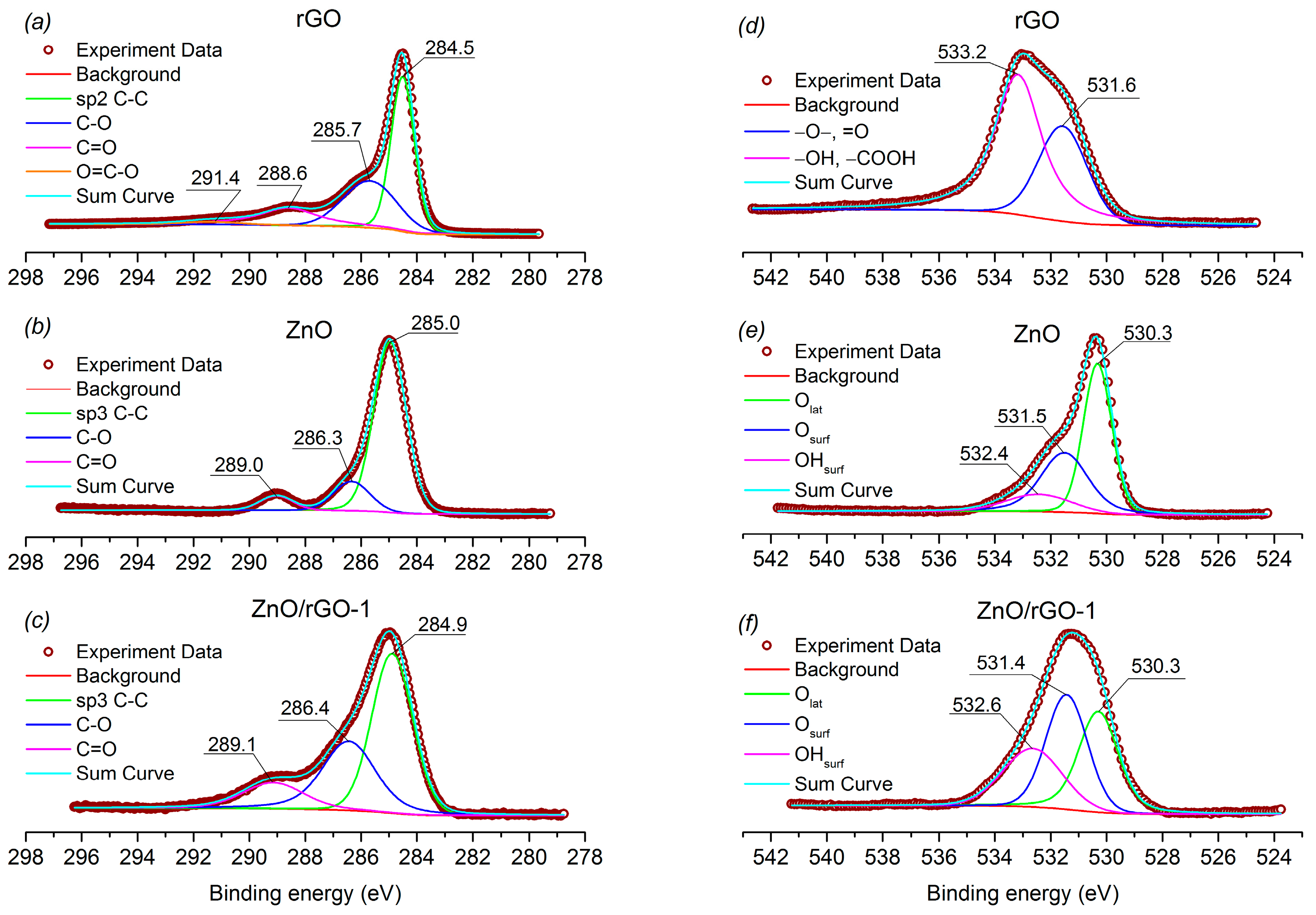
The X-ray photoelectron spectra confirm the presence of various oxygen-containing groups on the rGO surface. Figure 5a shows the C1s region of the rGO XP- spectrum, containing components with binding energies of 284.51, 285.68, 288.6, and 291.38 eV corresponding to carbon in sp2-hybridized C–C bonds, alkoxyl C–O, carbonyl C=O, and carboxyl COOH groups, respectively. The O1s region of the rGO spectrum (Figure 5d) contains two components with binding energies of 531.56 and 533.16 eV, which can be attributed to oxygen in the alkoxyl C–O and carbonyl C=O groups, and oxygen in the hydroxyl OH and carboxyl COOH groups, respectively. The fraction of hydroxyl OH and carboxyl COOH groups is 65%, and alkoxyl C–O and carbonyl C=O groups is 35%.
The spectra of ZnO nanofibers (Figure 5b) and the ZnO/rGO-1 composite (Figure 5c) in the C1s region contain three components with binding energies of 284.97, 286.34, 289.03 eV (ZnO) and 284.88, 268.44, 289.14 eV (ZnO/rGO-1), which can be attributed to amorphous carbon, alkoxyl C–O, and various ether groups, respectively. It is worth noting a significant increase in the integral intensities of the components responsible for carbon in the C–O and ether groups in the spectrum of the composite ZnO/rGO (33% and 14%) compared with the spectrum of ZnO nanofibers (15% and 7%).
The spectra of ZnO (Figure 5e) and ZnO/rGO-1 (Figure 5f) in the O1s region also contain three components: 530.32, 531.51, 532.44 eV (ZnO) and 530.29, 531.42, 532.64 eV (ZnO/rGO-1), corresponding to the oxygen of the ZnO crystal structure (Olat), different forms of chemisorbed oxygen (Osurf), and adsorbed OH groups (OHsurf), respectively. There is an increase in the integral intensity of the components corresponding to chemisorbed oxygen and OH groups in the spectrum of the ZnO/rGO-1 composite (([Osurf] + [OHsurf])/[Olat] = 1.9) compared with pure ZnO (([Osurf] + [OHsurf])/[Olat] = 1.0).

3.2. Gas Sensor Properties

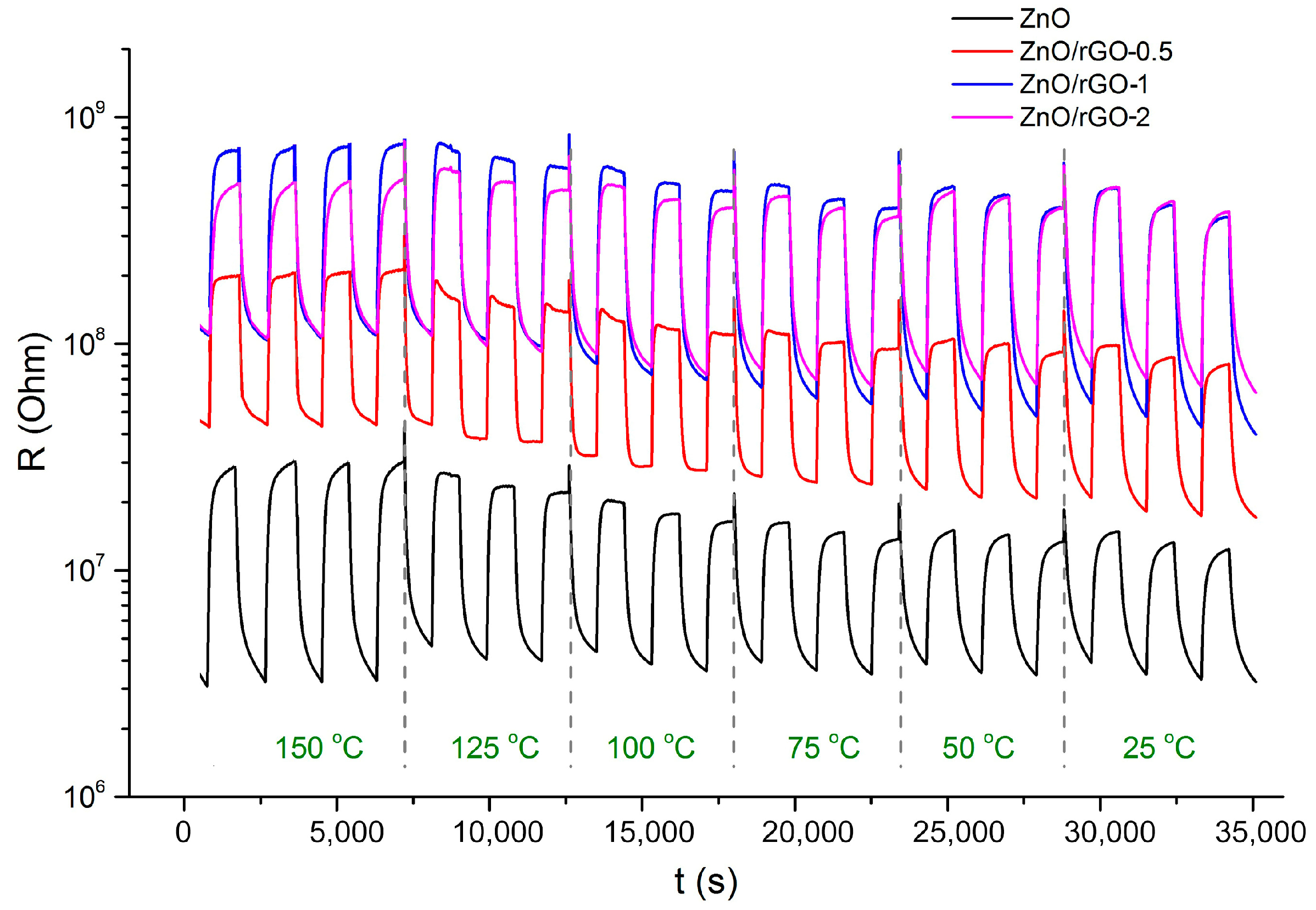
The sensor properties of ZnO nanofibers and ZnO/rGO composites were studied toward reducing gases (CO 20 ppm, NH3 20 ppm, H2 100 ppm) and oxidizing gases (NO2 1 ppm, NO 4 ppm) in a temperature range of 25–150 °C in dry air in dark conditions and under constant UV illumination (365 nm). For all samples, a reversible change in resistance is observed when NO or NO2 is introduced into the measurement cell and its subsequent recovery when purged with clean air. The dynamic response of the sensor to 1 ppm NO2 under constant UV illumination is shown in Figure 6 as an example.
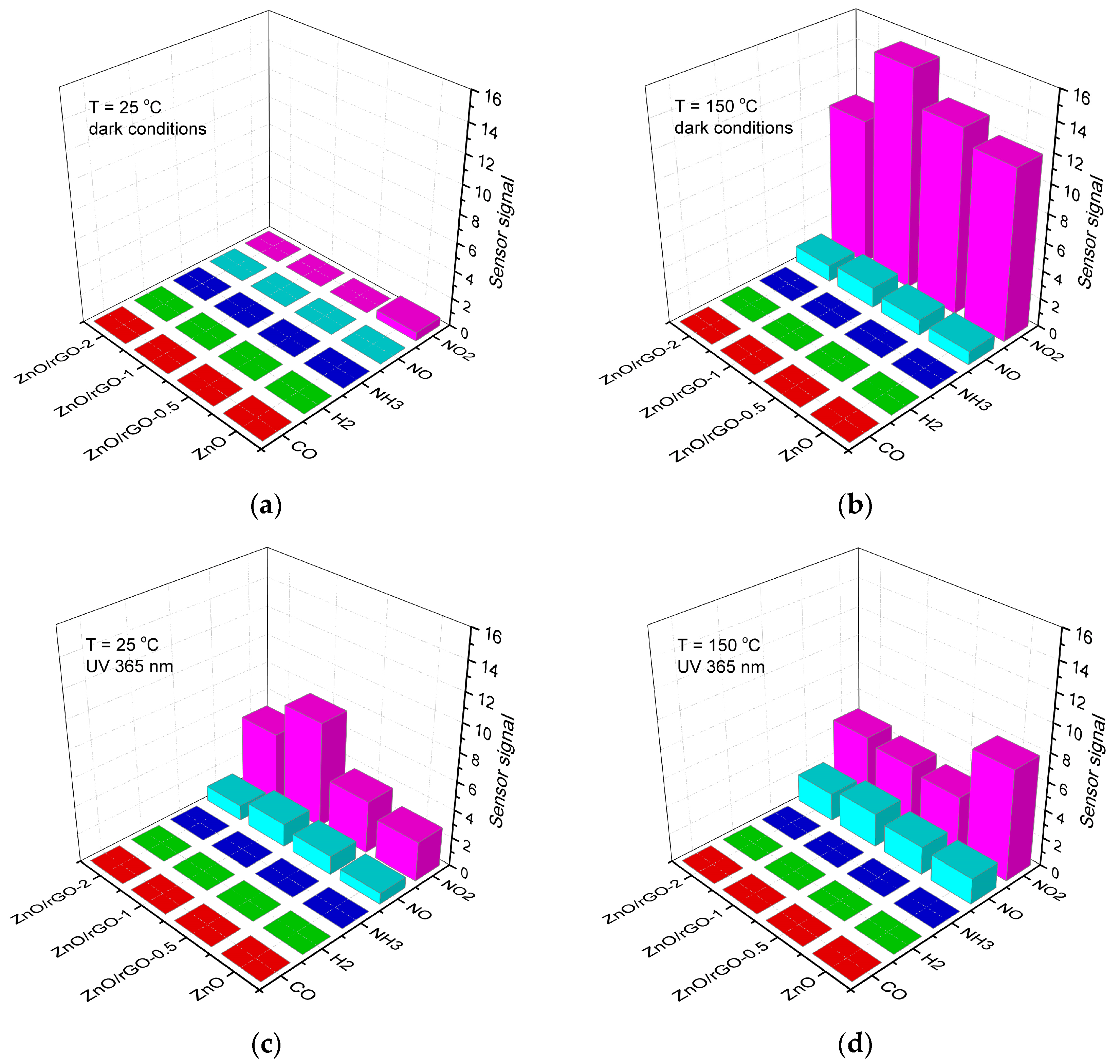
Figure 7 presents the values of the sensor signal of ZnO nanofibers and ZnO/rGO composites when detecting the gases under study at temperatures of 25 and 150 °C in dark conditions and under constant UV illumination. In dark conditions at a room temperature of 25 °C (Figure 7a), all the materials do not exhibit sensor sensitivity to all gases, both reducing and oxidizing. With an increase in the operating temperature to 150 °C (Figure 7b), the sensor sensitivity of materials to oxidizing gases, especially nitrogen dioxide, appears.
Under UV illumination, the situation is changing. Both at a room temperature of 25 °C (Figure 7c) and at T = 150 °C (Figure 7d), the sensor sensitivity of ZnO nanofibers and ZnO/rGO composites to oxidizing gases NO and NO2 is observed. To the reducing gases CO, NH3, and aH2, as in dark conditions, all materials do not show a sensor response. In particular, the materials exhibit selective sensor sensitivity to NO2 in the entire temperature range of 25–150 °C, and at T = 150 °C, a sensor based on ZnO nanofibers has the greatest response, while at T = 25 °C, the ZnO/rGO-1 composite provides the best characteristics.

4. Discussion

4.1. Electrical Properties of ZnO/rGO Interface

To explain the observed trends in the sensor properties of ZnO nanofibers and ZnO/rGO composites, it is necessary to discuss the electrical properties of the heterojunction formed between ZnO and rGO. Zinc oxide is a wide-band n-type semiconductor. The weak reduction of graphene oxide shown by the FTIR and XPS methods brings it closer to p-type doped graphene oxide GO [58]. Indirectly, this assumption is confirmed by the temperature dependences of the resistance of ZnO nanofibers and ZnO/rGO composites (Figure 8). On the temperature dependences of the resistance in lgR vs. 1/T coordinates, two regions can be distinguished. The linear region in the temperature range 75–150 °C reflects the activation character of the conductivity of ZnO and ZnO/rGO composites, and the activation energy of the conductivity of ZnO/rGO composites turns out to be greater than for ZnO. In the range of 25–75 °C, the resistance values are practically independent of temperature. With UV illumination, there is a significant decrease in the resistance of materials (Figure 8b). Under these conditions, the resistance of ZnO and ZnO/rGO composites practically does not depend on temperature.
It can be noted that the temperature dependences of the resistance of ZnO/rGO composites have the same form as the temperature dependences of the resistance of ZnO nanofibers both in dark conditions and under UV illumination. That is, the mechanism of electrical conductivity of ZnO/rGO composites is determined by the properties of ZnO. Under dark conditions in the temperature range of 150–75 °C, the activation character of ZnO conductivity indicates the presence of energy barriers at the boundaries of ZnO grains due to the localization of electrons by chemisorbed oxygen (Equation (4)) and the formation of a near-surface layer depleted in electrons compared to the bulk of the semiconductor.
O 2 g a s + e O 2 a d s
The length of this electron-depleted layer L is determined by the Debye length in this material LD and the height of the Schottky surface barrier Vs [59].
L = L D q V s k B T ,
where q is the electron charge, kB is the Boltzmann constant, T is the absolute temperature. The Debye length in the material is determined by the equation
L D = ε ε 0 k B T q 2 n b ,
where ε is the dielectric constant of the material, nb is the bulk electron concentration.
The value of the surface barrier, in turn, is determined by the charge of the surface Q s 2 :
V s = Q s 2 2 · ε ε 0 q n b .
From Equation (6), it can be expected that the LD value should decrease with decreasing temperature (LD~T1/2). However, in the case of semiconductors, the bulk concentration of charge carriers nb also decreases significantly with a decrease in temperature which should lead to an increase in LD (LD~nb−1/2). For nanocrystalline SnO2, it is shown [60] that with a decrease in temperature, the LD value integrally increases. In combination with Equation (5), this allows us to expect an increase in the length of the electron-depleted layer L in the case of ZnO. Calculations carried out by the authors [61] show that at room temperature, the LD value in zinc oxide is 19 nm. Therefore, the ratio dXRDLD is implemented and the weak dependence of the ZnO resistance on the temperature in the range of 75–25 °C may be due to the spread of the electron-depleted layer over the entire ZnO crystalline grain and the transition of the band structure to the flat band situation [60]. In this case, the conductivity is determined by the electron concentration in the depleted layer, which is reflected by the Fermi level position, and intercrystalline barriers (providing the activation character of conductivity) do not significantly contribute to electrical conductivity (Figure 9).
Under dark conditions (Figure 8a), ZnO/rGO composites have resistance 1.5–2 orders of magnitude greater than pure ZnO which may be due to the formation of p-n heterojunctions at the n-ZnO/p-rGO interface. The ratio of the electron work functions φ for n-ZnO (φ = 4.6 eV [62]) and rGO (depending on functionalization and total oxygen content φ = 5.5–4.7 eV [63,64,65]) is such that when equilibrium is established on the n-ZnO/p-rGO interface, electron transfer from ZnO to rGO occurs. This leads to the formation of a depletion layer at the ZnO/rGO interface that makes the electron transport channel narrower and results in an increase in the resistance of ZnO/rGO composites compared with ZnO nanofibers.
UV illumination leads to the generation of electrons and holes and, consequently, to a significant increase in the bulk electron concentration for n-ZnO. As a result, the Debye length LD (Equation (6)) and the height of the surface barrier (Equation (7)) decrease simultaneously. Thus, the conductivity of ZnO and, consequently, ZnO/rGO composites becomes weakly dependent on temperature in the entire range of 25–150 °C (Figure 8b).
Figure 8c shows the temperature dependence of the UV illumination effect on the resistance of ZnO and ZnO/rGO composites. The ratio Rdark/RUV, where Rdark is the resistance in dark conditions and RUV is the resistance under illumination, is selected as an illustrative parameter. The value of Rdark/RUV increases significantly with a decrease in temperature from 150 to 75 °C, and then changes slightly. Obviously, ZnO and ZnO/rGO composites at room temperature demonstrate a large photo response, because they have very low dark conductivity. Therefore, even small in absolute magnitude photocurrents will give a large photoresponse. When the semiconductors are heated, the dark current increases. In addition, the photocurrent that is generated during illumination remains in approximately the same order. UV illumination obviously leads to a decrease in the work function of both ZnO (about 0.3 eV [66]) and rGO (about 0.05 eV [67]), but the ratio φ(ZnO) < φ(rGO) is maintained that provides a higher RUV resistance of ZnO/rGO composites compared to ZnO.
It is known [19] that the presence of oxygen in the gas phase significantly affects the photoconductivity of semiconductors, while in the environment of various inert gases and in a vacuum, photoconductivity behaves in a similar way. This indicates an interaction between photoexcited charge carriers and oxygen particles present on the surface of semiconductor oxides in ion-adsorbed forms. Thus, an increase in the concentration of photogenerated electrons eph should lead to chemisorption of an additional amount of oxygen on its surface, i.e., to photoadsorption:
O 2 ( g a s ) + e p h O 2 ( a d s )
A photogenerated hole hph, on the contrary, can cause desorption of chemisorbed oxygen:
O 2 ( a d s ) + h p h + O 2 ( g a s )
As a result of this process, the oxygen molecule passes into a neutral physically adsorbed form, which can then be easily removed from the surface due to thermal fluctuations, and the electron captured by oxygen returns to the semiconductor. The peculiarity of this process is that the absorption of one photon actually leads to the formation of two electrons in the crystal. Thus, the steady-state conductivity of metal oxides in air under UV illumination, as well as their dark conductivity, is significantly controlled by the processes of chemisorption and desorption of oxygen [68,69]. The “photoadsorption–photodesorption” equilibrium is determined by the type and concentration of defects, as well as the metal-oxygen bond energy for the given semiconductor oxide [69]. The interaction of electron acceptor gases (O3, NO2) with semiconductor oxides under photoactivation conditions involves the same processes of photoadsorption and photodesorption [18,70,71]. The conductivity value in this case will depend on the electron affinity of a particular gas molecule, as well as the concentration of oxygen and the detected gas.

4.2. NO2 Detection

The results of earlier DRIFTS investigations [72,73] indicate that the interaction of NO2 with the surface of n-type semiconductors includes the following processes:
N O 2 g a s + e N O 2 a d s ,
N O 2 ( g a s ) + O 2 ( a d s ) N O 2 ( a d s ) + O 2 ( g a s ) ,
2 N O 2 ( g a s ) + 1 2 O 2 ( g a s ) + 2 e N O 2 ( a d s ) + N O 3 ( a d s ) ,
N O 2 ( a d s ) + 1 2 O 2 ( g a s ) N O 3 a d s .
Since NO2 has a greater electron affinity (2.27 eV [74]) than oxygen (0.44 eV [75]), the equilibria (10)–(12) are shifted towards the formation of the chemisorbed form of NO2. Consequently, even in conditions of high oxygen concentration (about 20% in air), the NO2 presence at ppm level turns out to be a factor determining the conductivity of ZnO. The authors [76] have shown by the example of SnO2 that the conductivity of n-type semiconductor metal oxides in NO2-containing atmospheres correlates with the concentration of surface bidentate nitrites [76]. Compared to chemisorbed oxygen, these NO2 species form in the zinc oxide band gap deeper acceptor levels, the position of which can be estimated as 1.2–2.3 eV below the bottom of the ZnO conduction band [77].
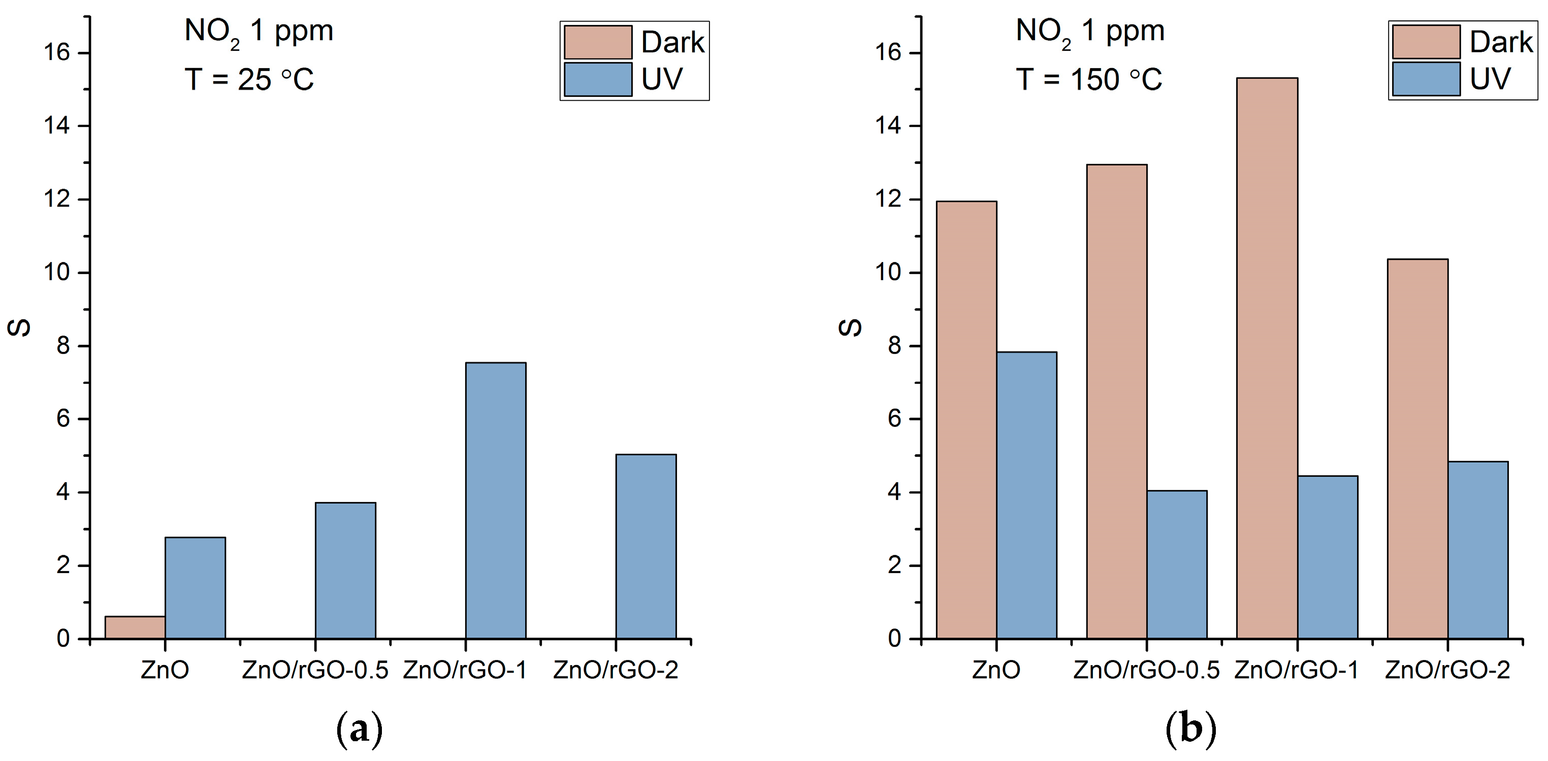
Localization of electrons at NO2 acceptor level leads to an increase in the resistance of n-type semiconductor oxide. When detecting NO2 at 25 °C in the dark, the resistance of ZnO/rGO composites becomes higher than 1011 Ohms (the measurement limit of our device) which does not allow us to determine the sensor response for these materials (Figure 10a). Comparison of the position of the Fermi level for ZnO and ZnO/rGO composites at 25 °C in the dark with the position of NO2 acceptor level (Figure 9) suggests a lower signal towards NO2 in the case of ZnO/rGO composites. An increase in temperature up to 150 °C leads to a decrease in the resistance of ZnO and ZnO/rGO composites by about three orders of magnitude (Figure 8a) which makes it possible to reliably register a sensor response towards NO2. At the same time, the position of the Fermi level provides effective electron transfer to the NO2 acceptor level for both ZnO and ZnO/rGO composites. The maximum value of the sensor response is obtained in the case of the ZnO/rGO-1 composite (Figure 10b).
Under UV activation at 25 °C, the concentration of photogenerated electrons provides an easily measurable resistance (Figure 8b), and the corresponding position of the Fermi level makes it possible to transfer electrons to the NO2 acceptor level for both ZnO and ZnO/rGO composites (Figure 9). In these conditions, the maximum sensor response is observed for the ZnO/rGO-1 composite (Figure 10a). At 150 °C, UV activation leads to a decrease in sensor response compared to dark conditions (Figure 10b). This may be due to a combination of thermal and photodesorption of NO2 as a result of the interaction of adsorbed NO2 species with photogenerated holes (Equations (14) and (15)) [68] under photoactivated charge transfer [78]:
N O 2 a d s + h + N O 2 g a s ,
N O 2 ( a d s ) + h + N O ( g a s ) + 1 / 2 O 2 ( g a s ) .

4.3. NO Detection

Usually, in the presence of NO, the resistance of n-type semiconductors increases [72,73], however, the sensor response is much less than when detecting NO2 at the same concentration [72,79]. The electron affinity of the NO molecule (0.03 eV [80]) is lower than that of oxygen. Since in a NO molecule, the unpaired electron is located on the antibonding 2π-orbital, it is difficult for this molecule to localize an additional electron from the conduction band of the semiconductor and replace the chemisorbed oxygen on the surface of the semiconductor oxide [79]. Based on the DRIFTS results, the authors of [72] suggested that the observed increase in the sensor’s resistance in a NO-containing atmosphere is due to the NO to NO2 conversion on the surface of semiconductor oxides during the NO interaction with gas phase oxygen or chemisorbed oxygen:
N O ( g a s ) + 1 / 2 O 2 ( g a s ) + e N O 2 ( a d s )
G. Xu et al., calculated the characteristics of adsorption and oxidation of NO on various crystallographic surfaces of SnO2 using DFT [81]. It was concluded that NO molecules are mainly adsorbed on the (110) surface containing pre-adsorbed oxygen, and then oxidized to form NO2 species.
A comparison of the sensor response of ZnO and ZnO/rGO composites when detecting 4 ppm NO in dark conditions and under UV illumination at 25 and 150 °C is shown in Figure 11. When compared with the case of NO2 (Figure 10), the following differences should be noted: (i) at T = 25 °C, ZnO nanofibers do not show sensitivity when detecting NO in dark conditions; (ii) at T = 150 °C, the use of UV illumination does not lead to a decrease, but to an increase in the sensor response, and the maximum signal is demonstrated by the sensor based on ZnO/rGO-1 composite.
Since the oxidation of nitrogen monoxide with oxygen on the surface of a semiconductor oxide (reaction (16)) is a necessary stage of the process that causes a sensor response when NO is detected, one can assume that an increase in the concentration of oxygen-containing particles on the surface of ZnO/rGO composites compared to ZnO nanofibers (according to XPS) also leads to an increase in their signal to NO. The use of UV illumination can additionally increase the concentration of chemisorbed oxygen on the ZnO surface as a result of the photoadsorption process (Equation (8)) proved by recent mass spectral investigations [69]. The photoadsorption of oxygen on the ZnO surface was clearly detected at room temperature, and the slight increase in the photoadsorption rate was observed with the temperature rise up to 150 °C. This probably caused the increase in the sensor signal due to UV illumination at 150 °C.

4.4. Reducing Gases Detection

As is known, the formation of the sensor response of semiconductor oxides during the detection of reducing gases occurs due to the reaction of the analyte gas with previously chemisorbed oxygen, however, the required operating temperatures are quite high: 250–350 °C (CO), 300–350 °C (NH3), and 250–300 °C (H2). Thus, the lack of sensitivity of ZnO and ZnO/rGO composites to reducing gases in the temperature range of 25–150 °C in dark conditions can be explained by too low a detection temperature. The use of UV illumination can increase the concentration of chemisorbed oxygen on the ZnO surface as a result of the photoadsorption process (Equation (8)) proved by recent mass spectral investigations [69], however, it does not allow for the detection temperature of reducing gases CO, NH3, and H2 to be lowered. To obtain a reliable measurable response when detecting such gases at low temperatures, the introduction of an additional catalyst is required, which can be, for example, gold nanoparticles [82].

5. Conclusions

ZnO/rGO composites were successfully prepared by impregnation of electrospun ZnO nanofibers with rGO suspension. FTIR and XPS data revealed an increase in the concentration of oxygen-containing surface species for ZnO/rGO nanocomposites compared with ZnO nanofibers. The study of the sensor properties of ZnO and ZnO/rGO composites showed that in the temperature range of 25–150 °C, the obtained materials have no sensitivity when detecting reducing gases CO, NH3, and H2, either in dark conditions or under UV illumination. At the same time, the use of UV illumination makes it possible to detect nitrogen oxides NO and NO2 in this temperature range. At T = 25 °C, UV illumination is a necessary condition for the appearance of a sensor response when detecting both NO and NO2. The formation of a heterocontact at the ZnO/rGO interface provides an increase in the sensitivity of composites when detecting nitrogen oxides at T = 25 °C. At T = 150 °C, compared to dark conditions, the sensor response under UV illumination toward NO increases, and the sensor response to NO2, on the contrary, decreases. This difference is due to the participation of chemisorbed oxygen in the processes responsible for the formation of a sensor response when detecting NO.

Author Contributions

Conceptualization, M.R. and R.V.; methodology, V.P., R.V. and M.R.; formal analysis, V.P. and N.M.; investigation, V.P. and N.M.; data curation, V.P. and N.M.; writing—original draft preparation, V.P. and M.R.; writing—review and editing, V.P., R.V. and M.R. All authors have read and agreed to the published version of the manuscript.

Funding

This research was funded by Russian Science Foundation, grant number 22-13-00111, https://rscf.ru/en/project/22-13-00111/ (accessed on 27 February 2023).

Institutional Review Board Statement

Not applicable.

Informed Consent Statement

Not applicable.

Data Availability Statement

The data that support the findings of this study are available from the corresponding author upon reasonable request.

Acknowledgments

The spectral experiments (Perkin Elmer Frontier FT-IR) and verification of NOx concentration (Teledyne API N500 CAPS NOX Analyzer) were carried out using the equipment purchased by funds of Lomonosov Moscow State University Program of the Development. SEM experiments were carried out using research infrastructure of the “Educational and Methodical Center of Lithography and Microscopy” of Lomonosov Moscow State University supported by the Interdisciplinary Scientific and Educational School of Moscow State University “Photonic and Quantum Technologies. Digital Medicine”. The authors acknowledge support from the Lomonosov Moscow State University Program of the Development for providing access to XPS and TEM instruments.

Conflicts of Interest

The authors declare no conflict of interest.

References

  1. Geim, A.K. Graphene: Status and prospects. Science 2009, 324, 1530–1534. [Google Scholar] [CrossRef] [Green Version]
  2. Butler, S.Z.; Hollen, S.M.; Cao, L.; Cui, Y.; Gupta, J.A.; Gutiérrez, H.R.; Heinz, T.F.; Hong, S.S.; Huang, J.; Ismach, A.F.; et al. Progress, Challenges, and Opportunities in Two-Dimensional Materials Beyond Graphene. ACS Nano 2013, 7, 2898–2926. [Google Scholar] [PubMed]
  3. Liu, X.; Ma, T.; Pinna, N.; Zhang, J. Two-Dimensional Nanostructured Materials for Gas Sensing. Adv. Funct. Mater. 2017, 27, 1702168. [Google Scholar]
  4. Wang, X.; Li, X.; Zhao, Y.; Chen, Y.; Yu, J.; Wang, J. The influence of oxygen functional groups on gas sensing properties of reduced graphene oxide. RSC Adv. 2016, 6, 52339–52346. [Google Scholar] [CrossRef]
  5. Leenaerts, O.; Pantoens, B.; Peeters, F. Adsorption of H2O, NH3, CO, and NO2 on graphene: A first-principles study. Phys. Rev. B 2008, 77, 125416. [Google Scholar] [CrossRef] [Green Version]
  6. Prezioso, S.; Perrozzi, F.; Giancaterini, L.; Cantalini, C.; Ottaviano, L. Graphene oxide as a practical solution to high sensitivity gas sensing. J. Phys. Chem. C 2013, 117, 10683. [Google Scholar] [CrossRef]
  7. Rumyantsev, S.; Liu, G.; Potyrailo, R.A.; Balandin, A.; Shur, M.S. Selective sensing of individual gases using graphene devices. IEEE Sens. 2013, 13, 2818–2822. [Google Scholar] [CrossRef]
  8. Yang, S.; Jiang, C.; Wei, S. Gas sensing in 2D materials. Appl. Phys. Rev. 2017, 4, 021304. [Google Scholar] [CrossRef]
  9. Joshi, N.; Hayasaka, T.; Liu, Y.; Liu, H.; Oliveira, O.N.; Lin, L. A review on chemiresistive room temperature gas sensors based on metal oxide nanostructures, graphene and 2D transition metal dichalcogenides. Microchim. Acta 2018, 185, 213. [Google Scholar] [CrossRef]
  10. Sun, D.; Luo, Y.; Debliquy, M.; Zhang, C. Graphene-enhanced metal oxide gas sensors at room temperature: A review. Beilstein J. Nanotechnol. 2018, 9, 2832–2844. [Google Scholar] [CrossRef]
  11. Rumjit, N.P.; Thmas, P.; Lai, C.W.; Wong, Y.H. Review—Recent Advancements of ZnO/rGO Nanocomposites (NCs) for Electrochemical Gas Sensor Applications. J. Electrochem. Soc. 2021, 168, 027506. [Google Scholar] [CrossRef]
  12. Yuan, S.; Zhang, S. Recent progress on gas sensors based on graphene-like 2D/2D nanocomposites. J. Semicond. 2019, 40, 11608. [Google Scholar] [CrossRef]
  13. Norizan, M.N.; Abdullah, N.; Halim, N.A.; Demon, S.Z.N.; Mohamad, I.S. Heterojunctions of rGO/Metal Oxide Nanocomposites as Promising Gas-Sensing Materials—A Review. Nanomaterials 2022, 12, 2278. [Google Scholar] [CrossRef]
  14. Drewniak, S.; Drewniak, Ł.; Pustelny, T. Mechanisms of NO2 Detection in Hybrid Structures Containing Reduced Graphene Oxide: A Review. Sensors 2022, 22, 5316. [Google Scholar]
  15. Majhi, S.M.; Mirzaei, A.; Kim, H.W.; Kim, S.S. Reduced Graphene Oxide (rGO)-Loaded Metal-Oxide Nanofiber Gas Sensors: An Overview. Sensors 2021, 21, 1352. [Google Scholar] [CrossRef]
  16. Qi, L.; Yu, L.; Liu, Z.; Guo, F.; Gu, Y.; Fan, X. An enhanced optoelectronic NO2 gas sensors based on direct growth ZnO nanowalls in situ on porous rGO. J. Alloys Compd. 2018, 749, 244–249. [Google Scholar] [CrossRef]
  17. Nasriddinov, A.; Shatalova, T.; Maksimov, S.; Li, X.; Rumyantseva, M. Humidity Effect on Low-Temperature NH3 Sensing Behavior of In2O3/rGO Composites under UV Activation. Sensors 2023, 23, 1517. [Google Scholar] [CrossRef]
  18. Espid, E.; Taghipour, F. UV-LED Photo-activated Chemical Gas Sensors: A Review. Crit. Rev. Solid State Mater. Sci. 2017, 42, 416–432. [Google Scholar] [CrossRef]
  19. Chizhov, A.; Rumyantseva, M.; Gaskov, A. Light Activation of Nanocrystalline Metal Oxides for Gas Sensing: Principles, Achievements, Challenges. Nanomaterials 2021, 11, 892. [Google Scholar] [CrossRef]
  20. Wang, J.; Shen, H.; Xia, Y.; Komarneni, S. Light-activated room-temperature gas sensors based on metal oxide nanostructures: A review on recent advances. Ceram. Int. 2021, 47, 7353–7368. [Google Scholar]
  21. Suh, J.M.; Eom, T.H.; Cho, S.H.; Kim, T.; Jang, H.W. Light-activated gas sensing: A perspective of integration with micro-LEDs and plasmonic nanoparticles. Mater. Adv. 2021, 2, 827–844. [Google Scholar]
  22. Xu, F.; HO, H.P. Light-Activated Metal Oxide Gas Sensors: A Review. Micromachines 2017, 8, 333. [Google Scholar] [PubMed] [Green Version]
  23. Kumar, R.; Liu, X.; Zhang, J. Room-Temperature Gas Sensors under Photoactivation: From Metal Oxides to 2D Materials. Nano-Micro Lett. 2020, 12, 164. [Google Scholar]
  24. Wagner, T.; Kohl, C.D.; Malagù, C.; Donato, N.; Latino, M.; Neri, G.; Tiemann, M. UV Light-Enhanced NO2 Sensing by Mesoporous In2O3: Interpretation of Results by a New Sensing Model. Sens. Actuators B 2013, 187, 488–494. [Google Scholar]
  25. Ilin, A.; Martyshov, M.; Forsh, E.; Forsh, P.; Rumyantseva, M.; Abakumov, A.; Gaskov, A.; Kashkarov, P. UV Effect on NO2 Sensing Properties of Nanocrystalline In2O3. Sens. Actuators B 2016, 231, 491–496. [Google Scholar]
  26. Liu, B.; Luo, Y.; Li, K.; Wang, H.; Gao, L.; Duan, G. Room-Temperature NO2 Gas Sensing with Ultra-Sensitivity Activated by Ultraviolet Light Based on SnO2 Monolayer Array Film. Adv. Mater. Interfaces 2019, 6, 1900376. [Google Scholar]
  27. Saboor, F.H.; Ueda, T.; Kamada, T.; Hyodo, T.; Mortazavi, Y.; Khodadadi, A.A.; Shimizu, Y. Enhanced NO2 gas sensing performance of bare and Pd-loaded SnO2 thick film sensors under UV-light irradiation at room temperature. Sens. Actuators B 2016, 223, 429–439. [Google Scholar]
  28. Zhang, B.; Zhang, S.; Xia, Y.; Yu, P.; Xu, Y.; Dong, Y.; Wei, Q.; Wang, J. High-Performance Room- Temperature NO2 Gas Sensor Based on Au-Loaded SnO2 Nanowires under UV Light Activation. Nanomaterials 2022, 12, 4062. [Google Scholar]
  29. Li, W.; Guo, J.; Cai, L.; Qi, W.; Sun, Y.; Xu, J.-L.; Sun, M.; Zhu, H.; Xiang, L.; Xie, D.; et al. UV light irradiation enhanced gas sensor selectivity of NO2 and SO2 using rGO functionalized with hollow SnO2 nanofibers. Sens. Actuators B 2019, 290, 443–452. [Google Scholar]
  30. Espid, E.; Noce, A.S.; Taghipour, F. The Effect of Radiation Parameters on the Performance of Photo-Activated Gas Sensors. J. Photochem. Photobiol. A 2019, 374, 95–105. [Google Scholar]
  31. Wang, J.; Shen, Y.; Li, X.; Xia, Y.; Yang, C. Synergistic effects of UV activation and surface oxygen vacancies on the room-temperature NO2 gas sensing performance of ZnO nanowires. Sens. Actuators B 2019, 298, 126858. [Google Scholar] [CrossRef]
  32. Wang, J.; Yu, M.; Xia, Y.; Li, X.; Yang, C.; Komarneni, S. On-chip grown ZnO nanosheet-array with interconnected nanojunction interfaces for enhanced optoelectronic NO2 gas sensing at room temperature. J. Colloid Interface Sci. 2019, 554, 19–28. [Google Scholar] [CrossRef]
  33. Procek, M.; Stolarczyk, A.; Pustelny, T. Impact of temperature and UV irradiation on dynamics of NO2 sensors based on ZnO nanostructures. Nanomaterials 2017, 7, 312. [Google Scholar] [CrossRef] [Green Version]
  34. Benamara, M.; Soreto Teixeira, S.; Graça, M.P.F.; Valente, M.A.; Jakka, S.K.; Dahman, H.; Dhahri, E.; El Mir, L.; Debliquy, M.; Lahem, D. Study of ZnO room temperature NO2 sensor under illumination prepared by auto-combustion. Appl. Phys. A 2021, 127, 706. [Google Scholar] [CrossRef]
  35. Wang, J.; Yu, M.; Li, X.; Xia, Y. UV-enhanced NO2 gas sensing properties of polystyrene sulfonate functionalized ZnO nanowires at room temperature. Inorg. Chem. Front. 2019, 6, 176–183. [Google Scholar] [CrossRef]
  36. Jaballah, S.; Hjiri, M.; Zahmouli, N.; Albargi, H.B.; Dhahri, R.; Dahman, H.; El Mir, L.; Neri, G. Room temperature UV-Vis activated NO2 gas sensor based Mg-doped zinc oxide nanopowders. J. Mater. Sci. Mater. Electron. 2023, 34, 137. [Google Scholar] [CrossRef]
  37. Sayago, I.; Santos, J.P.; Sánchez-Vicente, C. The Effect of Rare Earths on the Response of Photo UV-Activate ZnO Gas Sensors. Sensors 2022, 22, 8150. [Google Scholar] [CrossRef]
  38. Espid, E.; Taghipour, F. Facile Synthesis and UV-Activated Gas Sensing Performance of Ag:ZnO Nano-Ellipsoids. ECS J. Solid State Sci. Technol. 2018, 7, Q3089. [Google Scholar] [CrossRef] [Green Version]
  39. Mun, Y.; Park, S.; An, S.; Lee, C.; Kim, H.W. NO2 Gas Sensing Properties of Au-Functionalized Porous ZnO Nanosheets Enhanced by UV Irradiation. Ceram. Int. 2013, 39, 8615–8622. [Google Scholar] [CrossRef]
  40. Liu, Y.; Zhang, J.; Li, G.; Liu, J.; Liang, Q.; Wang, H.; Zhu, Y.; Gao, J.; Lu, H. In2O3–ZnO Nanotubes for the Sensitive and Selective Detection of Ppb-Level NO2 under UV Irradiation at Room Temperature. Sens. Actuators B 2022, 355, 131322. [Google Scholar] [CrossRef]
  41. Lu, G.; Xu, J.; Sun, J.; Yu, Y.; Zhang, Y.; Liu, F. UV-enhanced room temperature NO2 sensor using ZnO nanorods modified with SnO2 nanoparticles. Sens. Actuators B 2012, 162, 82–88. [Google Scholar] [CrossRef]
  42. Wu, T.; Wang, Z.; Tian, M.; Miao, J.; Zhang, H.; Sun, J. UV excitation NO2 gas sensor sensitized by ZnO quantum dots at room temperature. Sens. Actuators B 2018, 259, 526–531. [Google Scholar] [CrossRef]
  43. Espid, E.; Taghipour, F. Development of Highly Sensitive ZnO/In2O3 Composite Gas Sensor Activated by UV-LED. Sens. Actuators B 2017, 241, 828–839. [Google Scholar] [CrossRef]
  44. Wang, H.; Zhou, L.; Liu, Y.; Liu, F.; Liang, X.; Liu, F.; Gao, Y.; Yan, X.; Lu, G. UV-activated ultrasensitive and fast reversible ppb NO2 sensing based on ZnO nanorod modified by constructing interfacial electric field with In2O3 nanoparticles. Sens. Actuators B 2020, 305, 127498. [Google Scholar] [CrossRef]
  45. Espid, E.; Lo, A.-Y.; Taghipour, F. High performance UV-LED activated gas sensors based on ordered carbon mesoporous materials loaded with ZnO nanoparticles. Mater. Sci. Eng. B 2023, 288, 116203. [Google Scholar] [CrossRef]
  46. Zhou, Y.; Gao, C.; Guo, Y. UV assisted ultrasensitive trace NO2 gas sensing based on few-layer MoS2 nanosheet–ZnO nanowire heterojunctions at room temperature. J. Mater. Chem. A 2018, 6, 10286–10296. [Google Scholar] [CrossRef]
  47. Kumar, R.R.; Murugesan, T.; Dash, A.; Hsu, C.H.; Gupta, S.; Manikandan, A.; Anbalagan, A.k.; Lee, C.H.; Tai, N.H.; Chueh, Y.L.; et al. Ultrasensitive and Light-Activated NO2 Gas Sensor Based on Networked MoS2/ZnO Nanohybrid with Adsorption/Desorption Kinetics Study. Appl. Surf. Sci. 2021, 536, 147933. [Google Scholar] [CrossRef]
  48. Park, S.; Kim, S.; Ko, H.; Lee, C. Light-Enhanced Gas Sensing of ZnS-Core/ZnO-Shell Nanowires at Room Temperature. J. Electroceram. 2014, 33, 75–81. [Google Scholar] [CrossRef]
  49. Park, S.; Ko, H.; Lee, S.; Kim, H.; Lee, C. Light-Activated Gas Sensing of Bi2O3-Core/ZnO-Shell Nanobelt Gas Sensors. Thin Solid Films 2014, 570, 298–302. [Google Scholar] [CrossRef]
  50. Karaduman, I.; Yildiz, D.E.; Sincar, M.M.; Acar, S. UV Light Activated Gas Sensor for NO2 Detection. Mater. Sci. Semicond. Process. 2014, 28, 43–47. [Google Scholar] [CrossRef]
  51. Park, S.; Sun, G.J.; Kheel, H.; Ko, T.; Kim, H.W.; Lee, C. Light-Activated NO2 Gas Sensing of the Networked CuO-Decorated ZnS Nanowire Gas Sensor. Appl. Phys. A 2016, 122, 504. [Google Scholar] [CrossRef]
  52. Zhou, Y.; Zou, C.; Lin, X.; Guo, Y. UV Light Activated NO2 Gas Sensing Based on Au Nanoparticles Decorated Few-Layer MoS2 Thin Film at Room Temperature. Appl. Phys. Lett. 2018, 113, 2–7. [Google Scholar] [CrossRef]
  53. Yan, X.; Wu, Y.; Li, R.; Shi, C.; Moro, R.; Ma, Y.; Ma, L. High-Performance UV-Assisted NO2 Sensor Based on Chemical Vapor Deposition Graphene at Room Temperature. ASC Omega 2019, 4, 14179–14187. [Google Scholar] [CrossRef] [Green Version]
  54. Thakur, S.; Karak, N. Green reduction of graphene oxide by aqueous phytoextracts. Carbon 2012, 50, 5331–5339. [Google Scholar] [CrossRef]
  55. Cui, P.; Lee, J.; Hwang, E.; Lee, H. One-pot reduction of graphene oxide at subzero temperatures. Chem. Commun. 2011, 47, 12370–12372. [Google Scholar] [CrossRef] [PubMed]
  56. Low, F.W.; Lai, C.W.; Abd Hamid, S.B. Easy preparation of ultrathin reduced graphene oxide sheets at a high stirring speed. Ceram. Int. 2015, 41, 5798–5806. [Google Scholar] [CrossRef]
  57. Li, Z.Q.; Lu, C.J.; Xia, Z.P.; Zhou, Y.; Luo, Z. X-ray diffraction patterns of graphite and turbostratic carbon. Carbon 2007, 45, 1686–1695. [Google Scholar] [CrossRef]
  58. Tu, N.D.K.; Choi, J.; Park, C.R.; Kim, H. Remarkable Conversion Between n- and p-Type Reduced Graphene Oxide on Varying the Thermal Annealing Temperature. Chem. Mater. 2015, 27, 7362–7369. [Google Scholar] [CrossRef]
  59. Mizsei, J. How can sensitive and selective semiconductor gas sensor be made? Sens. Actuators B 1995, 23, 173–176. [Google Scholar] [CrossRef]
  60. Bârsan, N.; Weimar, U. Conduction model of metal oxide gas sensors. J. Electroceram. 2001, 7, 143–167. [Google Scholar] [CrossRef]
  61. Nasiri, N.; Bo, R.; Wang, F.; Fu, L.; Tricoli, A. Ultraporous Electron-Depleted ZnO Nanoparticle Networks for Highly Sensitive Portable Visible-Blinda UV Photodetectors. Adv. Mater. 2015, 27, 4336–4343. [Google Scholar] [CrossRef] [PubMed]
  62. Ginley, D.S.; Hosono, H.; Paine, D.C. Handbook on Transparent Conductors; Springer: New York, NY, USA, 2011. [Google Scholar]
  63. Kumar, P.V.; Bernardi, M.; Grossman, J.C. The impact of functionalization on the stability, work function, and photoluminescence of reduced graphene oxide. ACS Nano 2013, 7, 1638–1645. [Google Scholar] [CrossRef] [PubMed]
  64. Sygellou, L.; Paterakis, G.; Galiotis, C.; Tasis, D. Work function tuning of reduced graphene oxide thin films. J. Phys. Chem. C 2016, 120, 281–290. [Google Scholar] [CrossRef]
  65. Ji, S.; Min, B.K.; Kim, S.K.; Myung, S.; Kang, M.; Shin, H.S.; Song, W.; Heo, J.; Lim, J.; An, K.S.; et al. Work function engineering of graphene oxide via covalent functionalization for organic field-effect transistors. Appl. Surf. Sci. 2017, 419, 252–258. [Google Scholar] [CrossRef]
  66. Gutmann, S.; Conrad, M.; Wolak, M.A.; Beerbom, M.M.; Schlaf, R. Work function measurements on nano-crystalline zinc oxide surfaces. J. Appl. Phys. 2012, 111, 123710. [Google Scholar] [CrossRef]
  67. Li, J.; Qi, X.; Hao, G.; Ren, L.; Zhong, J. In-Situ investigation of graphene oxide under UV irradiation: Evolution of work function. AIP Adv. 2015, 5, 067154. [Google Scholar] [CrossRef] [Green Version]
  68. Chizhov, A.; Kutukov, P.; Gulin, A.; Astafiev, A.; Rumyantseva, M. UV-Activated NO2 Gas Sensing by Nanocrystalline ZnO: Mechanistic Insights from Mass Spectrometry Investigations. Chemosensors 2022, 10, 147. [Google Scholar] [CrossRef]
  69. Chizhov, A.; Kutukov, P.; Astafiev, A.; Rumyantseva, M. Photoactivated Processes on the Surface of Metal Oxides and Gas Sensitivity to Oxygen. Sensors 2023, 23, 1055. [Google Scholar] [CrossRef]
  70. Wang, C.Y.; Becker, R.W.; Passow, T.; Pletschen, W.; Köhler, K.; Cimalla, V.; Ambacher, O. Photon stimulated sensor based on indium oxide nanoparticles I: Wide-concentration-range ozone monitoring in air. Sens. Actuators B 2011, 152, 235–240. [Google Scholar] [CrossRef]
  71. da Silva, L.F.; M’Peko, J.C.; Catto, A.C.; Bernatdini, S.; Mastelaro, V.R.; Aguir, K.; Ribeiro, C.; Longo, E. UV-enhanced ozone gas sensing response of ZnO-SnO2 heterojunctions at room temperature. Sens. Actuators B 2017, 240, 573–579. [Google Scholar] [CrossRef] [Green Version]
  72. Yang, L.; Marikutsa, A.; Rumyantseva, M.; Konstantinova, E.; Khmelevsky, N.; Gaskov, A. Quasi similar routes of NO2 and NO sensing by nanocrystalline WO3: Evidence by in situ DRIFT spectroscopy. Sensors 2019, 19, 3405. [Google Scholar] [CrossRef] [PubMed] [Green Version]
  73. Nasriddinov, A.; Rumyantseva, M.; Shatalova, T.; Tokarev, S.; Yaltseva, P.; Fedorova, O.; Khmelevsky, N.; Gaskov, A. Organic-inorganic hybrid materials for room temperature light-activated sub-ppm NO detection. Nanomaterials 2020, 10, 70. [Google Scholar] [CrossRef] [PubMed] [Green Version]
  74. Zhou, Z.; Gao, H.; Liu, R.; Du, B. Study of structure and property for the NO2 + NO2 electron transfer system. J. Mol. Struct. THEOCHEM 2001, 545, 179–186. [Google Scholar] [CrossRef]
  75. Šulka, M.; Pitoňák, M.; Neogrády, P.; Urban, M. Electron affinity of the O2 molecule: CCSD(T) calculations using the optimized virtual orbitals space approach. Int. J. Quantum Chem. 2008, 108, 2159–2171. [Google Scholar] [CrossRef]
  76. Sergent, N.; Epifani, M.; Comini, E.; Faglia, G.; Pagnier, T. Interactions of nanocrystalline tin oxide powder with NO2: A Raman spectroscopic study. Sens. Actuators B 2007, 126, 1–5. [Google Scholar] [CrossRef]
  77. Chizhov, A.; Vasiliev, R.; Rumyantseva, M.; Krylov, I.; Drozdov, K.; Batuk, M.; Hadermann, J.; Abakumov, A.; Gaskov, A. Light-Activated Sub-ppm NO2 Detection by Hybrid ZnO/QD Nanomaterials vs. Charge Localization in Core-Shell QD. Front. Mater. 2019, 6, 231. [Google Scholar] [CrossRef] [Green Version]
  78. Vasiliev, R.; Babynina, A.; Maslova, O.; Rumyantseva, M.; Ryabova, L.; Dobrovolsky, A.; Drozdov, K.; Khokhlov, D.; Abakumov, A.; Gaskov, A. Photoconductivity of nanocrystalline SnO2 sensitized with colloidal CdSe quantum dots. J. Mater. Chem. C 2013, 1, 1005–1010. [Google Scholar]
  79. Nasriddinov, A.; Rumyantseva, M.; Konstantinova, E.; Marikutsa, A.; Tokarev, S.; Yaltseva, P.; Fedorova, O.; Gaskov, A. Effect of humidity on light-activated NO and NO2 gas sensing by hybrid materials. Nanomaterials 2020, 10, 915. [Google Scholar] [CrossRef]
  80. Chen, E.S.; Wentworth, W.E.; Chen, E.C.M. The electron affinities of NO and O2. J. Mol. Struct. 2002, 606, 1–7. [Google Scholar] [CrossRef]
  81. Xu, G.; Zhang, L.; He, C.; Ma, D.; Lu, Z. Adsorption and oxidation of NO on various SnO2 (110) surfaces: A density functional theory study. Sens. Actuators B 2015, 221, 717–722. [Google Scholar] [CrossRef]
  82. Drmosh, Q.A.; Hendi, A.H.; Hossain, M.K.; Yamani, Z.H.; Moqbel, R.A.; Hezam, A.; Gondal, M.A. UV-activated gold decorated rGO/ZnO heterostructured nanocomposite sensor for efficient room temperature H2 detection. Sens. Actuators B 2019, 290, 666–675. [Google Scholar] [CrossRef]
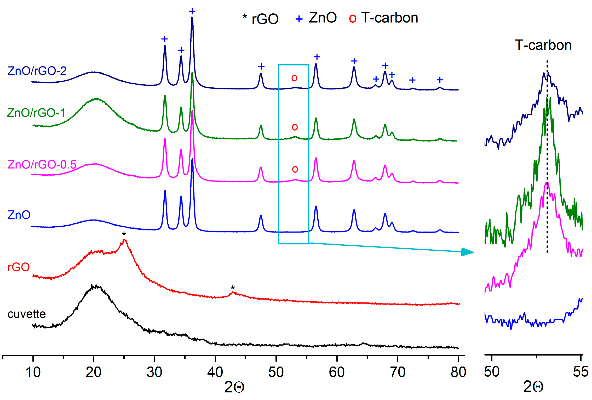
Figure 1. XRD patterns of rGO, ZnO, and ZnO/rGO nanocomposites with different rGO content.
Chemosensors 11 00227 g001
Figure 2. SEM images of ZnO nanofibers (a), rGO (b) and ZnO/rGO nanocomposite (c).
Chemosensors 11 00227 g002
Figure 3. TEM images of ZnO nanofibers (a), rGO (b) and ZnO/rGO nanocomposite (c).
Chemosensors 11 00227 g003
Figure 4. FTIR spectra of rGO, ZnO nanofibers, and ZnO/rGO nanocomposites.
Chemosensors 11 00227 g004
Figure 5. XP-spectra in C1s (ac) and O1s (df) regions of rGO nanosheets (a,d), ZnO nanofibers (b,e) and ZnO/rGO-1 nanocomposite (c,f).
Chemosensors 11 00227 g005
Figure 6. Dynamic change in sensors’ resistance with periodic changes in the gas phase composition when detecting 1 ppm NO2 in dry air in the temperature range of 150–25 °C under UV illumination.
Chemosensors 11 00227 g006
Figure 7. Sensor signal of ZnO nanofibers and ZnO/rGO composites when detecting reducing gases CO, NH3, H2 and oxidizing gases NO and NO2 in dark conditions (a,b) and under constant UV illumination (c,d) at T = 25 °C (a,c) and T = 150 °C (b,d).
Chemosensors 11 00227 g007
Figure 8. Temperature dependences of the resistance of ZnO nanofibers and ZnO/rGO composites: (a) In dark conditions; (b) Under constant UV illumination (365 nm). (c) Temperature dependences of Rdark/RUV ratio.
Chemosensors 11 00227 g008
Figure 9. Scheme of ZnO band bending and ZnO/rGO heterojunction depending on temperature and UV illumination.
Chemosensors 11 00227 g009
Figure 10. Sensor response of ZnO and ZnO/rGO composites when detecting 1 ppm NO2 in dark conditions and under UV illumination at 25 °C (a) and 150 °C (b).
Chemosensors 11 00227 g010
Figure 11. Sensor response of ZnO and ZnO/rGO composites when detecting 4 ppm NO in dark conditions and under UV illumination at 25 °C (a) and 150 °C (b).
Chemosensors 11 00227 g011
Table 1. Sensor response of various materials when detecting NO2 under UV photoactivation.
MaterialNO2 Concentration, ppmSensor Response,
S = 100% × (Rgas − Rair)/Rair
Ref.
In2O35900[24]
In2O3817,900[25]
SnO2101000[26]
Pd/SnO25180,000[27]
Au/SnO256400[28]
SnO2/rGO10120[29]
WO3511,300[30]
ZnO1708[31]
ZnO1610[32]
ZnO1304[33]
ZnO18820[34]
ZnO0.05157[35]
ZnO(Mg)5100[36]
ZnO(Dy)0.365[37]
Ag/ZnO598[38]
Au/ZnO5.0455[39]
In2O3/ZnO0.53170[40]
ZnO/SnO20.5126,600[41]
ZnO/SnO20.05220[42]
ZnO/In2O35221[43]
ZnO/In2O30.711,600[44]
ZnO/rGO503431[16]
ZnO/CMK-35191[45]
ZnO/MoS20.2188[46]
MoS2/ZnO0.52310[47]
ZnS/ZnO1.0339[48]
Bi2O3/ZnO1.0227[49]
Al/TiO2/Al2O3/p-Si2011.5[50]
CuO/ZnS5.0955[51]
Au/MoS22.530[52]
Graphene10027.5[53]
Disclaimer/Publisher’s Note: The statements, opinions and data contained in all publications are solely those of the individual author(s) and contributor(s) and not of MDPI and/or the editor(s). MDPI and/or the editor(s) disclaim responsibility for any injury to people or property resulting from any ideas, methods, instructions or products referred to in the content.