Abstract
As a new type of composite bridge, the dynamic structural characteristics of a tensioned string bridge need to be deeply studied. In this paper, based on the structural characteristics of a tensioned string bridge, the Rayleigh method is used to derive formulas for calculating the frequencies of vertical, antisymmetric and lateral bending vibrations. The characteristics of the vertical and lateral bending vibration frequencies are summarized. The fundamental frequencies of the antisymmetric vertical bending and lateral bending of the tensioned string bridge are the same as that of the single-span beam under the corresponding constraint conditions. The shape and physical characteristics of the main cable have no effect on the frequency. The vertical bending symmetrical vibration frequency of the tensioned string bridge is greater than the corresponding symmetrical vibration frequency of the simply supported beam. The shape and physical characteristics of the main cable have a greater impact on the vertical bending symmetrical vibration frequency than the lateral bending frequency, and the vertical bending symmetrical vibration frequency increases with an increasing rise-to-span ratio. The tension force of the main cable has no influence on the frequency of tensioned string bridges. The first-order frequency of the tensioned string bridge is generally the vertical bending symmetrical vibration frequency. By adopting a tensioned string bridge structure, the fundamental frequency of a structure can be greatly increased, thereby increasing the overall rigidity of the structure. Finally, an engineering example is applied with the finite element parameter analysis method to study the vibration frequency characteristics of the tensioned string bridge, which verifies the correctness of the formula derived in this paper. The finite element analysis results show that the errors between the derived formula in this paper and the finite element calculation results are less than 2%, indicating that the formula derived in this paper has high calculation accuracy and can meet the calculation accuracy requirements of engineering applications.
1. Introduction
As a newly developed beam and cable combination structure system, beam string structures have been investigated during the past 20 years. Studies show that the beam string structure is especially suitable for large-span spatial structures [,,,,,,]. The beam string structure is mainly applied in large span industrial and architecture structures such as the roof structures of stadiums, convention and exhibition centers, terminal buildings and platform canopies [,,,]. However, it is rarely used in bridge structures. In recent years, due to the unique advantages of the string beam structure in urban construction, this new structural system has been adopted in the design of urban pedestrian bridges.
Since cables are engineering structures, typically with nonlinear characteristics, researchers have paid much attention to the study of both their vibration frequencies and their nonlinear mechanical behaviors. Irvine and Caughey [] established the vibration theory of cables with a small sag. Based on the cable vibration equation and geometric deformation compatibility conditions, they derived the famous horizontal suspension cable frequency equation of in-plane vibration, which plays an important role in the cable vibration theory. Subsequently, Irvine [] extended the horizontal cable vibration theory to inclined cables with a small sag. Triantafyllou et al. [,] derived a more accurate solution with the assumption of the spatial variability of the power cable and consideration of the influence of the weight component parallel to the cable. Li Guoqiang et al. [] found that when the second-order term is considered in the deformation compatibility equation, the free vibration of the cable exhibits nonlinear characteristics. Larsen et al. [] studied the dynamic characteristics of a three-span continuous suspension bridge without considering the stiffness of the pylons and derived estimation formulas for the fundamental frequency of symmetric vertical bending and torsion. In Li et al.’s research [], it was concluded that such cable structures themselves have rich nonlinear dynamic characteristics for suspension bridges, including cable-stayed bridges. However, whether and how to consider these nonlinear dynamics in engineering practice should be further investigated. Therefore, as a special kind of nonlinear cable structure, the vibration frequency calculation formula and structural vibration frequency characteristics of a tensioned string bridge structure need to be studied in depth.
The analysis of structural dynamic characteristics is an important part of the design and calculation of bridge structures. The approximate calculation of the natural frequency of engineering structures is also a topic that has received attention from many researchers []. Low [,] used an eigenanalysis and Rayleigh’s estimation to analyze the frequency characteristics of a beam carrying multiple point masses at various locations and verified that the Rayleigh method can provide a better approximation, which can replace the solution of the complex eigenfrequency equation. H.R. Öz [] studied the natural frequency of a Euler–Bernoulli-type beam with a certain mass by using the finite element analysis method and compared it with other methods, such as the Rayleigh method. Valle et al. [] proposed a new closed-form equation for beams subjected to axial loads. This equation can very accurately simulate the relationship between the natural frequency of an axially stressed beam and the axial load under different end conditions. Yang et al. [] conducted elastic and plastic experimental studies on the first natural frequency of fixed-supported steel beams under different axial tensile loads and discussed the influence of plasticity on the natural frequency of the structure. The current Chinese Bridge Wind Design Code [] also gives the basic frequency estimation formulas for cable-stayed bridges and suspension bridges. In recent years, studies on the dynamic characteristics of tensioned string structures have been conducted considering engineering examples and applications. Based on the parameter analysis method, Wang Xiuli et al. [] determined the natural vibration law and the influence of the rise-span ratio, vertical-span ratio, number of struts and other parameters on the natural vibration characteristics of a string beam structure. He Yongjun et al. [] analyzed the order of appearance of the first-order vibration modes and the corresponding natural vibration period of a tensioned giant grid structure. The change pattern of stiffness of the structure in various directions with different parameters was studied in detail as well. In Chen’s [] research, the Galerkin method was applied to obtain the analytical solution of an arched string structure. The results were compared with the model test and nonlinear finite element analysis results, verifying the accuracy of the proposed theoretical formula. Jiang [] established a nonlinear dynamic finite element model of a long-span string beam structure based on engineering examples, analyzed the natural vibration characteristics of the string beam structure and discussed the distribution laws of various frequencies and corresponding modes. Based on parameter analysis methods, Shi [] investigated the influence of prestress, number of struts, cable cross-sectional area and restraint conditions on the natural vibration characteristics of long-span string truss structures. The results show that the low-order mode of the tensioned truss structure is dominated by vertical vibration; the low-order mode vibration can rarely be affected by the cross-sectional area of the cable, but is significantly influenced by constraint conditions.
Previous studies have mainly focused on the spatial string beam structure with parameter analysis and dynamic finite element methods. However, a tensioned string bridge is a typical long structure, which is quite different from the large-span spatial string structure, and no relevant research has been conducted on its fundamental frequency calculation and frequency characteristics thus far. In this paper, based on the existing literature [], the Rayleigh method is applied to study the simplified calculation formula of the fundamental frequency of a tensioned string bridge, and the corresponding frequency characteristics are analyzed to provide a preliminary design calculation basis for the dynamic calculation of a tensioned string bridge.
2. Rayleigh’s Method of Frequency Calculation
The basic principle of applying the Rayleigh method to calculate the vibration frequency of a structure is based on the theory that when an undamped elastic system vibrates freely, its total energy remains unchanged at any time point. When the velocity is zero, the strain energy of the structure reaches the maximum, and when the structural strain energy is zero, the structural kinetic energy is maximum; therefore:
where is the maximum kinetic energy when the strain energy of the system is zero and is the maximum strain energy when the kinetic energy of the system is zero.
Taking the free vibration of a typical distributed mass beam with equal cross-section as an example, the vibration displacement at any time can be expressed as:
where is the displacement amplitude, is the natural frequency, and is the initial phase angle.
Then, the maximum bending strain energy of the beam is derived as:
where is the bending stiffness of the beam and is the length of the beam.
The maximum kinetic energy of the beam is as follows:
where is the mass per unit length of the beam. From Equation (1), the frequency of the beam can be obtained as:
As long as the structural mode shape function can be approximately determined, the frequency corresponding to the mode shape can be obtained from Equation (5).
3. Structural Characteristics of the Tensioned String Bridge and Compatibility Equation of the Main Cable Geometric Deformation
3.1. Characteristics of the Tensioned String Bridge
The tensioned string bridge is composed of three types of basic components: the upper rigid main girder that bears compression and bending, the lower string (main cable) that bears tensile force and the compression brace strut connecting these two components. Simple support constraints are applied on the tensioned string bridge. By prestressing the lower chord cable, the whole structure is a typical prestressed self-balancing structure system. A sketch of the tensioned string bridge is shown in Figure 1. For tensioned string bridges, the main girder of the tensioned string bridge is subjected to a greater pressure, and the rigidity of the main girder of the tensioned string bridge is relatively large, which is different from suspension bridges. Therefore, the shape of the main cable is generally designed as a secondary parabola or catenary with a rise-to-span ratio of approximately 1/10.
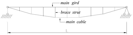
Figure 1.
Structural characteristics of the tensioned string bridge.
3.2. Geometric Deformation Compatibility Equation of the Main Cable of the Tensioned String Bridge
A microsection is selected to derive the geometric deformation compatibility equation of the main cable of the tensioned string bridge, as shown in Figure 2. Due to vibration, the position is changed from the initial position AB to the final position with the change in length from to ds. , and are the horizontal, vertical and lateral displacements of the main cable, respectively.
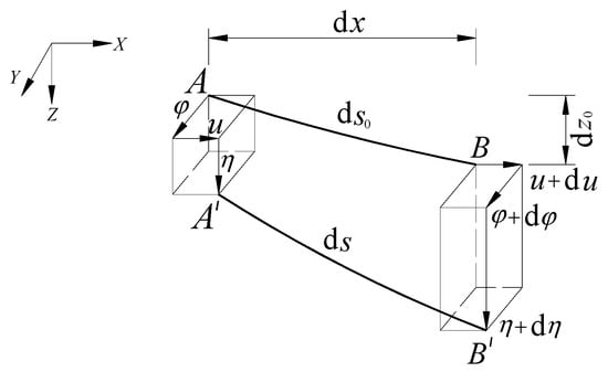
Figure 2.
Microstructure of the main cable.
According to the displacement geometric relationship shown in Figure 2, the elongation per unit cable length can be obtained as:
The relationship between the main cable force and displacement can be written as:
where is the increment of tension caused by the main cable vibration and and are the elastic modulus and cross-sectional area of the main cable, respectively. Considering the horizontal force of , the increase in the horizontal force component of the main cable due to vibration can be written as:
Substituting Equations(7) and(8) into Equation (6), the following can be obtained:
Integrating the total length of the bridge on the left and right sides of Equation (9), the following equation can be obtained:
Since the horizontal force component increment is constant along the bridge span, the following is obtained:
Due to the structural characteristics of the tensioned string bridge, the horizontal tension increment of the main cable is the same as the pressure on the main beam, and the relative horizontal displacement of the tensioned string bridge at the two fulcrums is the same. The relative horizontal displacement of the main beam and the main cable at the two fulcrums can be written as:
where and are the elastic modulus and cross-sectional area of the main cable, respectively.
The geometric deformation compatibility equation of the main cable can be derived from Equations(11)–(13) as:
Neglecting the high-order terms, Equation (14) can be simplified as:
4. Basic Assumptions for the Frequency Calculation and System Energy of Tensioned String Bridges
The determination of the vibration frequency of the tensioned string bridge is based on the following assumptions:
- (1).
- The main cable is completely flexible, and the stress–strain relationship satisfies Hooke’s law;
- (2).
- The struts are not elongated, and the deformation of the stiffening beam and the main cable are coordinated when vibrating;
- (3).
- Axial shortening of the main beam due to flexural deformation is ignored;
- (4).
- The main cable shape is a secondary parabola under dead loads.
According to the deformation characteristics of the main cable, the strain energy of the main cable can be obtained as:
where Hg is the horizontal component of the self-reconfigurable tensile force of the main cable.
According to assumption (4), the shape of the main cable is a secondary parabola, which can be obtained as:
where f is the rise of the tensioned string bridge.
According to the deformation compatibility Equations in (14) and (17), the following can be obtained:
Ignoring the higher-order terms, the strain energy of the main cable is as follows:
The strain energy of the main beam is as follows:
where and are the vertical and lateral bending moments of inertia of the main beam section, respectively.
With the assumption that struts are not deformed, the strain energy of the struts is 0. Combining Equations (19) and (20), the total strain energy of the cable and beam can be obtained as:
The deflection kinetic energy of the main beam is as follows:
The deflection kinetic energy of the main cable is as follows:
The deflection kinetic energy of the strut is as follows:
Then, the total kinetic energy of the tensioned string bridge structure can be obtained as:
where , and are the unit masses of the main beam, main cable and struts, respectively, and is the total mass per unit length of the tensioned string bridge.
5. Fundamental Frequency Formula of Vertical and Lateral Bending Vibration
5.1. Vertical Bending Antisymmetric Vibration Frequency
When the suspension bridge vibrates in the vertical plane, the horizontal vibration displacement of the main girder and the cable is zero, that is, .
Since the tensioned string bridge is an external simply supported constrained structure in the vertical plane, for the vertical antisymmetric mode, the mode function can be taken as:
For the antisymmetric mode, . Then, the total strain energy of the structure can be obtained from Equation (21) as:
Substituting the mode function into Equation (25), the total kinetic energy of the structure can be obtained as:
From Equation (1), the frequency of the vertical antisymmetric mode can be obtained as:
Formula (31) shows that its frequency is the same as the vibration frequency of a simply supported beam and has no relation with the pretension of the main cable or the physical characteristics.
5.2. Positive Symmetrical Vibration Frequency of Vertical Bending
According to the constraint conditions of the structural support and its deformation characteristics, the mode function of the vertical positive symmetric mode can be taken as:
For the positive symmetrical mode, the horizontal force increment h is not zero at this time; therefore, it can be obtained from Equation (15) as:
For the secondary parabolic main cable:
The following can be obtained from Equation (21):
From Equation (1), the vertical symmetrical mode frequency can be obtained as:
The theoretical solution for the symmetrical frequency of the vertical bending of the simply supported beam is as follows:
Equations (40) and (41) show that the vertical bending symmetrical vibration frequency of the tensioned string bridge is greater than the symmetrical vibration frequency of the corresponding simply supported beam, which is due to the increase in structural rigidity under uniform load mode.
5.3. Fundamental Frequency of Lateral Bending Vibration
When the suspension bridge vibrates horizontally, the vertical vibration displacement of the main girder and main cable is zero, that is, .
Based on the layout of the beam tensioned string bridge support, the constraint condition of its lateral vibration can be approximated as a single-span beam with one end fixed and one orientation support. Therefore, its mode function can be assumed to be the displacement curve under a uniform load under the approximated constraint condition. The constraint condition and its mode shape curve are shown in Figure 3.
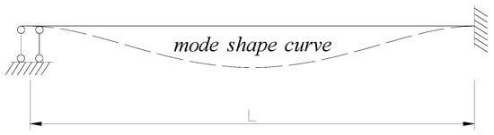
Figure 3.
Restraint condition of lateral vibration.
The mode function of lateral vibration can be written as:
The following can be obtained from Equation (21):
From Equation (1), the vertical symmetrical mode frequency can be obtained as:
Equation (47) shows that the transverse vibration frequency is the same as the exact solution of the vibration frequency of a single-span beam fixed at both ends, and the transverse vibration frequency has no relation with the pretension and physical characteristics of the main cable.
5.4. Characteristics of the Frequency for Vertical Bending and Lateral Bending of Tensioned String Bridges
Based on the derivation of the vertical bending frequency and lateral bending frequency, the following can be concluded:
- (1).
- The vertical bending antisymmetric frequency and lateral bending fundamental frequency of the tensioned string bridge are the same as those of the single-span beam under the corresponding constraint conditions. The shape and physical characteristics of the main cable have no effect on the frequency.
- (2).
- The vertical bending symmetrical vibration frequency of the tensioned string bridge is greater than the symmetrical vibration frequency of the corresponding simply supported beam. The shape and physical characteristics of the main cable have a significant impact on the vertical bending symmetrical vibration frequency.
- (3).
- The vibration frequency of the tensioned string bridge has nothing to do with the pretension of the main cable, which is different from usual suspension bridges. This agrees with the conclusion of reference [] in regard to the static force characteristics of tensioned string bridges. For a normal suspension bridge, one of the most important features is that the main cable tension provides strong gravity stiffness. The vertical stiffness of the suspension bridge structure is closely related to the main cable tension force.
6. Verification by Engineering Application
An example of a pedestrian tension bridge with a calculated span of 55 and a rise-to-span ratio of 1/11 is presented. The main girder is a flat steel box structure with a girder height of 0.8 and a bridge deck width of 3. The main cable is a single high vanadium cable with a basic linear catenary design that is designed with 9 V-shaped braces and 5.5 center spacing of the braces. With the application of the finite element analysis software ANSYS, the bridge is simulated as a spatial dynamic finite element model. The main beams and struts are simulated by BEAM4 spatial beam elements, and the main cable is simulated by LINK10 nonlinear cable elements. The prestress of the main cable is considered when modeling structural rigidity. The established finite element model is shown in Figure 4, and the analyzed first 3 modes are shown in Figure 5, Figure 6 and Figure 7. The main parameters are as follows:
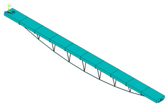
Figure 4.
Dynamic finite element model.
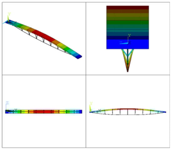
Figure 5.
Symmetrical mode of vertical bending ().
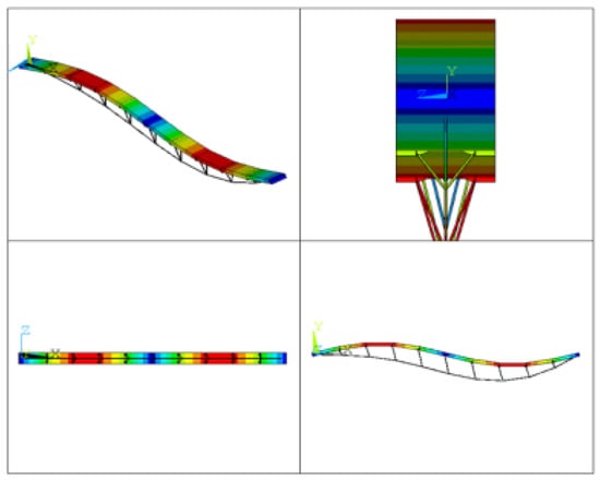
Figure 6.
Antisymmetrical mode of vertical bending ().
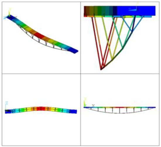
Figure 7.
Lateral bending mode ().
Table 1 shows that the error between the derived analytical solution and the finite element calculation result is less than 2%, indicating that the derived analytical solution result has a high accuracy, and the analytical solution is larger than the finite element result, which is mainly because when the actual vibration curve is replaced by the assumed vibration curve, it is equivalent to imposing certain constraints on the system, thereby increasing the rigidity of the system and resulting in an increase in frequency.

Table 1.
Fundamental frequency calculated by the proposed method.
The vertical bending symmetrical vibration frequency of the corresponding simply supported beam from Equation (41) is 0.74 Hz, which is much smaller than the vibration frequency of a tensioned string bridge with the same span. The frequency of a tensioned string bridge is 2.2 times higher than that of a simply supported beam with the same span.
Meanwhile, it can be seen from the finite element analysis results of the engineering example that the first mode of the beam tensioned string bridge is generally the vertical bending symmetrical mode due to the greater rigidity of the main girder. Therefore, with the utilization of string beam bridges, the fundamental frequency of the structure can be greatly improved, that is, the overall rigidity of the structure is improved, which has great practical significance for improving the dynamic stability of wind-resistant structures.
7. Analysis of Vibration Frequency Parameters by the Finite Element Method
7.1. Influence of the Pretension of the Main Cable on the Vibration Frequency
Based on the finite element model shown in Figure 3, the influence of the pretension of the main cable on the vibration frequency is studied by adjusting the pretension of the main cable. Three conditions are applied to conduct the parameter analysis, namely, the establishment of three finite element models with 1.0 time, 1.5 times and 2.0 times the main cable force (original bridge model). The comparison of the calculation results of the vibration frequency of each model is shown in Table 2.
Table 2.
Frequency calculation of the main cable force variation (Hz).
From the calculation results in Table 2, it can be seen that the frequencies of the symmetrical vertical bending, antisymmetric vertical bending and lateral bending modes are identical. The main cable force has essentially no effect on the calculation results of each vibration frequency. The finite element parameter analysis results are consistent with the formulas derived in this paper, which verifies their correctness.
7.2. Influence of the Rise-Span Ratio on the Vibration Frequency
To study the effect of the rise-span ratio on the vibration frequency, the finite element model shown in Figure 3 is also applied. With the other parameters unchanged, the rises are set as 4 m (the original bridge model), 5 m and 6 m. The corresponding rise-span ratios are 1/13.75, 1/11 and 1/9.17. The comparison of the calculation results of the vibration frequency of each model is shown in Table 3.
Table 3.
Frequency calculation of the rise-to-span ratio variation(Hz).
From the calculation results in Table 3, it can be seen that the symmetrical vibration frequency of vertical bending significantly increases with increasing rise-to-span ratio. When the rise increases from 4 m to 6 m, the vertical bending symmetric frequency increases from 1.3941 Hz to 1.8567 Hz, with an increase of 33%. However, the frequencies of the antisymmetric and lateral vertical bending modes are unchanged with the rise-to-span ratio, and it can be concluded that the change in the main cable force has no influence on the frequency; that is, the shape and physical characteristics of the main cable have no effect on it. The above analysis shows that the finite element parameter analysis results are consistent with the formulas derived in this paper, verifying the accuracy of the derivation.
The analysis of the above parameters shows that changing the rise-span ratio and the main cable force provides a design idea for adjusting the basic frequency and structural rigidity of a tensioned string bridge.
8. Conclusions
In this research, by studying the nonlinear mechanical characteristics of tensioned string bridges, based on theoretical derivation and parameter analysis of engineering examples, a number of conclusions are obtained.
According to the structural characteristics of the tensioned string bridge, based on the Rayleigh method, the fundamental frequency calculation formulas of the vertical bending symmetric, vertical bending antisymmetric and lateral bending vibrations of the tensioned string bridge are derived, and the main characteristics of the frequency calculation equation of the tensioned string bridge are summarized.
Based on the finite element parameter analysis of an engineering example, the analysis results show that the main cable force has no influence on the vibration frequency. The symmetrical vibration frequency of vertical bending increases with the increase of the rise-span ratio, while the vibration frequency of the vertical bending antisymmetric and lateral bending modes has no relation with the rise-span ratio, which agrees with the calculation results based on the derived equation.
The errors between the calculation results based on the derived formula and the finite element analysis results are less than 2%, indicating that the calculation results from the formula have a high calculation accuracy and can meet the requirements of engineering applications.
Due to the greater rigidity of the main beam, the first mode of the tensioned string bridge is generally a vertical bending symmetrical mode. Therefore, with the utilization of a tensioned string structure, the fundamental frequency of the structure can be greatly improved, that is, the overall rigidity of the structure is improved, which is of great significance for improving the dynamic stability of wind-resistant structures of tensioned string bridges.
Author Contributions
Author Contributions: Conceptualization, G.Z.; formal analysis, G.Z. and C.Q.; investigation, G.Z. and C.Q.; writing—original draft preparation, G.Z.; writing—review and editing, G.Z. and C.Q.; supervision, C.C.; funding acquisition, G.Z., C.Q. and C.C. All authors have read and agreed to the published version of the manuscript.
Funding
This work received no external funding.
Institutional Review Board Statement
Not applicable.
Informed Consent Statement
Not applicable.
Data Availability Statement
Not applicable.
Acknowledgments
This research is supported by the Fujian Science and Technology Project (Guiding Project) (Grant Number: 2021Y0042), the National Natural Science Foundation of China (Grant Number:52178510) and the National Key R&D Program of China (Grant Number: 2017YFC0806000).
Conflicts of Interest
The authors declare no conflict of interest.
References
- Shen, S.-Z.; Xu, C.-B.; Zhao, C.; Wu, Y. Suspension Structure Design, 2nd ed.; China Construction Industry Press: Beijing, China, 2006. [Google Scholar]
- Guo, Y.-L.; Tian, G.-Y. Cable Structure System, Design Principle and Construction Control; Science Press: Beijing, China, 2014. [Google Scholar]
- Zhao, X.-Z.; Chen, J.-X.; Chen, Y.-Y. Experimental Study on Structural Performance during Prestressing of Beam String Structure. J. Build. Struct. 2007, 28, 1–7. [Google Scholar]
- Jiang, Y.-B.; Huang, X.-X. Stiffness Parametric Analysis and Design Optimization on Stiffness of Beam String Structure. J. Guangxi Univ. (Nat. Sci. Ed.) 2015, 40, 798–805. [Google Scholar]
- Li, J.-B.; Hong, C.-L.; Zhang, Z.; Li, S.-J. The Inquiry of Tension Method for the Beam String Structure. J. Zhengzhou Univ. (Eng. Sci.) 2015, 36, 61–65. [Google Scholar]
- Fan, D.-H.; Yong, D.; Shen, H.-M. Mathematical Calculations for the Characteristics of Beam String Structure in Fire. Eng. Mech. 2016, 33, 195–204. [Google Scholar]
- Yin, Z.; Xu, Y. Study of the Bidirectional Beam String Structure Test of Cable Tension Based on Half-wave Method. Chin. J. Appl. Mech. 2018, 35, 880–885. [Google Scholar]
- Wang, D.-S.; Zhang, F.-L.; Gao, C.-Y.; Zhou, J.; Chen, H.-Y. Research and Design of Steel Structure of Shanghai Pudong International Airport Terminal (First Phase of the Project). J. Build. Struct. 1999, 20, 2–8. [Google Scholar]
- Ding, J.-M.; He, Z.-J. Several Key Issues of Structural Analysis of Prestressed Steel Truss Shells Roof of Beijing University Gymnasium. J. Build. Struct. 2006, 27, 44–50. [Google Scholar]
- Zhang, Z.; Ding, J.; Li, L. Structural system selection and design for large-span concave steel roof of Changsha International Convention and Exhibition Center Hall. Build. Struct. 2020, 50, 67–73. [Google Scholar]
- He, J. Research on the Canopy Design and Construction Technology of Platform with Beam String in Yinchuan Station. J. Railw. Eng. Soc. 2020, 259, 74–78. [Google Scholar]
- Irvine, H.M.; Caughey, T.K. The linear theory of free vibrations of a suspended cable. In Proceedings of the Royal Society of London Series A; Royal Society: London, UK, 1974; Volume 341, pp. 299–315. [Google Scholar]
- Irvine, H.M. Free vibration of inclined cables. Journal of the Structural Division. In Proceedings of the American Society of Civil Engineers; American Society of Civil Engineers: New York, NY, USA, 1977; Volume 104, pp. 343–347. [Google Scholar]
- Triantafyllou, M.S. The dynamics of taut inclined cables. Q. J. Mech. Appl. Math. 1984, 37 Pt 3, 421–440. [Google Scholar] [CrossRef]
- Triantafyllou, M.S.; Grinfogel, L. Natural frequencies and modes of inclined cables. J. Struct. Eng. ASCE 1986, 112, 139–148. [Google Scholar] [CrossRef]
- Guoqiang, L.; Ming, G.; Limin, S. Theory of Cable Vibration, Dynamic Detection and Vibration Control; Beijing Science Press: Beijing, China, 2014; pp. 16–19. [Google Scholar]
- Larsen, A.; Gimsing, N.J. Wind engineering aspects of the east bridge tender project. J. Wind Eng. Ind. Aerodyn. 1992, 42, 1405–1416. [Google Scholar] [CrossRef]
- Li, L.; Sen, L.; Jinxiang, L. Nonlinear Dynamics and Large-scale Torsional Vibration of Suspension Bridges. J. Highw. Transp. Res. Dev. 2001, 18, 29–31. [Google Scholar]
- Ren, W.X.; Blandford, G.E.; Harik, I.E. Finite-element model and free vibration response. J. Bridge Eng. 2004, 9, 110–118. [Google Scholar] [CrossRef]
- Low, K.H. A further note on closed-form formulas for fundamental vibration frequency of beams under off-centre load. J. Sound Vib. 1997, 207, 132–135. [Google Scholar] [CrossRef]
- Low, K.H. Natural frequencies of a beam–mass system in transverse vibration: Rayleigh estimation versus eigenanalysis solutions. Int. J. Mech. Sci. 2003, 45, 981–993. [Google Scholar] [CrossRef]
- Öz, H.R. Calculation of the Natural Frequencies of a Beam–Mass System Using Finite Element Method. Math. Comput. Appl. 2000, 5, 67–76. [Google Scholar] [CrossRef]
- Valle, J.; Fernández, D.; Madrenas, J. Closed-form equation for natural frequencies of beams under full range of axial loads modeled with a spring-mass system. Int. J. Mech. Sci. 2019, 153, 380–390. [Google Scholar] [CrossRef]
- Yang, T.Y.; Wiebe, R. Experimental Study on the Effect of Large Axial Tensile Force on the Natural Frequency of a Fixed-Fixed Steel Beam. In Nonlinear Dynamics; Springer: Cham, Switzerland, 2017; Volume 1, pp. 127–134. [Google Scholar]
- Ministry of Transportation of the People’s Republic of China. Wind-Resistant Design Specification for Highway Bridges; China Communications Press Co., Ltd.: Beijing, China, 2018; pp. 51–52. (In Chinese) [Google Scholar]
- Wang, X.; Ding, N.; Cui, J. Analysis of free vibration characteristics of stringed beam structure. J. Lanzhou Univ. Technol. 2006, 32, 105–108. [Google Scholar]
- He, Y.; Sun, X.; Zhou, X. Research on dynamic performance of string reticulated mega-structure. J. Disaster Prev. Mitig. Eng. 2016, 36, 737–743. [Google Scholar]
- Chen, N.; Zhao, J. Dynamic behavior study of arch string structure with upward-curved cable. Build. Sci. 2018, 34, 7–14. [Google Scholar]
- Jiang, J.; Feng, J. Study on natural vibration characteristics of long-span beam string structure. Spec. Struct. 2007, 24, 46–47. [Google Scholar]
- Shi, Q.; Cai, Y.; Li, A. Analysis of free vibration characteristics and seismic response of long-span truss string structure. Sichuan Build. Sci. 2012, 38, 154–159. [Google Scholar]
- Zhou, G.; Qian, C. Study on Static Structural Analysis Method and Mechanical Characteristics of String-tensioned Bridge. J. Highw. Transp. Res. Dev. 2020, 37, 63–69. [Google Scholar]
Publisher’s Note: MDPI stays neutral with regard to jurisdictional claims in published maps and institutional affiliations. |
© 2022 by the authors. Licensee MDPI, Basel, Switzerland. This article is an open access article distributed under the terms and conditions of the Creative Commons Attribution (CC BY) license (https://creativecommons.org/licenses/by/4.0/).