1. Introduction
In order to obtain good quality asphalt, completely drying the aggregates is an important process carried out with rotary dryers containing a drum that rotates at certain speeds. The drum is slightly horizontally inclined and is equipped with flights of different shapes and sizes.
In the case of direct rotary dryers, the heat used to dry the aggregates comes from the hot gas supplied by a burner [
1]. The process of drying aggregates involves significant energy consumption as well as negative effects on the environment. In order to decrease the energy consumption and the amount of toxic gas, it is necessary to increase the efficiency of drying aggregates in the drum [
2] by adopting different solutions for the design of dryers. A main advantage is the generation of savings within companies in the field of asphalt mixture production, taking into account that the consumption of energy in the process of drying mineral particles is between 70–100 kWh per ton of mineral aggregates produced, resulting in approximately 22 kg of CO
2 [
3].
Jullien [
4] states that up to 97% of the energy consumed in asphalt production plants is used to dry the aggregates. Therefore, it is very important to find methods to make the drying process more efficient. The performance of flighted rotary dryers is mainly determined by the efficiency of the contact between the particles and the hot gas [
5]. The optimal drum loading and the maximum degree of use of the active area where drying occurs (obtaining a dense curtain of aggregates so that the cross-sectional area of the drum, occupied by the cascading particles, is as large as possible and remains so for as long as possible during its rotation) significantly influences the high performance of aggregate drying.
Many scientific studies [
5,
6,
7,
8,
9,
10,
11,
12,
13,
14,
15,
16,
17,
18,
19,
20,
21,
22,
23] were conducted in order to evaluate the proper configuration of the flights, investigating the influence of flight type [
11,
12,
14,
17,
18], flight dimensions [
5,
8,
9,
10,
16,
22,
23] or the number of flights [
9,
10,
23]. Theoretical and experimental studies have shown that a particular influence on the performance of rotary dryers is the flight configuration, which must be chosen in accordance with the characteristics of dried materials [
5]. Therefore, when drying fibrous or cohesive particles, straight flights are recommended or used because the mixing speed is increased [
24]. In [
25], an experimental study was successfully carried out for drying filamentous particles with a straight-flight configuration for wet-cut tobacco. For free-falling materials, various other flight shapes, such as semi-circular, rectangular, angular, etc. can be used; the two-segment rectangular flights ensure the dispersion of a large number of particles in the hot gas stream.
Numerical simulations have become essential tools for studying different industrial equipment in order to optimize their design and operation. In the case of bulk solids, it is recommended to use the numerical technique based on the Discrete Element Method (DEM). This method was applied by Zhang et al. [
24] to study the movement of plastic particles in the dryer equipped with straight flights, varying various parameters such as the drum rotation speed (10 rpm, 20 rpm, 30 rpm) and its filling degree (10%, 15%, and 20%), noting that an increase in drum rotation speed causes an increase in the retention ratio of the particles in the flights. When the drum rotation speed increases and its degree of filling decreases, there is an increase in the average speed and temperature of the particles. In the same way, Xie et al. [
8] carried out a simulation with DEM to study the effect of the geometrical shape of two-segment straight flights, as well as the drum operating parameters (speed, degree of filling) in order to optimize the dispersion of aluminum ceramic particles. The scientific work carried out by Silveira et al. [
5] is based on the analysis of the dynamics of the glass bead particles inside the rotating drum with straight flights formed by three segments, establishing optimal configurations for the geometric shapes of the flights.
Analyzing the scientific literature, it was noted that there are not many studies conducted on the influence of flight geometry on the degree of dispersion for mineral aggregate particles. The vast majority of DEM research is focused, in particular, on particles with spherical or rounded shapes due to the considerable reduction of the computation time.
The present study, based on numerical analysis with DEM, aims to establish the optimal configuration of rotary dryers for aggregates from the point of view of drying efficiency. Practically, the correlations between the geometrical shape of the flights and the working parameters, such as drum rotation speed and drum filling degree, are determined to obtain the greatest possible efficiency of the drying process, quantified by the degree of dispersion of the particles in the active area of the drum cross-section. The authors used specific techniques based on image analysis to estimate the percent of the area occupied by the particles in the active region of the drum. The performed analyses took into account the angular-sharp shape of the aggregate particle edges. In this way, the results are much closer to reality, simulating the real distribution of the particles on the active area of the drum, during the drying process. Optimum values and combinations of parameters were established and discussed, taking into account the complexity of the fabrication method for different flight configurations. Different geometrical shapes of flights offer advantages specific to the manufacturing technology. For example, the cup-type flight can be made by using a tubular semi-fabricated piece cut on two generators. This avoids cold plastic deformation or, for large thicknesses, hot plastic deformation, processes that are energy-consuming and require special equipment. The results obtained can be useful for further practical engineering applications in the industry of asphalt mixture production, taking into account the current challenges regarding energy consumption.
2. Materials and Methods
The analysis was carried out for a real drying drum—ECO 2000 made by Benninghoven, with the following dimensional characteristics: inside diameter,
Di = 2200 mm, wall thickness,
t = 12 mm, length,
L = 8000 mm, made of S235JR steel with 16 flights evenly distributed on its internal surface (flight length,
Lf = 800 mm) as can be seen in
Figure 1. Due to the necessity to reduce the computation time in DEM analysis, a 1:4 scale model for the real rotary dryer and the flights were used. The geometric model was reproduced in Ansys SpaceClaim, considering for analysis and comparison, different flight shapes presented in
Figure 2.
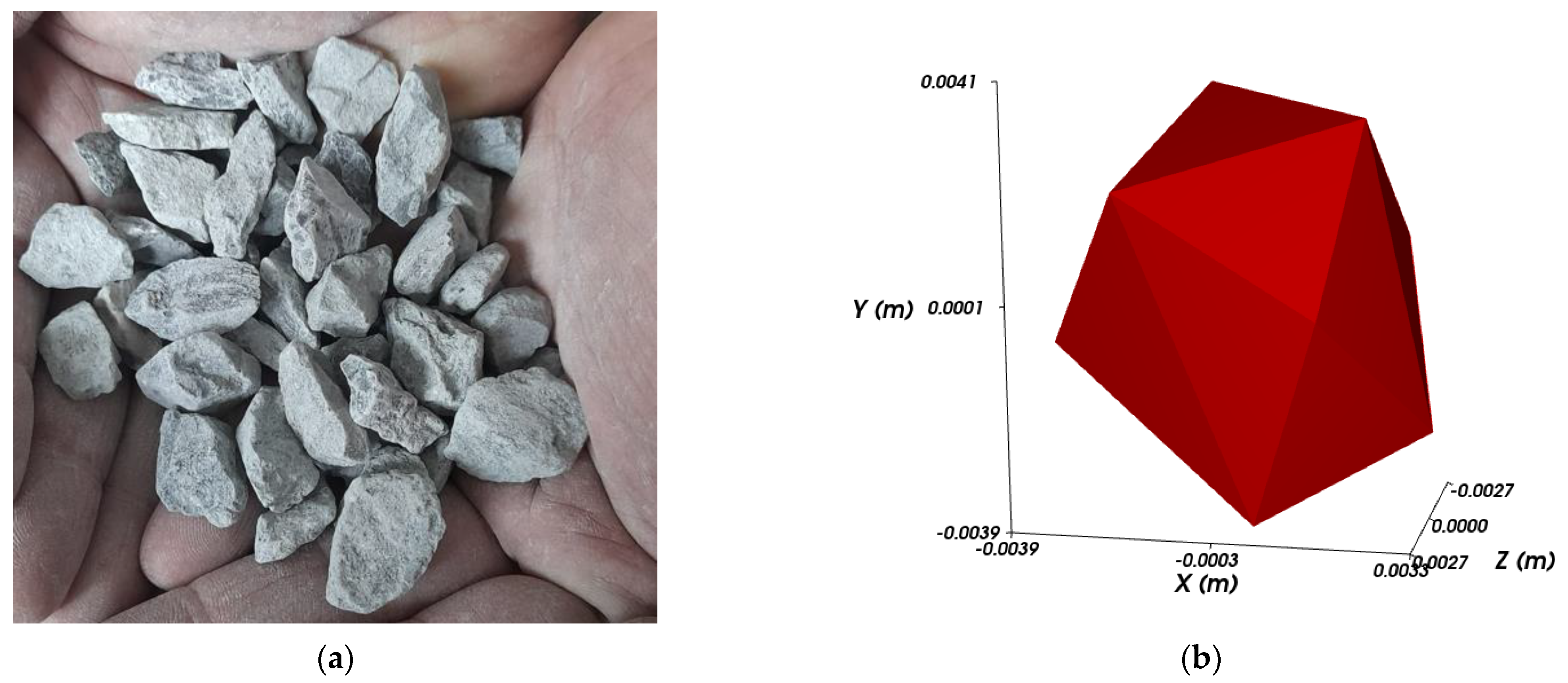
The numerical analysis with DEM was performed with Rocky 2022 R2 software, and the particlesconsidered in the study are crushed mineral aggregates (through mechanical methods—crushing) with complex shapes (
Figure 3). In order to reduce the computational time, the maximum dimension of particles by reference to the three orthogonal directions was considered equal to 8 mm. For a more precise representation of the real model, a polyhedral geometric model with 10 corners was chosen, as seen in
Figure 3b.
The density of the bulk aggregates was determined experimentally by weighing the mass of one liter of aggregates, as in
Figure 4. An average value of 1350 kg/m
3 was obtained for five measurements.
The contact parameters introduced in DEM simulation were chosen according to the indications from [
26,
27,
28]: the static friction coefficient for stone-steel μ
s1 = 0.4, stone-stone μ
s2 = 0.5; the dynamic friction coefficient for stone-steel μ
d1 = 0.4, stone-stone μ
d2 = 0.5; and the restitution coefficient for stone-steel
r1 = 0.5, stone-stone
r2 = 0.3. In [
26], the calibration was performed in order to verify the correctness of the parameters used in the DEM analysis, so the repose angle was determined for the same mineral aggregates as considered in the present work, using the cylinder test with slow lifting velocity. The maximum difference between DEM and experimental results for repose angle was only 5.57%.
Parametric studies were performed, corresponding to the different filling degrees of the drum (10%, 15%, and 20%) and different rotation speeds of the drum (8 rpm, 10 rpm, and 15 rpm). The specified parameters were chosen, taking into account that many studies from the scientific literature showed that drum filling degree and drum rotation speed have a great influence on the rotary dryer’s functioning.
The above-mentioned filling degrees correspond to 4.8 kg, 7.2 kg, and 9.6 kg, respectively, of mineral aggregates. These values were determined based on the dimensional characteristics of the analyzed drum and the size and density of the stones.
The degree of dispersion of the particles in the active area of the drum was determined by calculating the percentage (
AOR) represented by the area occupied by the particles (
AOP), from the total active area (
TAR):
The determination of
AOR was made with the image processing program ImageJ. In the first step, theactive area of the drum wasselected, then the image was converted to 8-bit grayscale (
Figure 5). Therefore, the black pixels correspond to the areas occupied by particles, and the white pixels to the empty areas [
5,
29].
For better accuracy of the obtained results, using the recommendations from [
28], the area occupied by the particles (
AOP) was calculated after excluding thecrowded region (the agglomeration surfaces—
Figure 5) from the bottom area of the drum.
3. Results and Discussion
Taking into account that the first unloading of the particles is made at 9 o’clock and the last unloading takes place at 4 o’clock, the percentages of the area occupied by the particles
(AOR) were calculated for different positions, corresponding to 9 to 4 o’clock (with one-hour incremental steps) and the results are presented in
Table 1,
Table 2,
Table 3 and
Table 4.
The results from
Table 1,
Table 2,
Table 3 and
Table 4 show that the percentage of the area occupied by the particles is maintained at values above 10%:
In the case of L-type flights, in the range 12 o’clock–3 o’clock for 10% filling degree (except for 15 rpm drum rotation speed) and 11 o’clock–4 o’clock for 15% and 20% filling degrees;
in the case of hook-type flights, in the range 11 o’clock–2 o’clock for 10% filling degree and 11 o’clock–3 o’clock for 15% and 20% filling degrees (except for 15% filling degree and 15 rpm drum rotation speed);
in the case of cup-type flights, in the range 12 o’clock–2 o’clock for 10% filling degree and 11 o’clock–4 o’clock for 15% and 20% filling degrees (except for 15% filling degree and 15 rpm drum rotation speed);
in the case of rectangular, double-angled type flights, in the range 11 o’clock–2 o’clock for 10% filling degrees (except for15 rpm) and 10 o’clock–4 o’clock for 15% and 20% filling degrees (except for 15 rpm drum rotation speed).
Similarly, as in [
12], the percentage of the area occupied by the particles had an oscillatory nature during the drum rotation for all of the flight configurations, which means that the efficiency provided by a certain type of flight must be analyzed in correlation with important parameters such as drum filling degree or drum rotation speed.
For exemplification,
Table 5,
Table 6 and
Table 7 show the particle dispersion modes for the four types of analyzed flights at 12 o’clock, corresponding to the maximum unload position.
Analyzing the images presented in
Table 5,
Table 6 and
Table 7, it can be seen that at 10% filling degree and 15 rpm, the particles are concentrated towards the lateral area of the drum, so decreasing the drying efficiency.
At 15% filling degree, there is a uniform distribution of the particles in the active area of the drum, except L-type flights.
At 20% filling degrees, in the bottom area of the drum, a crowded regionappears, especially at 8 rpm, which also reduces the drying efficiency.
The results for the optimal loading of drum dryers from this paper are within the range of 10% to 15% recommended in [
6] andin accordance with the optimal loading of 12.7% from reference [
5].
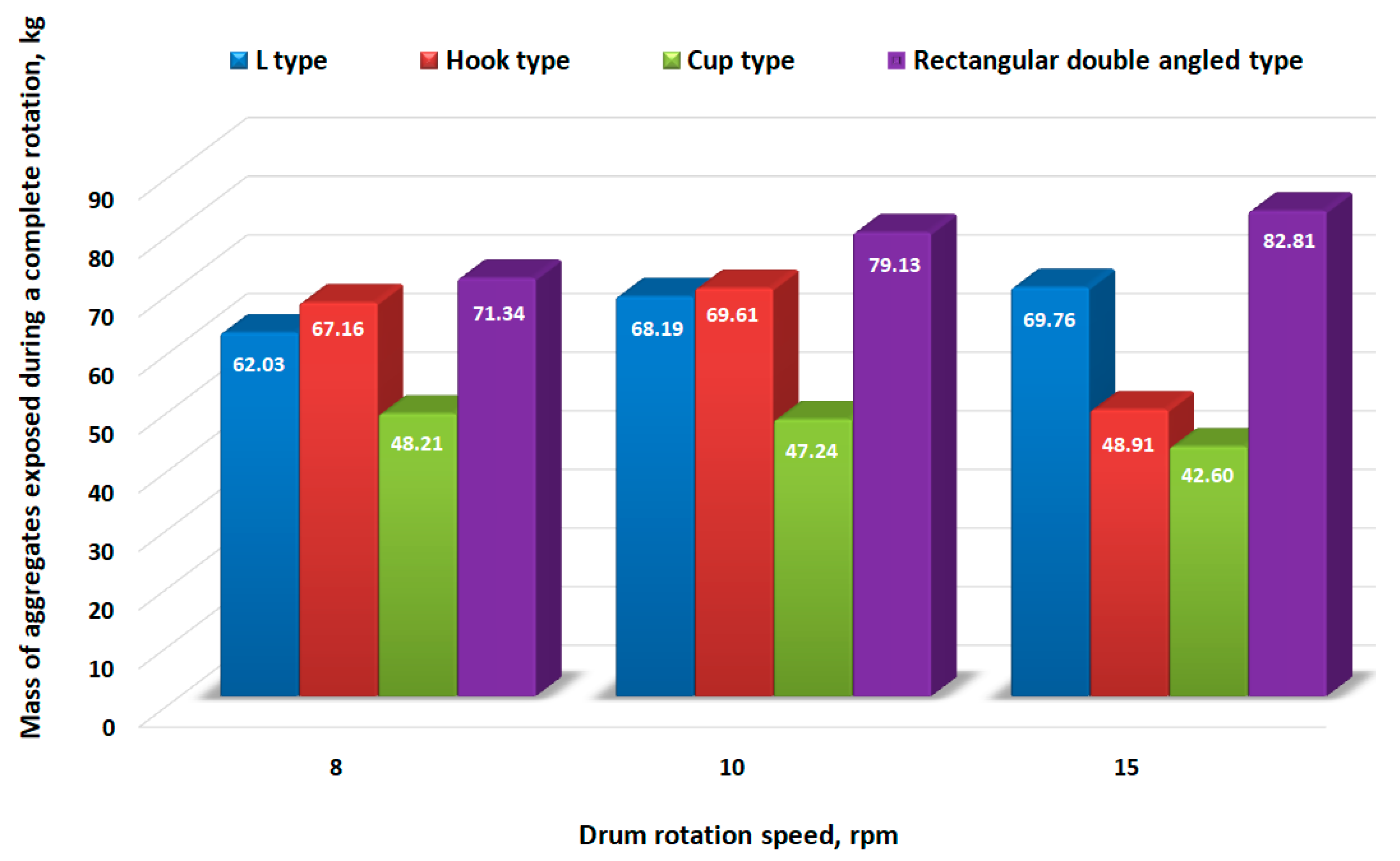
The values of the mass of aggregates exposed to drying during a complete rotation (actually between the 9 o’clock and 4 o’clock positions) are compared in
Figure 6,
Figure 7 and
Figure 8, considering that the particles are uniformly distributed along the length of the drum segment.
Figure 9 and
Figure 10 present a comparison between the mean values of the area occupied by the particles for different filling degrees of the drum and, respectively, for different rotation speeds for different geometrical configurations of the flights.
It can be seen that drum rotation speed does not significantly influence the mass of aggregates exposed to drying at low filling degrees (10%). Thus, an increase of 11.15% in the mass of aggregates exposed to drying when the drum rotation speed increased from 10 rpm to 15 rpm was observed for hook-type flights.
For hook-type flights, at 15% filling degree, when the drum rotation speed increases from 10 rpm to 15 rpm, the mass of aggregates exposed to drying decreases by 42.32%.
At 20% filling degrees, there is a significant increase (41.11%) in the mass of aggregates exposed to drying in the case of rectangular, double-angled type flights.
Therefore, it can be concluded that at low filling degrees (10%), the influence of the drum rotation speed on the drying efficiency is not significant. However, for higher values of filling degree (15% and 20%), it is necessary to take into account the drum rotation speed, the rectangular double-angled type flights having maximum efficiency at 15 rpm. In comparison, in the case of hook-type flights, the minimum value of the mass of aggregates exposed to drying is obtained at 15% filling degree and 15 rpm.
Similarly, the numerical study conducted in [
8] has shown that drum rotation speed has an important role in the particle distribution in the active area of the drum. It was found that in the case of straight flights and 15% drum filling degree, when the rotation speed of the drum increases from 25 rpm to 35 rpm, the percentage of the area occupied by the particles and the mass of aggregates exposed to drying increase. In contrast, for 40 rpm drum rotation speed, the values of these parameters decrease due to the centrifugal force that plays the dominant role in the motion of the particles.
The cup-type flights have the lowest efficiency, justified by the high degree of particle retention during rotation;
L-shaped flights generally have satisfactory performance, comparable to double-angled rectangular flights at low filling degrees (10%) and noticeably lower at 15% and 20% filling degrees, with one exception—at 20% filling degree and 10 rpm rotation speed where the efficiency is similar;
Hook-type flights have similar performances to rectangular double-angled flights, the differences depending on the filling degree. Thus, at 10% filling degree, the results are similar; at 15% filling degree, rectangular double-angled flights have a higher efficiency; at 20% filling degree, the hook-type flights have a higher efficiency, being slightly exceeded only at 15 rpm rotation speed;
Regardless of the filling degree, the hook-type fights show a stable efficiency at rotation speeds of 8 rpm and 10 rpm. Rectangular double-angled flights show a clearly superior performance at high rotation speed (20 rpm).
The filling degree required for optimal loading is strongly influenced by the flight geometry rather than by the operating parameters such as drum rotation speed, so, based on the results obtained, the conclusions of the papers [
30,
31] are confirmed.
4. Conclusions
The present study focused on the numerical analysis using DEM in order to highlight the influence of flight shape on the efficiency of the drying degree for mineral aggregates, assessed by determining the area occupied by the dispersed particles in the active zone of the rotary dryer drum.
Generally, the particles unloading from the flights start when the flight tip is at the 9 o’clock position and it ends around the 4 o’clock position.
Analyzing the obtained values, it was found that, regardless of the flight shape, the maximum efficiency is obtained for the drum rotation speed of 15 rpm, respectively 20% filling degree.
Using the vast amount of obtained data, it was shown that the flight shape significantly influences the degree of dispersion of the particles inside the drum.
The flight shape has an important role in the retention time of the particles on the peripheral area of the drum and, therefore, must be correlated with the rotation speed to identify the optimal solution regarding the particle dispersion. The flight shape should be chosen, also taking into account the drum filling degree, for the same reasons regarding the retention of particles on the flights.
In order to obtain high stability of the values representing the volume of the aggregate exposed to drying during a complete rotation of the drum for a wide range of filling degrees and rotation speeds, the most proper are the hook-type flights. At the same time, the efficiency is high, similar to rectangular double-angled flights.
Even though the rectangular double-angled flights show, on average, the best performance in terms of particle exposure to drying, their performance still presents a wide range in relation to the technological parameters: rotation speed and filling degree.
Compared to other similar research, we have introduced close-to-reality configurations for the aggregate materials that are subjected to drying. In most studies in the scientific literature, the particles are assimilated to spheres and refer, in particular, to cereal seeds, glass, or steel balls. In the present paper, the mineral particles obtained by crushing the stones were studied. The particles have a complex polyhedral shape that certainly affects the constructive integrity of the equipment; this problem will be the subject of a future scientific paper. This complex shape of the particles requires very large computing resources in DEM analysis.
By comparison with the results of other researchers, the trajectories described by the particles are similar (something that confirms the correctness and quality of the model), being dependent in particular on the mass of the particles and the kinematic parameters of the equipment (especially the drum rotation speed). Some differences in the degree of dispersion of the dried particles are generated by the interaction mechanism between the aggregate particles (particle–particle) and between the particles and the flights of the drum, the contacts being linear or on a surface, unlike the sphere model (practiced by most researchers) where the contacts are point-like.


 ,
, 


