1. Introduction
Increasing drilling rate of penetration (ROP) is the primary way to save drilling investment and increase the benefit of oil and gas resource development. However, with long-term, large-scale exploration and development of oil and gas resources, the engineering environment of newly discovered oil fields is very unfriendly to drilling, which makes it increasingly difficult to increase the ROP [
1]. For example, more and more gravel-bearing formations are being drilled, but the economic and time costs of drilling operations in these formations are generally higher due to highly heterogeneous rocks and strong and abrasive gravel particles. Drilling into formations bearing high-strength gravel particles is easy to cause severe vibrations of the bit, including stick–slip and bit bouncing, which then lead to serious damage, fracture, or even collapse of the bit cutters. The working time of a bit is very short, and the trip time will significantly increase. Besides, when drilling into these formations, it is common to weaken the drilling parameters to reduce downhole vibrations, which further restricts ROP improvement. Therefore, it is crucial to study the characteristics and performance of cutting highly heterogeneous gravel-bearing rocks to improve ROP and reduce drilling risks related to vibrations.
Polycrystalline Diamond Compact (PDC) bits have been used in rotary drilling since about the 1900s and have become the most commonly used type of bits in oil and gas drilling [
2]. In China and the United States, more than 85% of the drilled footage in recent years used PDC bits. PDC cutters are in direct contact with formation rocks during drilling, and the study of PDC rock-breaking characteristics has the most direct guiding role in realizing efficient rock breaking. Aiming at the problem of PDC bit rock breaking, researchers have carried out a lot of theoretical and numerical simulation research. In the early research, the relation between the load state of a PDC bit and the rock-breaking volume was examined, aiming to predict the ROP and the wear of the bit [
3,
4,
5,
6,
7]. Warren and Sinor [
8] (1989) proposed a drag-bit performance model to predict the removed volume of rock penetrated by the designed layout of bit cutters. The model predictions compared well to laboratory drilling tests for four radically different bit designs when used on four different rocks. The relationship model between bit force and ROP is widely adopted as the bit boundary conditions in the process of drill-string mechanical modeling [
9,
10]. With the development of computer technology and the demand for rock-breaking enhancement of PDC bits, numerical simulation has become one of the important ways to analyze the rock-breaking performance of the bit. In the beginning, rock-breaking simulations of tools were not included in the cutting behavior, and the focuses were on the process of the tools when invading a rock under a static load. Chiaia [
11] (2001) built a lattice model to discuss the process of indentation of brittle and quasi-brittle materials and pointed out that increasing the size of the indenters improves the local fracture mechanisms. The number of indenters also has a significant effect on the rock-breaking process and the generation of cracks in the rock. Simultaneous loading of multiple indenters with an appropriate line spacing seems to provide a possibility of forming larger rock chips, controlling the direction of subsurface cracks, and consuming a minimum total specific energy [
12]. Later, the rock-breaking behavior of PDC cutters was studied by using the finite element method (FEM) and discrete element method (DEM). The effects of rock type and material model on PDC cutting force and cutting depth were studied to verify the simulation method and obtain reliable modeling parameters [
13,
14,
15,
16]. Jaime [
17,
18] (2011) employed LS-DYNA to simulate the rock-cutting process of PDC cutters; introduced the modeling method, material model selection, and parameter modification process in detail; and analyzed the sensitivity of rock-breaking behavior to loading parameters and material parameters. In addition, the effects of cutter velocity, friction coefficient, and rake angle on rock cutting were investigated to explore the rock-breaking mechanism of the bit and to optimize the bit design [
19]. These simulations demonstrated the importance of the explicit finite element model for simulating the rock cutting and fragmentation process.
With the development of bit machining and design technology, the techniques of percussion drilling and non-plane cutter bit are widely used at present, and corresponding numerical simulation methods have been explored. In addition, the temperature and pressure of a wellbore have a significant influence on rock failure [
20,
21,
22]. Therefore, various factors, such as bottom hole pressure and temperature influencing rock-breaking performance, are considered [
23]. Guarin et al. [
24] (1949) introduced the first case, in the oil field history, of rotary drilling with an impact tool that accomplished extended intervals of formation for sustained periods of time. Melamed et al. [
25] summarized several early percussion drilling tools. Subsequently, numerous studies and experiments were conducted to explore impact drilling techniques. The effects of cutter geometry parameters, cutting angle, impact load, and cutting speed on crack propagation, debris formation, and damage evolution of rock were extensively studied [
26,
27]. Xiong et al. [
28] (2021) investigated mixed tool cutting of granite with stinger PDC cutters and conventional PDC cutters, and they pointed out that the hybrid PDC bits that combine conventional and stinger PDC cutters have significant advantages in drilling hard, interbedded, and highly abrasive rocks. Dong and Chen [
29] (2018) conducted a 3D full-scale PDC bit model to study the dynamic damage characteristics of anisotropic shale during impact rotary drilling. The aim of these studies is to explore the mechanism of PDC cutting rock under an axial impact load or a torque impact load and find realistic ways to improve the efficiency of rock drilling [
30]. In recent years, improving the rock-breaking efficiency of PDC bits and reducing bit vibrations have been considered equally important in dealing with complex downhole drilling conditions [
31,
32]. Additionally, a compound impact load is considered to be an effective method to achieve this goal [
33].
The heterogeneity of rock is one of the main causes of bit vibration and significantly impacts the strength and fracture characteristics of rock [
34]. Therefore, it is necessary to consider the heterogeneity of rock when simulating rock cutting under a compound impact load [
34]. The possibility of simulating heterogeneous rock failure using the finite element method (FEM) or the discrete element method (DEM) has been confirmed [
35]. It is more convenient to establish a DEM heterogeneous model by changing the bond strength between the contact particles [
36]. However, in the aforementioned studies of rock-breaking mechanisms, the investigation of gravel-bearing rock, which has stronger heterogeneity caused by the huge strength difference between the matrix and the gravel broken by a PDC cutter, under a compound impact load is still in the exploratory stage. Furthermore, the simulation method using a constant boundary of bit loading or cutting depth to characterize such cutters has obvious defects. The stick–slip phenomenon and continuous cutting in the process of rock breaking cannot be simulated at the same time.
In this paper, a heterogeneous rock modeling method based on the discrete element theory is proposed. In this method, a random polygonal aggregate is used to characterize the gravel particles inside the rock. The fracture characteristics of a PDC cutting heterogeneous gravel-bearing rock under the action of a compound impact load are simulated and studied. On this basis, field tests to reduce the rock-breaking vibration of gravel-bearing formation with a composite impactor are carried out. The method and conclusions of this paper provide theoretical basis and technical reference for ROP improvement and safe drilling in gravel-bearing formations.
2. Simulation Method
The DEM was first introduced into rock mechanics by Cundall, and a particle assembly program based on the DEM was proposed in 1979 [
37]. It is based on the idea that the object researched is composed of a certain number of arbitrary particles or particle clusters with mass and volume in the particle assembly procedure. The particles are specified as disks with unit thickness in the two-dimensional (2D) model, whereas the particles are assumed to be spherical in the three-dimensional (3D) model. The particles interact with each other through the prescribed contact model and follow Newton’s law and Hooke’s law. The macro performance of the object is described by calculating the motion and stress state of each particle. It has high operability in rock microstructure modeling. It is simpler and more intuitive than the finite element method during the mechanical behavior simulation of discontinuous rock mass. Additionally, it has been widely used to solve rock mechanics problems [
38], as shown in
Figure 1.
Using a particle flow program is an essential method of solving practical problems using the discrete element theory. It is assumed that particles (clusters) are rigid bodies with a certain mass and interface, and each particle (cluster) can translate or rotate independently. Additionally, the particles (clusters) are allowed to overlap with one another in a relatively small area of the interface contact. There is a finite stiffness bonding at the contact, which can bear a specific load. The bonding will be removed when the load reaches the bonding strength. The interaction law between the particles (clusters) and between the particles (clusters) and the boundary is specified in the contact model, which is used to calculate the relative motion and the load transfer between the particles (clusters) [
39].
The contact between particles in a 2D DEM model is represented in
Figure 2. The generated contact particles have a definite radius
R, a centroid vector
, a translational velocity
, and an angular velocity relative to the centroid
. The position vector
, the normal vector
, the relative translational velocity
, and the relative angular velocity
of the contact surface can be calculated using Equations (1)–(4), respectively:
where
gc is the minimum gap length between the contact disks, with
gc ;
d is the center distance between two contact parts, with
; and
is the translational velocity at the contact, with
.
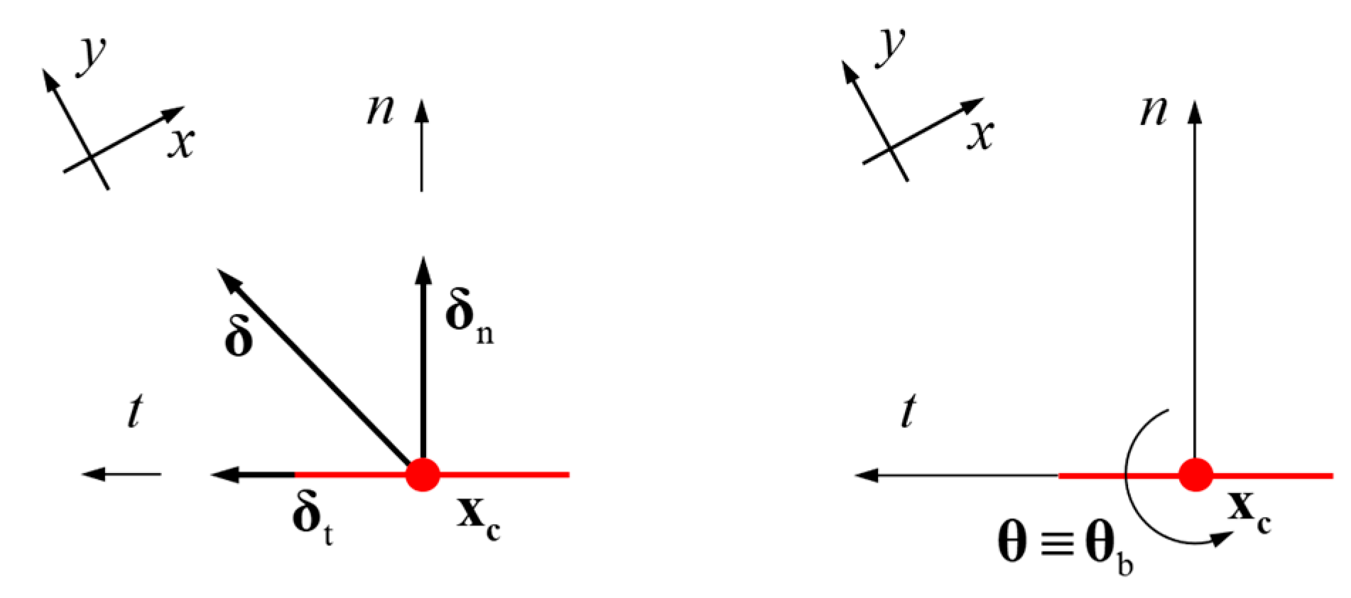
The normal unit vector of
n ×
t surface is defined as
for convenient calculation. Equations (5) and (6) can be obtained by decomposing the relative translational velocity
and the relative angular velocity
along
and
, respectively, as shown in
Figure 3.
where
is the relative translational velocity of the contact along
, with
;
is the relative translational velocity of the contact along
, with
; and
is the angular velocity around
at the contact.
Assuming that the time step is
, the relative displacement increment
and the relative rotation angle increment
of the contact can be expressed using Equations (7) and (8), respectively:
where
is the displacement increment along the coordinate axis
, with
, and
is the displacement increment along the coordinate axis
, with
.
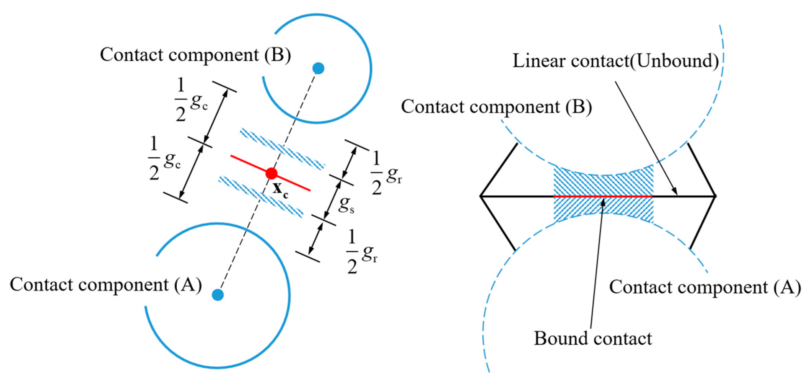
The contact kinematics law obtained from Equations (1)–(8) is the basis for judging the contact state and calculating the load transfer. It is assumed that the contact components contact each other and activate the contact model, when the traverse contact gap,
gs ≤ 0, is based on the reference contact distance of
gr, as shown in
Figure 4. The contact in the model can be regarded as a combination of linear contact (the contacts only transfer compression, but not tension and torque) and adhesive contact (the contacts are rigid connection) when the failure of cemented materials (such as rock) are calculated.
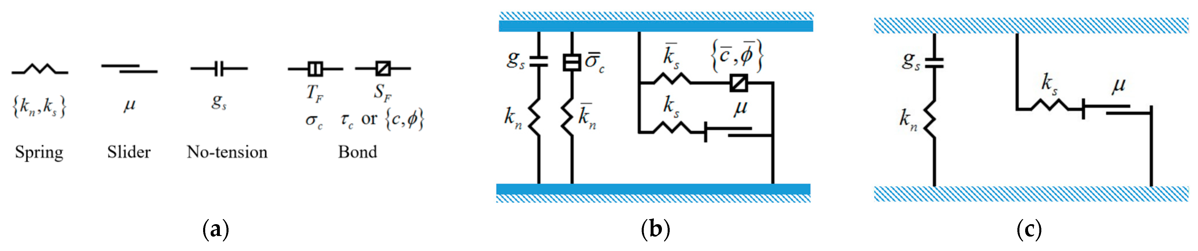
The linear contact model and the parallel-bond model are shown in
Figure 5 [
40]. The parallel-bond force and torque calculation formula is expressed in Equation (9):
where
and
are the contact force and contact torque, respectively;
is the linear contact force;
is the dashpot force;
is the parallel-bond force; and
is the parallel-bond moment.
According to the definition of the parallel-bond model, the parallel-bond stress
(tensile stress if
> 0) is calculated based on Equation (10). The bond will be broken when
, and
is defined as the bond strength. In this case,
,
, and the parallel-bond contact model changes to the linear contact model.
Here, is the normal parallel-bond force; is bonding cross-sectional area, with , , and in the 2D model; is the contribution coefficient of torque to contact stress, with ; is the parallel-bond moment; and is the moment of inertia, with .
6. Conclusions
This paper proposes a heterogeneous rock modeling method based on the discrete element theory and presents a rock-breaking model for a single PDC cutter. Using the proposed methods, the mechanisms and characteristics of cutting a heterogeneous gravel-bearing rock under a compound impact load are simulated and studied. Finally, field tests of the composite impactor in a gravel-bearing formation are carried out. The main conclusions for this paper are as follows:
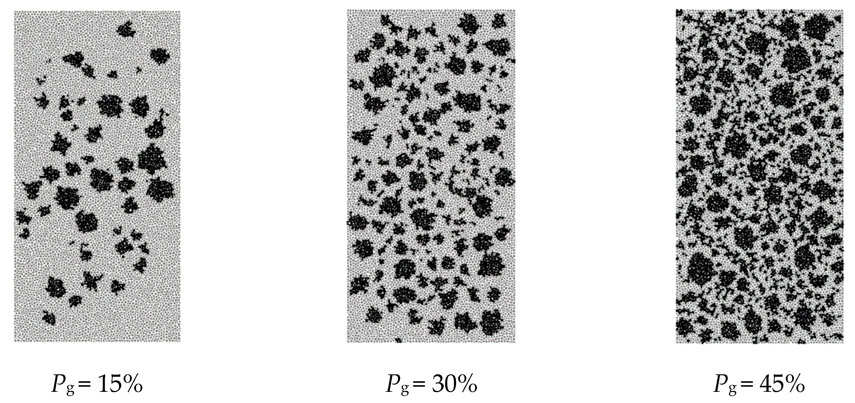
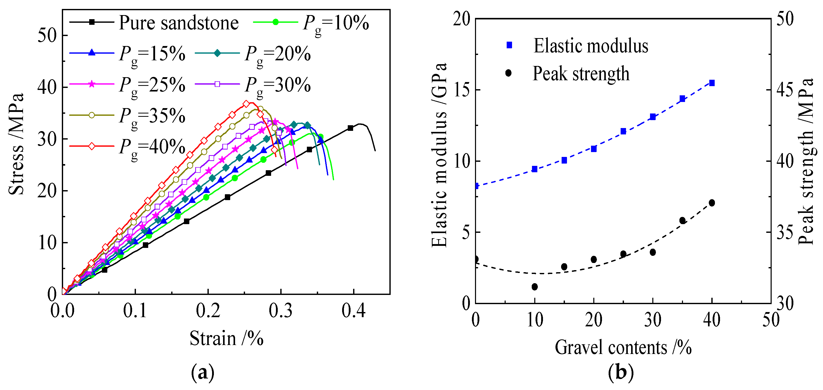
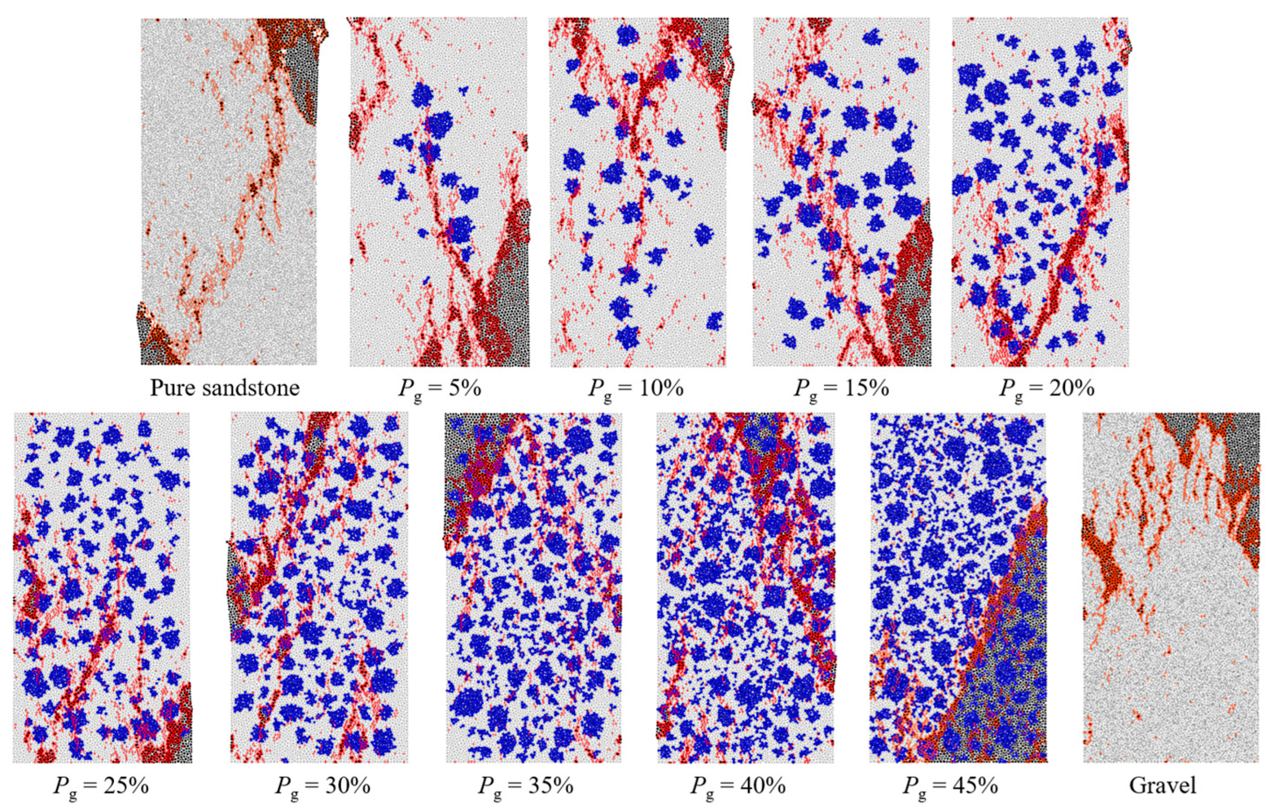
The random regular polygon filling method is a simple and feasible modeling method for heterogeneous rocks, which can simulate and analyze the crack growth, crushing state, and strength characteristics of heterogeneous rocks, such as gravel-bearing and hole-bearing rocks, by changing the distribution law of polygon, the geometric size, and the filling material parameters. The results show that the peak strength of the rock samples decreases slowly at first and then increases with an increase in the gravel content in the rock model. Compared to the peak strength, the increase in gravel content has a greater impact on the elastic modulus of the rock samples.
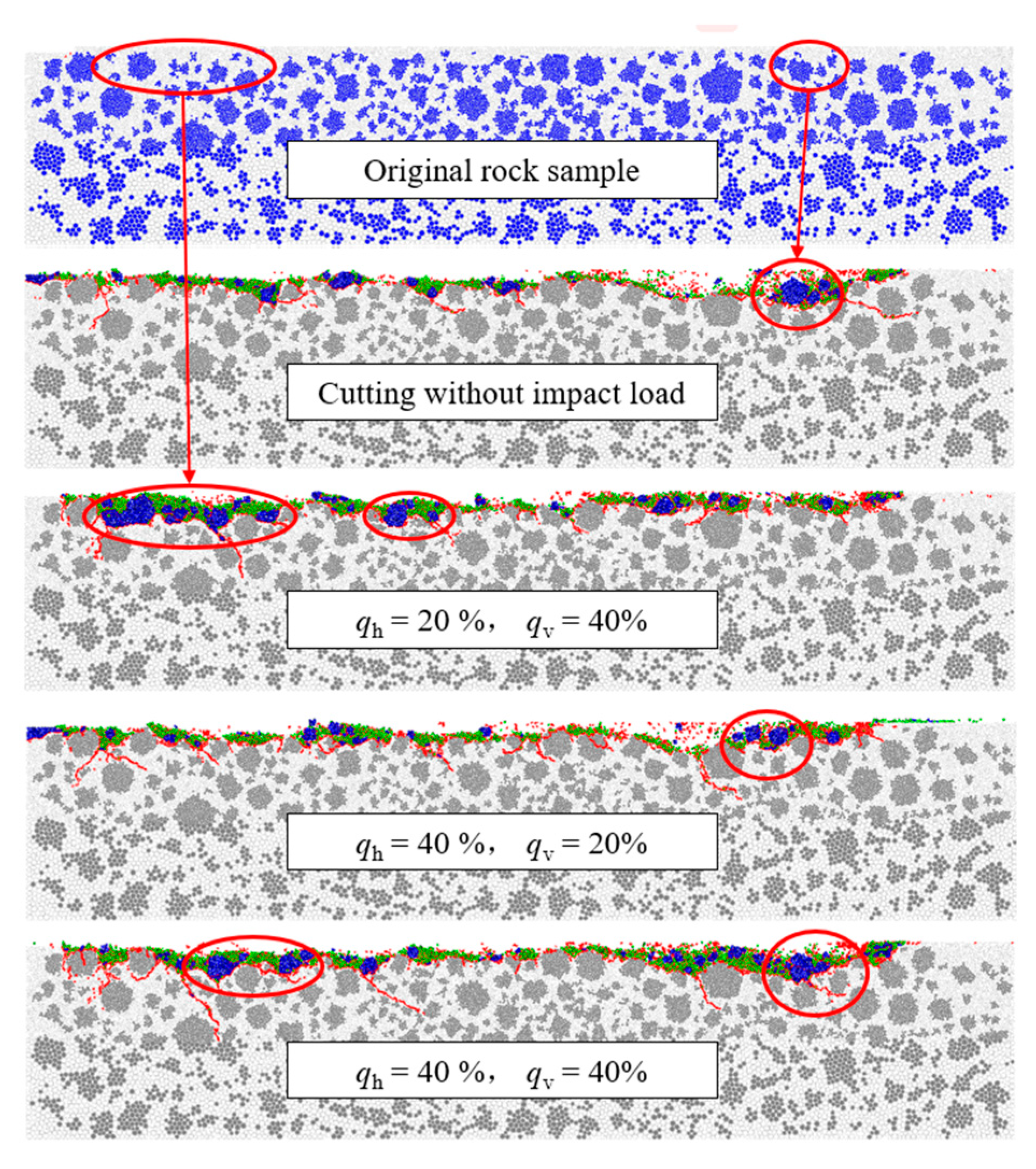
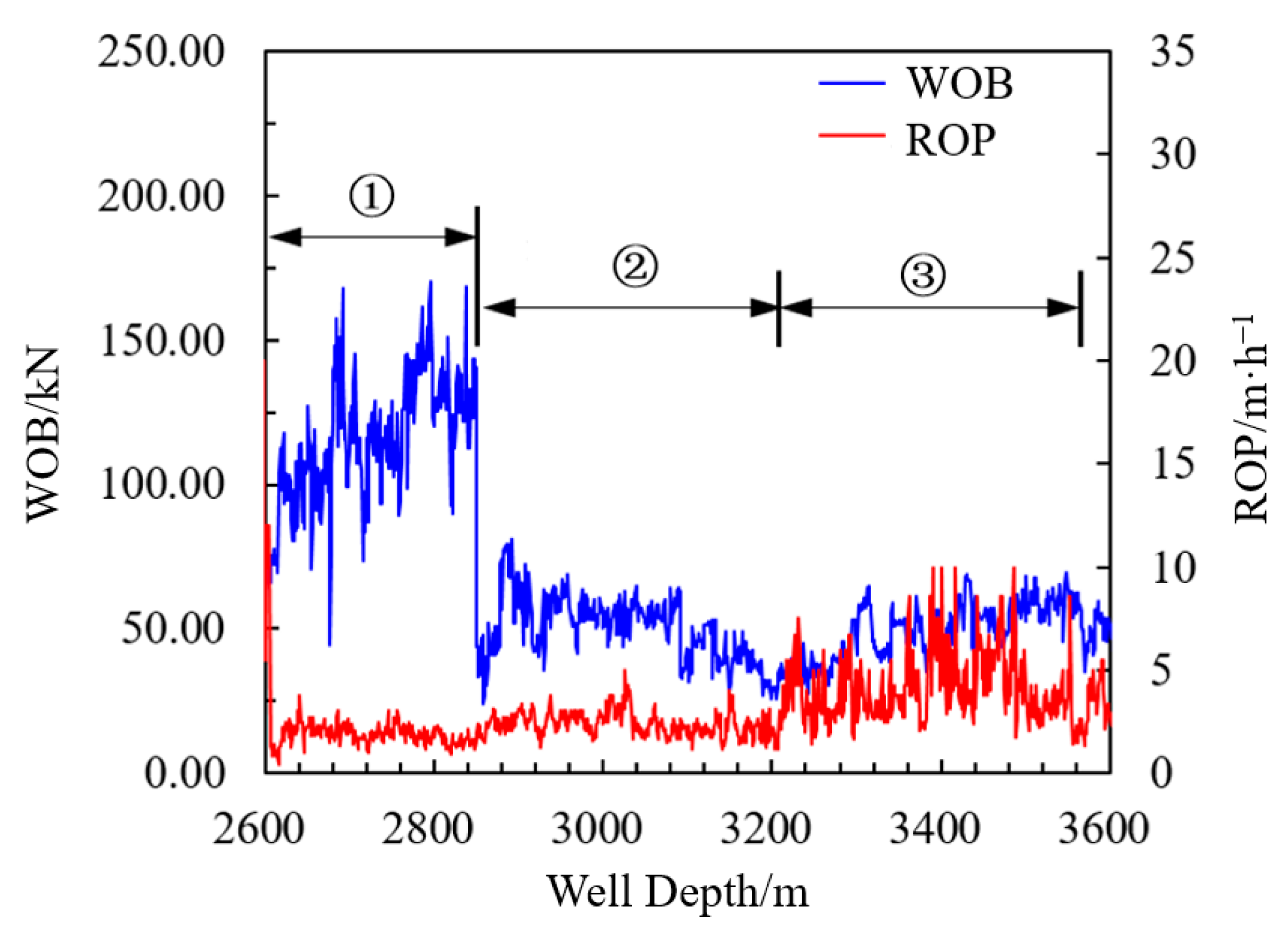
In the cutting process with a compound impact load, a higher horizontal impact amplitude coefficient (qh = 40%) has a more obvious effect on alleviating the vibration induced by the PDC cutting gravel-bearing rock. The field tests show that the composite impactor can remarkably reduce the vibration level in the gravel-bearing formation. The average WOB is reduced by 57.13%, the standard deviation of the WOB is reduced by 57.29%, and the average ROP is increased by 98.31%, compared to a conventional double-stabilizer BHA.
Improving the rock-breaking efficiency and the working life of PDC bits has always been the goal pursued by drilling engineering researchers. Optimizing the amplitude–frequency characteristics and the component ratio of the combined impact load plays a critical role in improving the ROP and suppressing bit vibration. In the future, the development of higher-performance composite impact tools and bits will be an important research direction to further improve drilling efficiency. For example, tools that automatically adjust the impact parameters will allow rapid adaptive drilling in different formations. Furthermore, with the mutual exchange and integration of multi-disciplines, it will become an important direction to carry out research on transformative rock-breaking methods when mechanical rock-breaking methods gradually reach their limit.


