Article

The Short-Circuit Fault Current Impact Mechanism and Adaptive Control Strategy of an MMC-HVDC

1
Research Institute, State Grid Sichuan Electric Power Co., Ltd., Chengdu 610041, China
2
Sichuan Provincial Key Laboratory of Power Internet of Things, Chengdu 610000, China
3
Electrical Engineering Department, Sichuan University, Chengdu 610065, China
*
Author to whom correspondence should be addressed.
Processes 2023, 11(3), 837; https://doi.org/10.3390/pr11030837
Submission received: 18 January 2023 / Revised: 14 February 2023 / Accepted: 20 February 2023 / Published: 10 March 2023
(This article belongs to the Special Issue 10th Anniversary of Processes: Women's Special Issue Series)

Abstract

:
A modular multilevel converter (MMC) is voltage-sourced and can supply fault currents to an AC system. To clarify the fault current impact mechanism of an MMC, this paper examines the control and capacitor discharge processes of an MMC when an AC system has a three-phase short grounding fault. The theoretical analysis shows that the outer loop control of the MMCs changes the fault injection. In different control modes, the nonzero reference value of the outer MMC loop forces the converter to inject and absorb the current into the AC system when a fault occurs. The limiter of the control determines the final injecting current value of the MMC. To help the MMC adjust the AC system’s fault current, adaptive strategies are also proposed, which include an adaptive reference control, an adaptive limiter control, and an adaptive capacitor control. On the basis of the proposed strategies, the fault currents could be increased or decreased within the MMC’s capacity. The simulations verify the theoretical analysis.

1. Introduction

Different kinds of power electronic equipment and renewable energy in power systems are continuously integrated into the traditional power grid [1,2,3,4,5,6], which has a significant impact on the short-circuit current of conventional AC systems from many aspects [4,5].
For example, to optimize China’s industrial structure and energy structure, the promotion of the carbon-neutrality strategy has allowed photovoltaic and wind power to develop rapidly. In some provinces, wind power has increased to several times its previous capacity. The impact of renewable energy on the energy structure and power source characteristics can no longer be ignored [6]. To find the specific impact, some scholars have carried out research on the impact of new energy grid connections on short-circuit current characteristics. The authors in [7,8] analyzed the short-circuit current characteristics of a doubly fed induction generator (DFIG) under crowbar protection. The control strategy and low inertia of the wind farm were the main reasons for the low short-circuit current. Specifically, because of the rotor speed variation of the DFIG, the frequency of the fault current was also different. For example, the frequency of the fault current was 40 Hz when the rotor speed decreased to 0.8 p.u. In [9,10], the authors studied the short-circuit current characteristics of a DFIG with different excitation control strategies, indicating that the control method was the key factor affecting the fault characteristics. The authors in [11] verified that when the control system had enough damping or the controller adopted effective anti-saturation measures, the fault current of the power grid containing the photovoltaic power supply did not have a peak, and the time to stabilization was very short. In addition, the smaller the output limit amplitude of the controller was, the longer it took for the three-phase fault current waveform of the photovoltaic power supply to stabilize. When the output limit of the d-axis controller was 0.2 p.u. and the output limit of the q-axis controller was 0.4 p.u., the duration of the transient fault current of the photovoltaic power supply reached nearly one frequency cycle. However, in the current short-circuit current calculation process, wind, photovoltaic, and other new energy sources are usually simplified rather than considering their different output characteristics and short-circuit current feeding mechanisms. The fault-current control strategy is also lacking. This is inconsistent with the actual operation, which seriously affects the accuracy of the fault current calculation and even endangers the safe operation of the power system.
On the other hand, the construction of electronic power equipment further leads to complex short-circuit current feeding mechanisms. Different types of high-voltage direct-current (HVDC) devices, a large number of flexible AC transmission systems (FACTS), and wind photovoltaic power electronic converters have made converters an important fault current injection source. HVDC technology comprises line-commutated-converter (LCC)-based HVDC and modular multilevel converter (MMC)-based HVDC devices. Research on the modeling, operation characteristics, and control strategies of the LCC-HVDC is relatively mature. In terms of the flexible DC transmission technology, the research has mainly focused on MMC modeling and control. Regarding the fault current, some researchers have clarified the DC side fault mechanism [12,13,14], such as the influence mechanism of the pole-to-ground fault currents in symmetrical monopole HVDC grids and the pole-to-pole fault currents in bipolar HVDC grids. A pole-to-pole fault current cannot be impacted by converters after the connection of two smoothing reactors, while a pole-to-ground fault current is influenced by all converters, where the DC side voltage is set to ±500 kV. The authors in [15] studied the transient process of an LCC-HVDC system with a three-phase fault on the AC side of the inverter and the mechanism of the short-circuit current fed by the LCC-HVDC system and proposed a practical calculation method for short-circuit currents. In [10], on the basis of the electric network theory, the authors derived a calculation method for the short-circuit currents of a unified power flow controller (UPFC) near buses and studied the fault control strategy. The influence of the operating conditions and the UPFC parameters on short-circuit currents was also investigated. Lastly, a simulation was carried out on the PSCAD simulation platform for verification. However, the above studies still did not clarify the fault current injection mechanism for HVDC systems, especially for MMC-HVDC systems. How to improve the fault current injection method of an MMC was also not studied.
The key point of the short-circuit current control is to increase the system-equivalent impedance at the fault point, that is, to increase the equivalent electrical distance [16]. Measures for limiting the short-circuit current can generally be divided into two types, traditional and new measures. On the one hand, traditional measures use high-impedance equipment, such as high-impedance generators and transformers, split-winding transformers and reactors, and current-limiting reactors. On the other hand, the power grid structure can also be changed, including the reasonable integration of the power source, hierarchical zoning, a bus splitting operation, line out of series, and disconnection [17,18]. New measures mainly adopt fault current limiters. All these fault current control methods do not take the MMC into consideration. Renewable power integration or the HVDC connection, namely, the MMC converter, plays an important role in a power grid. So, its impact on the fault current mechanism should be further clarified, and the fault current supplied by the MMC needs to be controlled. To solve this problem, this paper offers the following contributions.
  • The mechanism of the short circuit supplied by the MMC-HVDC system is clarified, and the main impact factors are analyzed.
  • To allow for the MMC to adjust its injected fault current, an adaptive reference control and an adaptive limiter control are proposed, which are easy to realize and effective in impacting the short circuits of AC systems.
  • To guarantee that the MMC can continuously impact an AC system’s fault current, an adaptive capacitor method is also proposed that can render the system more stable during the fault period.
The structure of the paper is as follows. Section 2 introduces the structure and control of an MMC-HVDC to clarify the basic theory of the paper. Section 3 then studies the fault current influence mechanism of the MMC and proposes different types of adaptive strategies to control the fault current of MMCs injected into an AC system. Section 4 describes the validation of the proposed strategy through simulations, and Section 5 presents the conclusions of the paper.

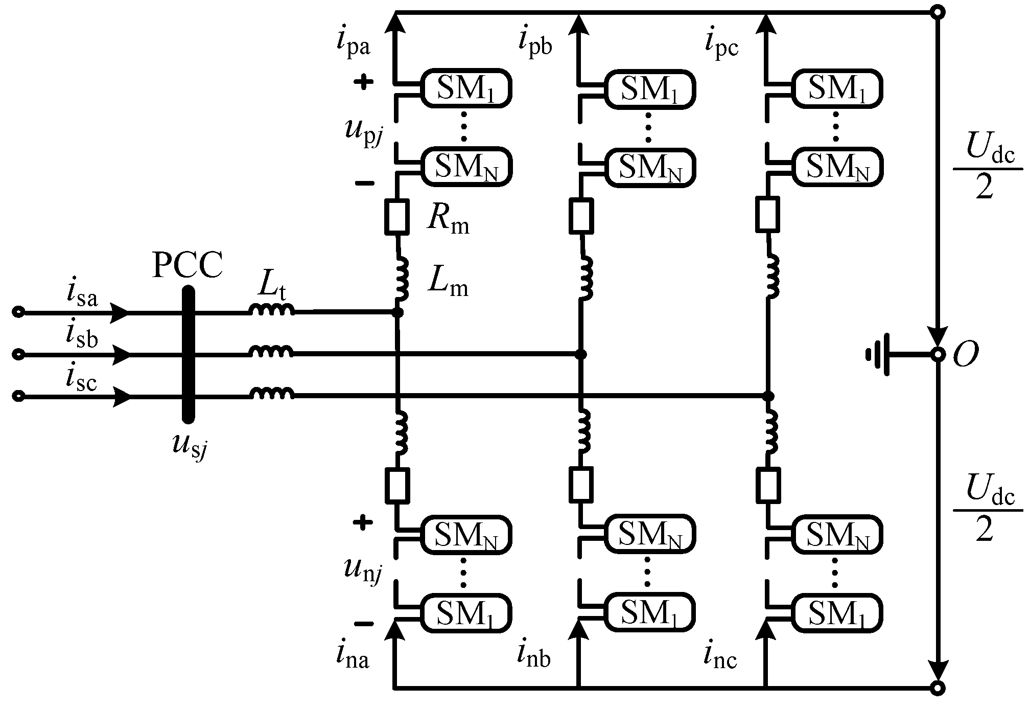
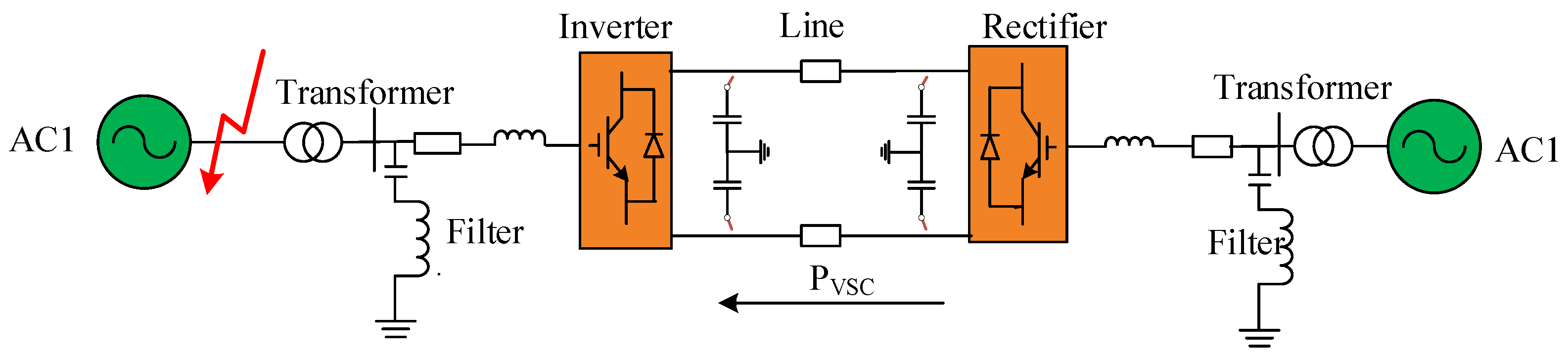
2. The Structure and Control of an MMC-HVDC

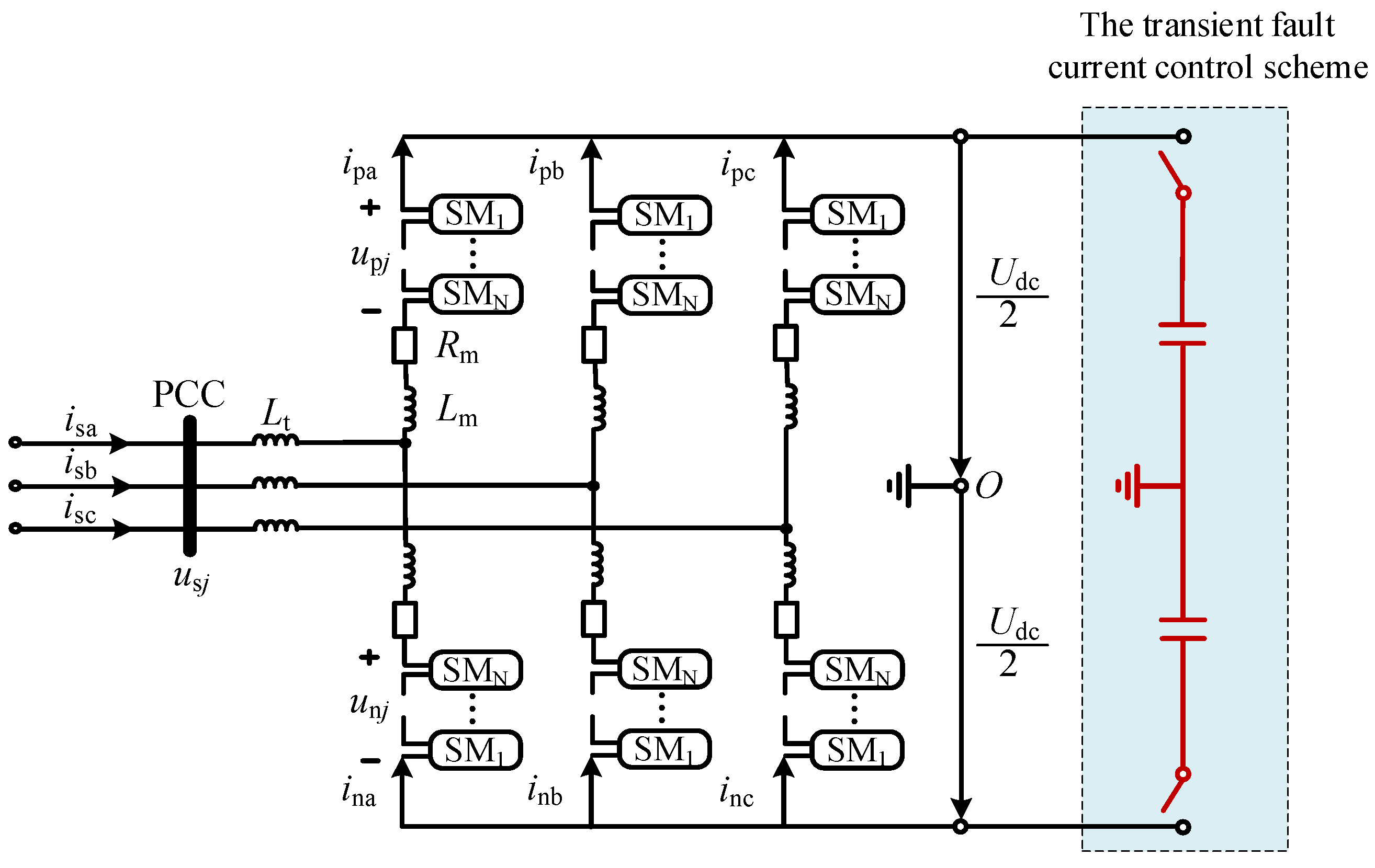
2.1. The Structure of an MMC-HVDC

The structure of an MMC-HVDC is shown in Figure 1. It contains six bridge arms, each of which has two N submodules (SM). Figure 1 presents the circuit structure of a half-bridge MMC 2. In the figure, isj and usj (j = a, b, c) are the three-phase current and voltage of the point of common coupling (PCC) on the AC side, respectively, ipj and inj are the currents of the upper and lower bridge arms of phase j, respectively, upj and unj are the voltages of the upper and lower bridge arms of phase j, respectively, Udc is the DC voltage, and Lt, Rm, and Lm are the leakage inductance, bridge arm resistance, and bridge arm inductance of the transformer connected to the valve, respectively.
In order to ensure the DC side voltage is constant, N submodules are deblocked in the same bridge arm at every moment. On the other side, in order to establish the three-phase voltage on the AC side, the MMC control system controls the opening and closing of the upper and lower bridge arm submodules at each time to generate corresponding AC waveforms. By writing the KVL equations of the MMC upper and lower bridge arms, we obtain the following relationships.
u s j + u p j R m i p j L m d i p j d t L t d i p j i n j d t = U dc 2
u s j u n j + R m i n j + L m d i n j d t L t d i p j i n j d t = U dc 2

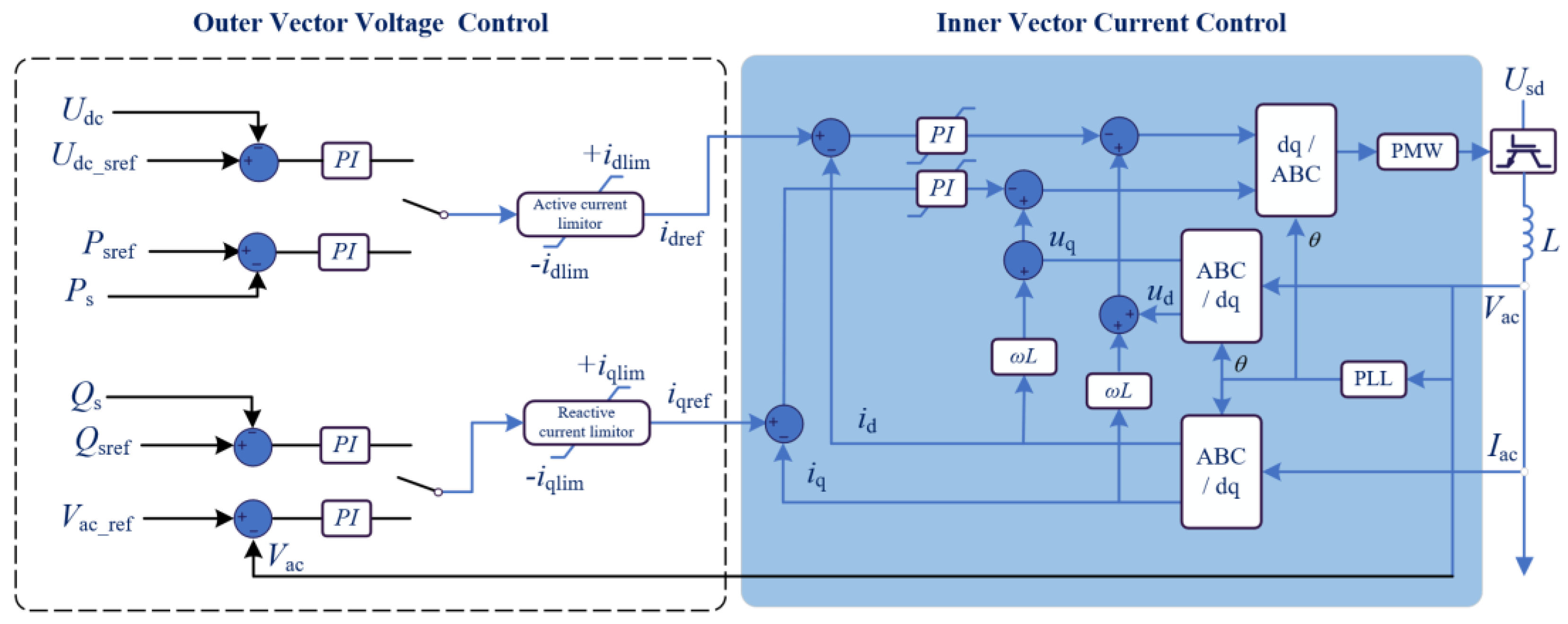
2.2. The Control of an MMC-HVDC

The control of an MMC is divided into indirect current control and direct current control. The indirect current control calculates the amplitude and phase of the inverter output AC voltage according to the control objectives and sends them to the valve level controller to generate a trigger pulse signal to control the switching of the submodule. The control structure of this control strategy is simple, but it is greatly affected by the strength of the AC system; the dynamic response of the AC current is slow, and the overcurrent of the converter valve cannot be limited. Thus, the MMC usually uses direct current control, which is composed of an outer loop voltage control and an inner loop current control. With fast current feedback control, the AC current can quickly track the change in the reference value and is widely used in high-voltage large-capacity transmission.
Figure 2 shows the direct current control of an MMC in detail. According to the control requirements, the inputs of the d-axis active power control include the active power and the DC voltage control, and the inputs of the q-axis reactive power control mainly include the reactive power and the AC voltage control. The deviation between the input value of the outer loop and the reference value is adjusted by the PI controller to obtain the input reference values idref and iqref of the inner loop current control. The inner loop current control adopts the current feedback and grid voltage feedforward control to generate the d and q-axis reference values, udref and uqref, of the virtual equal point fundamental wave voltage; then, the modulated wave is obtained through the Park inverse transformation.
Obviously, the P and Q can be independently controlled by adjusting the AC current components, idref and iqref, which realizes the decoupling control of the active power and the reactive power. The adjustment of the d-axis and q-axis components of the AC current is realized by the outer loop control, in which the Psref and the Ps denote the reference and the actual active power of the mainly controlled line, respectively, and Qsref and Qs denote the reference and the actual reactive power of the mainly controlled line, respectively. Vac_ref and Vac represent the AC voltage’s reference and actual value, respectively.

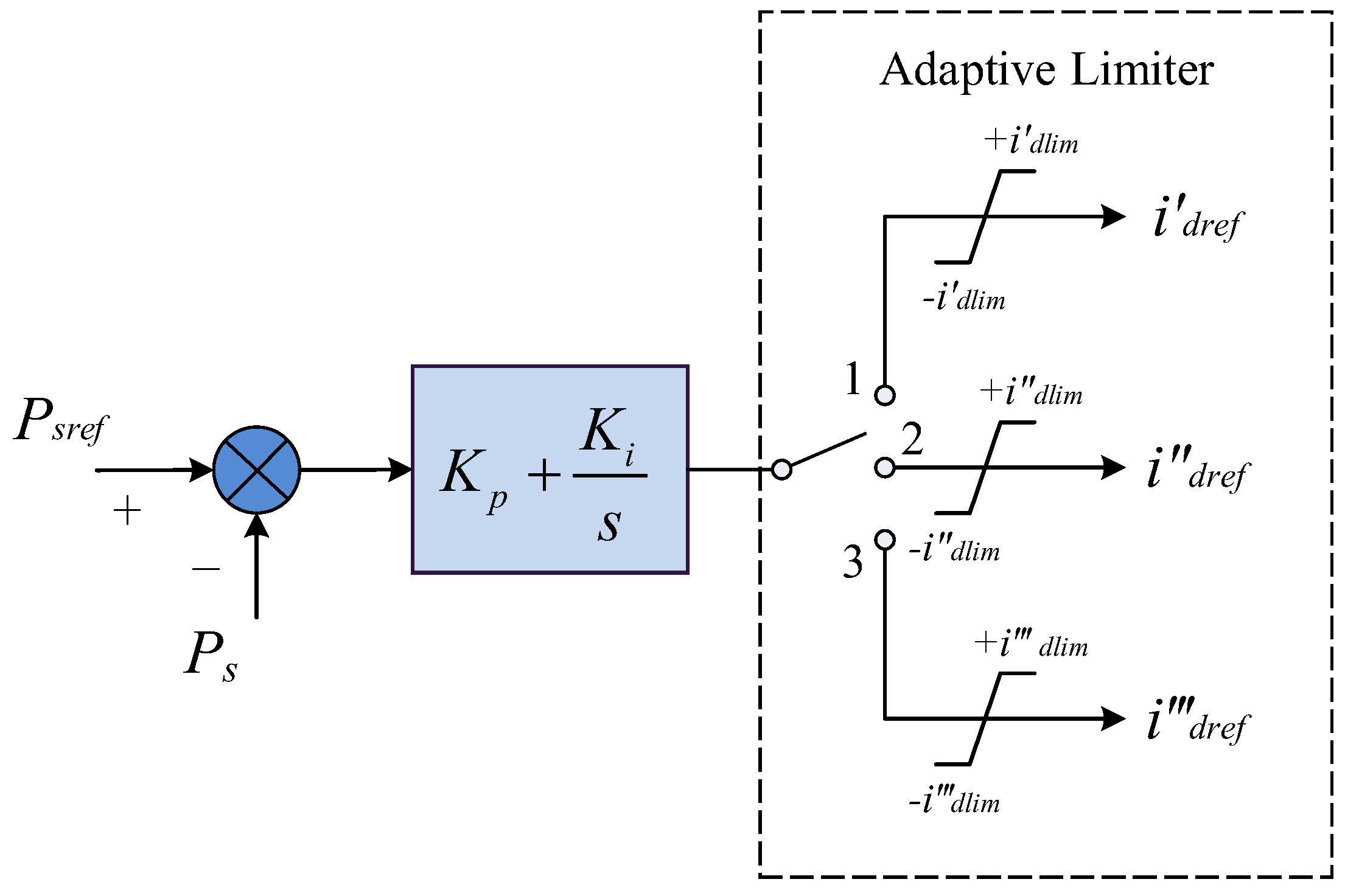
2.3. The Limiter of an MMC-HVDC

The detailed outer controls of the active power and reactive power control described above are shown in Figure 3 and Figure 4, respectively, where Kp is the proportional coefficient of the constant active power controller, and Ki is the integration coefficient; idlim and iqlim are the limiting amplitudes of the d-axis and q-axis currents (active and reactive currents), respectively.
The outer current control loops of the active and reactive control are both limited. Usually, the MMC-HVDC limits the outer current ilim to 1.1 times its rated current irated, which is shown in (3):
i lim = 1.1 i r a t e d
In (3), the ilim is the total current composed of the active current idlim and the reactive current iqlim. They have the relationship expressed by Equation (4):
i lim = i d lim 2 + i q lim 2
The limiter of the MMC-HVDC has three types, as shown in Figure 5. In the first type of limiter, namely type I, the active current limiter has the same priority as the reactive current limiter. In the second type of limiter, namely type II, the reactive current limiter has priority, while the active current limiter does not. In the third type of limiter, namely type III, the active current limiter has priority, while the reactive current limiter does not. Usually, to guarantee active power transmission, the practical project always adopts the third type of limiter.

3. The Fault Current Influence Mechanism of the VSC and the Control Strategy

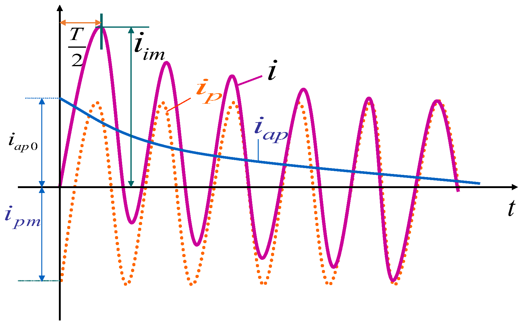
3.1. The Fault Current Influence Mechanism

An important criterion for the safe operation of flexible DC transmission systems is the balance of the input and output power. If the input power is greater than the output power, the DC voltage rises; otherwise, the DC voltage drops, and the system is unstable.
The nearby three-phase short-circuit fault has the greatest impact on the converter station, namely the short-circuit fault at the point of common coupling (PCC). When a three-phase short-circuit fault occurs in the near-area AC system of the converter station, the transmission power of the converter station drops sharply in an instant. At this time, the transmission power of the converter station is close to 0.
According to the basic three-phase short-circuit fault mechanism, the fault current i can be divided into a periodic component and a non-periodic component, which are ip and iap, respectively, shown in Figure 6. The maximum possible instantaneous value of the short-circuit current, namely the short-circuit impulse current iim, is mainly used to verify the electrodynamic stability of the electrical equipment. It is determined by the non-periodic component and impacts the transient-state fault currents. The periodic component of the fault current is usually used for system strength analysis and impacts the steady-state fault currents.
Thus, this section takes the three-phase short-circuit fault at the PCC as the research object and studies the response process of the converter station after the fault. Based on the operation principle of the converter station, the influence of the converter station on the short-circuit current of the AC system, the characteristics of the short-circuit current, and the influencing factors are analyzed.
After a three-phase short-circuit fault occurs at the PCC, the AC voltage, the active power, and the reactive power at the PCC point become 0. For a constant active power control mode, the control relationship can be obtained as
i dref = K p ( P sref P s ) + K i ( P sref P s )
where Kp is the proportional coefficient of the constant active power controller, Ki is the integration coefficient, Psref is the active power setting value, which is not 0, and Ps is the actual value of the active power.
After the fault, the actual active power Ps output by the converter station decreases instantaneously, while the Psref remains unchanged. It can be seen from Formula (5) that the absolute value of idref is always increasing. However, due to the existence of the limiter, idref reaches its maximum value, namely idref_max, especially, if Psref = 0, and Ps = 0, idref = 0 during normal operation. The d-axis reference current output by the outer loop controller remains unchanged after the fault and does not reach the maximum value, namely idref = 0.
i dref = K p ( U sref U s ) + K i ( U sref U s )
For the constant DC voltage control mode, the situation is similar to the constant active power control according to (6), where Usref is the DC voltage setting value, which is not 0, Us is the actual value of DC voltage, Kp is the proportional coefficient of the constant active power controller, and Ki is the integration coefficient. As the reactive power control usually has a smaller limit value compared with the active power control loop, its impact on the three-phase fault is not discussed in this paper.

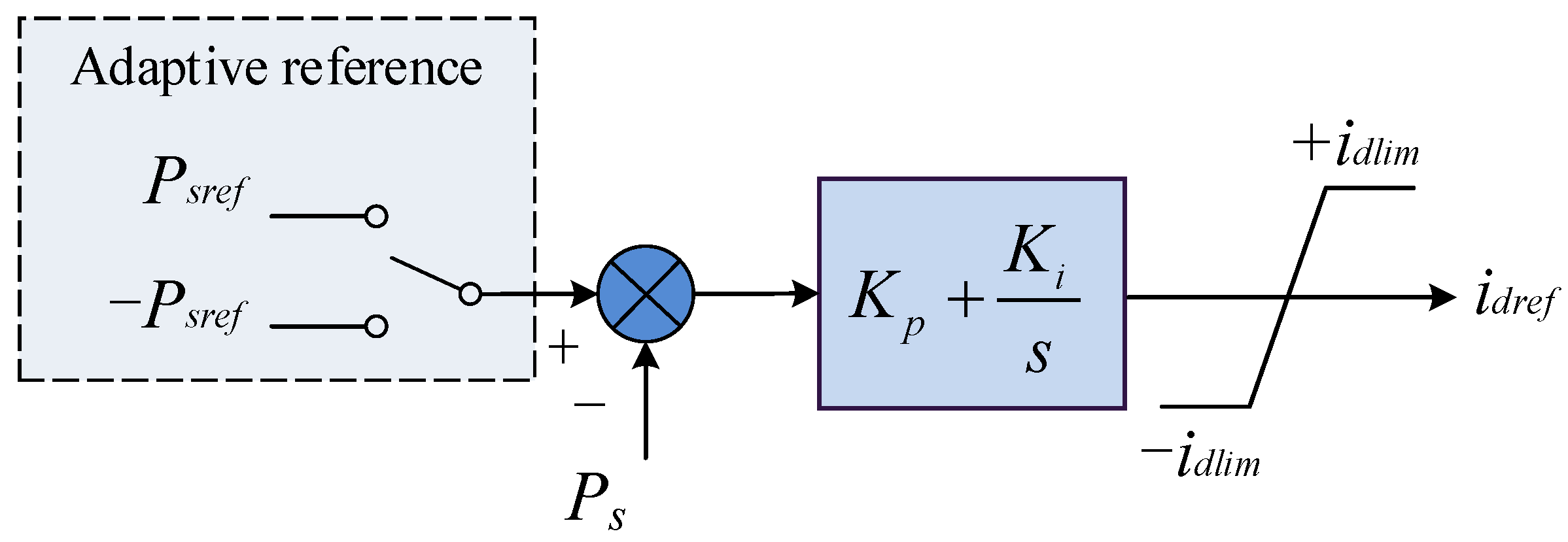
3.2. The Adapative Control Strategy

According to the analysis above, it can be concluded that the steady-state short-circuit fault current, namely the periodic component, supplied by the MMC is mainly decided by two parts. The first part, which is the most important part, is decided by the limiter of the outer current control. Thus, if the limiter can be controlled during the fault period, the fault current supplied by the MMC can be impacted. In some conditions, the fault current level of the AC system is too high, and it is beneficial to decrease the fault current of the MMC, while in some other situations, the MMC is supposed to support the AC system, and so a larger fault current of the MMC is preferred.
Based on such demand, an adaptive limiter can be designed to control the steady-state fault current supplied by the MMC. The adaptive limiter was designed as Figure 7 shows. The limiter has three limitation loops. In normal operation, the system selects channel 2 as the limiter with normal settings, in which the i″dlim equals 1.1 p.u., and the i″dref is the output of the normal active current. The outputs of channel 2 can be described by Equation (7). The i″dref always equals its positive limitation i″dlim when the active power reference Psref is not zero. Once the active power reference Psref is zero, the output becomes zero too.
i dref = + i dlim , P sref 0 0 , P sref = 0
When it is in the fault current limitation situation, the adaptive limiter can choose channel 3, in which the i‴dlim is less than 1.1 p.u., and the output active current i‴dref can be decreased to limit the injected fault current from the MMC. However, if the active power reference Psref is set to zero, the injected fault current will also be zero, as Equation (8) shows.
i dref = + i dlim , P sref 0 & i dlim < 1.1 0 , P sref = 0 & i dlim < 1.1
On the other side, if the fault current supplied by the MMC is supposed to increase, the limiter can select channel 1, where the i′dlim is larger than 1.1 p.u., and the output active current i′dref can be enlarged to make the MMC supply more fault current and improve the AC system’s stability. Similarly, the injected fault current is zero when the active power reference Psref is set to zero, as Equation (9) shows.
i dref = + i dlim , P sref 0 & i dlim > 1.1 0 , P sref = 0 & i dlim > 1.1
As mentioned above, another important fault current impact factor of an MMC is the active power reference. Usually, for an MMC inverter, the power reference is set to a positive value for the output active power. In such a situation, the MMC injects a fault current into the AC system. On the other side, if the power reference is negative, the MMC absorbs the fault current to decrease the fault current. Based on this phenomenon, an adaptive reference was designed, as Figure 8 shows. In Figure 8, the power reference channel also has two selections, namely the positive channel and the negative channel. If the fault current needs to be increased, the positive reference channel Psref can be selected to cause the MMC to supply the fault current. Similarly, if the fault current needs to be decreased, the negative reference channel −Psref can be selected to cause the MMC to absorb the fault current.
The mathematical description of the adaptive reference control is shown in (10). The output of idref equals +idlim when the positive reference channel is selected, while the output of idref equals −idlim when the negative reference channel is selected. Similarly, the output becomes zero, if the reference is zero.
i dref = + i dlim , P sref 0 0 , P sref = 0 i dlim , P sref 0

3.3. The Adapative Capacitor Strategy

It is obvious that the fault current also has a transient part, namely the non-periodic component. In the increased fault current situation, the system not only needs to enlarge the steady-state fault current but the transient fault current should also be improved, as some electronic power devices respond very quickly. For a voltage-sourced converter, the DC side usually has capacitors to store the energy. The MMC usually stores the energy in the submodule, so a lumped capacitor is not necessary. However, to ensure the transient fault current can be adjusted, the lumped capacitor was also equipped, as Figure 9 shows. To increase the fault current, the capacitor can be switched on in normal operation and then release the storage energy when a fault occurs. To decrease the fault current, the capacitor can be switched off during normal operation and switched on during the fault period.
It should be mentioned that if the renewable power of an off-shore wind farm is output by an MMC-HVDC, the wind farm side of the MMC is usually in island control, namely a constant AC frequency and a constant AC voltage control. In addition, the grid-side MMC is usually in a constant DC voltage control and a constant reactive power control. It can be seen that each side of the MMC is not in a constant active power control. Hence, the proposed strategy could not be applied in this situation.

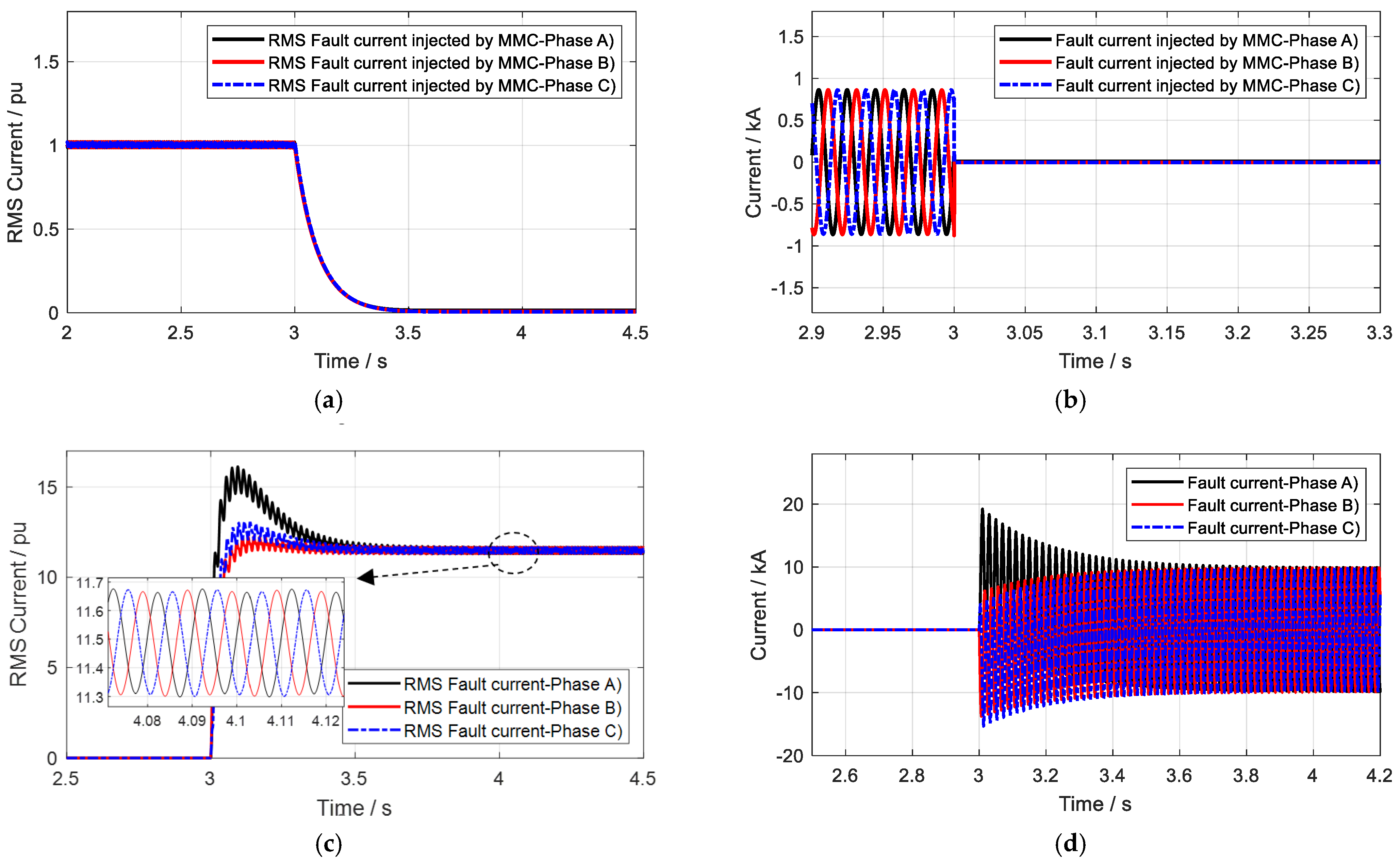
4. Simulation Verifications

The topology of the test system is presented in Figure 10. The system was a two-terminal MMC-HVDC, and the system parameters can be found in Table 1 and Table 2.

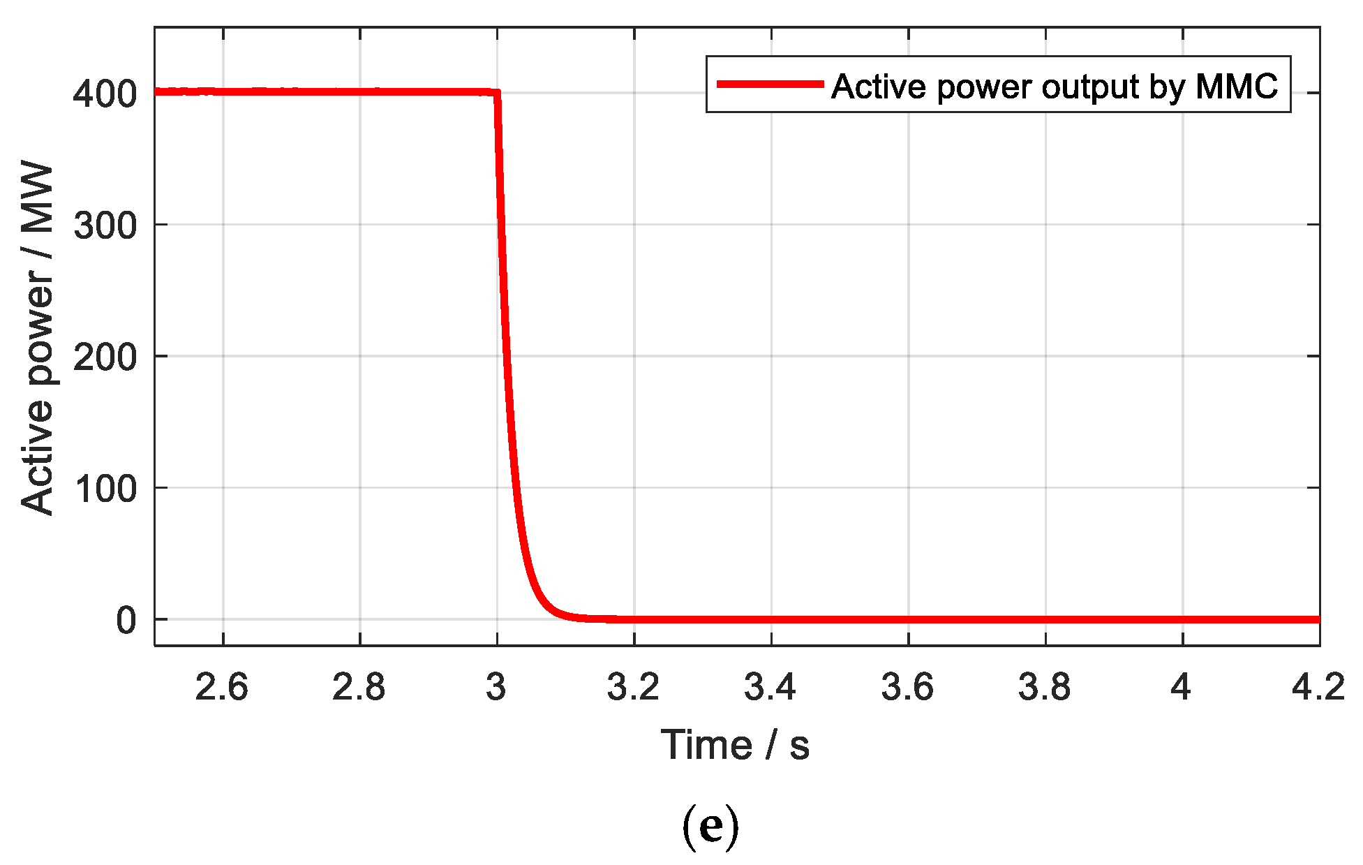
4.1. Case 1 Study: An MMC without Adaptive Control

In this case, the MMC-HVDC operated in the normal condition. The HVDC system was blocked after the fault occurred. To verify that no short circuit was supplied without additional adaptive control, the system shown in Figure 10 was set to provide a three-phase short-circuit fault at 3 s. The DC system transmitted 400 MW of active power. The results of the RMS short-circuit current injected by the MMC after the fault, the instantaneous short-circuit current injected by the MMC after the fault, the RMS short-circuit current of the whole system, the instantaneous short-circuit current of the whole system, and the active power transmitted by the MMC are presented in Figure 11, respectively.
It can be seen from Figure 11a,b that the fault current injected by the MMC was zero when no adaptive strategies were added. This was because the HVDC system was suddenly blocked, and no current could be supplied by the MMC after the fault. Figure 11e shows that the active power became zero, which was consistent with figures (a) and (b). The fault current became stable after about 0.5 s, while the active power of the MMC decreased to 0 after about 0.1 s. Figure 11c,d denotes that the system fault current at a steady state maintained a value of 11.5 p.u., which was the total fault current that the AC system could supply, and the base voltage of this value was 400 kV and 400 MV.

4.2. Case 2 Study: MMC with a Positive Adaptive Reference Control

In this case, the adaptive control was added to the MMC to impact the AC fault current. Specifically, the adaptive reference was set to positive to strengthen the AC fault current. The three-phase short-circuit fault was also set at 3 s. The results of the RMS short-circuit current injected by the MMC after the fault, the instantaneous short-circuit current injected by the MMC after the fault, the RMS short-circuit current of the whole system, the instantaneous short-circuit current of the whole system, and the active power transmitted by the MMC are presented in Figure 12, respectively.
It can be seen from Figure 12a,b that the fault current injected by the MMC was 1.1 p.u. when the positive adaptive reference strategy was added. This was because the value of the limiter in the MMC was 1.1 p.u., according to Table 2. Figure 11c,d denotes that the system fault current at a steady state maintained a value of 12.6 p.u., which was the sum of 11.5 and 1.1. This proves that the positive adaptive reference strategy increased the AC fault current by 1.1 p.u, which was the maximum current the MMC could supply if no other methods were used. Similarly, the AC system’s fault current became stable after about 0.5 s, and the fault current supplied by the MMC was also stable after 0.5 s, where the active power of the MMC decreased to 0 after about 0.1 s. The overshoot of the fault current supplied by the MMC reached 2 p.u., and the base voltage of this value was 400 kV and 400 MV.

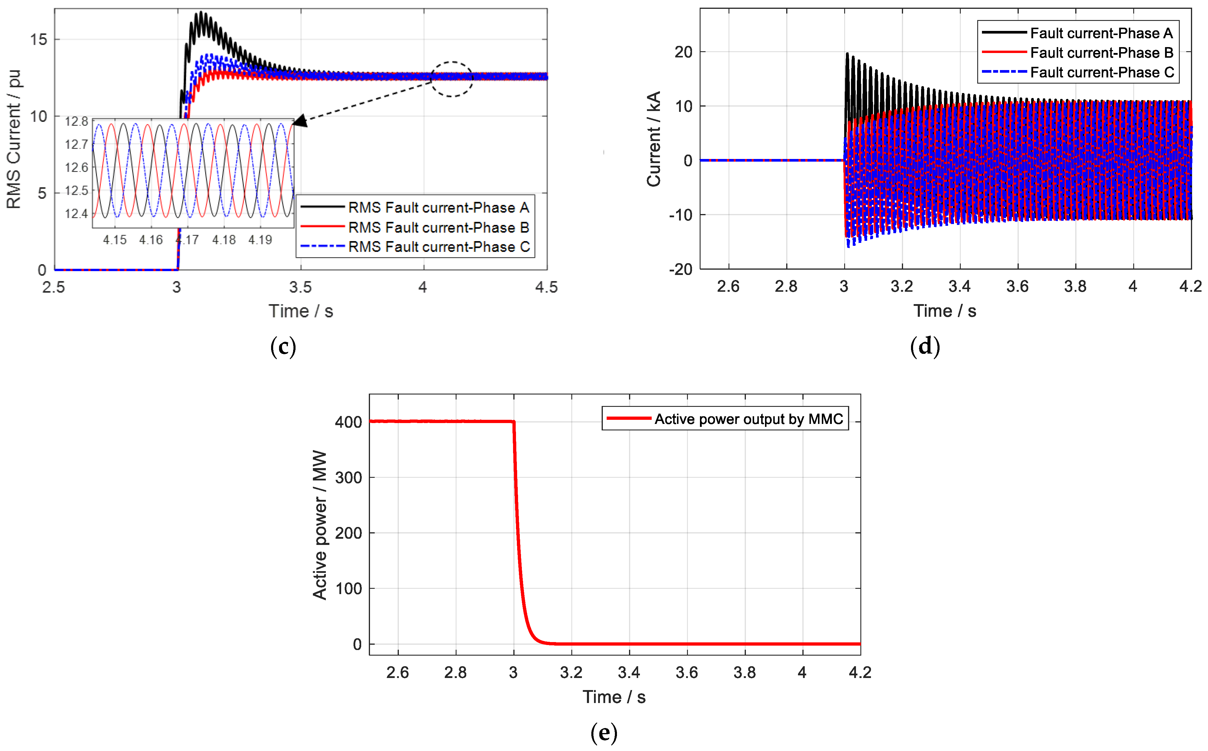
4.3. Case 3 Study: The MMC with a Negative Adaptive Reference Control

In this case, the adaptive control was added to the MMC to impact the AC fault current. Specifically, the adaptive reference was set to negative to decrease the AC fault current. The three-phase short-circuit fault was also set at 3 s. The results of the RMS short-circuit current injected by the MMC after the fault, the instantaneous short-circuit current injected by the MMC after the fault, the RMS short-circuit current of the whole system, the instantaneous short-circuit current of the whole system, and the active power transmitted by the MMC are presented in Figure 13, respectively.
Figure 13a,b shows that the fault current transmitted by the MMC was 1.1 p.u., but it was actually negative; as the RMS value cannot be negative, the figure only presents the positive values. Figure 13c,d denotes that the system fault current at a steady state maintained the value of 10.4 p.u., which also proves that the negative adaptive reference strategy decreased the AC fault current by 1.1 p.u. Similarly, the AC system’s fault current became stable after about 0.5 s, and the fault current supplied by the MMC was also stable after 0.5 s, where the active power of the MMC decreased to 0 after about 0.1 s. The overshoot of the fault current supplied by the MMC reached less than 2 p.u. because the reference was negative, and the base voltage of this value was 400 kV and 400 MV.

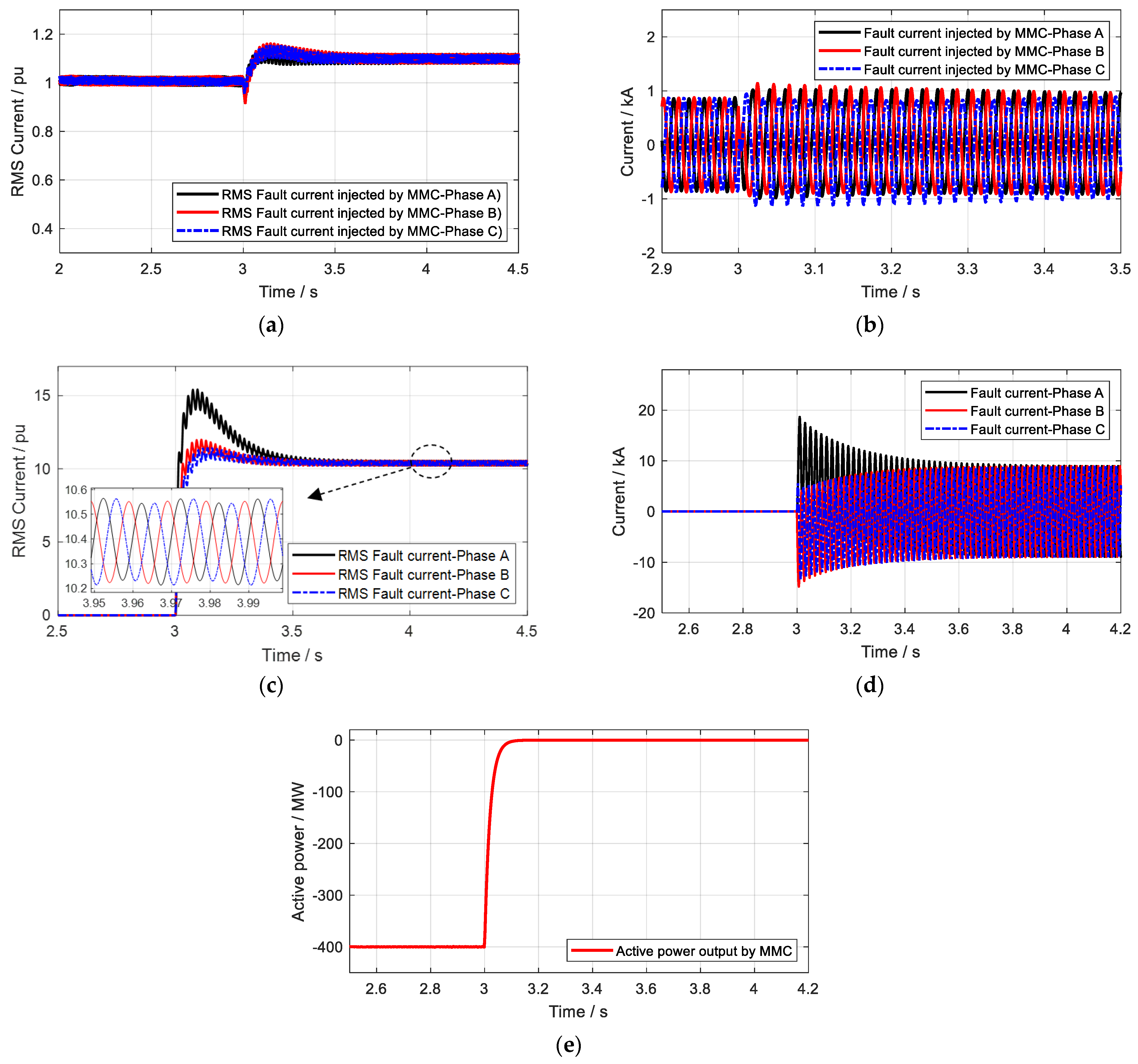
4.4. Case 4 Study: The MMC with an Adaptive Limiter Control

In this case, the adaptive limiter control was added to the MMC to impact the AC fault current. The limiter was set at 1.5 p.u. when a fault occurred, while it was 1.1 p.u. in normal operation. The DC system transmitted 20 MW in this case, and the three-phase short-circuit fault was also set at 3 s. The results of the RMS short-circuit current injected by the MMC after the fault, the instantaneous short-circuit current injected by the MMC after the fault, the RMS short-circuit current of the whole system, the instantaneous short-circuit current of the whole system, and the active power transmitted by the MMC are presented in Figure 14, respectively.
It can be seen from Figure 14a,b that the fault current transmitted by the MMC became 1.5 p.u., and Figure 13c shows that the system fault current at a steady state increased to the value of 13 p.u., which further proves that the adaptive limiter strategy strengthened the AC fault current. The AC system’s fault current became stable after about 0.5 s, and the fault current supplied by the MMC was also stable after 0.5 s, where the active power of the MMC decreased to 0 after about 0.1 s. The overshoot of the fault current supplied by the MMC disappeared this time because the limiter was greatly enlarged. For a better understanding, Table 3 presents the different results with the different control strategies.

4.5. Case 5 Study: The MMC with an Adaptive Capacitor

In this case, the adaptive capacitor was added to the MMC to impact the AC fault current. The three-phase short-circuit fault was also set at 3 s. The results of the RMS short-circuit current injected by the MMC after the fault, with and without the adaptive capacitor, are shown in Figure 15a,b. The RMS short-circuit current of the whole system after the fault, with and without the adaptive capacitor, is shown in Figure 15c,d.
It can be seen clearly that the system with the adaptive capacitor continuously injected the fault current to the AC system such that the AC system’s fault current was adjusted. The system without the adaptive capacitor was unstable and could not be used to impact the AC system’s fault current.

5. Conclusions

According to the study, it can be concluded that the MMC-HVDC impacts the AC system’s short-circuit fault current in two respects. The first aspect refers to its outer-loop control. In terms of the power reference, the limiter value of the outer-loop control decides the fault current injected values. The second aspect refers to the capacitor components, which decide the time of stability of the fault current injection. To increase the fault current supplied by the MMC, the positive adaptive reference control can be applied, while the negative adaptive reference can decrease the MMC-injected fault current. The adaptive limiter can influence how much fault current the MMC can inject into and absorb from the AC system. The larger the limiter value, the greater the impact of the MMC. The adaptive capacitor can guarantee the stability of the MMC when it injects the fault current into the AC system, as more energy can be released when a fault occurs.

Author Contributions

X.W. conceptualization, writing—original draft; Z.C. writing—review and editing; Q.J. software, data curation; Y.Z. software, data curation, writing—review and editing; B.L. writing—review and editing; Y.H., Q.L. and B.L. software, writing—review and editing. All authors have read and agreed to the published version of the manuscript.

Funding

This work was supported by the Science and Technology Project of the State Grid Sichuan Electric Power Company (The short-circuit current practical calculation method research in the multi-power-source background, 521997220013) and by the Sichuan Science and Technology Plan Project (2021JDTD0016).

Institutional Review Board Statement

Not applicable.

Informed Consent Statement

Not applicable.

Data Availability Statement

Not applicable.

Conflicts of Interest

The authors declare no conflict of interest.

Abbreviations

MMCModular multilevel converter
ACAlternate current
HVDCHigh-voltage direct current
DFIGDoubly fed induction generator
FACTSFlexible AC transmission systems
LCCLine-commutated converter
UPFCUnified power flow controller
PCCPoint of common coupling
SMSubmodules
RMSRoot mean square

References

  1. Jiang, Q.; Zeng, X.; Li, B.; Wang, S.; Liu, T.; Chen, Z.; Wang, T.; Zhang, M. Time-Sharing Frequency Coordinated Control Strategy for PMSG-Based Wind Turbine. IEEE J. Emerg. Sel. Top. Circuits Syst. 2022, 12, 268–278. [Google Scholar] [CrossRef]
  2. Li, B.; Chen, S.; Liu, T. Theoretical analysis on the VSC instability caused by PLL in weak system. IET Renew. Power Gener. 2020, 14, 1782–1788. [Google Scholar] [CrossRef]
  3. Ding, Z.; Yuan, K.; Qi, J.; Wang, Y.; Hu, J.; Zhang, K. Robust and Cost-Efficient Coordinated Primary Frequency Control of Wind Power and Demand Response Based on Their Complementary Regulation Characteristics. IEEE Trans. Smart Grid 2022, 13, 4436–4448. [Google Scholar] [CrossRef]
  4. Chen, C.; Zhang, X.; Cui, M.; Zhang, K.; Zhao, J.; Li, F. Stability assessment of secondary frequency control system with dynamic false data injection attacks. IEEE Trans. Ind. Inf. 2022, 18, 3224–3234. [Google Scholar] [CrossRef]
  5. Wang, Y.; Gao, J.; Zuo, Z.; Han, Q.; Zhang, W. Periodic zero-dynamics attacks for discrete-time second-order multi-agent systems. Int. J. Robust Nonlinear Control 2022, 32, 5619. [Google Scholar] [CrossRef]
  6. Li, B.; Chen, S.; Liu, T. Improved practical method for Low-inertia VSC-HVDC stability analysis in weak system. IET Gener. Transm. Distrib. 2020, 14, 5072–5079. [Google Scholar] [CrossRef]
  7. Zhang, B.; Li, G.; Wang, J.; Hao, Z.; Liu, Z.; Bo, Z. Affecting factors of grid-connected wind power on fault current and impact on protection relay. Electr. Power Autom. Equip. 2012, 32, 1–8. [Google Scholar]
  8. Samaan, N.; Zavadil, R.; Smith, J.C.; Conto, J. Modeling of wind power plants short circuit analysis in the transmission network. In Proceedings of the IEEE PES 2008 Transmission and Distribution Conference and Exposition, Chicago, IL, USA, 21–24 April 2008; pp. 1–7. [Google Scholar]
  9. Zhao, C.; Qi, L.; Chen, N.; Cui, X.; Ma, J. Research on Producing Mechanism of Healthy Pole Bus Overvoltage for Monopolar Grounding Fault in ±500kV Zhangbei Flexible DC Power Grid. Power Syst. Technol. 2019, 43, 530–536. [Google Scholar]
  10. Zhou, N.; Zhang, Z.; Liang, T.; Ying, W.; Bo, Y. Short-circuit Current Calculation Method for Near-end Bus of Unified Power Flow Controller. Autom. Electr. Power Syst. 2020, 44, 95–102. [Google Scholar]
  11. Kong, X.; Yuan, Y.; Huang, H.; Zhu, W.; Li, P.; Wang, Y. Fault Current Transient Features and Its Related Impact Factors of PV Generator. Power Syst. Technol. 2015, 39, 2444–2449. [Google Scholar]
  12. Tao, Y.; Li, B.; Dragičević, T.; Liu, T.; Blaabjerg, F. HVDC grid fault current limiting method through topology optimization based on genetic algorithm. IEEE J. Emerg. Sel. Top. Power Electron. 2020, 9, 7045–7055. [Google Scholar] [CrossRef]
  13. Tao, Y.; Li, B.; Liu, T. Pole-to-ground fault current estimation in symmetrical monopole high-voltage direct current grid considering modular multilevel converter control. Electron. Lett. 2020, 56, 392–395. [Google Scholar] [CrossRef]
  14. Jiang, Q.; Li, B.; Liu, T.; Wang, P. Fault current limiting method based on virtual impedance for hybrid high-voltage direct current with cascaded MMC inverters. Electron. Lett. 2021, 57, 229–231. [Google Scholar] [CrossRef]
  15. Wang, T.; Wan, L.; Zhang, Y.; Bu, G. Study of the short circuit current contributed by a DC system with a three-phase fault on the AC side of an inverter. In Proceedings of the 2015 IEEE Power & Energy Society General Meeting, Denver, CO, USA, 26–30 July 2015; pp. 1–5. [Google Scholar] [CrossRef]
  16. Sadeghi, A.; Seyyedbarzegar, S.; Yazdani-Asrami, M. Investigation on the Electrothermal Performance of a High-Temperature Superconducting Cable in an Offshore Wind Farm Integrated Power System: Fault and Islanding Conditions. IEEE Trans. Appl. Supercond. 2022, 32, 5401011. [Google Scholar] [CrossRef]
  17. Amini, M.; Aliabad, A.D.; Amiri, E. Design and Analysis of Fault Current Limiter Based on Air Core Variable Series Reactor. IEEE Access 2021, 9, 166129–166136. [Google Scholar] [CrossRef]
  18. Lee, J.I.; Dao, V.Q.; Dinh, M.C.; Lee, S.J.; Kim, C.S.; Park, M. Combined Operation Analysis of a Saturated Iron-Core Superconducting Fault Current Limiter and Circuit Breaker for an HVDC System Protection. Energies 2021, 14, 7993. [Google Scholar] [CrossRef]
Figure 1. The structure of an MMC-HVDC.
Processes 11 00837 g001
Figure 2. The direct current control of an MMC.
Processes 11 00837 g002
Figure 3. The detailed outer controls of the active power control.
Processes 11 00837 g003
Figure 4. The detailed outer controls of the reactive power control.
Processes 11 00837 g004
Figure 5. The different limiters of an MMC-HVDC.
Processes 11 00837 g005
Figure 6. The composition of a three-phase short-circuit fault.
Processes 11 00837 g006
Figure 7. The structure of the adaptive limiter.
Processes 11 00837 g007
Figure 8. The adaptive reference control.
Processes 11 00837 g008
Figure 9. The transient fault current control scheme.
Processes 11 00837 g009
Figure 10. The test system of the two-terminal HVDC.
Processes 11 00837 g010
Figure 11. The simulation situations in case 1. (a) The RMS short-circuit current injected by the MMC after the fault. (b) The instantaneous short-circuit current injected by the MMC after the fault. (c) The RMS short-circuit current of the whole system after the fault. (d) The instantaneous short-circuit current of the whole system after the fault. (e) The active power transmitted by the MMC.
Processes 11 00837 g011aProcesses 11 00837 g011b
Figure 12. The simulation situations in case 2. (a) The RMS short-circuit current injected by the MMC after the fault. (b) The instantaneous short-circuit current injected by the MMC after the fault. (c) The RMS short-circuit current of the whole system after the fault. (d) The instantaneous short-circuit current of the whole system after the fault. (e) The active power transmitted by the MMC.
Processes 11 00837 g012aProcesses 11 00837 g012b
Figure 13. The simulation situations in case 3. (a) The RMS short-circuit current injected by the MMC after the fault. (b) The instantaneous short-circuit current injected by the MMC after the fault. (c) The RMS short-circuit current of the whole system after the fault. (d) The instantaneous short-circuit current of the whole system after the fault. (e) The active power transmitted by the MMC.
Processes 11 00837 g013
Figure 14. The simulation situations in case 4. (a) The RMS short-circuit current injected by the MMC after the fault. (b) The instantaneous short-circuit current injected by the MMC after the fault. (c) The RMS short-circuit current of the whole system after the fault. (d) The instantaneous short-circuit current of the whole system after the fault. (e) The active power transmitted by the MMC.
Processes 11 00837 g014
Figure 15. The simulation situations in case 5. (a) The RMS short-circuit current injected by the MMC after the fault with an adaptive capacitor. (b) The RMS short-circuit current injected by the MMC after the fault without an adaptive capacitor. (c) The RMS short-circuit current of the whole system after the fault with an adaptive capacitor. (d) The RMS short-circuit current of the whole system after the fault without an adaptive capacitor.
Processes 11 00837 g015
Table 1. The control modes of each converter.
Control StrategyInverterRectifier
Active power control modeConstant active power controlConstant DC voltage control
Reactive power control modeConstant reactive power controlConstant reactive power control
Table 2. System parameters.
NameValue
AC systemRated AC voltage/kV380
MMC ConverterRated DC voltage/kV400
HBSM number180
HBSM capacitance/mF15
Arm reactance/mH50
idlim of inverter/p.u.1.1
iqlim of inverter/p.u.0.4
idlim of rectifier/p.u.1.1
iqlim of rectifier/p.u.0.4
Line ParameterResistance/ohm/m0.1782 × 10−4
Inductive reactance/ohm/m0.3139 × 10−3
Capacitive reactance/ohm*m273.5448
Table 3. The comparison of the different controls.
Control StrategyAC System Supplied Fault CurrentMMC Supplied Fault CurrentThe Total Fault Current
MMC without adaptive control11.5 p.u.0 p.u.11.5 p.u.
MMC with positive adaptive reference control11.5 p.u.1.1 p.u.12.6 p.u.
MMC with negative adaptive reference control11.5 p.u.−1.1 p.u.10.4 p.u.
MMC with adaptive limiter control11.5 p.u.1.5 p.u.13.0 p.u.
Disclaimer/Publisher’s Note: The statements, opinions and data contained in all publications are solely those of the individual author(s) and contributor(s) and not of MDPI and/or the editor(s). MDPI and/or the editor(s) disclaim responsibility for any injury to people or property resulting from any ideas, methods, instructions or products referred to in the content.

