Article

Effect of Generator Rotor Radial Deviation on the Unbalanced Magnetic Pull of 1000 MW Hydro-Generator Unit

1
State Key Laboratory of Hydroscience and Engineering, Department of Energy and Power Engineering, Tsinghua University, Beijing 100084, China
2
Sinohydro Engineering Bureau 4 Co., LTD., Chengdu 610000, China
3
S.C.I.Energy, Future Energy Research Institute, Seidengasse 17, 8706 Zurich, Switzerland
*
Author to whom correspondence should be addressed.
Processes 2023, 11(3), 899; https://doi.org/10.3390/pr11030899
Submission received: 16 February 2023 / Revised: 13 March 2023 / Accepted: 14 March 2023 / Published: 16 March 2023

Abstract

:
The 1000 MW hydro-generator unit has huge geometrical dimensions and requires high installation accuracy. The control of its installation deviation will directly affect the installation quality and operational performance of the unit and the rotor eccentricity is one of the core problems faced in the installation and operation of the giant hydro-generator unit. This paper presents a method to calculate the asymmetric magnetic field by means of the transient finite element calculation to reveal the effect of the generator rotor radial deviation on the unbalanced magnetic pull of the unit. The effects of rotor dynamic eccentricity on the magnetic field are analyzed in the time and frequency domains, respectively. The results show that both the DC component and the key harmonic component of the unbalanced magnetic pull increase with the increase of the eccentricity value, and this variation relationship is nearly linear. when the eccentricity is no more than 0.15 mm, the unbalanced magnetic pull caused by the rotor eccentricity is calculated to be small, which is acceptable. The conclusions of this investigation can help to straighten out the requirements and standards for the installation deviation control of the large hydro-generator units.

1. Introduction

In recent years, with the increase in electricity consumption and optimization of energy structure, the demand for hydropower has continued to grow. In order to meet the demand for power generation, large hydropower plants have been built one after another. Giant hydro generator units are large in size and capacity, which require very high installation accuracy and installation quality. The reasonableness of installation deviation control will directly affect the installation quality and the operating performance of the unit. The study of the mechanism of installation quality affecting unit performance will help rationalize the requirements and standards of installation deviation control.
During the installation of the generator, deviations are inevitable and small amounts of deviations are allowed. To ensure the stable operation of the generator, the range of rotor installation deviations needs to be controlled. Eccentricity and deformation of the rotor will lead to an uneven air gap, which in turn will excite an asymmetrical harmonic magnetic potential, creating an unbalanced magnetic pull (UMP). The size of the eccentricity directly affects the size and distribution of UMP. The eccentricity can be divided into static eccentricity and dynamic eccentricity according to whether the air gap distribution varies with time. For static eccentricity, the air gap distribution along the circumferential direction does not change with the rotation of the generator rotor. It is common to have the generator rotating shaft and stator in the correct position, but only the center of the rotor is shifted, this eccentricity is static eccentricity. For dynamic eccentricity, the circumferential distribution of the air gap will change with the rotation of the generator rotor. Commonly, the stator position of the generator is accurate, but the rotor and the center of the rotating shaft are offset, this eccentricity is dynamic eccentricity. The eccentricity of the UMP will pull the rotor to one side, so that the radial guide bearings of the generator are always under severe stress, accelerating bearing damage, causing vibration and noise [1,2,3,4], resulting in increased loss [5,6], reduced efficiency, and in serious cases even stator-rotor friction, the motor can not rotate until the motor burned. In addition, the uneven air gaps may increase the line voltage and current imbalance, leading to efficiency loss and safety risk. Therefore, research on the subject of the mechanism of the influence of unbalanced electromagnetic forces in large hydraulic turbine generators is imperative.
On the one hand, it is important to calculate the UMP of the generator for different eccentric combinations. Many conferences and papers have focused on this problem. Most of these studies in the literature have focused on induction generators and turbine generators [4,6,7,8,9,10,11,12,13,14]. Some of them concentrate on large hydroelectric power generation, which is characterized by a large number of poles and slots and a large dimensional span [5,15,16,17,18]. The article [16] is devoted to the study of UMP under static eccentricity. The authors used a two-dimensional (2-D) finite element (FE) calculation approach and the MST method to analyze the magnetic pull force versus load. The article [17] developed a new magnetic pull force model and rotor model for a wide range of external forcing frequencies. The model emphasizes the importance of the tangential component of the UMP compared to the previous model. The theory can be used in the design and analysis of generator rotors. And the paper [18] presented a method to predict the magnetic pull force under mixed eccentricity. An FE model was developed to calculate the electromagnetic flux and electromagnetic force considering both rotor eccentricity and rotor deformation. The UMP curve was obtained and then used to predict the UMP under the mixed conditions of both eccentricities. In general, these papers are mainly focused on two aspects, the design of the model and the study of the prediction method.
On the other hand, it is also significant to study the influence of the UMP on generators. The effects are mainly divided into vibration and deformation. Many factors can lead to unbalanced electromagnetic forces. Uncircularity of the stator and rotor brings changes in the air gap length, causing vibrations in the low frequency components and their multiples at the rotor rotation frequency, bringing second or third order deformations, elliptical and triangular, respectively [1]. For example, the electromagnetic parameters, the excitation current and the internal power angle are related to the magnitude of the unbalanced magnetic pull. This force will in turn trigger torsional vibrations of the rotating shaft, whose amplitude is influenced by the magnitude of the force [2]. In addition, the magnitude of the magnetic pull is also related to the reactive load and the variation of the damper winding. These factors also further affect the unbalanced response of the unit [19]. Finally, it is the dynamic eccentricity-induced unbalanced magnetic pull in the stator-rotor system that is the concern of this paper, and their presence causes the vibration of the inclined stator frame in addition to the torsional vibration to which the rotor shaft is subjected [3,16].
The analysis methods for UMP can be classified into two kinds, mathematical model and finite element model. Nowadays, 2-D electromagnetic fields are widely used. However, this method cannot reflect the influence of axial eccentricity and non-uniformity on the distribution of the electromagnetic field. Several attempts have been made for three-dimensional (3-D) electromagnetic field models. The transient calculation of the 3-D model is often used in small generators, like turbo generators or wind generators, mostly at the centimeter level. While for large hydro-generators, mostly at meter level, the calculation of UMP is a great challenge, considering the calculation accuracy and the performance of existing computers.
Considering the problem of calculation accuracy and speed, this paper will calculate the UMP of the hydro-generator and study the relationship between UMP and the eccentricity, using the 2-D eccentricity model and 3-D periodic model. Section 2 presents the equations for the electromagnetic field and electromagnetic forces inside the motor in the case of dynamic rotor eccentricity and deformation. A theoretical analysis of the UMP variation is presented. Section 3 establishes the electromagnetic field and UMP calculation model and set boundary conditions. Section 4 shows the calculation results and makes a comparative analysis of the relationship between the UMP and eccentricity. Section 5 summarizes this work. The innovation of this research lies in the establishment of the calculation method of the internal electromagnetic field and magnetic tension of the hydrogenerator with large size span. The calculation results are verified by theoretical analysis and engineering practice.

2. Theoretical Calculation

2.1. Transient Electromagnetic Calculation

Current is present in the generator and therefore, the current source needs to be considered when calculating the electromagnetic field of the generator. In this case, the vector magnetic potential can be used to establish the relationship between the fields. Assuming that the medium is homogeneous, linear and isotropic and the field source is only an electric source, the following equation for the vector magnetic potential can be derived based on the governing equation for the A-v-A eddy current region.
× 1 / μ × A + σ ( A / t + V ) = J 0
where J 0 is the current density vector of the excitation source, and V is the motion speed. Using the following equation,
× × A = · A 2 A = 2 A
Equation (1) can be transformed into another form.
2 A μ σ A t = μ J 0 + μ σ v
If it is assumed that B does not change in the z-axis direction and only the variation of magnetic induction intensity in the XY-plane is considered, at this time the motor electromagnetic force can be analyzed using the calculation results of the two-dimensional electromagnetic field. This means that the component of J 0 and A have only z axial components.
J 0 = J 0 Z , A = A Z
Then Equation (3) can be transformed into the following form.
2 A Z x 2 + 2 A Z y 2 μ σ A Z t = μ J 0 Z + μ σ v x x + v y y
The vector magnetic potential A Z can be obtained according to Equation (6). The magnetic induction intensity B can be obtained according to the definition formula of A . The equation contains not only the magnetic induction but also the velocity component. The number of equations is less than the number of unknown quantities. Therefore, the rotational equation of motion of the generator is also added as shown in Equation (6), where, J is the moment of inertia of the rotor, T e m is the calculated electromagnetic torque, T l o a d is the generator load torque, ω is the angular velocity, λ is the damping coefficient of the generator.
J d ω d t + λ ω = T e m + T l o a d
Boundary conditions are required to solve the differential equations. For the calculation of the two-dimensional electromagnetic field of the generator, most of B is confined to the interior of the generator. Therefore, for the outside of the boundary, the vector magnetic potential is zero, as shown in Equation (7):
A z = 0
In addition to the above boundary conditions regarding the vector magnetic potential, the calculation of the generator’s electromagnetic field also requires the excitation current of the external circuit. In this paper, we calculate the EMF and EMF distribution of the motor under rated operating conditions. The excitation current of the rotor under rated operating conditions is 3492 A. Under the rated load, the generator stator coil is connected to the external circuit load. Under the equivalent circuit diagram, the stator coil voltage is 24 kV, and the load torque T l o a d = P l o a d / ω , where P l o a d is the load carried by the generator, ω is the angular velocity.

2.2. UMP Calculation

The electromagnetic force is generated by the electromagnetic field because the generator cut the flux line in the air-gap. The forces at different locations can be obtained by integrating the electromagnetic force density. Its calculation methods are divided into three types: Lorentz force, virtual work principle and Maxwell stress tensor method. In this study, the Maxwell stress tensor method is used. Because this method can calculate the electromagnetic force in detail and give its distribution, it is convenient to further study the vibration problem of the hydro-generator. The UMP can be described as based on this method.
The magnetic flux density in the air gap is established by the permeance Λ ( θ , t ) and the magnetomotive force (MMF) f m m of the stator and the rotor. The equation of the air-gap magnetic-flux density is given by
B θ , t = f m m · Λ θ , t
f m m = F n c o s n ω t θ β
For simplicity, only the fundamental component is considered.
In the case of the rotor eccentricity, the air-gap length g ( θ ) at position θ can be expressed by the following equation:
g θ = g 0 θ + δ s n c o s n θ + α n Δ s n c o s m θ + α m ω r t x c o s θ y s i n θ
where the first item represents the air-gap length under the rated condition. The second item is generated by the stator deformation, the third item is generated by the rotor deformation, and the remaining item represents the rotor center position.
Λ θ = 1 g ( θ )
Thus B ( θ , t ) in the expression above can be changed into the following form:
B θ , t = F 1 cos n ω t θ β · ( Λ 0 + Λ s c o s θ + Λ s n cos θ + α n + Λ r m cos θ + α m ω r t )
According to the Maxwell stress tensor theory, the radial force can be shown below:
σ n θ , t = ( B n 2 B t 2 ) / 2 μ 0
Integrating σ n θ , t , the UMP can be obtained:
F = S 1 2 μ 0 B n 2 B t 2 d S · n + S 1 μ 0 B n · B t d S · t
Ignoring the B t , The F can be reduced to the following form:
F x = L R 0 2 π σ θ , t cos θ d θ = L R 2 μ 0 0 2 π B n 2 cos θ d θ
F y = L R 0 2 π σ θ , t sin θ d θ = L R 2 μ 0 0 2 π B n 2 sin θ d θ
For the case of static rotor eccentricity, Λ θ is given as
Λ θ = Λ 0 + Λ s c o s θ
Only considering the first harmonic F 1 of f m m , the expressions of F x and F y are shown below with the direct current (DC) component and rotating component.
F x = F 1 2 R L π 4 μ 0 [ 2 Λ 0 Λ s + Λ 0 Λ s cos 2 ω t 2 β ]
F y = F 1 2 R L π 4 μ 0 [ Λ 0 Λ s sin 2 ω t 2 β ]

3. FE Model for UMP Computation

3.1. The Basic Model of the Hydropower Generator

The research object of this paper is a large hydro generator. It is a three-phase electrically excited synchronous generator with a stator outer diameter of more than 18 m, height approximating 5 m and rated power of 1000 MW. The stator bracket is used to fix the stator iron core. The rotor bracket is used to support the rotor pole. The upper and lower frame as well as the internal bearings play the role of fixed support. In this study, the effect of eccentricity on the magnetic pull is simulated. The basic dimensions and electrical parameters of the hydropower generator are shown in Table 1.
The stator and rotor core is made of silicon steel sheet 50W250, and its magnetic nonlinearity is shown in Figure 1.
The rotor yoke is made of steel sheets SXRE750, and its magnetic nonlinearity is shown in Figure 2. In this generator model, copper windings are used in the stator, and field coils are used in the rotor.
The stator winding is double-layer. The 3-D electromagnetic FEM model of the hydro-generator and its mesh are shown in Figure 3 and Figure 4, respectively.
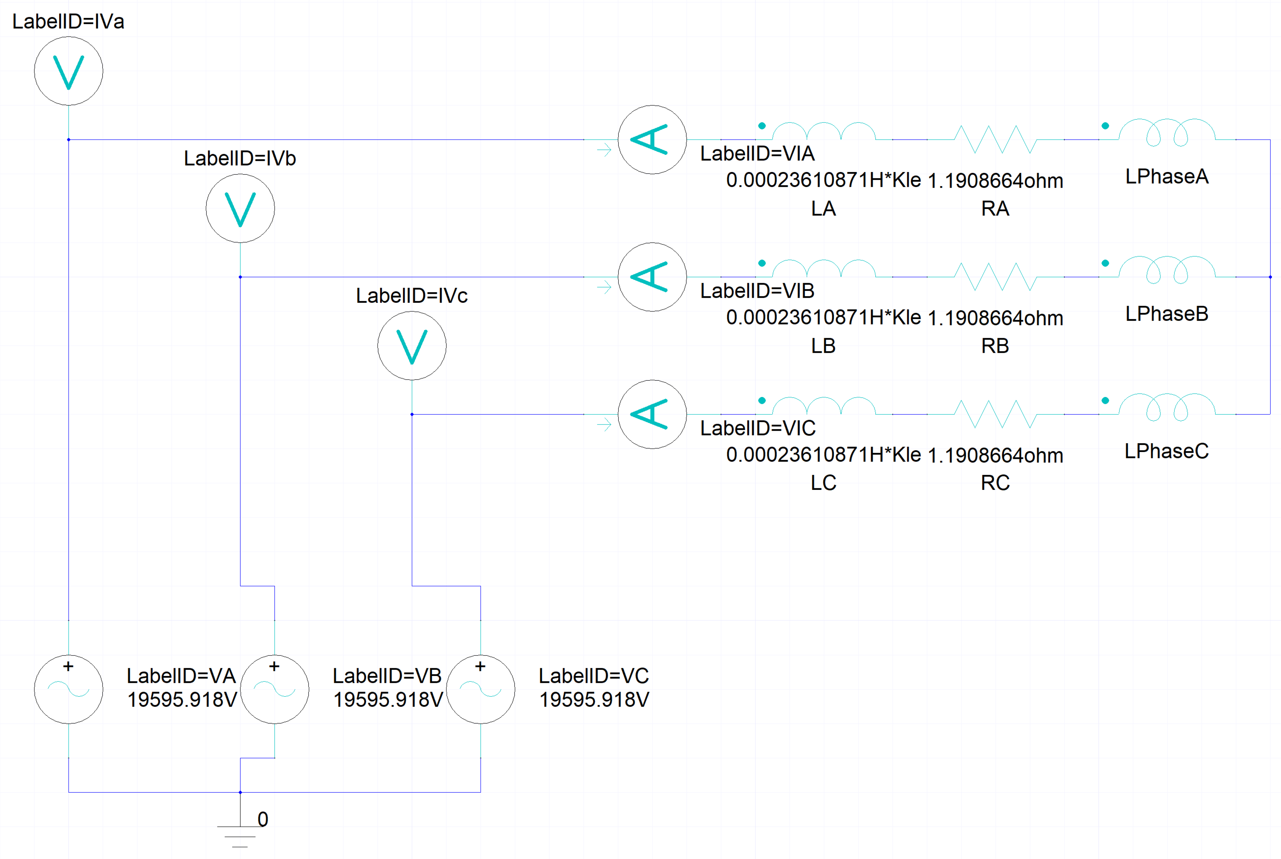
The coils in the rotor are excited by DC, and the current is given according to the test value under different working conditions. The excitation of stator windings uses an external circuit. The method of external circuit excitation can simulate different loads if change the load resistance. Besides, for the generator, the way of external circuit excitation can show the induction effect of rotating magnetic field on current more directly. The outer circuit consists of the terminal of the three-phase winding of the stator coil and the resistance inductor in series. Figure 5 shows the external circuit of stator windings.
The circuit in Figure 5 is a simplified version. L p h a s e A , L p h a s e B and L p h a s e C represent the three phases. The line voltages are measured by V a , V b and V c . The I a , I b and I c represent the line currents. The line voltage is 1.732 times the phase voltage respectively, while the line current is equal to the phase current, because of the Wye connection. The resistors R 1 , R 2 , R 3 and the inductance L 1 , L 2 , L 3 are used to simulate a real situation. The rated load condition of the load resistance R and inductance L is determined by
I N = P / ( 3 U N c o s ϕ )
Z = U N 3 I N
R = Z c o s ϕ
Z L = Z 2 R 2
L = Z L ω
where U N , P, I, Z, R, and L represent the rated voltage, the load of the generator, rated current, impedance, resistance and inductance, respectively. Adjusting the load impedance and inductance using the upper formula can simulate the case of different load conditions. Then, the current and electromagnetic field will be changed as the load changes under load conditions.

3.2. The Model of Rotor Eccentricity

The 2-D and 3-D electromagnetic fields of the generator is calculated. The results show that there is no difference in the distribution and values of the 2-D and 3-D electromagnetic fields. This section will show the distribution of the magnetic induction intensity of the motor, the distribution of the nodal forces and the variation pattern of the unbalanced magnetic pull. According to the hydro-generator installation standard, the deviation of the rotor center should not exceed 0.15 mm. In this paper, five deviation models of center deviation are established, which are 0.05 mm, 0.1 mm, 0.15 mm, 0.2 mm and 0.25 mm. Except for the rotor center deviation, other parameter settings are the same as in the first section of this chapter. Taking the model of 0.15 mm center deviation as an example in Figure 6, its mesh division is shown in Figure 7. The mesh at the air gap is properly refined to ensure calculation accuracy.

4. The Results of Electromagnetic Simulations

In this paper, a typical combination of rotor eccentricity is calculated. And from the results, we can obtain the mechanism of the influence of rotor eccentricity on the unbalanced magnetic pull of the generator.

4.1. Flux Density in the Air-Gap

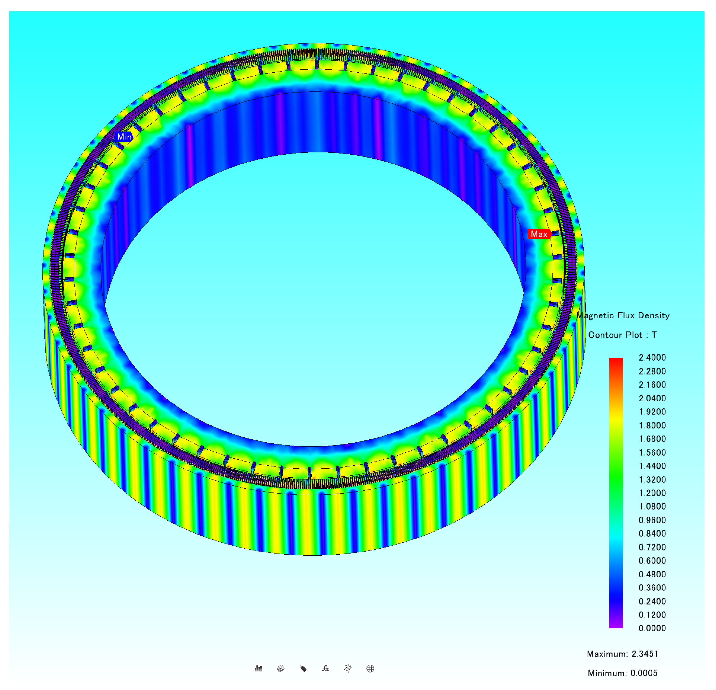
Rotor eccentricity can lead to uneven air-gap and consequently uneven magnetic field distribution. Consider the case of a rotor eccentric 0.15 mm motor operating at rated operating conditions. The following two graphs, Figure 8 and Figure 9, show the stator–rotor flux density and vector magnetic potential distribution of the motor in this case, respectively.
The magnetic field distribution of the motor in the eccentric case is not uniform, as can be seen from the flux density distribution diagram. However, this inhomogeneity is relatively insignificant due to the small eccentricity. The magnetic field shows a certain periodicity with the change of magnetic poles. The strong flux density is concentrated at the rotor magnetic poles.
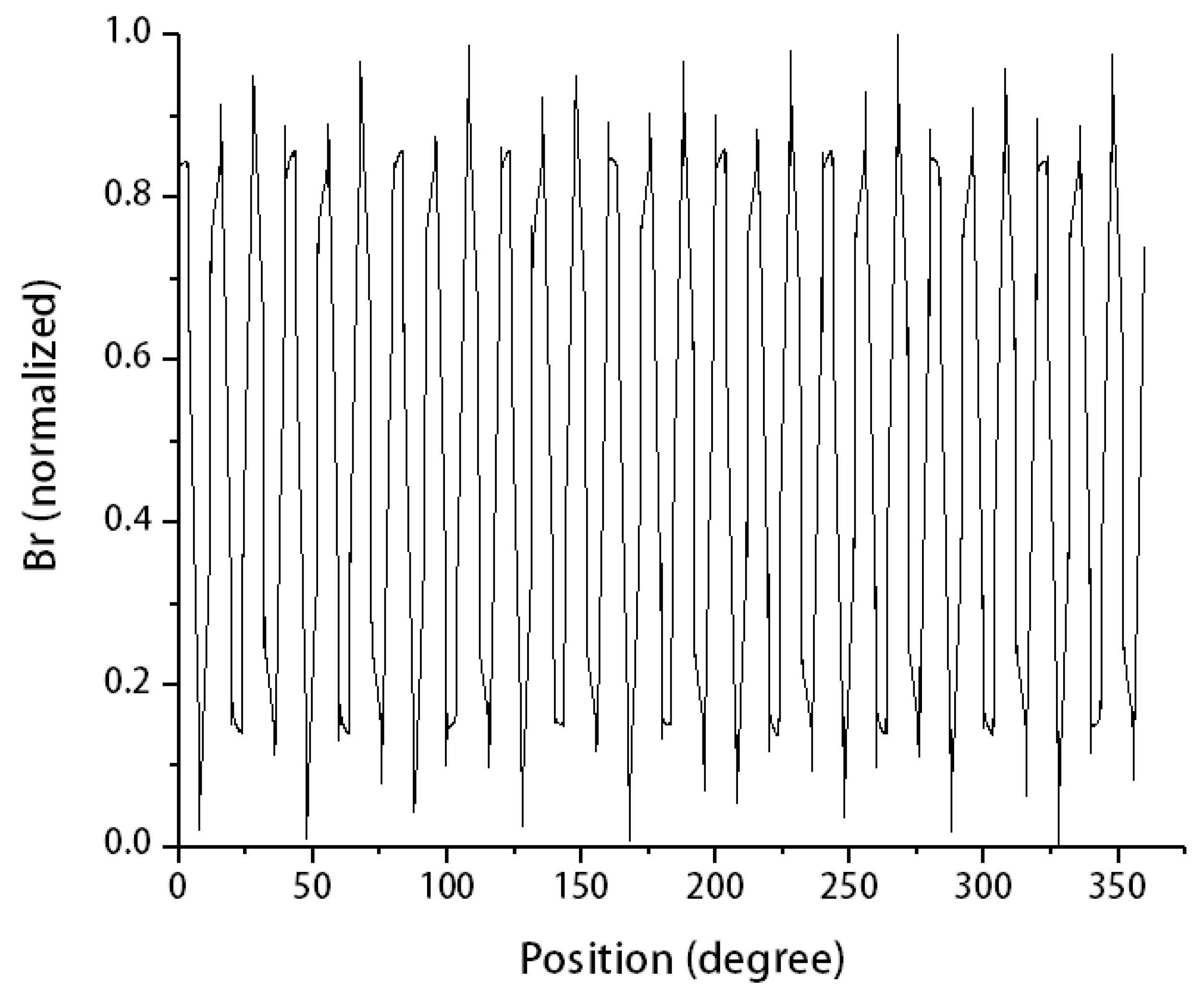
In order to specifically observe the variation of the numerical magnitude of the flux density in the air gap with the circumference, a circumferential line in the air gap is selected and the magnitude of the flux density on this line is obtained, as shown in Figure 10 and Figure 11. Since the tangential component of the flux density is small, it can be neglected. For the convenience of analysis and calculation, only the radial component of flux density is considered.
Figure 10 shows the distribution under full magnetic poles, and Figure 11 shows the distribution under a pair of magnetic poles. It can be seen from the plots that the magnetic induction intensity in the eccentric case is not uniformly distributed in the air gap, and the curve is distorted, and the original saddle shape is distorted. The peaks and valleys in the figure correspond to 27 pairs of magnetic poles, respectively. The small spikes on the individual crests and troughs correspond to the stator tooth cores.

4.2. Electromagnetic Force Density in the Air-Gap

The electromagnetic force is generated by the magnetic field and is closely related to the magnetic induction strength. When the magnetic induction strength is obtained, the electromagnetic force density can be calculated according to the formula for calculating the electromagnetic force per unit area.
f r = ( B r 2 B t 2 ) 2 μ 0 ( B r 2 ) 2 μ 0
f t = B r B t μ 0
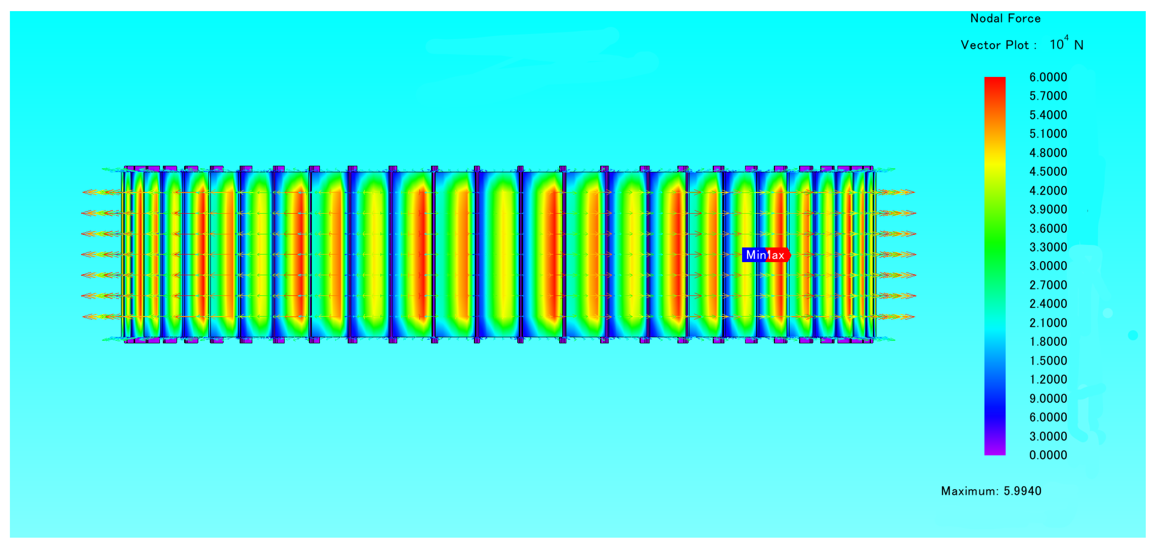
The electromagnetic force can be obtained by integrating the electromagnetic force density. Next, the electromagnetic force applied to the rotor part is calculated and analyzed. Figure 12 below shows the nodal force of the unbalanced magnetic pull on the rotor.
Figure 13 below shows the graph of the magnitude of unbalanced magnetic pull on the rotor with time for the cases of rotor eccentricity 0.05 mm, 0.1 mm, 0.15 mm, 0.2 mm and 0.25 mm. Figure 14 below shows the graph of the direction of the unbalanced magnetic pull on the rotor with time for the above eccentric cases. It is clear from Figure 13 that the magnitude of the unbalanced magnetic pull on the rotor increases as the eccentricity value increases, and the magnitude of the force fluctuation also increases. Looking at the curve of the unbalanced magnetic pull force on the rotor with time for a particular eccentricity case alone, it can be seen that the pattern of its vibration is related to the number of tooth slots.
As can be seen in Figure 14, the direction of the unbalanced magnetic pull rotates with the circumference and the rotational speed coincides with that of the rotor.
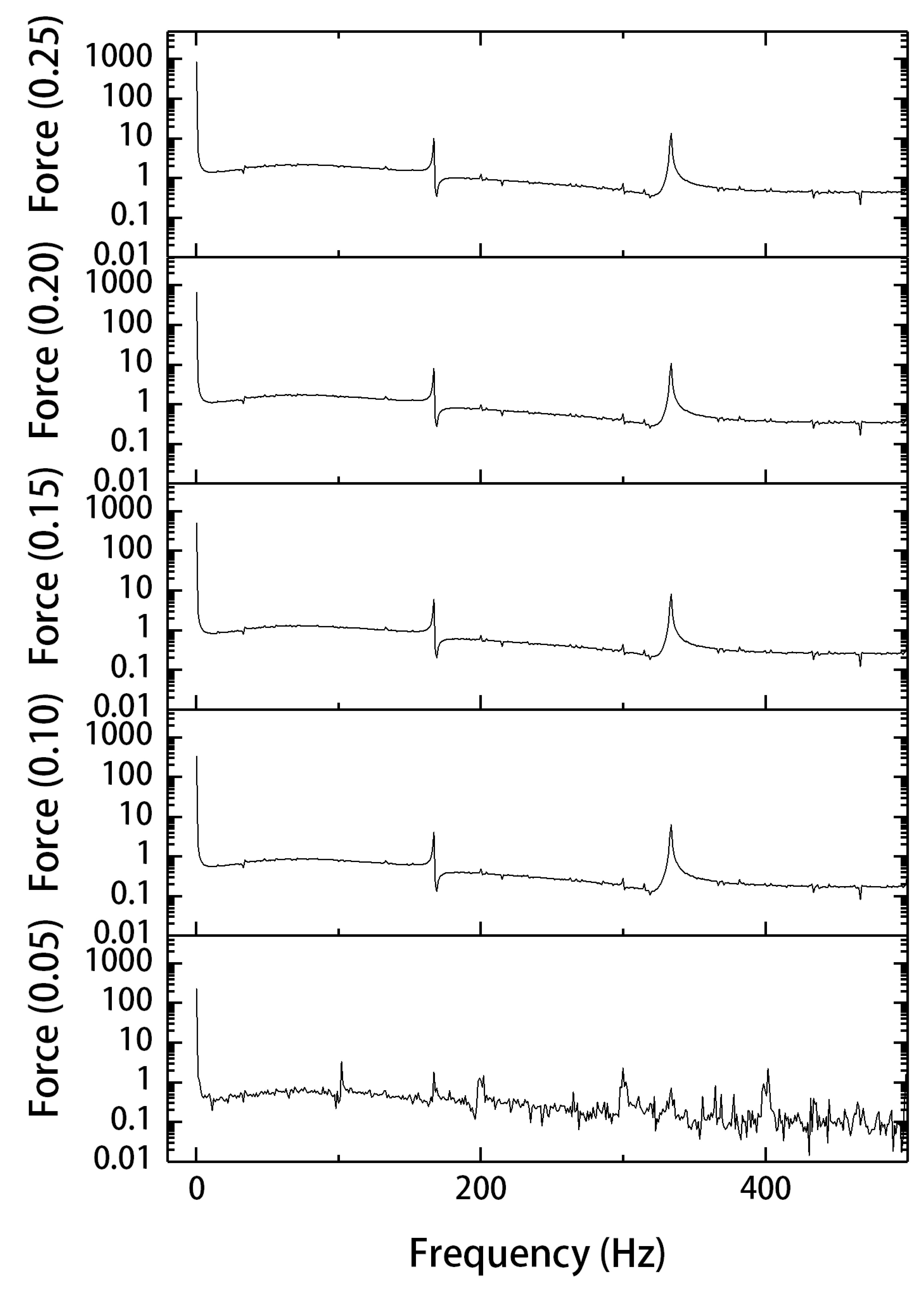
For further analysis, the unbalanced magnetic pull is FFT transformed to obtain Figure 15.
The frequency component of the unbalanced magnetic pull caused by the rotor eccentricity can be obtained from the following equation.
f e = f r N s l o t s N P a r a l l e l C i r c u i t
Since the calculation is based on the magnetic pull on the rotor, which is equivalent to standing on the rotor, the spectrum of magnetic pull is related to the stator core distribution, stator current and rotor speed. In addition to the DC component, we can see from Figure 15 that it exists mainly at 166 Hz and 332 Hz, which is consistent with the above equation. It can also be roughly seen from Figure 15 that the DC and the amplitude of each major harmonic of the unbalanced magnetic pull increase as the eccentricity value increases. This is consistent with the conventional perception.

4.3. The Influence of Different Eccentricity of Rotor

The DC component and the key harmonic component of the electromagnetic force are extracted and plotted with the rotor eccentricity value, as shown in Figure 16 and Figure 17. Figure 17 shows the normalization results of Figure 16.
From the figures, it can be concluded that:
  • Firstly, the harmonic component of the electromagnetic force is smaller compared to the DC component, and the difference between them is one order of magnitude.
  • Secondly, both the DC component and the key harmonic component of the unbalanced magnetic pull increase with the increase of the eccentricity value, and this variation relationship is nearly linear.

5. Conclusions

An accurate finite-element model of a 1000 MW hydro-generator, which considers the ununiform gap between the rotor and the stator, is presented and discussed in this paper. The conclusions of the research are listed below:
  • Both the space and time distributions of UMP will be changed by the elliptical deformation. The spatial distribution is related to the pole and stator tooth core distribution. And the frequency distribution is related to rotor speed and tooth slots.
  • As the eccentricity increases, the stator–rotor air-gap becomes more uneven. It affects the magnetic density distribution, which in turn leads to a change in the unbalanced magnetic pull spectrum. The general rule is that both the DC component and the key harmonic component of the unbalanced magnetic pull increase with the increase of the eccentricity value, and this variation relationship is nearly linear.
  • The measured eccentricity of the rotor of the hydro-generator unit installed with high precision is lower than 0.15 mm. The unbalanced magnetic pull and vibration caused by the rotor eccentricity are calculated to be very small and consistent with the field measurement.
Future studies will be carried out from a three-dimensional perspective, and the coupling calculation of electromagnetic field-thermal field-structural field will be added to further analyze the influence of deviation on vibration and deformation.

Author Contributions

Conceptualization, Z.W. and J.Z. (Jianwei Zhang); methodology, J.Z. (Jiwen Zhang) and G.C.; software, J.Z. (Jiwen Zhang); validation, J.Z. (Jianwei Zhang), X.H., G.C. and C.Y.; formal analysis, J.Z. (Jiwen Zhang); investigation, J.Z. (Jiwen Zhang) and C.Y.; resources, J.Z. (Jianwei Zhang), G.C. and C.Y.; data curation, J.Z. (Jiwen Zhang) and X.H.; writing—original draft preparation, J.Z. (Jiwen Zhang); writing—review and editing, J.Z. (Jiwen Zhang) and X.H.; visualization, J.Z. (Jiwen Zhang); supervision, Z.W.; project administration, X.H. and Z.W.; funding acquisition, Z.W. All authors have read and agreed to the published version of the manuscript.

Funding

This work was supported by National Natural Science Foundation of China (No.: 51876099).

Institutional Review Board Statement

Not applicable.

Informed Consent Statement

Not applicable.

Data Availability Statement

Not applicable.

Acknowledgments

The authors gratefully acknowledge the financial support of the project: “Research on the mechanism of shaft system dynamic performance change caused by installation deviation of giant hydro-generator units and the engineering applications” from Sinohydro Engineering Bureau 4 Co., LTD.

Conflicts of Interest

The authors declare no conflict of interest.

Abbreviations

The following abbreviations are used in this manuscript:
Abbreviations
DCdirect current
FEMfinite element method
UMPunbalanced magnetic pull
2-Dtwo-dimensional
3-Dthree-dimensional
FEfinite element
MSTmaxwell stress tensor
Nomenclature
ParametersDescription
A Vector magnetic potential (V · s · m 1 )
μ 0 Air magnetic permeability (H/m)
σ Electrical conductivity (S/m)
J 0 Surface current density of the excitation source (A· m 2 )
v Movement speed (m· s 1 )
J 0 z z-axis component of the surface current density (A· m 2 )
A z z-axis component of vector magnetic potential (V· s· m 1 )
v x x-axis component of movement speed (m· s 1 )
v y y-axis component of movement speed (m· s 1 )
JMoment of inertia (kg· m 2 )
λ damping coefficient
ω angular velocity (rad/s)
T e m electromagnetic torque (N· m)
T l o a d Load torque (N· m)
B Intensity of magnetic induction (T)
f m m Total magneto-motive force (N)
Λ Total air-gap permeance (m 1 )
F n The nth harmonic component of the magneto-motive force (N)
θ , β Angular position in the air gap (rad)
β Phase angle between stator and rotor magneto-motive force (N)
gAir-gap length (m)
g 0 Average value of air-gap length (m)
δ s n Air-gap permeance components caused by stator deformation
δ r m Air-gap permeance components caused by rotor deformation
α n Stator phase angle (rad)
α m Rotor phase angle (rad)
ω r Mechanical angular frequency (rad· s 1 )
Λ 0 Permeance of the air gap without deformations (m 1 )
Λ s Permeance of the air gap with static eccentricity (m 1 )
Λ s n Permeance of the air gap with stator deformation (m 1 )
Λ r m Permeance of the air gap with rotor deformation (m 1 )
σ n Radial force density (N· m 2 )
B n Tangential component of flux density (T)
B t Radial component of flux density (T)
FUnbalanced magnetic force (N)
F x x-axis unbalanced magnetic force (N)
F y y-axis unbalanced magnetic force (N)
LRotor length (m)
RRotor radius (m)
f e Frequence of UMP with rotor eccentricity (Hz)
f r Frequence of rotor rotation (Hz)
N s l o t s Numbers of the tooth slots of the stator
N P a r a l l e l C i r c u i t Numbers of the parallel circuit

References

  1. Dirani Merkhouf, A.; Giroux, A.-M.; Kedjar, B.; Al-Haddad, K. Impact of Real Air-Gap Nonuniformity on the Electromagnetic Forces of a Large Hydro-Generator. IEEE Trans. Ind. Electron. 2018, 65, 8464–8475. [Google Scholar] [CrossRef]
  2. Song, Z.; Liu, Y.; Guo, P.; Feng, J. Torsional Vibration Analysis of Hydro-Generator Set Considered Electromagnetic and Hydraulic Vibration Resources Coupling. Int. J. Precis. Eng. Manuf. 2018, 19, 939–945. [Google Scholar] [CrossRef]
  3. Zhou, J.; Peng, X.; Li, R.; Xu, Y.; Liu, H.; Chen, D. Experimental and Finite Element Analysis to Investigate the Vibration of Oblique-Stud Stator Frame in a Large Hydropower Generator Unit. Energies 2017, 10, 2175. [Google Scholar] [CrossRef] [Green Version]
  4. Verez, G.; Barakat, G.; Amara, Y. Influence of slots and rotor poles combinations on noise and vibrations of magnetic origins in ‘u’-core flux-switching permanent magnet machines. Prog. Electromagn. Res. B 2014, 61, 149–168. [Google Scholar] [CrossRef] [Green Version]
  5. Hu, Q.L.; Xiao, K.; Zhou, Z.T.; Fan, Z.N.; Yang, Y.; Bian, Z.Y.; Li, J.C.; Yao, B. 3D Transient Electromagnetic-Temperature Field Analysis of the Loss and Heat of the Damper Bars of a Large Tubular Hydro-Generator During Short Circuit Faults. IEEE Access 2020, 8, 135963–135974. [Google Scholar] [CrossRef]
  6. Wang, L.; Li, W. Assessment of the Stray Flux, Losses, and Temperature Rise in the End Region of a High-Power Turbogenerator Based on a Novel Frequency-Domain Model. IEEE Trans. Ind. Electron. 2018, 65, 4503–4513. [Google Scholar] [CrossRef]
  7. Jiang, H.C.; He, Y.L.; Tang, G.J.; Yuan, X.H. Electromagnetic Force and Mechanical Response of Turbo-Generator End Winding under Electromechanical Faults. Math. Probl. Eng. 2021, 2021, 9064254. [Google Scholar] [CrossRef]
  8. Wang, L.; Cheung, R.W.; Ma, Z.; Ruan, J.; Peng, Y. Finite-Element Analysis of Unbalanced Magnetic Pull in a Large Hydro-Generator Under Practical Operations. IEEE Trans. Magn. 2008, 44, 1558–1561. [Google Scholar] [CrossRef]
  9. Nasiri-Zar, I.R.; Toulabi, M.S.; Karami-Shahnani, A. Two-Segment Magnet Transverse Flux Ferrite PM Generator for Direct-Drive Wind Turbine Applications: Nonlinear 3-D MEC Modeling and Experimental Validation. IEEE Trans. Energy Convers. 2022, 37, 1834–1843. [Google Scholar]
  10. Nuzzo, S.; Galea, M.; Gerada, C.; Brown, N. Analysis, Modeling, and Design Considerations for the Excitation Systems of Synchronous Generators. IEEE Trans. Ind. Electron. 2018, 65, 2996–3007. [Google Scholar] [CrossRef]
  11. Xu, Y.; Zhao, D.; Wang, Y.; Ai, M. Electromagnetic Characteristics of Permanent Magnet Linear Generator (PMLG) Applied to Free-Piston Engine (FPE). IEEE Access 2019, 7, 48013–48023. [Google Scholar] [CrossRef]
  12. Zhu, S.; Liu, C.; Wang, K.; Zhou, Z.; Yu, J. Structure and Operating Performance of a Double Electrical Excitation Synchronous Generator With Embedded Brushless Synchronous Exciter Utilizing DC-Field Excitation. IEEE Trans. Energy Convers. 2022, 37, 50–64. [Google Scholar] [CrossRef]
  13. Li, Y.B.; Ho, S.L.; Fu, W.N.; Liu, W.Y. An interpolative finite element modeling and its starting process simulation of a large solid pole synchronous machine. IEEE Trans. Magn. 2009, 45, 4605–4608. [Google Scholar] [CrossRef]
  14. Mirimani, S.M.; Vahedi, A.; Marignetti, F.; Di Stefano, R. An online method for static eccentricity fault detection in axial flux machines. IEEE Trans. Ind. Electron. 2015, 62, 1931–1942. [Google Scholar] [CrossRef]
  15. Karlsson, M.; Aidanpää, J.O.; Perers, R.; Leijon, M. Rotor Dynamic Analysis of an Eccentric Hydropower Generator With Damper Winding for Reactive Load. J. Appl. Mech. 2007, 74, 1178–1186. [Google Scholar] [CrossRef]
  16. Li, R.; Li, C.; Peng, X.; Wei, W. Electromagnetic Vibration Simulation of a 250-MW Large Hydropower Generator with Rotor Eccentricity and Rotor Deformation. Energies 2017, 10, 2155. [Google Scholar] [CrossRef] [Green Version]
  17. Calleecharan, Y.; Aidanpaa, J.O. On the Dynamics of an Hydropower Generator Subjected to Unbalanced Magnetic Pull. In Proceedings of the IET 8th International Conference on Computation in Electromagnetics (CEM 2011), Wroclaw, Poland, 11–14 April 2011; pp. 50–51. [Google Scholar]
  18. Calleecharan, Y.; Jauregui, R.; Aidanpää, J.O. Estimating forces in mixed eccentricities motion from purely dynamic eccentric rotor centre motion in a hydropower generator and their validation against EM simulations. Balk. J. Electr. Comput. Eng. 2015, 3. [Google Scholar] [CrossRef]
  19. Ma, M.; Li, Y.; Wu, Y.; Dong, C. Multifield Calculation and Analysis of Excitation Winding Interturn Short Circuit Fault in Turbo-Generator. Energies 2018, 11, 2626. [Google Scholar] [CrossRef] [Green Version]
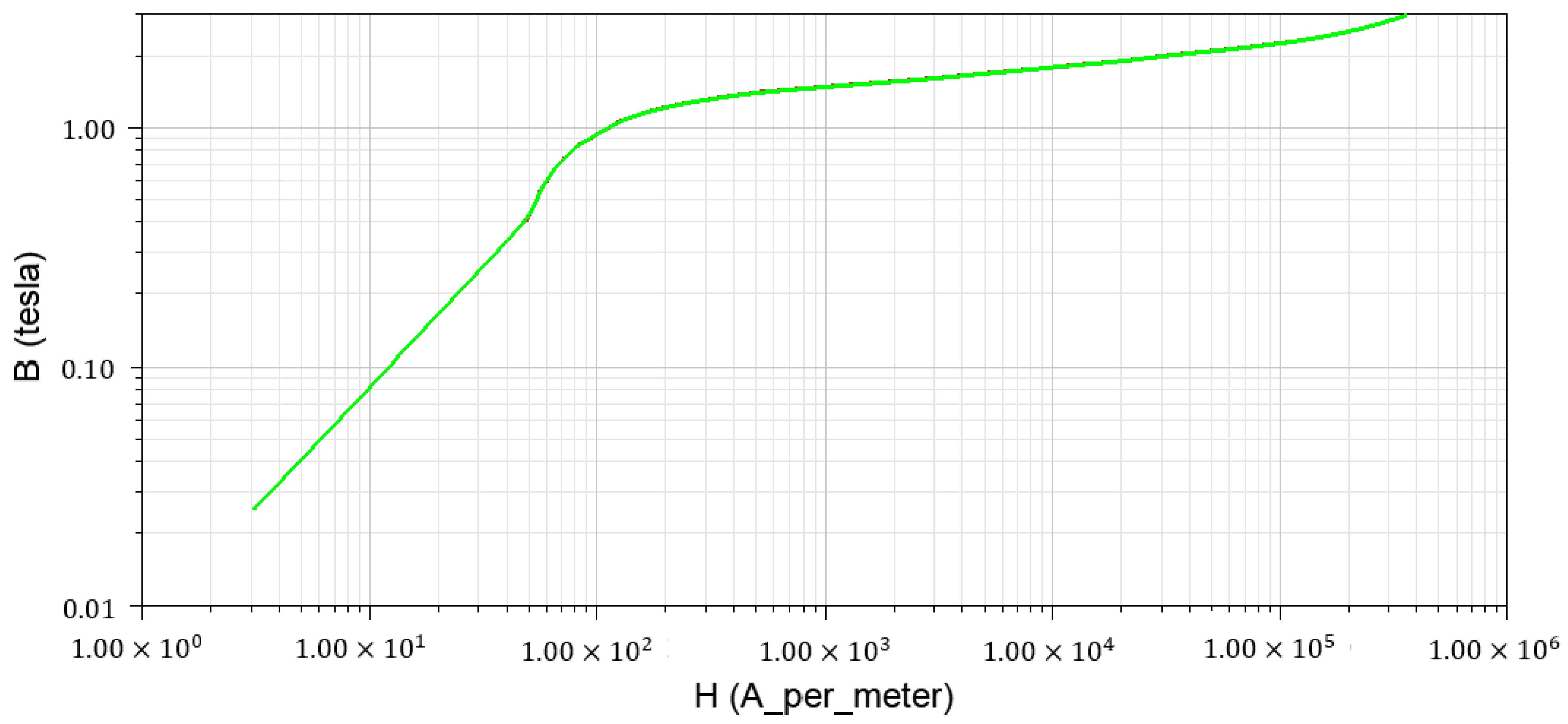
Figure 1. The magnetic nonlinearity of 50W250.
Processes 11 00899 g001
Figure 2. The magnetic nonlinearity of SXRE750.
Processes 11 00899 g002
Figure 3. The mesh of the hydro-generator. (main view).
Processes 11 00899 g003
Figure 4. The mesh of the hydro-generator. (top view).
Processes 11 00899 g004
Figure 5. The external circuit of stator windings.
Processes 11 00899 g005
Figure 6. The rotor eccentricity model with 0.15 mm deviation.
Processes 11 00899 g006
Figure 7. The mesh of the rotor eccentricity model with 0.15 mm deviation.
Processes 11 00899 g007
Figure 8. Magnetic induction intensity distribution map.
Processes 11 00899 g008
Figure 9. Vector magnetic potential map.
Processes 11 00899 g009
Figure 10. The distributions in space of radial flux density in air gap under 0.15 mm eccentricity. (whole model).
Processes 11 00899 g010
Figure 11. The distributions in space of radial flux density in air gap under 0.15 mm eccentricity. (one pole).
Processes 11 00899 g011
Figure 12. The nodal force of the unbalanced magnetic pull on the rotor.
Processes 11 00899 g012
Figure 13. The magnitude of unbalanced magnetic pull on the rotor with time. (normalized).
Processes 11 00899 g013
Figure 14. The direction of the unbalanced magnetic pull, varying with time.
Processes 11 00899 g014
Figure 15. FFT transformation of UMP.
Processes 11 00899 g015
Figure 16. The relationship between the UMP and eccentricity.
Processes 11 00899 g016
Figure 17. The relationship between normalized UMP and eccentricity.
Processes 11 00899 g017
Table 1. Basic parameters of the hydropower generator.
Parameters (Units)Values
Rated power (MW)1000
Rated power factor0.9
Number of poles54
Number of slots810
Winding connectionWye
Parallel branches9
Coil pitch14
Frequency50 Hz
Inner diameter of the stator17,500 mm
Outer diameter of the stator16,300 mm
Aair gap thickness49 mm
The armature winding end part extension120 mm
Disclaimer/Publisher’s Note: The statements, opinions and data contained in all publications are solely those of the individual author(s) and contributor(s) and not of MDPI and/or the editor(s). MDPI and/or the editor(s) disclaim responsibility for any injury to people or property resulting from any ideas, methods, instructions or products referred to in the content.