Abstract
The hydrogen cycle system, one of the main systems used for hydrogen fuel cells, has many advantages. It can improve the efficiency, the water capacity, and the management of thermal fuel cells. It can also enhance the safety of the system. Therefore, it is widely used in hydrogen fuel cell vehicles. We introduce the structure and principles of hydrogen cycle pumps, ejectors, and steam separators and analyze and summarize the advantages of the components, as well as reviewing the latest research progress and industrialization status of hydrogen cycle pumps and ejectors. The technical challenges in hydrogen circulation systems and the development direction of key technologies in the future are discussed. This paper aims to provide a reference for research concerning hydrogen energy storage application technology in hydrogen fuel cell systems.
1. An Introduction to the Background of Hydrogen Fuel Cells
With the rapid development of the world economy and rapid growth in the global population, there is increased human demand for energy day by day, while the use of traditional fossil fuels has led to serious environmental pollution and the greenhouse effect. At present, in order to cope with global energy changes, countries are seeking to move in the direction of “clean, low-carbon, safe and efficient” energy development. The energy revolution has become an irresistible trend. Hydrogen, which has a high calorific value and is clean and pollution-free after use, will become an important alternative energy source and can form another pillar of the renewable electricity energy transition by replacing coal, oil, natural gas, and traditional hydrogen in different economic sectors [1,2]. In addition, hydrogen is an energy carrier—its versatility will play a key role in the decarbonization process. For major civil and industrial applications, the role of hydrogen in decarbonizing “refractory” industries is about to come significantly to the fore [3,4].
In the field of transportation, hydrogen battery cars and hydrogen battery ships can be developed. The International Maritime Organization (IMO) has declared an initial strategy to reduce greenhouse gas (GHG) emissions from ships [5]. Bouman et al. [6] studied alternative fuels to reduce greenhouse gas emissions from ships. However, liquefied natural gas (LNG) ultimately fell short of the IMO requirements. Therefore, more environmentally friendly marine fuels, such as methanol, ammonia, and hydrogen should be used [7]. Japan’s “Green Growth Strategy” proposes that by 2050, all existing traditional fuel vessels will be converted into hydrogen, ammonia, LNG, and other low-carbon fuel powered vessels. Research and development and the popularization of hydrogen fuel cell systems and electric propulsion systems for close-range and small vessels is to be promoted. Wartsila, the global leader in marine engines, expects to launch an ammonia hybrid engine in 2021, a pure ammonia engine in 2023, and a pure hydrogen engine in 2025. Ahmed G. Elkafas et al. [8] consider the fuel cell systems applicable to the marine sector and provide a detailed analysis of the main characteristics of fuel cell systems, the available technology suppliers, international policies on fuel cells on board ships, and the possibility of applying fuel cell systems on different ship types. Chinese ships and other enterprises are also actively developing hydrogen–ammonia engines and hydrogen-fueled gas turbines. Fuel cell vehicles are still considered to be the ideal solution for future new energy vehicles because of their rapid air supply, lack of pollution, and high energy density [9,10].
In the field of aviation, the aviation industry emits more than 900 million tons of carbon dioxide every year. Hydrogen energy represents the primary means of developing low-carbon aviation [11]. Hydrogen can be combined with carbon dioxide to produce a “transition” fuel that does not require changes to existing aircraft infrastructure. Given the aviation sector’s low asset turnover, hydrogen fuels represent the main path to meaningful decarbonization of aviation by 2050. Currently, the top 10 airports in the world are exploring, or have already deployed, refueling infrastructure to aid transportation and logistics. For commuter and regional airliners, fuel cell propulsion is the most energy efficient, environmentally friendly, and economical option. For short-haul airliners, hybrid power (hydrogen combustion and fuel cells) may be the best solution. Small hydrogen-powered aircraft projects are on the rise in Europe and in the United States. For long-range airliners, synthetic fuels may be a more cost-effective solution to achieve decarbonizing benefits [12].
The 2021 Global Hydrogen Energy Assessment Report released by the International Energy Agency (IEA) points out that hydrogen will play a significant part in the global energy transformation. By 2030, the global hydrogen demand for terminal applications of hydrogen energy will reach about 90 million tons. According to the International Hydrogen Energy Commission, hydrogen energy is anticipated to account for 18% of the global energy consumption structure in 2050, which will reduce carbon dioxide emissions by 6 billion tons [13,14]. Hydrogen, as a low carbon, environment-friendly, and safe energy carrier that is able to play a critical part in the energy system is receiving increasing attention. It is widely regarded as an option for decarbonization in various industries, used in its pure form or converted to hydrogen-based fuels, like synthetic methane, methanol, or ammonia, which can be reserved, burned, or combined in chemical reactions [15].
Since 1998, when the California zero emission vehicles (ZEVs) project failed, great progress has been made. We now see proton exchange membrane fuel cell (PEMFC) ZEVs used by several car manufacturers (e.g., Hyundai, Toyota, Honda), as well as many European Union companies (e.g., air liquefaction, air products companies, Linde) installing hydrogenation stations, which are increasing in cities. Green hydrogen fuel cells are still being used to power buildings. It is a revolution approaching commercial reality in multiple industries that are moving from using fossil hydrogen to green hydrogen, as well as from combustion devices to PEMFC. Therefore, the study of hydrogen energy has grown rapidly, and scholars around the world have explored its wide application with hydrogen energy as the core. The experimental results of Zhang et al. [16] indicate that when a magnetic field of 260 mT is loaded onto the cathode for fuel cells with parallel, wave, and M-type flow fields, the maximum power density (MPD) increases by 55%, 23.9%, and 23.22%, respectively. The utilization of magnetic fields can enhance the performance of PEMFCs under operating conditions. A novel cathode flow field plate with additional tapered Qblique Fin (OF) channels was proposed by Zhu et al. [17] for air-cooled PEMFCs to promote their heat dissipation and output power. Zhang et al. [18] investigated membrane electrode assembly (MEA). The problem of stress concentration on the membrane at the joint area was solved by introducing a double-layer frame structure to limit membrane deformation. Ahmadi et al. [19] focused on developing an analytical and mathematics-based model to predict the transport and output performance of PEMFCs at different penetration (diffusion) velocities from the bottom of flow channels. The movement, distribution, and diffusion of reactants and products inside the chamber are significantly influenced by the geometry and configuration of the flow field [20,21]. Ma et al. [22] conducted a comprehensive evaluation and comparison of different hybrid systems, such as PEFMCs and solid oxide fuel cells, from the perspectives of system configuration, technical specifications, energy management strategies, and experimental verification, and summarized the design suggestions for high-performance fuel cell hybrid power systems. Jose J. de-Troya et al. [23] studied the advantages and problems of fuel cell types, identifying the emission reduction potential of each type. Xing et al. [24] summarized the types, layouts and characteristics of fuel cell modules based on existing applications, and analyzed the challenges faced by fuel cell systems in terms of power capacity, safety, durability, and cost. Bai et al. [25] investigated the open-cathode PEMFC power system. In this study, two versions of open-cathode fuel cell stacks were developed, and performance and stability tests were conducted under various operating conditions. Additionally, tests were carried out with different carbon paper materials to find a balance between performance and stability.
As shown in Figure 1, the hydrogen fuel is continuously replenished, the electrochemical reaction continues, and the continuous current drives the load. As can be seen from the above reaction type, it is pollution-free to the environment, and the whole process does not produce harmful substances. Moreover, the power generating efficiency of the hydrogen fuel cell is quite high, which is determined by the conversion characteristics of the fuel cell. Without the intermediate conversion of heat energy and mechanical energy, it is directly converted from chemical energy to electric energy, which improves the efficiency.
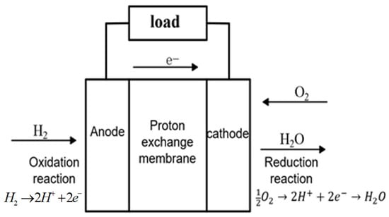
Figure 1.
Operating principle of PEMFC.
Hydrogen-driven PEMFCs are widely considered to represent the most promising and appealing candidate for EV power owing to their advantages, such as high efficiency, zero emissions, fast start, low operating temperature, and high energy density [26,27,28]. The hydrogen circulation system is mainly composed of a hydrogen fuel cell stack, a steam separator, a hydrogen circulating pump, an ejector, a H2 cylinder, and other modules. As shown in Figure 2, a classic PEMFC system is used in fuel cell vehicles. In some fuel cell systems, the hydrogen recovery assembly delivers excess unconsumed hydrogen from the anode to the fuel cell stack inlet for recovery to save fuel and to improve efficiency.
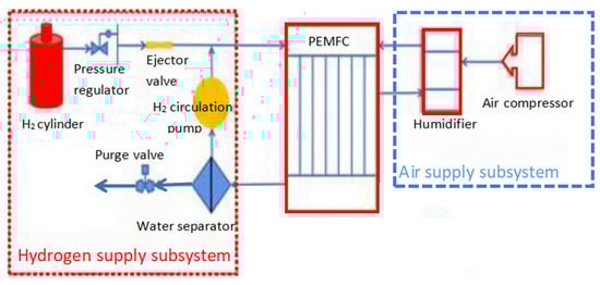
Figure 2.
Schematic drawing of a PEMFC system for fuel cell vehicles.
In terms of hydrogen cycle system solutions, there have long been different technical routes used in industry. At present, the main technical routes are use of a single hydrogen circulating pump mode and a parallel hydrogen circulating pump and ejector mode.
Fu et al. [29] used different sedimentation rates and filtration rates for short carbon fibers (CFs) as well as carbon nanotubes (CNTs). A simple gas diffusion layer (GDL) with three functional layers was successfully developed, and the thickness of the GDL was effectively controlled to be of 50 to 200 μm thickness. Zhang et al. [30] used a porous medium method to consider the heterogeneous airflow distribution in a fuel cell stack under the compression of different gas distribution layers (GDL) and optimized a single-channel electrochemical performance model. Under 10% GDL compression, the maximum and minimum velocities of various channels in the anode flow field differed by 5%. Jarry [31] studied the potential influence of high-frequency current ripples (HFCRs) on the aging of HT-PEMFCs and demonstrated that HFCR did not accelerate the degradation of HT-PEMFC single cells. PEMFCs are not commonly employed commercially because of major barriers with regard to durability and cost. To address this, scientists are searching for other approaches which may improve the durability and cut the costs of fuel cell systems, including developing low-cost electrode materials and designing high-performance components. Yu et al. [32] designed 17 major hydrogen energy pathways for fuel cell vehicles in China to evaluate their cost, environmental impact, and environmental efficiency. The results showed that increase in the use of renewable energy will lead to higher environmental efficiency of hydrogen electrolysis in the total electricity generation. Thus, the hydrogen route for renewable energy may be the most cost-effective approach, reducing the cost of circular energy. Because the utilization rate of hydrogen in a fuel cell stack is low, there will always be unreacted hydrogen discharged from the outlet with the products. Therefore, it is essential to use the hydrogen circulation system to process, recycle, and reuse the unreacted hydrogen to avoid waste of hydrogen, as well as to increase the utilization rate of hydrogen. In addition, the system requires to prevent the risk of unreacted hydrogen gas exploding during the discharge process. With breakthroughs in hydrogen energy technology and the wide range of applications of hydrogen energy, use of hydrogen energy in industry is likely to undergo a major upsurge. In order to provide sufficient hydrogen for fuel cells, as well as to increase the utilization rate of hydrogen, the design of hydrogen circulation systems is currently a major research ‘hotspot’.
This paper mainly analyzes typical hydrogen circulation systems and the primary internal modules, summarizing the principles underpinning various devices, including the hydrogen circulation pump, the ejector, and the water separator. It also provides a review of the latest research results, the present situation, and the technical difficulties that require to be addressed. Finally, it discusses the challenges in the future development process and direction and puts forward effective suggestions for each module where problems remain, providing a reference for others.
2. An Overview of the Hydrogen Fuel Cell Power Standard and Specification
With increase in economic globalization, the standards for certain machinery parts, industry regulations, production requirements, and other aspects are gradually being unified. Standard specifications are now extensively used to regulate the production and use of hydrogen fuel cells, which is contributing to their widespread adoption. Table 1 lists some domestic and foreign standards related to hydrogen fuel cells, including those applied to hydrogen-fuel-cell-powered ships. The standard specifications related to hydrogen fuel cell power mainly deal with fuel cells, the hydrogen supply and storage systems, and to hydrogen safety. The relevant standards and specifications for hydrogen-fuel-cell-powered ships mostly are general, and provide a reference and guidance for the relevant technical standards and specifications of hydrogen fuel cell vehicles.

Table 1.
Standards related to hydrogen fuel cell power [33,34,35,36,37,38,39].
The ABS Marine and Offshore Fuel Cell Power System Application Guide covers all types of fuel cells, with a focus on the use of fuel cell systems in new and retrofit projects, as well as the deployment of propulsion and auxiliary systems, and ensuring the safety of the system. In this guide, the design requirements of fuel cells are specified. In addition, the functions and monitoring requirements of the fuel cell control, monitoring, and safety systems are clarified [40]. There are many other similar criteria. ISO 23273:2013 [41], an international standard that specifies many requirements for hydrogen safety protection and human protection for fuel cell vehicles inside and outside the vehicle, focuses on the condition of the vehicle during normal operation and the condition of a single point of failure of the vehicle, outlining the specific requirements. The GTR 13 regulation, which is the foundational regulation for fuel cell safety, applies to hydrogen systems with a nominal working pressure not exceeding 70 MPa and a maximum filling pressure of 1.25 times the nominal working pressure. This regulation specifies the requirements for hydrogen leakage, emissions, and alarm failure under normal use and collision conditions, and specifies how to achieve integrity of the system and the specific test methods to be used. The SAE J2578 standard [42], which specifies safety guidelines and methods for fuel cell vehicles, puts forward special requirements for the integration of hydrogen fuel cell systems into a vehicle. The standard has specific requirements for the integrity of the fuel cell system, and for addressing flooding, fail-safe shutdown, and potential hazards in the vehicle cabin.
3. An Introduction to the Hydrogen Circulation System
Before the birth of the hydrogen circulation system, the supply mode used for hydrogen was mainly direct line circulation and the dead-end mode [43]. Figure 3a presents a direct discharge cycle mode. This mode directly discharges unreacted hydrogen with safety risks that can lead to hydrogen explosion. Therefore, in 2001, some scholars proposed the dead model, as shown in Figure 3b. A purge solenoid valve is installed at the anode outlet to leave part of the hydrogen in the reaction area to enhance the utilization efficiency of the hydrogen. However, over time, the qualitative gas and the liquid water generated by the reaction diffuse to the anode area through the proton exchange membrane and accumulate, blocking the gas channel, resulting in the hydrogen being unable to effectively contact the catalyst, with a consequent battery voltage drop. Subsequently, scholars began to explore hydrogen recycling patterns, aiming to reduce hydrogen consumption, to reduce safety risks, and to extend battery life, as shown in Figure 3c–f.
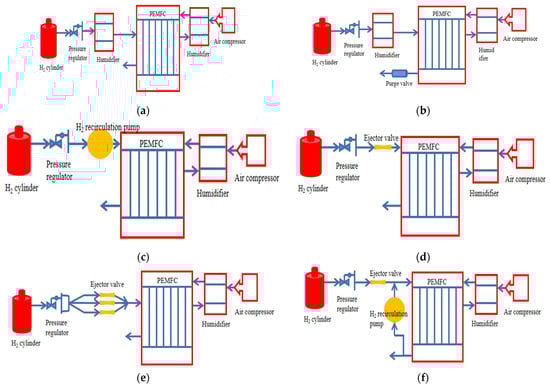
Figure 3.
(a) Rectangular circulation pattern; (b) Dead-end mode; (c–f) Hydrogen recycling pattern.
Neither the direct flow pattern nor the dead-end pattern met researchers’ expectations. In order to improve hydrogen utilization, by humidifying the intake [44,45] and improving the output characteristics of the reactor, researchers developed hydrogen recirculation structures enabling recycling of unreacted hydrogen and water at the fuel cell reactor outlet to the reactor inlet [46].
3.1. An Introduction to the Single Hydrogen Circulating Pump Scheme
The transfer of hydrogen that is not involved in the reaction at the anode of the cell is the function of the hydrogen cycle pump [47]. Hydrogen is discharged from the anode port and enters the hydrogen circulation pump after passing through the soda water separator, as shown in Figure 4.
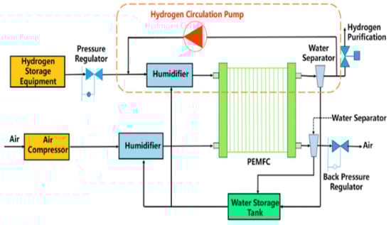
Figure 4.
Schematic diagram of fuel cell hydrogen circulation system [47].
Wang et al. [48] developed a car with a five-kilowatt proton-exchange membrane battery and proposed the use of a hydrogen cycle mode to improve fuel utilization. The FCHV-4 fuel cell vehicle was developed by the Toyota Motor Company [49] and a recycling scheme was proposed using a single hydrogen circulating pump. A major feature of this scheme is to control the circulation amount in real time through the rate of the hydrogen pump in order to achieve reflux and real-time control under any working conditions. Dongfeng Motor [50] published a patent CN111613815A, which proposes a fuel cell hydrogen circulation system and control method. By placing a pressure sensor and humidity sensor at the entrance of the fuel cell anode, the target speed of the hydrogen circulating pump is controlled.
The hydrogen pump power is affected by changes in the reactor power and the insulation efficiency. Under the same insulation efficiency, the hydrogen pump power drops when the reactor power decreases. At the same time, with a high-power hydrogen pump, the power change gradient is larger, and the change in low power is smaller. This is because the low power reactor stoichiometric ratio is larger, which causes the hydrogen circulation flow reduction to be smaller. In addition, hydrogen circulating pumps have other obvious disadvantages, including the following: (1) The hydrogen circulating pump can freeze at low temperature, resulting in the system being unable to start; (2) the noise can be too loud, which seriously affects the customer’s use experience; and (3) hydrogen pump research and development costs are high.
3.2. An Introduction to the Single-Ejector Scheme
However, hydrogen circulating pumps also face the problems of complex structure, high cost, large volume, high power consumption, significant noise, and poor environmental adaptability, which restrict the integration and application of hydrogen circulating pumps in fuel cell engines. Moreover, with the improvement in fuel cells towards high power, the requirements for components are becoming increasingly demanding. For example, when the working pressure gradually increases to 200~300 kPa, systems with high output power and high working pressure require to improve the performance of the hydrogen circulating pump in the high pressure ratio. To satisfy the requirement, scholars have proposed use of an ejector instead of a hydrogen circulating pump.
Figure 5 presents the working principle of a pilot-driven hydrogen recirculation system. The dry hydrogen reserved in the high-pressure tank is conveyed to the main nozzle of the ejector. Afterwards, the primary flow forms a low-pressure area at the nozzle outlet on account of the acceleration and pressure drop process in the nozzle, which can improve its capability to entrain the unreacted hydrogen and water vapor at the anode outlet, namely, the secondary flow. Finally, unreacted hydrogen and water vapor are mixed and flow through the diffuser of the ejector and then into the anode port.
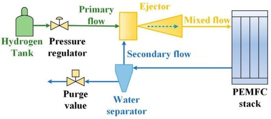
Figure 5.
Process flow diagram of the overall fuel cell system [51].
The Honda Motor Company [52] uses a two-stage variable nozzle ejector to control the hydrogen cycle in the FCX Clarity fuel cell vehicle (a hydrogen fuel cell car from Honda). The structure of the hydrogen supply system is exhibited in Figure 6. The NEXO fuel cell vehicle developed by the Hyundai Motor Company (Seoul, Republic of Korea) [53] adopts an integrated design scheme including a proportional valve and ejector. The ejector is a fixed diameter nozzle. The primary flow pressure of the ejector is adjusted through the proportional valve to meet the requirements of hydrogen circulation under different working conditions. The Wuhan Grove Hydrogen Automobile Co. (Wuhan, China) [54] published a patent CN112563537A, specifying an anode outlet and the setting up of a buffer tank, with water vapor separation occurring through ejector recycling. When the reactor power is small, the controller controls the upstream electromagnetic valve in the form of pulse open and closed, which makes full use of the hydrogen in the buffer tank and solves the problem of the ejector when the low power casting effect is poor.
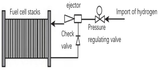
Figure 6.
Schematic diagram of Honda FCX Clarity Hydrogen [52].
The study shows that the greater the increase in the mixing segment diameter, the larger the hydrogen cycle ratio that the ejector can achieve at high power, but the hydrogen cycle ratio at low power decreases. This is because at high power, the primary flow of the primary current is larger, and the flow area occupied by the primary flow in the mixed cavity is larger, so that the flow area of the secondary flow is relatively reduced. Therefore, only a larger mixing section diameter enables the secondary flow to have a sufficient circulation area to produce a larger secondary flow rate. At present, the application of an ejector in the system is not very advanced—it is difficult to control the low load condition and the high load condition at the same time, so there are significant limitations in its range of use.
3.3. A Review on the Multi-Purpose Scheme
The circulation systems of single ejectors have progressively failed to meet people’s demands for performance, thus circulation systems using multi-ejectors have begun to be considered, as shown in Figure 3e.
As shown in Figure 7, for the American DTI company, Brian James et al. [55] developed a system design for an 80 kW vehicle fuel cell. Yang et al. [56] disclosed a patent CN113130941A, which involved the use of two ejectors to meet the requirements of hydrogen supply and hydrogen return at different flow rates. Figure 8 presents a schematic diagram of the dual ejector hydrogen supply system. The maximum and minimum values of the hydrogen pressure and flow rate are obtained according to the output power variation range of the fuel cell system under different operating conditions. Compared with a single ejector system, the dual-ejector scheme broadens the effective pilot range and improves the reactor performance, but increases the system complexity and control requirements.
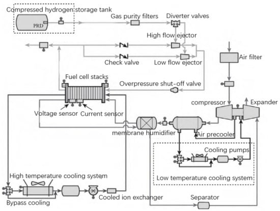
Figure 7.
System design drawing of 80 kW automobile fuel cell [55].
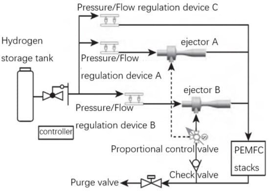
Figure 8.
Schematic diagram of dual ejector hydrogen supply system [56].
3.4. A Review of the Series and Parallel Connection Schemes of Ejector and Hydrogen Circulating Pumps
After a period of research, scholars found that when the reactor power is between 80 kW and 200 kW, only an introduction tor can meet the cycle requirements. When the reactor power is below 80 kW, the ejector cannot emit enough circulating gas. Therefore, a scheme involving parallel use of an ejector device and a hydrogen circulation pump was proposed to make up for the deficiency of a single component. The pumping pressure of the ejector and the hydrogen pump are the same in the parallel mode. The two pumps affect the flow rate differently to enable the total circulating flow rate to meet the demand, that is, the parallel mode of the ejector and the hydrogen pump are characterized by an “equal voltage rise and a divided flow rate”, as shown in Figure 3f. Researchers at the Argonne Laboratory [57] proposed a fuel cell system using a hydrogen circulating pump and ejector. When the actual hydrogen circulating flow is less than 25% of the rated flow, the hydrogen circulation pump is used, as shown in Figure 9.
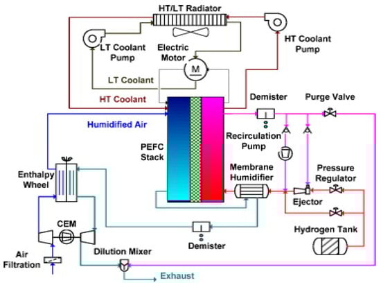
Figure 9.
Schematic diagram of the parallel scheme of ejector and hydrogen circulation pump [57].
The Toyota Motor Company [58,59] began publicly selling the hydrogen fuel cell car Mirai, which used the Toyota fuel cell system, as shown in Figure 10. The system uses a hydrogen circulating pump and three ejectors in parallel to enable recirculation of the anode hydrogen and hydrogen self-humidification. This is the first fuel cell system without external humidification.
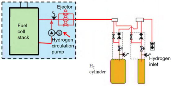
Figure 10.
Schematic diagram of the Mirai fuel cell system [58].
Li et al. [60] published a patent CN210224185U, which proposed a scheme involving the parallel setting of an ejector and a hydrogen circulating pump. When the fuel cell is running at high power, the hydrogen circulation pump is turned off and the hydrogen circulation is conducted through the ejector only. When the fuel cell is running at low power, the hydrogen circulation pump is opened for the hydrogen circulation to ensure that the hydrogen supply circulation device meets the emission requirements of the fuel cell under both low-power and high-power working conditions at the same time.
Xing of the Yantai Dongde Industrial Co., Ltd. [61] disclosed a patent CN112864420A, which proposed a design scheme involving integration of a hydrogen circulation pump and an ejector, as shown in Figure 11. The air inlet of the hydrogen circulation pump is connected to the low-pressure area of the ejector, and the air outlet of the hydrogen circulation pump is connected to the high-pressure area. The hydrogen directly enters the hydrogen circulation pump. Compared with the parallel scheme of the traditional hydrogen circulation pump and the hydrogen circulation pump, the transmission distance is short, the pipeline loss is less, and the system is more compact.
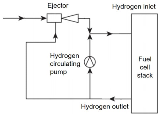
Figure 11.
System diagram of ejector and hydrogen circulation pump set in parallel [61].
The ejector and hydrogen pump can also be used in series, as shown in Figure 12. According to the working characteristics of the ejector, under the same primary flow, reducing the pressure rise can increase the ejection flow, so the hydrogen pump is used in series to reduce the pressure rise of the ejector. The hydrogen pump and the ejector successively pump the same flow of circulating gas, so that the total pressure rise of both systems is equal to the pressure lost by the hydrogen circulation system. Therefore, in contrast to the parallel mode, the series mode is characterized by “equal flow rate, partial pressure rise”.
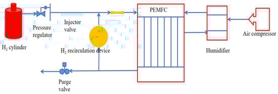
Figure 12.
Ejector and hydrogen circulating pump in series mode.
The characteristics of the parallel mode are that the working pressure of the ejector and the hydrogen pump is the same, and the use of the hydrogen pump for the ejector bears part of the flow that cannot be launched. The series mode is characterized by the same working flow of the two. The function of the hydrogen pump is to bear part of the pressure for the ejector and to reduce the pressure rise borne by the ejector in order to increase the ejection flow. Therefore, the function of the ejector and the hydrogen pump is to supercharge the circulation gas with a certain flow rate. The flow rate and the pressure rise are the two key factors affecting the hydrogen circulation device.
3.5. An Introduction to the Effect of the Hydrogen Circulation System Structure on PEMFC Performance
As mentioned above, the hydrogen circulation system of an ejector and a hydrogen circulation pump has its own characteristics. The hydrogen circulating system based on a hydrogen circulating pump has the advantages of applicability in all working conditions, active adjustment, response speed, etc., and has received extensive attention from both scholars and the market, with the Toyota Mirai single circulating pump system being a representative example. However, the hydrogen circulation pump produces vibration and noise during the working process, which reduces comfort, but in addition, its power consumption ratio reaches about 15% of the fuel cell power [62], which greatly reduces the effective output efficiency of the fuel cell. In addition, the large volume and heavy weight of the hydrogen circulation pump constitute the main volume and mass in the hydrogen fuel cell auxiliary system. As a pure mechanical structure with no moving parts, the ejector has a natural advantage in energy consumption, so the volume can be one-third of the hydrogen cycle system, and the cost half that of a hydrogen cycle pump. An ejector, under medium to high load conditions, has a good response profile, but under low negative cut conditions, especially under small flow operation conditions, its ejection coefficient is low, and it cannot reflux the ejected hydrogen. A comparison of the two schemes is shown in Table 2.
Table 2.
Comparison of two schemes based on an ejector and a hydrogen circulating pump.
For hydrogen cycle systems containing only an ejector, the working performance of the single-nozzle ejector is poor because the diameter of the single nozzle is relatively large and is unable to generate enough dynamic pressure. Deviation of the nozzle will affect the consistency of the flow field, which will lead to a decline in the ejector enrolling capacity. When the number of nozzles is more than one, when the primary flow pressure increases from 550 kPa to 650 kPa [63], under the same flow pressure, the recirculation ratio of a multi-nozzle ejector is greater than that of a single-nozzle ejector. There should not be too many nozzles, otherwise, in the case of only one nozzle in the ejector class, more vortices will be generated, resulting in more energy loss, so it cannot work normally.
4. An Introduction to the Hydrogen Circulating Pump
A hydrogen circulating pump is a kind of circulating pump, so named because it is mainly used in the hydrogen circulation system. In a solid oxide fuel cell (SOFC), the circulating pump is mainly used in the anode tail gas circulation system. The hydrogen circulating pump is a vital part of the hydrogen circulation system that can provide stable hydrogen circulation for the anode area of the battery, increase the hydrogen utilization rate of the fuel cell system, and play a very important role in the stable as well as reliable operation of the fuel cell system.
4.1. An Overview of the Claw Hydrogen Circulation Pump
A hydrogen gas pump for hydrogen fuel cell vehicles, the claw hydrogen circulation pump, has the characteristics of strong durability and a simple and compact structure. It mainly consists of two rotors, inlet and outlet pipes, the housing, and other accessories, which through the claw rotor rotation achieve suction, compression, exhaust, and other processes to drive the fluid. Compared with Roots pumps without built-in compression, they also guarantee high efficiency at relatively high pressures. However, claw hydrogen circulation pumps exhibit problems, such as poor seal shape, noise, and vibration, and are easy to deform due to contact and friction between the rotors [64]. If a wide range of working conditions are required, better claw teeth need to be designed to establish a balance between the compression ratio and performance. A kind of sharp-claw rotor and a smooth-claw rotor were proposed by Wang et al. [65], and the contour equation was derived. The smooth claw rotor improved the handling and mechanical properties. Gu et al. [66] used the Taguchi method and analysis of variance (ANOVA) to conduct computational fluid dynamics (CFD) simulations of six factors in the unabiding flow field of a dynamic grid claw pump with a structure. They established a three-dimensional model of a claw hydrogen circulating pump to determine the near-optimal conditions of high volumetric efficiency and low shaft power and used the simulated data to train the neural network. The ability of the neural network to accurately predict pump performance was verified by experiment. The 3D model is illustrated in Figure 13.
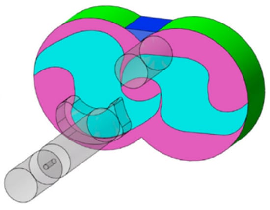
Figure 13.
Claw hydrogen circulation pump model [66].
A three-dimensional mathematical model was established by Kairui Dong [67,68] for a hydrogen circulating pump. They calculated the meshing clearance distribution between two rotors at different angles, the circumferential clearance distribution at different positions, and considered the influence of the suction pressure, discharge pressure, rotational speed, and clearance on the volumetric efficiency, providing theoretical guidance for the research as well as structural optimization of the hydrogen circulating pump. In order to reduce gas leakage, a new type of pinion rotor was proposed by Pan et al. [69], and a geometric model of the pinion rotor was established. The study showed that the gas leakage rate between the new gear claw rotor was clearly reduced, and the volumetric efficiency was effectively improved when comparing the traditional claw rotor to the new gear claw rotor.
The claw type hydrogen circulating pump has obvious thermal deformation problems under working conditions. The air temperature depends on the air temperature around the pump housing. The two rotors are alternately exposed to hot and cold gas. The average temperature of the hydrogen is used as the room temperature. The air temperature is consistent with the air temperature around the pump housing. The fluid temperature in the cavity is higher than the motor temperature. The pump housing heat transfer fin reaches maximum deformation. As the end face of the motor gets closer and closer, the deformation in the circular direction of the pump cavity becomes smaller and smaller. The closer it is to the shaft hole, the smaller the deformation. Due to the thermal expansion of the rotor and pump housing at high temperatures, the leakage area changes accordingly. The claw type hydrogen circulating pump is generally composed of two claw type rotor pump chambers. In the working process, the two rotors and the inner wall of the pump cavity form two side gaps, respectively, and the meshing gap is formed between the meshing rotors. In the process of operation, compared with the two side clearances, the double-arc clearances with point-to-point engagement have a short clearance length, poor sealing performance, and the leakage direction is consistent with the rotation direction of the claw rotor, resulting in serious gas leakage between the rotors. The meshing claw rotor divides the pump chamber into an exhaust chamber and a suction chamber. The pressure in the two working chambers is different, resulting in a large difference in pressure on both sides of the meshing gap and hydrogen leaks from the exhaust chamber to the suction chamber, which has a great impact on the working process and efficiency of the claw hydrogen circulating pump. Therefore, serious gas leakage can lead to reduced flow and reduced efficiency of conventional claw pumps. Gas leakage between claw rotors is a great challenge to the stable operation and efficiency of the pump. The vortex hydrogen circulating pump is a new application of a vortex compressor. It is a fluid machine that compresses gas with the help of volume changes, and the fluid is driven by two vortex structures of different sizes and angles. Therefore, serious gas leakage can lead to a reduction in the flow and efficiency of conventional claw pumps.
4.2. An Introduction to the Scroll-Type Hydrogen Circulation Pump
The scroll-type hydrogen circulation pump is a new area of application of a scroll compressor. It is a type of fluid machinery that achieves gas compression with the help of volume change [70]. The fluid is driven by two vortex structures with different sizes and angles. With regard to the problems of poor sealing, significant noise, and vibration, the vortex compressor has the unique advantages of high efficiency, low noise, low vibration, reliable operation, and step-less flow adjustment. However, it has problems that are difficult to fix and is unable to rotate in both directions. Furthermore, the flow rate is lower than for pumps of similar sizes due to structural constraints. The structure of a scroll-type hydrogen circulation pump is shown in Figure 14, mainly comprising a scroll disk (moving disk, static disk), crankshaft, suction port, exhaust port, etc. When working, the gas enters the suction chamber through the suction port and the gas in the suction chamber enters the compression chamber through the suction port of the meshing vortex disc. After the gas is fully compacted, it enters the back pressure chamber at the back of the compressor through the exhaust port of the vortex disk, and then it is discharged through the exhaust port opened on the back pressure chamber [71].
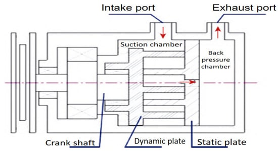
Figure 14.
Schematic diagram of scroll hydrogen circulating pump [71].
Zhang et al. [72] used the Taguchi method and analysis of variance (ANOVA) to quantify the effects of a range of factors on the shaft power of a scroll hydrogen pump and its volumetric efficiency. The results contributed to the design and operation control of the FCV vortex hydrogen pump. Lu [73] carried out a three-dimensional numerical simulation of the gas flow field in a vortex dry pump. The model was meshed by ICEMCFD (The Integrated Computer Engineering and Manufacturing Code for Computational Fluid Dynamics). An elastic smooth mesh method was applied to realize the mesh update, and the flow field and temperature field in the vortex pump were simulated by CFD (CFX(14.0) software), the computational fluid dynamics software, and the working process in the pump was analyzed, which provided a theoretical basis for further research on the dry vortex vacuum pump.
In a vortex hydrogen circulation pump, the bearing assembly tolerance affects the radial exposure force. Due to the gap between the sub-crankshaft and the bearing, the radial contact force of the assembly tolerance presents a high-frequency oscillation because the value of the radial swimming gap is very small. There is a local effect—a swimming gap collision contact force when considering the bearing assembly tolerance. Each collision time is short, and the pulse is small, with serious impacts on the radial force of the minor crankshaft and the angular acceleration. The presence of gaps causes high-frequency shaking of the contact force, and the contact force increases with the assembly gap. However, as the assembly gap of the component rises, the frequency of the oscillation peaks lessens. This is because the bearing and the secondary crankshaft contact each other for longer when the gap is large. The larger the gap, the lower the contact frequency, but the higher the contact force. As a result, it is extremely important that researchers identify the most suitable assembly tolerance for practical applications. If the assembly tolerance is large, the contact force will increase. Both will reduce the assembly quality and affect the stability and durability of the vortex hydrogen pump. This point should be taken into account during the design process of a vortex hydrogen pump.
4.3. An Overview of the Vortex Hydrogen Circulation Pump
A vortex hydrogen circulating pump is mainly composed of a connector, shaft cover, motor, pump cover, pump bottom, impeller, and a sealing ring. Figure 15a is a structural diagram of the hydrogen circulating pump, and Figure 15b is a disassembly diagram of the vortex hydrogen circulating pump.
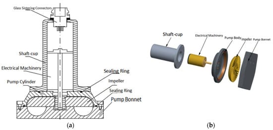
Figure 15.
(a) Schematic diagram of the structure of a vortex hydrogen circulation pump [74]; (b) Schematic diagram of explosion of a vortex hydrogen circulation pump [74].
A vortex hydrogen circulation pump is mainly composed of a motor, a partition, and an impeller. The whole design adopts the principle of no through shaft. Through magnetic levitation, the motor drives the other side of the partition of the impeller rotation. Because the motor and the impeller are connected without an axis, this can ensure that the motor on one side is completely separated from the flowing hydrogen on the other side, avoiding mixing of the oil and gas. On the one hand, the service life of the motor is enhanced, on the other hand, it cleverly addresses the explosion risk caused by oil and gas contact in the hydrogen circulation system.
The volume and weight of the vortex hydrogen circulating pump have great advantages over other hydrogen pumps. The volume is reduced by two-thirds and the weight is reduced by a half compared with the equivalent pump. The pump can better match the hydrogen power system, effectively reduce the volume and weight of the hydrogen fuel system, and reduce the consumption of hydrogen energy.
4.4. An Overview of the Lobe Hydrogen Circulation Pump
The vane type of hydrogen circulating pump has a compact structure, high efficiency, a low pressure ratio, and strong adaptability to low temperature. However, when the rotor rotates, the intake and exhaust volume may change periodically, creating uneven airflow and leading to pulsatile characteristics.
Dong et al. [75] adopted a dynamic grid as a means to calculate the rotor domain of the blade and studied the impacts of diverse speeds on the exhaust flow, transient pressure pulsation, external noise, and vibration. It was shown that when the pressure ratio is kept constant, the volume efficiency, vibration acceleration level (VAL), and the external noise are directly proportional to the lobe rotor speed. Zhou et al. [76] designed cam hydrogen circulating pumps with different gap schemes and studied the flow characteristics and volume efficiency under different pressure ratios based on a minimum radial force pulsation scheme. Furthermore, they analyzed the effects of different rotor–rotor and rotor–casing radial gaps on the pulsation characteristics and volume efficiency of the pump flow. Because of the characteristics of periodic suction and exhaust, air flow tends to produce pressure pulsation and flow pulsation. The high speed and high pressure ratio simultaneously further strengthen the airflow pulse, producing violent vibration and noise, seriously affecting the driving comfort of hydrogen energy vehicles, and accelerating the aging of hydrogen fuel cells.
4.5. An Overview of the Screw-Type Hydrogen Circulating Pump
The screw pump possesses effective self-priming performance and has a long service life, but also low volume and mechanical efficiency as well as heavy mass. The commonly used section profile is the cycloid–involute outline. A discontinuous spatial contact curve exists in the running process of the screw rotor, which leads to the problem of obvious gas leakage in the adjacent working area. Many studies have focused on the refinement and improvement of this traditional cross-section and its shaped screw rotor. Wang et al. [77] used the eccentric involute and its conjugation curve to smoothly connect the eccentric involute and the supplementary circular arc to construct a new eccentric involute screw rotor (EIR) with a continuous spatial contact curve. They analyzed the influence of the geometric parameters on the area utilization and spatial contact curves of the proposed EIR. Later, Wang et al. [78] proposed a two-segment variable pitch screw rotor generated from a constant cross-section profile along the spiral scan and developed a prototype of a two-screw vacuum pump. The results showed that the rotor had many advantages, including high limit vacuum, easy processing, and low noise vibration. Li et al. [79] developed a model of the dynamic characteristics of a dry screw vacuum pump. The model enables analysis of the load and power distribution of a dry screw vacuum pump. The torque of the synchronous gear can be reduced by choosing the appropriate drive shaft.
The working chamber volume of the fixed-pitch cylindrical rotor stays constant, generating higher exhaust power without internal compression. The working cavity volume of the variable-pitch cylindrical rotor gradually decreases from the suction end to the exhaust end, and the internal compression leads to a decrease in the exhaust power. Therefore, a variable-pitch vacuum pump is more energy efficient than a fixed-pitch vacuum pump. However, the pitch of the variable-pitch rotor exhaust part becomes smaller, so the rotor space is deep and narrow, making processing difficult, and the tooth width of the rotor at the exhaust end is reduced, making reflux easier. This reduces the ultimate vacuum degree and pumping efficiency of the vacuum pump. To avoid the above contradiction, Zhang et al. [80] proposed an optimized design of the conical rotor profile with a tunable flow field gap, establishing a mathematical model of the geometry and performance characteristics of the conical rotor pump. Experiments undertaken showed that the axial power of the tail rotor was less than the two cylindrical rotors compared with the fixed-pitch and variable-pitch cylindrical rotors.
4.6. An Overview of the Roots-Type Hydrogen Circulating Pump
The Roots type of pump involves the application of Roots rotor rotation for inhalation, compression, and discharge. The Roots type, because of the rotor movement mechanism, can cause a large pressure rise, enabling a wide range of applications. Figure 16 shows the fluid domains generated by the Roots rotor in SCORG, comprising three parts [81]: a rotor domain, an import region, and an exit region.

Figure 16.
Fluid domain model of Roots rotor [81].
However, the Roots pump also exhibits periodic volume changes during operation that cause the flow pulse and pressure pulsations to affect the work efficiency. Moreover, some in-pump high-pressure ratios that are required to work under special conditions further aggravate the airflow pulsation, resulting in severe flow shock vibration and aerodynamic noise. Some scholars have sought to optimize the flow state by improving the structure and reducing the turbulence in the internal flow field so as to reduce the gas pulsation, improving the operation stability to a certain extent, and reducing the generation of negative effects, such as vibration and aerodynamic noise caused by the flow. Zhou et al. [82] proposed a new Roots pump composed of six curves and a sharp point, which improved the area utilization, flow, and sealing, which was conducive to high-speed noise reduction. Many tests have shown that the pressure difference and shear drive can affect the generation of the gap leakage flow, which causes the rate of flow and pressure to show large amplitude high-frequency pulsation characteristics. With the help of computational fluid mechanics and experimental techniques, some scholars have deconstructed the internal flow field of the pump and explored the internal flow characteristics of the Roots pump. Li et al. [83] used computational fluid mechanics and experimental verification methods to study the Roots hydrogen circulating pump under different pressure ratio conditions, which showed that change in the pressure ratio makes a difference to the flow mode in the hydrogen circulation pump chamber, and the gap leakage flow scale increases with the pressure ratio. Kong et al. [84] put forward a new structure of a reflux groove to inhibit the pressure pulsation of the Roots pump and analyzed the mechanism of the reflux groove on the pressure pulsation, flow pulsation, and volume efficiency at different rotational speeds. The several circulating pumps described above have different structures and different characteristics. The appropriate circulating pump should be selected according to the different working conditions and the environmental requirements. At present, the internal temperature of a hydrogen circulating pump is relatively low during the low temperature start of the fuel cell system. It is likely that condensation occurs when the hot and wet exhaust gas from the chimney outlet flows through the hydrogen circulating pump. This makes the condensed water droplets produce more noise and vibration. At the same time, it can cause more damage and reduce the life of the fuel cell. This reduces the stability of the pump. With the rapid development of the vehicle fuel cell in the direction of high power and high efficiency, the hydrogen circulating pump needs to reach a higher speed and pressure ratio to meet the hydrogen return flow required by the system. This makes the condensed water droplets produce more noise and vibration, resulting in the circulating pump producing greater damage, reducing the life of the fuel cell. Therefore, one of the problems that needs to be solved at present is how to reduce the attachment of condensate water or how to reduce the generation of condensate water. Moreover, because the circulating hydrogen requires absolutely no oil, and the hydrogen can easily leak, design of the hydrogen pump is challenging and the manufacturing cost is high.
Furthermore, as the motor speed rises, the counter electromotive force of the motor increases until the counter electromotive force is greater than the maximum voltage supplied by the inverter to the motor, which will prevent the drive current from increasing. In addition, the speed continues to increase, and it is important to ensure weak magnetic control; that is, a certain current component is applied to the stator to produce the opposite magnetic flux to reduce the motor reverse electric motive force and to raise the motor speed. Under weak magnetic control, the weak magnetic current occupies the capacity of the inverter, which will lower the efficiency of the control system. In practical application scenarios, hydrogen circulation pumps used in fuel cells generally have a power of less than 2 kW, and the effect of weak magnetic control is limited, but it can achieve the effect of improving the speed and improving the anode cycle of fuel cells. If the power of the hydrogen circulation pump exceeds 2 kW or even higher, it will be necessary to ensure improvement in the motor speed to enable further development of the weak magnetic control.
5. An Introduction to the Ejector
5.1. An Overview of the Ejection Device Considering the Dynamics
Some scholars have previously used an ejector instead of a circulating pump to return the high temperature anode exhaust gas to the intake. Because it has many advantages, such as simple structure, reliable operation, and high durability, and no additional power energy utilization, it is gradually and widely now being used in PEMFC hydrogen recycling systems [85].
The structure and working principle of the ejector are shown in Figure 17. When the primary gas passes through the nozzle, in turn, the pressure is converted into kinetic energy by high pressure, forming a low-pressure area in the suction chamber. The low-pressure hydrogen is output from the radio reactor anode and returned to the reactor anode inlet after mixing.
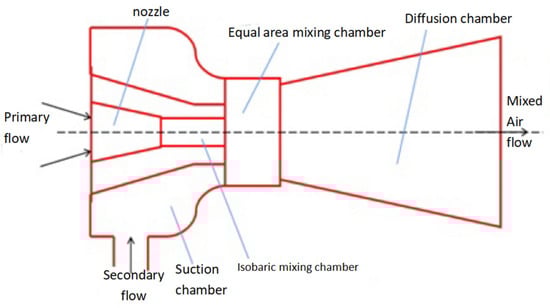
Figure 17.
Structure and working principle of an ejector.
Due to the varying pressure, temperature, relative humidity, and other operating conditions of a PEMFC, there may be a slight deviation between its performance and the optimal conditions. As a result, researchers have proposed different geometric shapes and ejector structures for PEMFC optimization. For instance, Nikiforow [86] developed a discrete primer that regulates the fuel flow by employing solenoid valves with static flow limiters of various sizes. However, when the fuel flow in the current limiter reaches subcritical levels, it leads to a decrease in the current increment, which subsequently affects the efficiency.
Based on the joint efforts of many researchers both here and abroad, the single nozzle ejector has gradually been improved, and some scholars have introduced it into refrigeration, seawater, and other technologies. Researchers have found that the single nozzle ejector could not meet the increasing working needs and challenging working conditions of a PEMFC. Therefore, scholars opened the research path for the multi-nozzle ejector. Xue et al. [87] proposed a multi-nozzle ejector, which switches the operating conditions of the nozzle and switches the hydrogen supply without significantly changing the main flow pressure. It can easily control the primary mass flow rate and maintain a relatively stable anode inlet pressure, as shown in Figure 18.

Figure 18.
Multi-nozzle ejector structure [87].
Kuo et al. [88] proposed a passive Venturi ejector system and demonstrated that it stabilizes the hydrogen supply faster than conventional mechanical systems, which means that not only is the hydrogen utilization rate and environmental safety of the PEMFC system improved, but the overall hydrogen consumption is reduced. Song et al. [89] proposed a dual-nozzle ejector, as shown in Figure 19a. Simulation results showed that the dual nozzle mode was more suitable for high power output at low hydrogen supply pressure than other modes. Du et al. [90] designed a coaxial dual-nozzle ejector for hydrogen recycling, whose structure is shown in Figure 19b. Chen et al. [91] also considered the optimized design and testing of a nested nozzle PEMFC hydrogen pilot device, whose structure is shown in Figure 20. They added a bypass airflow channel to the HSRS to complement the main cycle route and extended the lower limit of the operating power range of the PEMFC system from a minimum of 9 percent to 100 percent power output on a 150 kW stack. Liu et al. [92] established a three-dimensional dynamic model of a 130 kW PEMFC system and studied the dynamic characteristics of the system during startup and power change. The results showed that when the pressure difference between the primary flow and the secondary flow was less than 10 kPa, the secondary flow could not be sucked into the ejector, and that multiple ejectors can be used to expand the hydrogen supply range.
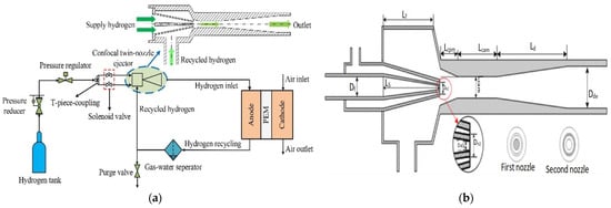
Figure 19.
(a) Schematic diagram of HSRS based on confocal dual-nozzle ejector [89]; (b) Coaxial double-nozzle ejector structure [90].
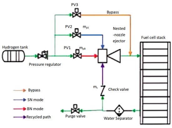
Figure 20.
The hydrogen supply and circulation system are constructed with nested nozzle ejectors and bypasses [91].
American Nuvera Fuel Cells [93] published a patent US10249888B2, which proposed a device that can be used for fuel cells to passively control the hydrogen circulation flow through the anode exhaust pressure. The Swiss company Belenos Clean Power Holding AG [94] published a patent EP2565970A1, which proposed a pulsed ejector. Jenn-Jiang Hwang et al. [95] proposed a working mode combining continuous flow and pulse flow to solve the problem of the low power cycle efficiency of an ejector. When the reactor runs at high power, the continuous flow mode is adopted to adjust the pressure and flow of the primary flow through the proportional valve. When the reactor is running at low power, the pulse flow mode is adopted, and the pulse flow is formed by periodically opening and closing the solenoid valve for circulation. Brunner et al. [96] developed a variable flow ejector by adding a needle at the primary flow inlet that can change the flow area of the main nozzle to adjust the flow. However, this way of adjusting the primary flow imposes significant demands on the movement of the needle—long-term use will lead to needle wear, poor durability, and other problems. Dirk Jenssen [97] designed a similar variable geometry ejector based on the variable flow ejector developed by Brunner and proposed a hydrogen cycle system combining the variable geometry ejector and cascade reactor to broaden the working range of the ejector by improving its ejector performance under low power conditions.
In some studies, the ejector is regarded as 2D [85], which lacks the detailed description of the flow field in the ejector and ignores the non-axisymmetrical flow characteristics in the ejector. The simulation results need to be further verified by experiments.
At present, no matter how the diameter of the ejector mixing zone changes, it is still difficult to meet the hydrogen cycle demand of the reactor below 80 kW. On the one hand, there are limitations of the stimulator itself; the primary flow rate is small under low power conditions, and the small flow rate produces a small shear force, resulting in a low secondary flow rate under low power. It is difficult for the exciter to adapt to the low power conditions of the reactor.
5.2. An Overview of the Numerical Simulation of an Ejector
Rogié et al. [98] established a one-dimensional thermodynamic model that was developed to characterize the performance of an ejector. The ejector assembly efficiency of the CFD simulation is extracted by a genetic algorithm, and the performance of the hydrogen fuel ejector is optimized by means of a simple transient simulation model of the vehicle storage tank. The new ejector fueling procedure is also compared in operation with the traditionally used expansion valve. The results show that in order to reduce the demand for high pressure hydrogen, optimized ejectors can be used, thus reducing the energy consumption and refueling time. Han et al. [99] focused on exploring the characteristics of phase transition and two-phase flow in hydrogen recycling ejectors and established a two-phase CFD model with phase transition based on the classical theory of nucleation and droplet growth. In the same year, Han et al. [100] also created a three-dimensional multi-component model to calculate the dynamics model of the fluid to study the synergistic transient properties of hydrogen recycling components (hydrogen ejector, and purge valve) in 80 kW PEMFC. The results showed that the entrainment performance of the ejector decreased under unsteady purging. Even during the purge shutdown, the pressure of the secondary flow fluctuated greatly. The velocity and pressure in the ejector changed markedly, especially in the mixing chamber.
Most studies have focused on ejectors with fixed geometry with their performance limited to relatively narrow operating conditions. Song et al. [101] evaluated the performance of confocal two-nozzle primers and optimized their geometric parameters by using a 3D computational fluid dynamics model. The results showed that the double nozzle mode varied the outlet pressure compared to the single nozzle mode. This study provides a relatively feasible method for the design of new ejectors and expanding the narrow working range of the ejectors for PEMFC hydrogen supply and recirculation systems. Huang et al. [102] analyzed, manufactured, and evaluated a vacuum generator for passive hydrogen recovery in a PEMFC system with a rated output power of 10 kW. The influence of the fluid inlet pressure and temperature on the parameters of the ejector device recirculation ratio and hydrogen stoichiometric ratio was studied by simulating and using 3D printing technology. The simulation results showed that the recycling ratio and the hydrogen stoichiometry were inversely proportional to the primary inflow pressure and the secondary inflow temperature. With increase in the primary inflow pressure, the hydrogen recovery performance will also decrease.
At present, there are two main technical difficulties associated with the ejector device. One is how to efficiently control the primary flow gas pressure effectively to meet the fuel consumption demand of the reactor. The other is that the casting device has difficulty meeting the casting requirements under different power conditions. Although these complex ejector designs effectively widen the working power scope of PEMFC systems, these studies usually do not consider the actual manufacturing problems in production and the harsh working environments in practical applications. The researchers may also only use simplified fuel reactor models to predict the response of the anode recirculation system (ARS) to any stack operating conditions, focusing only on the anode side, without considering other subsystems. Moreover, the type of material, the minimum manufacturing nozzle aperture, and the nozzle wall thickness also impose limits on the ejector geometry and hydrogen content. Most previous multi-nozzle ejectors were produced using plastic rather than more durable metal materials and the wall thickness was extremely thin. At high and constantly changing H2 pressures and rapid temperature changes (from −200 to 350 K around the nozzle area), these products may create a higher probability of failure. Furthermore, the production of multi-nozzle ejectors will demand diverse wall thicknesses, which might lead to inappropriate mixing chamber geometry and, thus, significantly affect the hydrogen entrainment ratio of the ejector. Manufacturing challenges, control difficulties, and potential system pressure interference make these design solutions unsuitable for practical applications.
In addition to the above problems, similar problems arise to the hydrogen circulating pump with regard to the reaction product of the water. Despite studying the optimization of ejector geometry parameters and ejector operating conditions, few studies have focused on the membrane water distribution and the resulting variation in PEMFC performance. At present, we also lack studies on water resource allocation within a PEMFC. The key to improving the efficiency of the PEMFC system is the water management and gas fuel utilization at the cathode and anode of the hydrogen fuel cell. Some scholars suggest that the recycling based on the PEMFC anode can provide humidification and promote the recycling of hydrogen; adding the cathode will recirculate oxygen through the pressure difference and blow out the liquid water produced by the cathode. From this point of view, the water pipe is crucial to improving the overall performance of fuel cells and reducing the water flooding in the anode and cathode.
6. An Overview of the Water Separator
The water separator is a crucial auxiliary component of the hydrogen recirculation subsystem of the PEMFC system. The unreacted excess hydrogen is separated from the liquid water in it and then returns to the circulation loop to ensure the purity of the hydrogen for secondary use. The cyclone water separator uses the droplet in the process of rotating motion to separate the droplet from the main steam flow due to the action of the inertial force and the centrifugal force. The detailed working principle is shown in Figure 21. The cyclone separator is to introduce the mixture of water and water into the separator from the intake pipe tangentially. Due to the large flow energy of the steam introduced, rotation motion with great speed in the tangential direction is formed, so that the droplet has a large inertia force and centrifugal force. Under the action of the inertial force and the centrifugal force, the droplets collide with the inner surface of the cyclone shell and separate from the steam flow. The separated droplets flow out of the separator along the inner surface of the shell under the action of gravity.

Figure 21.
Structure diagram of cyclone separator.
With the development of CFD technology, many researchers use this method to study the internal flow characteristics of cyclone separators to provide theoretical support for improving their efficiency. Han et al. [103] developed a two-phase Euler–Lagrangian simulation model to study the gas flow characteristics and droplet trajectory and the membrane distribution in the separator. In addition, a bench was made to test the comprehensive performance of the separator. The results showed that the CFD model could precisely forecast the performance of the gas–water separator. By comparison between the mixed hydrogen and air, it was found that the density of the gas-phase fluid had a huge impact on the pressure drop.
Feng et al. [104] disclosed a patent CN111785993A. The patent was for a single structure water and gas separator to adapt to the requirements of water and gas separation at different power levels, through a parallel low power water separator and a high-power water separator at the reactor anode outlet, to ensure the single ejector radiation operation over a wide power change range.
Liu et al. [105] designed a special two-stage cyclone steam separator and carried out a detailed numerical simulation of its separation performance. According to the structure of the two-stage cyclone, a calculation and analysis model was established, and the effects of different inlet velocity and humidity on the separation characteristics of the separator were studied. An air–water cooling test loop was established to verify the model.
Based on the vane-type gas-water separator, Dong et al. [106] comprehensively studied the gas–liquid two-phase flow field and performance indicators in the separator by using a Euler–Euler model combined with a multi-fluid VOF (fluid volume) modeling method and conducted sensitivity analysis on the structural parameters. The incidence angle of the blade structure was found to need to be between 45° and 50°, and a contraction ratio of 1:3 was found to achieve a higher separation efficiency and a lower pressure drop.
The cyclone water separator has the advantages of simple structure, easy manufacture, no moving parts, and of being strong and durable. The structure of the cyclone water separator is simple, but the flow of the internal gas is more complex, and the droplet is not only affected by centrifugal force, but also by other factors, such as the collisions between droplets, condensation, and wall impact. Simulation studies showed that droplets of different sizes have different movement tracks in the separator. Small droplets are more significantly affected by air pulsation and the carrying of large droplets, which has a greater impact on the separation performance. Therefore, the larger the droplet particle size, the higher the separation efficiency.
A tangential air inlet is a commonly used structure, which has a low cost, involves easy processing, and has a good separation effect. However, this structure leads to an unbalanced pressure distribution inside the separator and a large pressure loss. To date, different scholars have proposed different air inlet structural designs, including tangential, volute, spiral, axial blade, radial inlet, and spiral inlet. The advantages and disadvantages are summarized in Table 3.
Table 3.
Comparison of advantages and disadvantages of entrance structure [107].
Although the cyclone separator has a simple structure, the flow characteristics are complex, and subtle design structure changes may have a greater impact on the separation effect. In the process of separation, the liquid droplets will form a liquid film inside the separator, and the liquid film is easy to break under the action of tangential force, thus forming secondary droplets. At present, there is little research on the motion characteristics and fracture mechanisms of the liquid film in the separator, which is expected to become the key development direction in the future. In addition, the drainage effect and flow resistance of the separator are still to be solved.
7. Summary and Outlook
As mentioned above, the direct discharge circulation mode has the simplest structure, but a large amount of unreacted hydrogen is directly discharged, which is not only wasted but also creates safety problems. In the dead-end mode, the gas utilization rate of hydrogen is improved, but after long-term operation, the anode gas channel will be blocked, and the battery voltage will be attenuated significantly. The recirculation mode delivers hydrogen to the anode inlet of the reactor through the circulation device to participate in the chemical reaction, which improves the utilization rate of hydrogen. Discharging the liquid water from the anode can prevent the battery voltage attenuation problem caused by flooding, but the introduction of circulation components will lead to a complex system and increase the cost. Therefore, in order to further improve the efficiency of fuel cells, it is essential to develop a high-performance and low-cost hydrogen cycle system. In actual operation, in order to improve battery performance, excess hydrogen is usually supplied to the anode. The actual flow rate of hydrogen is about 1.1 to 1.5 times the theoretical flow rate. A total of four hydrogen cycle schemes are summarized. Each has its own advantages and disadvantages, as shown in Table 4.
Table 4.
Technical comparison of hydrogen supply mode.
In recent years, the level of science and technology in various countries has been rapidly improved, and the hydrogen circulation system has been gradually updated. Of course, neither of these cycle options can be achieved without an ejector or hydrogen cycle pump. At present, the technology of ejectors and hydrogen circulation pumps is becoming better and better, but under certain conditions, it cannot meet the higher requirements that people expect.
Specifically, recent studies have shown that the dual injector system, paired with two hydrogen proportional valves, can be optimized and controlled to fully cover the operation of A PEMFC reactor from 40 A (or 6 kW) to 600 A (or 70 kW). In addition, an auxiliary ejector (BE) design model has been presented, and the ejector geometrical parameters and performance (u) have been subject to sensitivity analysis. The results show that the BE can provide satisfactory u above 0.8 under higher power output, and a u higher than 0.6 for lower power output with a position (Lb), angle (A), and width (W) of 1.1, 30°, and 4 mm when the PEMFC works from 17.9 to 84 kW. Due to the poor casting effect under low power conditions, there are problems in the selection of the injection nozzle materials and shapes. Some scholars have carried out structural optimization design of the ejector to broaden its effective spraying range. At present, scholars mainly discuss the general effects of hydrogen ejectors with regard to the performance and water distribution of conventional flow field PEMFCs. Some scholars have studied the performance and water distribution of PEMFCs with hydrogen ejectors under different operating parameters. According to the simulation results, keeping the anode relative humidity at 60% and the cathode relative humidity at 20% can achieve higher performance and reduce the degree of water flooding in PEMFCs with hydrogen ejectors. In addition, there should be a focus not only on the steady-state performance of PEMFCs equipped with hydrogen ejectors under various working conditions, but also investigation of the transient performance of PEMFCs when using hydrogen ejectors.
Recent studies have found that during compression, a new high-seal rotor has better sealing between the rotors and a significant pressurization effect compared to conventional claw hydrogen circulation pumps. Gas leakage between rotors is reduced as the gas flows through long and narrow zigzag meshing gaps. In the process of compressing the exhaust, the gas leakage rate between the rotors of the new gear jaw is reduced by 31.42% and 33.09% compared with that between traditional rotors. The volumetric efficiency of the traditional claw type hydrogen circulation pump is 67.30%, and that of the new gear claw type hydrogen circulation pump is 78.22%, with the volumetric efficiency increased by 10.92%. Dongdeshiye reported on a small batch application of a hydrogen circulating pump produced in China, which achieved a cold start temperature of −40 °C. With the advancement of technology, the industry’s technical requirements for hydrogen circulating pumps are also constantly increasing. The current development of hydrogen circulating pumps mainly indicates the following trends: (1) The low-temperature icebreaking capacity of hydrogen circulating pumps. Since the remaining hydrogen after the fuel cell reactor reaction contains a large amount of water vapor or even liquid water, it will freeze in a low temperature environment, affecting the normal use of the hydrogen cycle pump, thus affecting the low temperature start-up performance of the fuel cell engine, so the ice breaking capacity of the hydrogen cycle pump has become an essential requirement of the industry. At present, there are two technical routes in the industry: heating ice breaking and torque ice breaking, and there are a number of installed applications. (2) Development of other forms of hydrogen cycle schemes. Some enterprises choose to use a single ejector or a parallel ejector with a hydrogen circulating pump when designing the hydrogen circulating system.
The difference in power consumption between a series parallel mode and a hydrogen circulating pump has been considered. The adiabatic efficiency of a hydrogen circulating pump is calculated according to a value of 0.45. The results indicate that the maximum power consumption of a hydrogen circulation pump is 1020 W, while the maximum power consumption in parallel mode is 190 W, which has been reduced by 81.4% compared with the same period last year. The maximum power consumption in series mode is 150 W, which is 85.3 percent lower than for the previous year. Obviously, the use of a combined ejector can greatly reduce the power consumption of a hydrogen circulating pump. The reduction in the power of a hydrogen circulating pump can not only improve the efficiency of the entire system, but more importantly, it is conducive to the design and selection of the hydrogen pump, because the technical difficulties associated with low-power and low-flow hydrogen circulating pumps are relatively low, the cost is low, and the reliability is higher. ith regard to the current situation, it is difficult to use only the ejector to adapt to the wide power range of high-power fuel cell vehicles. The power range that can meet the demand for the hydrogen cycle through optimization design is 80–200 kW; when it is lower than 80 kW, the performance of the ejector decreases rapidly and cannot meet the demand for the hydrogen cycle.
Compared with various hydrogen cycle systems proposed in recent years, the fuel cell system output power of the ejector scheme is 0.1~0.3 kW greater than that of the hydrogen cycle pump scheme, and the system efficiency is 0.2–0.7% lower than that of the hydrogen cycle pump scheme. The hydrogen consumption of the ejector scheme is 1~3% greater than that of the hydrogen circulating pump, and the hydrogen utilization rate is 1.6–3.9% lower than that of the hydrogen circulating pump. The dynamic response of the ejector is comparable to that of the hydrogen circulating pump. The pressure difference between the inlet and outlet of hydrogen in the ejector scheme is 1.2–2.6 kPa lower than that in the hydrogen circulating pump scheme.
The hydrogen fuel cell circulation system has basically now formed a relatively perfect framework, which can ensure safety in hydrogenation, hydrogen storage, hydrogen discharge, hydrogen leakage, and emergency situations. The progress in simulation, the accumulation and optimization of safety tests, the wide application of a variety of fault analysis methods, and the continuous improvements in sensor technology, are all likely to promote the process of commercialization, scaling, and industrialization of fuel cell vehicles.
Author Contributions
Conceptualization, J.L. (Jiqiang Li), J.L. (Jichao Li) and K.Z.; methodology, formal analysis, K.Z.; software, J.L. (Jichao Li); writing—original draft preparation, T.W. and C.C.; validation, investigation, resources, T.W. and C.C.; data curation, J.L. (Jiqiang Li), T.W. and C.C.; writing—review and editing, J.L. (Jichao Li) and K.Z.; visualization, J.L. (Jichao Li) and K.Z.; supervision, project administration, J.L. (Jichao Li) and K.Z.; funding acquisition, J.L. (Jichao Li) and K.Z. All authors have read and agreed to the published version of the manuscript.
Funding
This research was funded by the “Hundred Outstanding Talents” Support Program of Jining University, a provincial-level key project in the field of natural sciences, grant number 2023ZYRC23 and Ludong University (20220035).
Data Availability Statement
All data are contained within the article.
Conflicts of Interest
The authors declare no conflicts of interest.
References
- Chen, X.; Chen, Y.; Liu, Q.; Xu, J.; Liu, Q.; Li, W.; Zhang, Y.; Wan, Z.; Wang, X. Performance Study on a Stepped Flow Field Design for Bipolar Plate in PEMFC. Energy Rep. 2021, 7, 336–347. [Google Scholar] [CrossRef]
- Jiao, K.; Xuan, J.; Du, Q.; Bao, Z.; Xie, B.; Wang, B.; Zhao, Y.; Fan, L.; Wang, H.; Hou, Z.; et al. Designing the Next Generation of Proton-Exchange Membrane Fuel Cells. Nature 2021, 595, 361–369. [Google Scholar] [CrossRef] [PubMed]
- Li, M.; Yang, Q.; Zhang, C.; Huang, S.; Zhang, M.; Zhang, G.; Zhao, L.; Jiang, S. Experimental and numerical study of the temperature evolution in hydrogen cylinder under fast-refueling process. Int. J. Heat Mass Transf. 2023, 211, 124220. [Google Scholar] [CrossRef]
- Tian, Y.; Han, J.; Bu, Y.; Qin, C. Simulation and analysis of fire and pressure reducing valve damage in on-board liquid hydrogen system of heavy-duty fuel cell trucks. Energy 2023, 276, 127572. [Google Scholar] [CrossRef]
- IMO Hot Topic—Reducing Greenhouse Gas Emissions from Ships. 2018. Available online: https://cimrc.shmtu.edu.cn/2022/1214/c5091a195998/page.htm (accessed on 12 December 2023).
- Bouman, E.A.; Lindstad, E.; Rialland, A.I.; Strømman, A.H. State-of-the-art technologies, measures, and potential for reducing GHG emissions from shipping—A review. Transp. Res. Part D Transp. Environ. 2017, 52, 408–421. [Google Scholar] [CrossRef]
- Jung, W.; Choi, M.; Jeong, J.; Lee, J.; Chang, D. Design and analysis of liquid hydrogen-fueled hybrid ship propulsion system with dynamic simulation. Int. J. Hydrogen Energy 2024, 50, 951–967. [Google Scholar] [CrossRef]
- Elkafas, A.G.; Rivarolo, M.; Gadducci, E.; Magistri, L.; Massardo, A.F. Fuel Cell Systems for Maritime: A Review of Research Development, Commercial Products, Applications, and Perspectives. Process 2023, 11, 97. [Google Scholar] [CrossRef]
- Hou, J.B.; Yang, M.; Zhang, J.L. Active and passive fuel recirculation for solid oxide and proton exchange membrane fuel cells. Renew. Energy 2020, 155, 1355–1371. [Google Scholar] [CrossRef]
- Muthukumar, M.; Rengarajan, N.; Velliyangiri, B.; Omprakas, M.A.; Rohit, C.B.; Raja, U.K. The development of fuel cell electric vehicles—A review. Mater. Today Proc. 2021, 45, 1181–1187. [Google Scholar] [CrossRef]
- Hydrogen Council. Path to Hydrogen Competitivenes: A Cost Perspective; Hydrogen Council: Brussels, Belgium, 2020. [Google Scholar]
- Meng, X.Y.; Gu, A.L.; Wu, X.G.; Zhou, J.; Liu, B.; Mao, Z.Q. High-quality development prospect of hydrogen energy industry in China. Sci. Technol. Her. 2020, 38, 77–93. [Google Scholar]
- Le, T.T.; Sharma, P.; Bora, B.J.; Tran, V.D.; Truong, T.H.; Le, H.C.; Nguyen, P.Q.P. Fueling the future: A comprehensive review of hydrogen energy systems and their challenges. Int. J. Hydrogen Energy 2023, 54, 791–816. [Google Scholar] [CrossRef]
- Zhang, C.; Cao, X.; Bujlo, P.; Chen, B.; Zhang, X.; Sheng, X.; Liang, C. Review on the safety analysis and protection strategies of fast filling hydrogen storage system for fuel cell vehicle application. J. Energy Storage 2022, 45, 103451. [Google Scholar] [CrossRef]
- Kendall, K. Hydrogen and Fuel Cells. Ref. Modul. Earth Syst. Environ. Sci. 2022, 305–316. [Google Scholar] [CrossRef]
- Zhang, J.; Feng, J.; Wang, Z.; Wu, Y.; Lu, S.; Kong, X.; Huang, T.; Wang, Z.; Wang, X.; Wan, Z. Study on the effect of static magnetic field strength and arrangement on the working performance of PEMFC with different flow fields. Energy Convers. Manag. X 2024, 21, 100517. [Google Scholar] [CrossRef]
- Zhu, K.-Q.; Ding, Q.; Zhang, B.-X.; Xu, J.-H.; Li, D.-D.; Yang, Y.-R.; Lee, D.-J.; Wan, Z.-M.; Wang, X.-D. Performance enhancement of air-cooled PEMFC stack by employing tapered oblique fin channels: Experimental study of a full stack and numerical analysis of a typical single cell. Appl. Energy 2024, 358, 122595. [Google Scholar] [CrossRef]
- Zhang, Z.; Tan, Y.; Yang, D.; Chu, T.; Li, B. A Finite Element Analysis Model-Based Study on the Effect of the Frame on Membrane Stresses in Proton Exchange Membrane Fuel Cells. Energies 2023, 16, 7044. [Google Scholar] [CrossRef]
- Ahmadi, N.; Rezazadeh, S. An Innovative Approach to Predict the Diffusion Rate of Reactant’s Effects on the Performance of the Polymer Electrolyte Membrane Fuel Cell. Mathematics 2023, 11, 4094. [Google Scholar] [CrossRef]
- Yoon, Y.-G.; Lee, W.-Y.; Park, G.-G.; Yang, T.-H.; Kim, C.-S. Effects of channel configurations of flow field plates on the performance of a PEMFC. Electrochim. Acta 2004, 50, 709–712. [Google Scholar] [CrossRef]
- Ferng, Y.-M.; Su, A.; Lu, S.-M. Experiment and simulation investigations for effects of flow channel patterns on the PEMFC performance. Int. J. Energy Res. 2008, 32, 12–23. [Google Scholar] [CrossRef]
- Ma, S.; Lin, M.; Lin, T.-E.; Lan, T.; Liao, X.; Maréchal, F.; Van Herle, J.; Yang, Y.; Dong, C.; Wang, L. Fuel cell-battery hybrid systems for mobility and off-grid applications: A review. Renew. Sustain. Energy Rev. 2021, 135, 110119. [Google Scholar] [CrossRef]
- de-Troya, J.J.; Álvarez, C.; Fernández-Garrido, C.; Carral, L. Analysing the possibilities of using fuel cells in ships. Int. J. Hydrogen Energy 2016, 41, 2853–2866. [Google Scholar] [CrossRef]
- Xing, H.; Stuart, C.; Spence, S.; Chen, H. Fuel Cell Power Systems for Maritime Applications: Progress and Perspectives. Sustainability 2021, 13, 1213. [Google Scholar] [CrossRef]
- Bai, Q.; Liu, Z.; Hsieh, C. Research on the Performance of Self-Made Open-Cathode Fuel Cell Stacks under Different Operating Conditions. Membranes 2023, 13, 881. [Google Scholar] [CrossRef] [PubMed]
- Shimpalee, S.; Lilavivat, V.; Van Zee, J.W.; McCrabb, H.; Lozano-Morales, A. Understanding the effect of channel tolerances on performance of PEMFCs. Int. J. Hydrogen Energy 2011, 36, 12512–12523. [Google Scholar] [CrossRef]
- Mahjoubi, C.; Olivier, J.-C.; Skander-Mustapha, S.; Machmoum, M.; Slama-Belkhodja, I. An improved thermal control of open cathode proton exchange membrane fuel cell. Int. J. Hydrogen Energy 2019, 44, 11332–11345. [Google Scholar] [CrossRef]
- Zhao, J.; Jian, Q.; Luo, L.; Huang, B.; Cao, S.; Huang, Z. Dynamic behavior study on voltage and temperature of proton exchange membrane fuel cells. Appl. Therm. Eng. 2018, 145, 343–351. [Google Scholar] [CrossRef]
- Fu, X.; Wen, Q.; Han, J.; Wei, J.; Li, Y.; Ning, F.; Zhou, X. One-step to prepare high-performance gas diffusion layer (GDL) with three different functional layers for proton exchange membrane fuel cells (PEMFCs). Int. J. Hydrogen Energy 2022, 47, 25769–25779. [Google Scholar] [CrossRef]
- Zhang, Z.; Quan, C.; Wu, S.; Zhang, T.; Zhang, J. An Electrochemical Performance Model Considering of Non-Uniform Gas Distribution Based on Porous Media Method in PEMFC Stack. Sustainability 2024, 16, 587. [Google Scholar] [CrossRef]
- Jarry, T.; Jaafar, A.; Turpin, C.; Lacressonniere, F.; Bru, E.; Rallieres, O.; Scohy, M. Impact of high frequency current ripples on the degradation of high-temperature PEM fuel cells (HT-PEMFC). Int. J. Hydrogen Energy 2023, 48, 20734–20742. [Google Scholar] [CrossRef]
- Yu, Y.; Guo, Y.; Ma, T. Prioritizing the hydrogen pathways for fuel cell vehicles: Analysis of the life-cycle environmental impact, economic cost, and environmental efficiency. Energy 2023, 281, 128322. [Google Scholar] [CrossRef]
- Zhang, L.X.; Li, J.; Li, R.Y.; Zhang, X.; Zhang, T. Research on the Hydrogen Supply System of Fuel Cell for Vehicle. J. Eng. Thermophys. 2022, 43, 1445–1458. [Google Scholar]
- Xu, X.J.; Yang, R.; Ji, Y.B. Review on key technologies of hydrogen fuel cell powered vessels. J. Traffic Transp. Eng. 2022, 22, 47–67. [Google Scholar]
- IEC 62282-2: 2012; Fuel Cell Technologies—Part 2-100: Fuel Cell Modules—Safety. International Electrotechnical Commission: Geneva, Switzerland, 2012.
- GB/T 33979-2017; Test Method for Low Temperature Characteristics of Proton Exchange Membrane Fuel Cell Power Generation System. National Standardization Administration Committee: Beijing, China, 2017.
- GB/T 34872-2017; Technical Requirements for Hydrogen Supply Systems for Proton Exchange Membrane Fuel Cells. National Standardization Administration Committee: Beijing, China, 2017.
- Huang, X.; Ding, T.W.; Zhao, H.H.; Du, J.; Zhao, Z.L. Review of Hydrogen safety control for vehicle Fuel Cell Systems. Automot. Dig. 2019, 4, 6–10. [Google Scholar]
- Ma, Q.Y.; Zhao, Z.L.; Zhao, H.H.; Wang, Y.P.; Du, J.; Bao, J.C. Overview of Fuel cell industry standards. Automot. Dig. 2020, 14–17. [Google Scholar] [CrossRef]
- American Bureau of Shipping. Guide for Fuel Cell Power for Marine and Offshore Applications; American Bureau of Shipping: New York, NY, USA, 2019. [Google Scholar]
- ISO 23273:2013; Fuel Cell Road Vehicles. ISO: Geneva, Switzerland, 2013.
- SAE J2578; Recommended Practice for General Fuel Cell Vehicle Safety. SAE: Warrendale, PA, USA, 2014.
- Hong, L. Fuel Delivery Control for Vehicular Fuel Cell Power Systems; Zhejiang University: Hangzhou, China, 2017. [Google Scholar]
- Ma, W.H.; Hao, D.; Guo, S.S.; Liu, Z.W. Analysis on anode hydrogen supply system of fuel cell engine. Automob. Parts 2021, 5, 95–98. [Google Scholar]
- Liu, J.F.; Li, Q.; Qin, Y.; Li, J.J. Developing status of hydrogen recycling system of proton exchange membrane fuel cell. Energy Technol. Manag. 2022, 47, 45–48. [Google Scholar]
- Gao, Y.; Lin, M.Z. Research on the performance characteristics of hydrogen circulation pumps for PEMFC vehicles. Int. J. Hydrogen Energy 2024, 50, 1255–1272. [Google Scholar] [CrossRef]
- Feng, J.; Xing, L.; Wang, B.; Wei, H.; Xing, Z. Effects of working fluids on the performance of a roots pump for hydrogen recirculation in a PEM fuel cell system. Appl. Sci. 2020, 10, 8069. [Google Scholar] [CrossRef]
- Hwang, J.J.; Wang, D.Y.; Shih, N.C. Development of a lightweight fuel cell vehicle. J. Power Sources 2005, 141, 108–115. [Google Scholar] [CrossRef]
- Han, Y.M. Analysis of Structural Characteristics of Toyota FCHV-4 Fuel Cell Vehicle. Shanghai Auto 2011, 1, 104–105. [Google Scholar]
- Wang, M.R.; Zhang, Y.; Zhang, X.F.; Yang, G.C.; Gong, R. Fuel Cell Hydrogen Circulation System and Control Method Thereof. China Patent CN202010457857.1, 10 September 2021. [Google Scholar]
- Ding, H.; Dong, Y.; Zhang, Y.; Yang, Y.; Wen, C. Energy efficiency assessment of hydrogen recirculation ejectors for proton exchange membrane fuel cell (PEMFC) system. Appl. Energy 2023, 346, 121357. [Google Scholar] [CrossRef]
- Matsunaga, M.; Fukushima, T.; Ojima, K. Powertrain system of Honda FCX Clarity fuel cell vehicle. World Electr. Veh. J. 2009, 3, 820–829. [Google Scholar] [CrossRef]
- Wang, W.; Qu, F.F.; Liang, R.L. Analysis of NEXO Technology of Hyundai Fuel Cell Vehicle. Automob. Parts 2020, 90–93. [Google Scholar]
- Li, C.Q.; Hao, Y.G.; Hu, S. A Fuel Cell Anode Hydrogen Circulation System and Its Control Method. China Patent CN202011502442.8, 26 March 2021. [Google Scholar]
- James, B.D.; Spisak, A.B.; Colella, W.G. Design for manufacturing and assembly cost estimate methodology for transportation fuel cell systems. J. Manuf. Sci. Eng. 2014, 136, 024503. [Google Scholar] [CrossRef]
- Yang, Z.Y.; Chen, L. Proton Exchange Membrane Hydrogen Fuel Cell Hydrogen Supply System and Control Method. China Patent CN202110422285.8, 16 July 2021. [Google Scholar]
- Ahluwalia, R.K.; Wang, X. Fuel cell systems for transportation: Status and trends. J. Power Sources 2008, 177, 167–176. [Google Scholar] [CrossRef]
- Yumiya, H.; Kizaki, M.; Asai, H. Toyota fuel cell system (TFCS). World Electr. Veh. J. 2015, 7, 85–92. [Google Scholar] [CrossRef]
- Kizaki, M.; Asai, H.; Yumiya, H. Advancing into the future with the Mirai fuel cell system. Toyota Tech. Rev. 2015, 61, 11. [Google Scholar]
- Li, Y.; Deng, J.; Wei, Q.S.; Liang, W.D.; Wang, H.X.; Yi, Y.; Zhao, Y.F.; Liu, J.; Liu, X.Q.; Liu, H. A Fuel Cell Hydrogen Supply System and Its Applied Fuel Cell System. China Patent CN201921132697.2, 31 March 2020. [Google Scholar]
- Xing, Z.Y.; Wang, S.K.; Xing, X.M. Fuel Cell Hydrogen Supply System Integrated in Parallel with Hydrogen Circulation Pump and Ejector. China Patent CN202110276499.9, 31 August 2021. [Google Scholar]
- Zhao, B.; Wei, H.; Zhang, Z.; Feng, J.; Peng, X. Effects of clearances size and fluid medium components on the thermodynamic performance of a claw pump for fuel cell vehicle. Int. J. Energy Res. 2022, 46, 15054–15065. [Google Scholar] [CrossRef]
- Dong, K.R.; Liu, G.B.; Gao, Z.C. Review of fuel cell hydrogen circulation system. Power Technol. 2021, 45, 545–551. [Google Scholar]
- Pan, S.Y.; Ren, C.J.; Wang, J.; Hao, X.; Xin, Y.J.; Wang, Z.L.; Cui, D. Transient flow characteristics of a claw hydrogen circulating pump with high sealing rotors. J. Harbin Inst. Technol. 2023, 55, 76–85. [Google Scholar]
- Wang, J.; Feng, H.; Zhao, F.; Cui, D.; Xi, Z.; Wang, Z. Geometric design of novel straight claw rotors for claw vacuum pumps. Mech. Mach. Theory 2019, 136, 244–255. [Google Scholar] [CrossRef]
- Gu, P.; Xing, L.; Wang, Y.; Feng, J.; Peng, X. A multi-objective parametric study of the claw hydrogen pump for fuel cell vehicles using Taguchi method and ANN. Int. J. Hydrogen Energy 2021, 46, 6680–6692. [Google Scholar] [CrossRef]
- Dong, K.; Liu, G.; Yang, Q.; Zhao, Y.; Li, L. Effect of thermal deformation on leakage clearance of claw hydrogen circulating pump for fuel cell system. Int. J. Hydrogen Energy 2022, 47, 28655–28669. [Google Scholar] [CrossRef]
- Dong, K.; Liu, G.; Yang, Q.; Zhao, Y.; Li, L.; Gao, Z. Flow field analysis and performance study of claw hydrogen circulating pump in fuel cell system. Int. J. Hydrogen Energy 2021, 46, 34438–34448. [Google Scholar] [CrossRef]
- Pan, S.; Wang, J.; Zhao, X.; Ren, C.; Xin, Y.; Wang, Z. New design and transient flow analysis of a claw vacuum pump with novel gear-claw rotors. Vacuum 2023, 216, 112470. [Google Scholar] [CrossRef]
- Feng, J.M.; Zhang, Q.Q.; Hou, T.F.; Peng, X.Y. Dynamics characteristics analysis of the oil-free scroll hydrogen recirculating pump based on multibody dynamics simulation. Int. J. Hydrogen Energy 2021, 46, 5699–5713. [Google Scholar]
- Wang, Y.F.; Wu, Y.G.; Liu, X.M.; Shu, Y.; Zhao, S.D.; Guo, Y. Research Status of Scroll Forming Process for Hydrogen Circulating Pump. J. Netshape Form. Eng. 2022, 14, 19–27. [Google Scholar]
- Zhang, Q.; Feng, J.; Zhang, Q.; Peng, X. Performance prediction and evaluation of the scroll-type hydrogen pump for FCVs based on CFD–Taguchi method. Int. J. Hydrogen Energy 2019, 44, 15333–15343. [Google Scholar] [CrossRef]
- Lu, Y.J. Numerical Simulation of Gas Flow in Vortex Dry Pump. Master’s Thesis, Northeastern University, Shenyang, China, 2015. [Google Scholar]
- Wang, X.K.; Shen, Y.W.; Zhao, H.B.; Cao, L.; Chen, S.; Jia, C.; Xie, X.F. Design and performance analysis of a compact hydrogen circulation pump. Chem. Ind. Eng. Prog. 2020, 39 (Suppl. S2), 89–96. [Google Scholar]
- Dong, L.; Zhou, R.; Liu, H.; Zhang, L.; Dai, C.; Mao, Y.; Hu, J. Effect of rotational speed on unstable characteristics of lobe hydrogen circulating pump in fuel cell system. Int. J. Hydrogen Energy 2022, 47, 21435–21449. [Google Scholar] [CrossRef]
- Zhou, R.; Dong, L.; Liu, H.; Dai, C.; Zhang, L. Excitation characteristics of lobe hydrogen circulating pump in polymer electrolyte membrane fuel cell under different clearances and pressure ratios. Appl. Therm. Eng. 2023, 226, 120230. [Google Scholar] [CrossRef]
- Wang, J.; Wu, M.; Cui, F.; Tan, Q.; Wang, Z. Research of a novel eccentric involute rotor and its performance analysis for twin-screw vacuum pumps. Vacuum 2020, 176, 109309. [Google Scholar] [CrossRef]
- Wang, J.; Zhao, L.; Zhao, X.; Pan, S.; Wang, Z.; Cui, D.; Geng, M. Optimal design and development of two-segment variable-pitch screw rotors for twin-screw vacuum pumps. Vacuum 2022, 203, 111254. [Google Scholar] [CrossRef]
- Li, D.; He, Z.; Sun, S.; Xing, Z. Dynamic characteristics modelling and analysis for dry screw vacuum pumps. Vacuum 2022, 198, 110868. [Google Scholar] [CrossRef]
- Zhang, L.; Liu, Y.; Zhang, Y.; Liu, W.; Chen, Z. Geometric design and performance analysis of conical-rotor screw vacuum pump with adjustable flow field clearances. Vacuum 2023, 214, 112201. [Google Scholar] [CrossRef]
- Jiao, H.Y.; Han, J.C.; Yang, D.S.; Liu, J.F.; Miao, L.L.; Zhou, X.L. Analysis of Profile Optimization of Roots Hydrogen Circulating Pump. Manned Spacefl. 2022, 28, 358–364. [Google Scholar]
- Zhou, S.; Jia, X.; Yan, H.; Peng, X. A novel profile with high efficiency for hydrogen-circulating Roots pumps used in FCVs. Int. J. Hydrogen Energy 2021, 46, 22122–22133. [Google Scholar] [CrossRef]
- Li, S.; Li, W.; Ji, L.; Zhai, H.; Li, Y.; Wang, C.; Li, X. Effect of pressure ratio on transient flow in hydrogen circulating pump. Int. J. Hydrogen Energy 2023, 48, 26937–26950. [Google Scholar] [CrossRef]
- Kong, X.; Han, J.; Guo, Y.; Feng, J.; Peng, X. Investigation on the pressure fluctuation of hydrogen Roots pump with a novel reflow structure for fuel cell vehicles. Int. J. Hydrogen Energy 2023, 50, 66–78. [Google Scholar] [CrossRef]
- Wang, X.; Xu, S.; Xing, C. Numerical and experimental investigation on an ejector designed for an 80 kW polymer electrolyte membrane fuel cell stack. J. Power Sources 2019, 415, 25–32. [Google Scholar] [CrossRef]
- Nikiforow, K.; Koski, P.; Ihonen, J. Discrete ejector control solution design, characterization, and verification in a 5 kW PEMFC system. Int. J. Hydrogen Energy 2017, 42, 16760–16772. [Google Scholar] [CrossRef]
- Xue, H.; Wang, L.; Zhang, H.; Jia, L.; Ren, J. Design and investigation of multi-nozzle ejector for PEMFC hydrogen recirculation. Int. J. Hydrogen Energy 2022, 45, 14500–14516. [Google Scholar] [CrossRef]
- Kuo, J.K.; Jiang, W.Z.; Li, C.H.; Hsu, T.H. Numerical investigation into hydrogen supply stability and IV performance of PEM fuel cell system with passive Venturi ejector. Appl. Therm. Eng. 2020, 169, 114908. [Google Scholar] [CrossRef]
- Song, Y.; Wang, X.; Wang, L.; Pan, F.; Chen, W.; Xi, F. A twin-nozzle ejector for hydrogen recirculation in wide power operation of polymer electrolyte membrane fuel cell system. Appl. Energy 2021, 300, 117442. [Google Scholar] [CrossRef]
- Du, Z.; Liu, Q.; Wang, X.; Wang, L. Performance investigation on a coaxial-nozzle ejector for PEMFC hydrogen recirculation system. Int. J. Hydrogen Energy 2021, 46, 38026–38039. [Google Scholar] [CrossRef]
- Chen, L.; Xu, K.; Yang, Z.; Yan, Z.; Zhai, C.; Dong, Z. Optimal design of a novel nested-nozzle ejector for PEMFC’s hydrogen supply and recirculation system. Int. J. Hydrogen Energy 2023, 48, 27330–27343. [Google Scholar] [CrossRef]
- Liu, Z.; Liu, Z.; Jiao, K.; Yang, Z.; Zhou, X.; Du, Q. Numerical investigation of ejector transient characteristics for a 130-kW PEMFC system. Int. J. Energy Res. 2020, 44, 3697–3710. [Google Scholar] [CrossRef]
- Benjamin, S.L. Passive Recirculation Device. European Patent EP2883263(B1), 25 September 2019. [Google Scholar]
- Hofer, M.; Buechi, F.; Bernard, J.; Hannesen, U.; Dietrich, P. Fuel Cell System Comprising an Ejector for Recirculating off-Gas from a Stack. European Patent WO2013029805(A1), 7 March 2013. [Google Scholar]
- Hwang, J.J. Passive Hydrogen Recovery Schemes Using a Vacuum Ejector in a Proton Exchange Membrane Fuel Cell System. J. Power Sources 2014, 247, 256–263. [Google Scholar] [CrossRef]
- Brunner, D.A.; Marcks, S.; Bajpai, M.; Prasad, A.K.; Advani, S.G. Design and Characterization of an Electronically Controlled Variable Flow Rate Ejector for Fuel Cell Applications. Int. J. Hydrogen Energy 2012, 37, 4457–4466. [Google Scholar] [CrossRef]
- Jenssen, D.; Berger, O.; Krewer, U. Improved PEM Fuel Cell System Operation with Cascaded Stack and Ejector-based Recirculation. Appl. Energy 2017, 195, 324–333. [Google Scholar] [CrossRef]
- Rogie, B.; Kaern, M.R.; Wen, C.; Rothuizen, E. Numerical optimization of a novel gas-gas ejector for fuelling of hydrogen vehicles. Int. J. Hydrogen Energy 2020, 45, 21905–21919. [Google Scholar] [CrossRef]
- Han, J.; Feng, J.; Peng, X. Phase change characteristics and their effect on the performance of hydrogen recirculation ejectors for PEMFC systems. Int. J. Hydrogen Energy 2022, 47, 1144–1156. [Google Scholar] [CrossRef]
- Han, J.; Zhao, B.; Pang, Z.; Feng, J.; Peng, X. Transient characteristics investigation of the integrated ejector-driven hydrogen recirculation by multi-component CFD simulation. Int. J. Hydrogen Energy 2022, 47, 29053–29068. [Google Scholar] [CrossRef]
- Song, Y.; Wang, L.; Jia, L.; Wang, X. Optimization and performance investigation of confocal twin-nozzle ejector for PEMFC hydrogen supply and recirculation system under actual variable operating conditions. Int. J. Hydrogen Energy 2023, 50, 1450–1464. [Google Scholar] [CrossRef]
- Huang, P.H.; Kuo, J.K.; Wu, C.B. Simulation and experimental measurements of 10-kW PEMFC passive hydrogen recovery system. Int. J. Hydrogen Energy 2023, 48, 16790–16801. [Google Scholar] [CrossRef]
- Han, J.; Feng, J.; Hou, T.; Chen, W.; Peng, X. Numerical and experimental study on gas-water separators for a PEMFC system. Int. J. Green Energy 2021, 18, 490–502. [Google Scholar] [CrossRef]
- Feng, J.M.; Han, J.Q.; Chen, W.; Peng, X.Y. Fuel Cell Hydrogen Circulation System and Control Method. China Patent CN202010582100.5, 27 August 2021. [Google Scholar]
- Liu, Y.; Ke, B.Z.; Wang, X.Y.; Yang, X.L.; Tian, R.F. Research on Separation Characteristics of Two Stage Cyclone Steam Separator. Nucl. Power Eng. 2020, 41, 114–119. [Google Scholar]
- Fei, D.; Zhou, J.P.; Xu, S.; Ni, J. Numerical study on the effect of the vane channel parameters on the performance of gas-water separators for a PEMFC system. Chem. Eng. Res. Des. 2023, 199, 175–191. [Google Scholar]
- Dzmitry, M.; Anders, G.A.; Tord, S.L. Effects of the inlet angle on the flow pattern and pressure drop of a cyclone with helical-roof inlet. Chem. Eng. Res. Des. 2015, 102, 307–321. [Google Scholar]
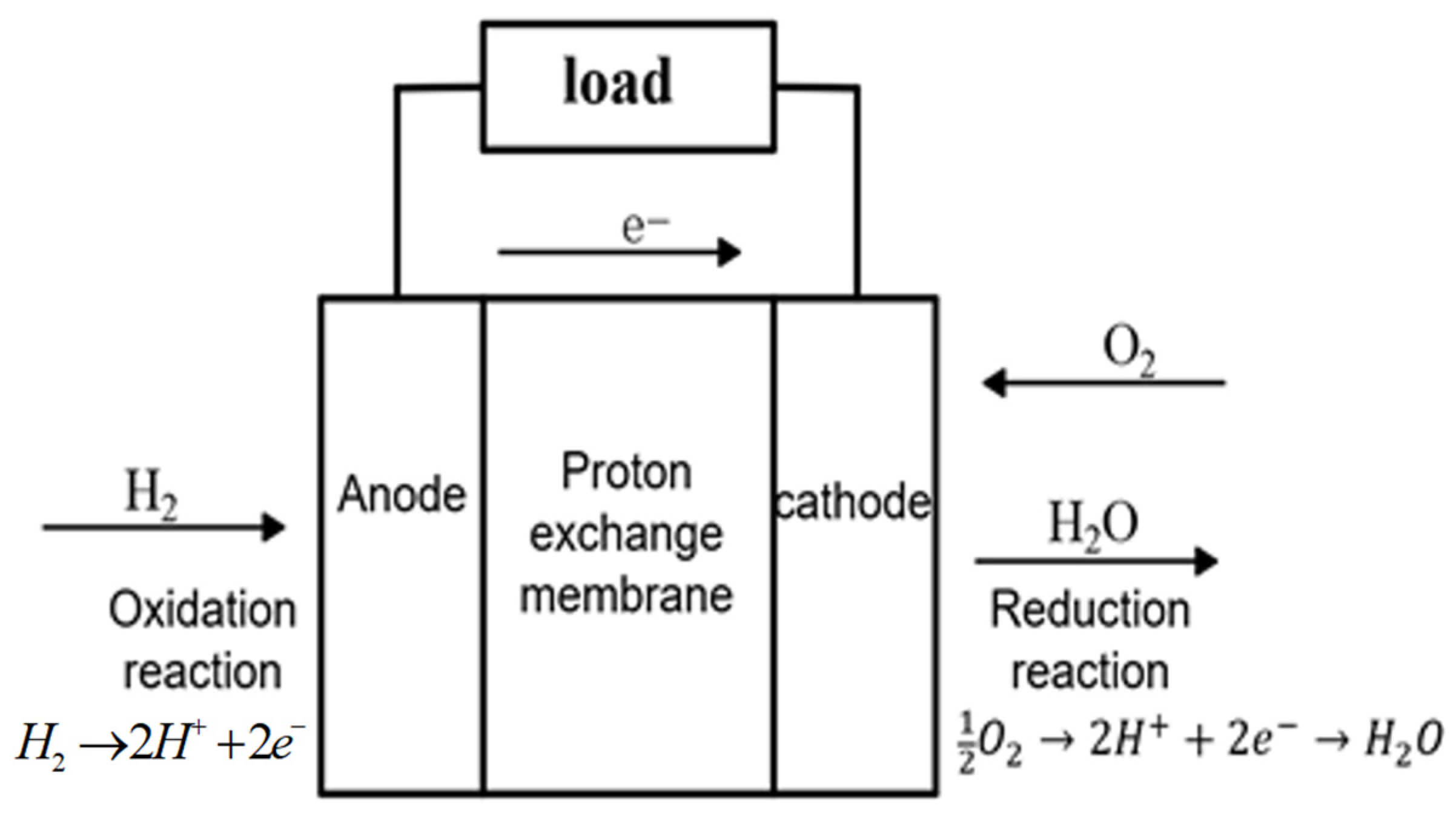
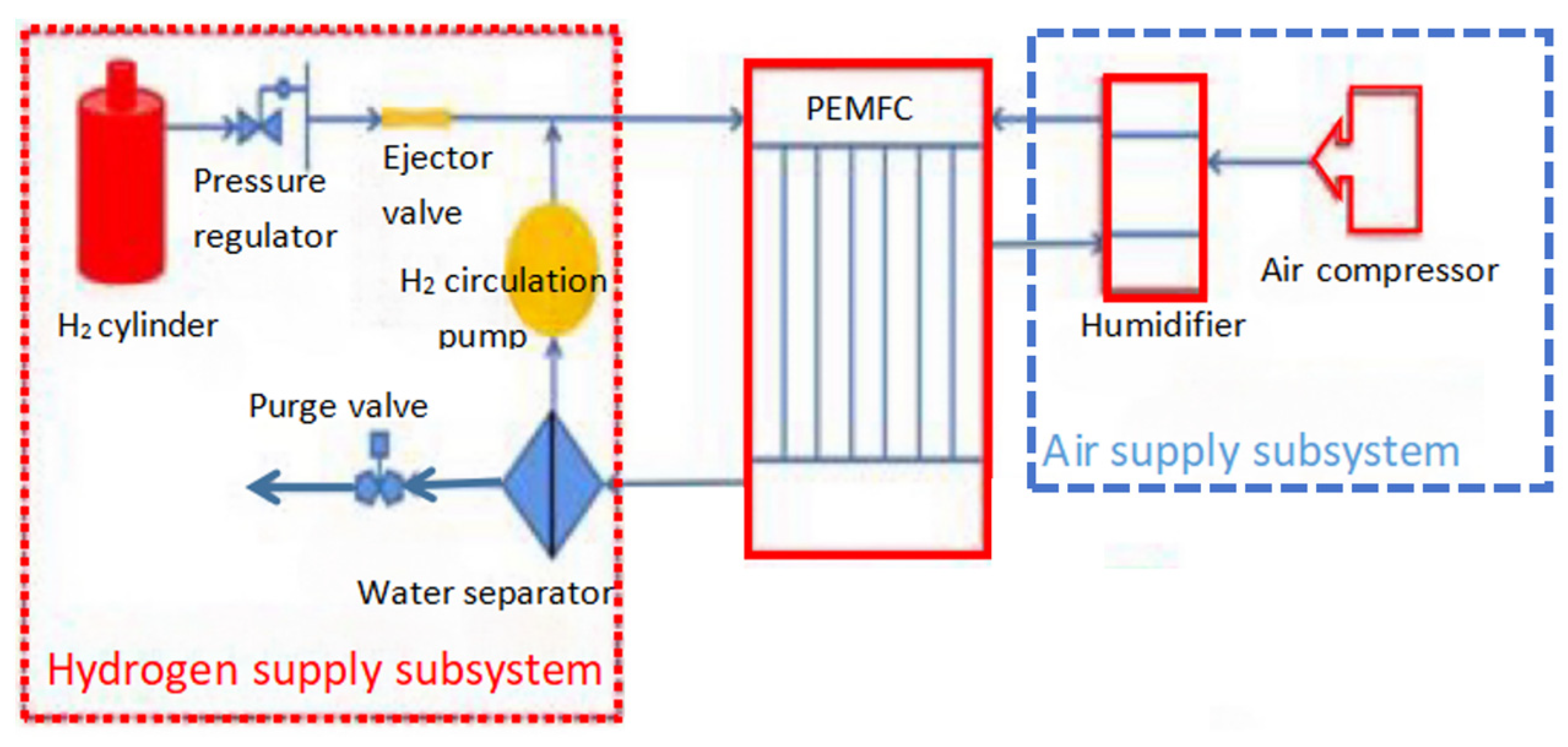
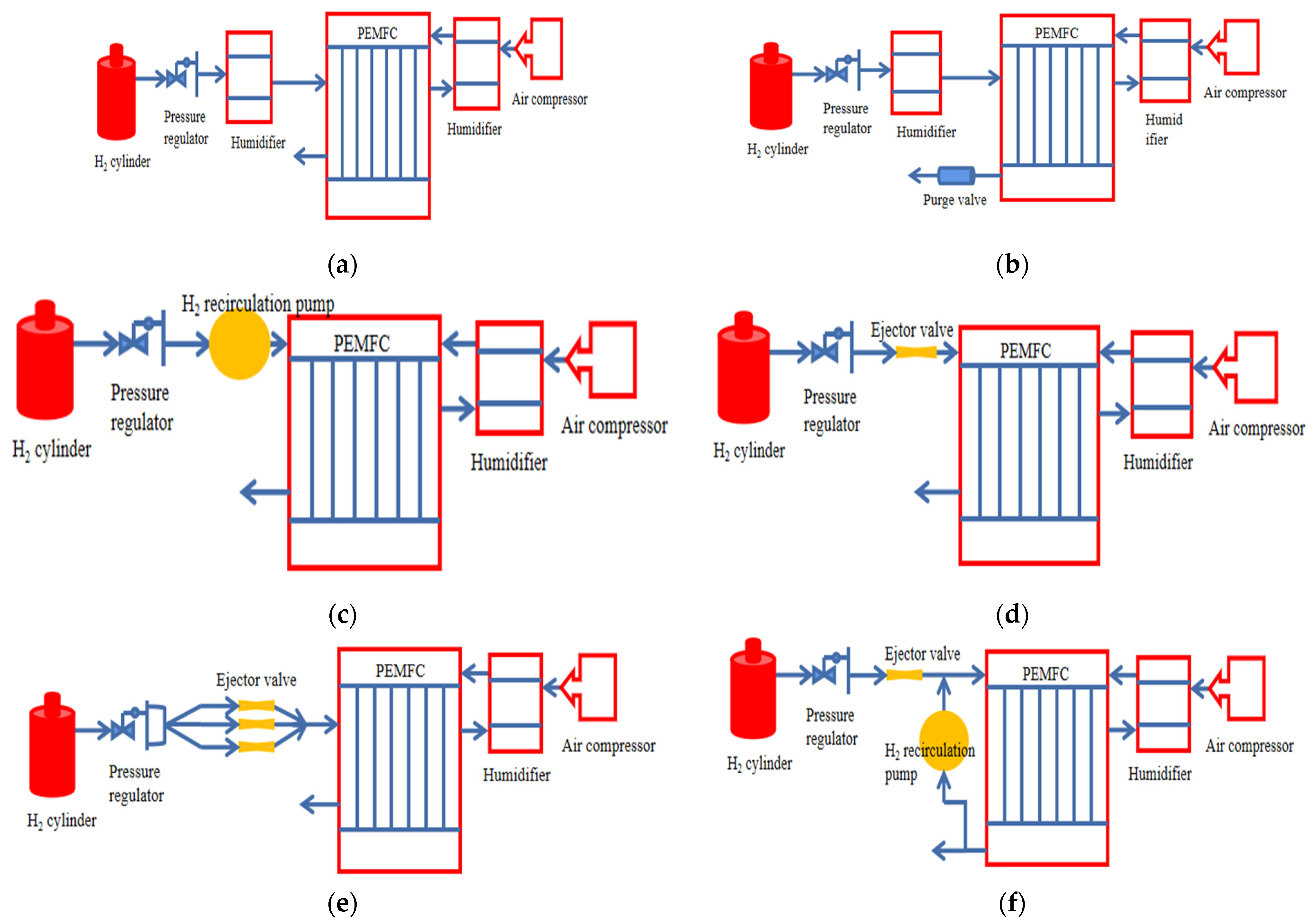
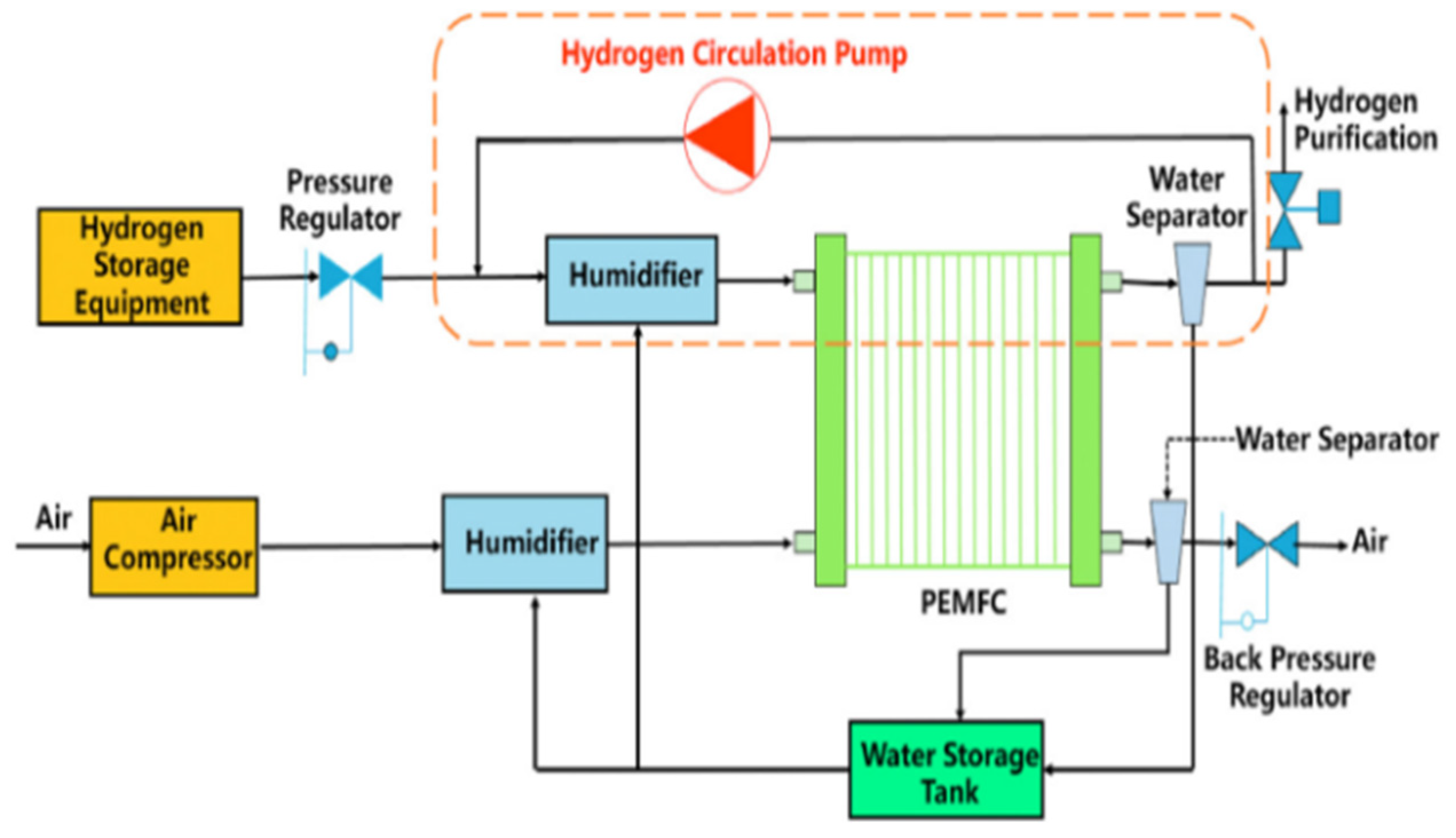
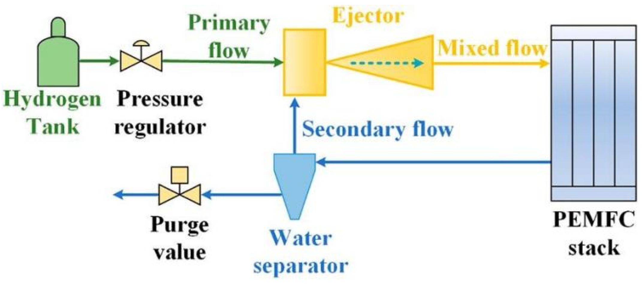
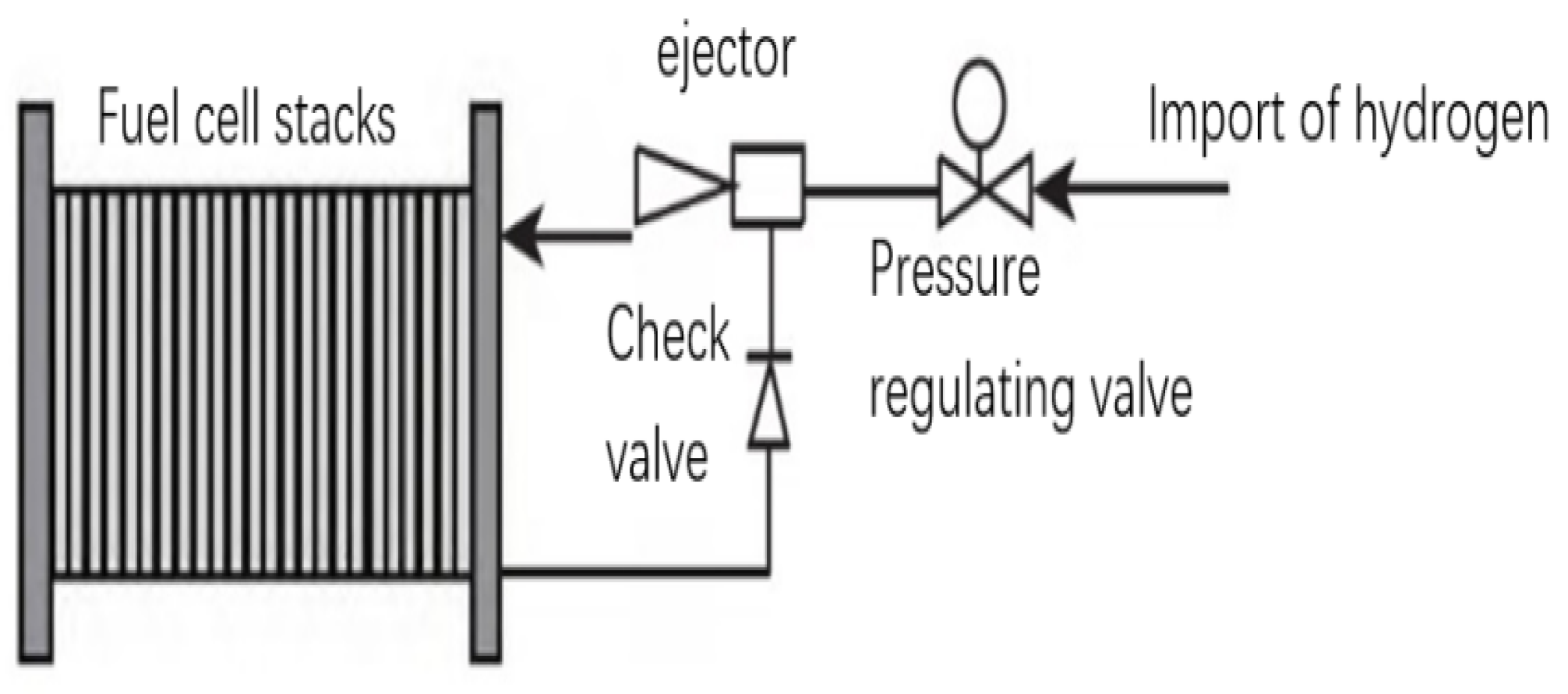
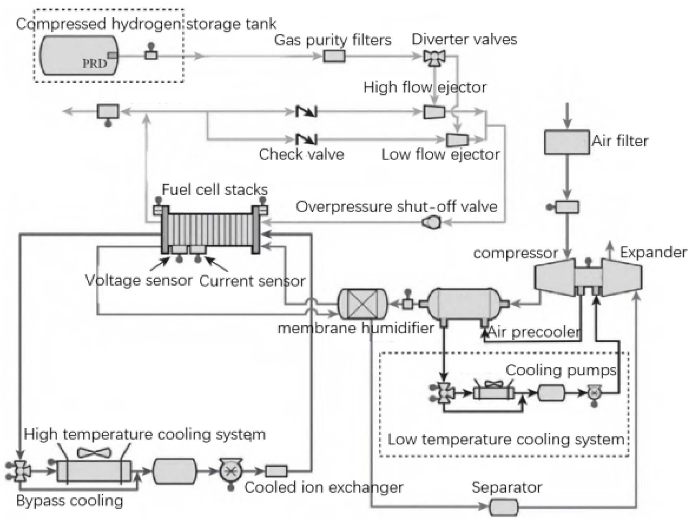
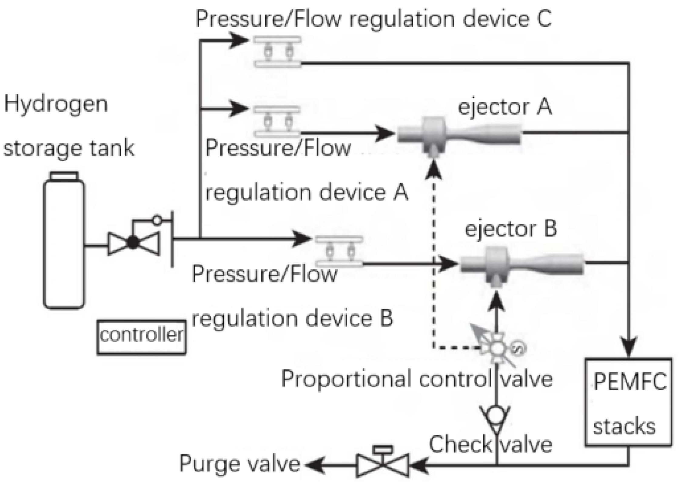
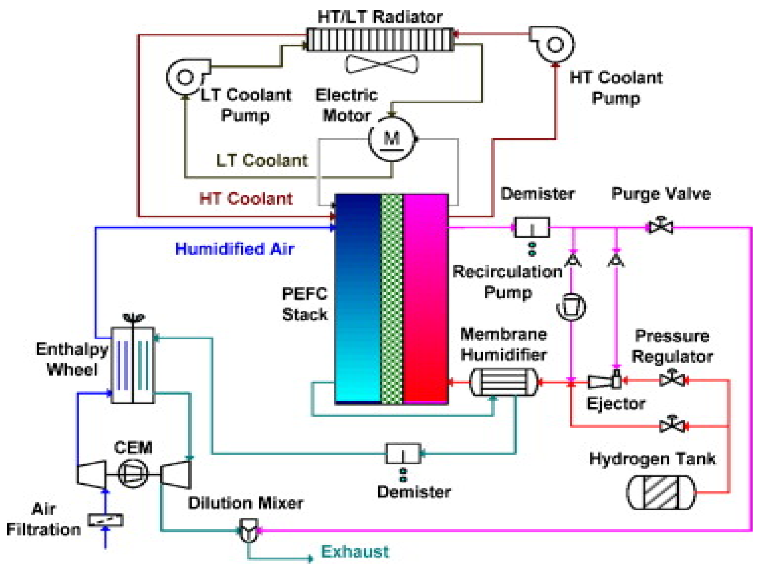
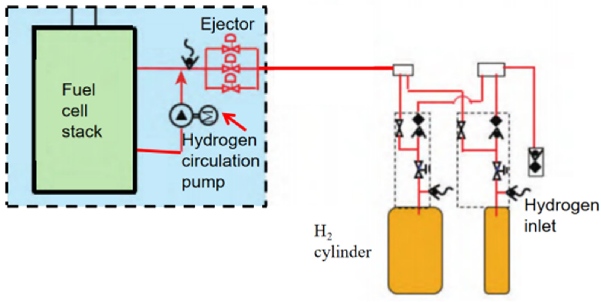
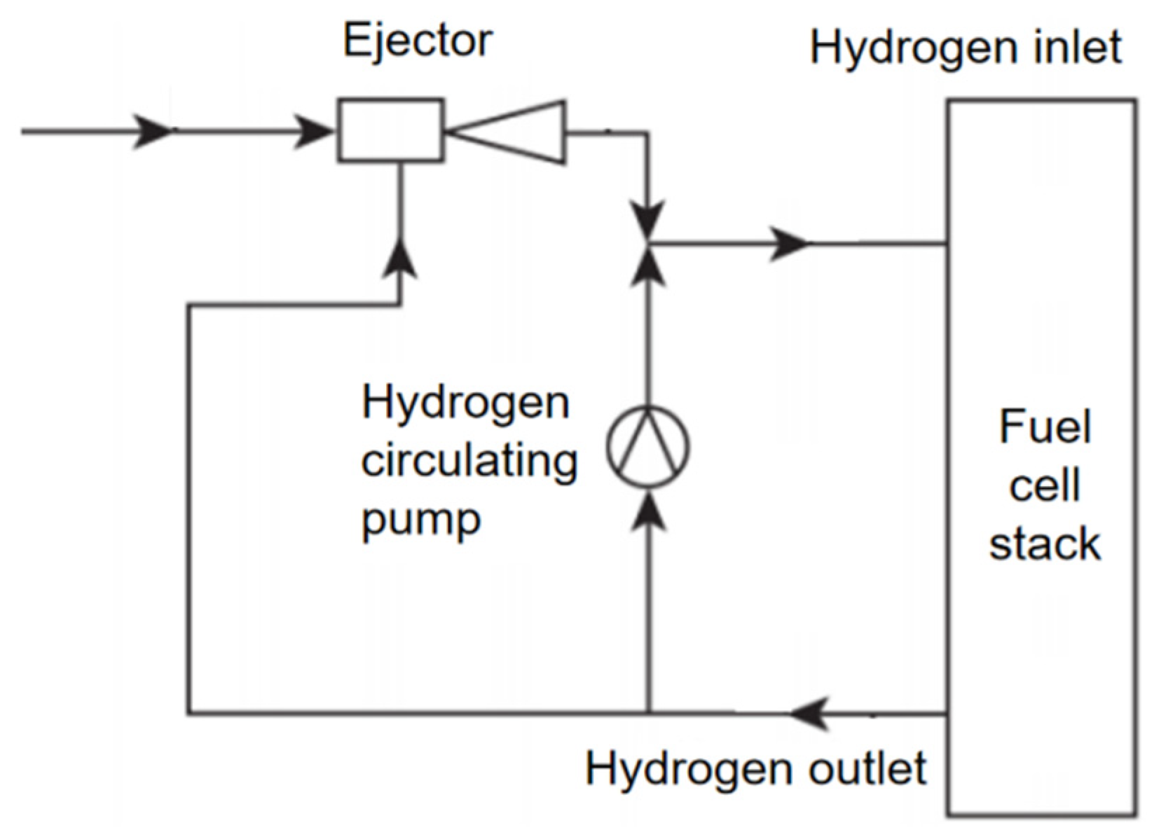
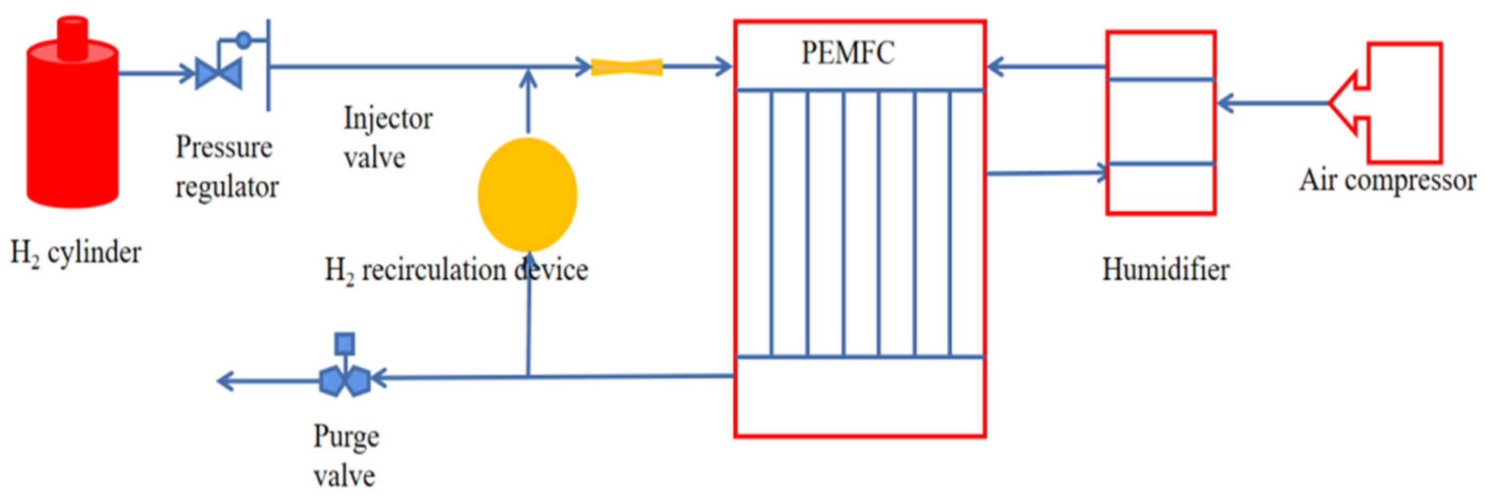

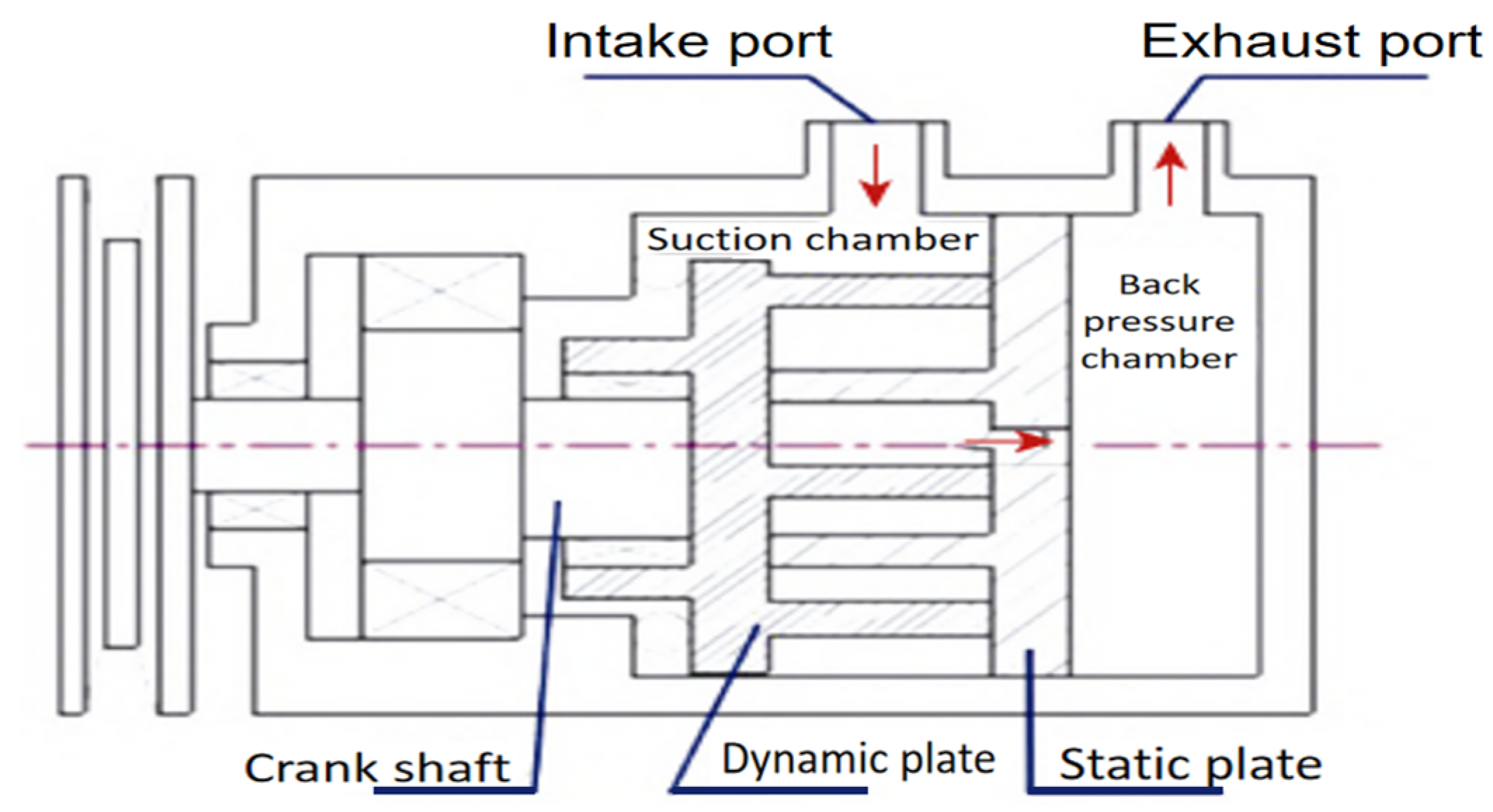

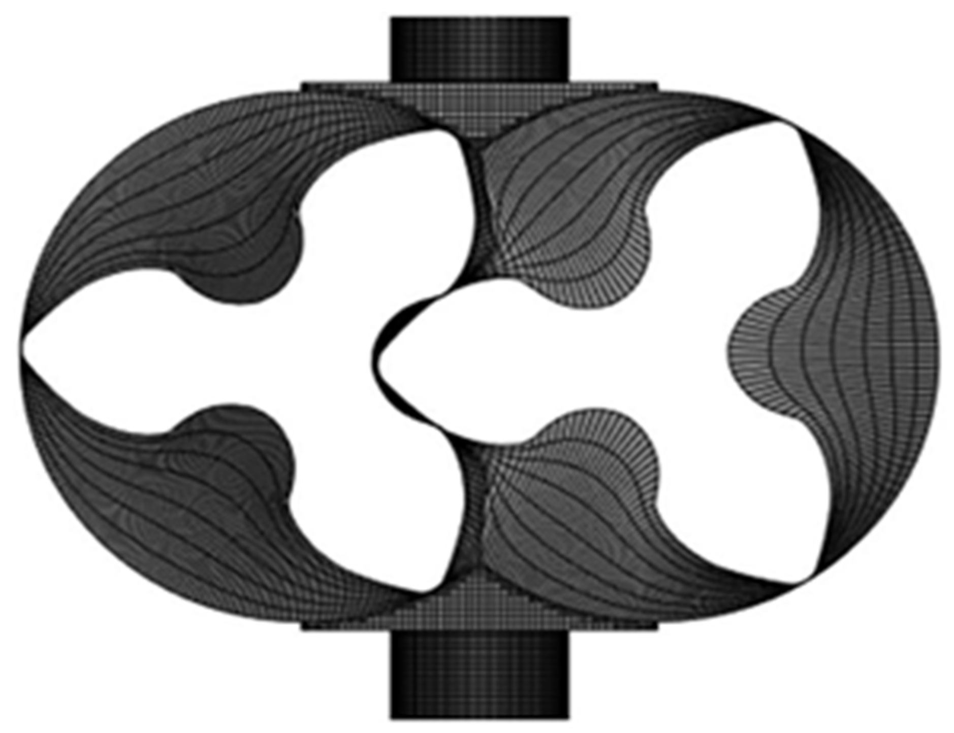
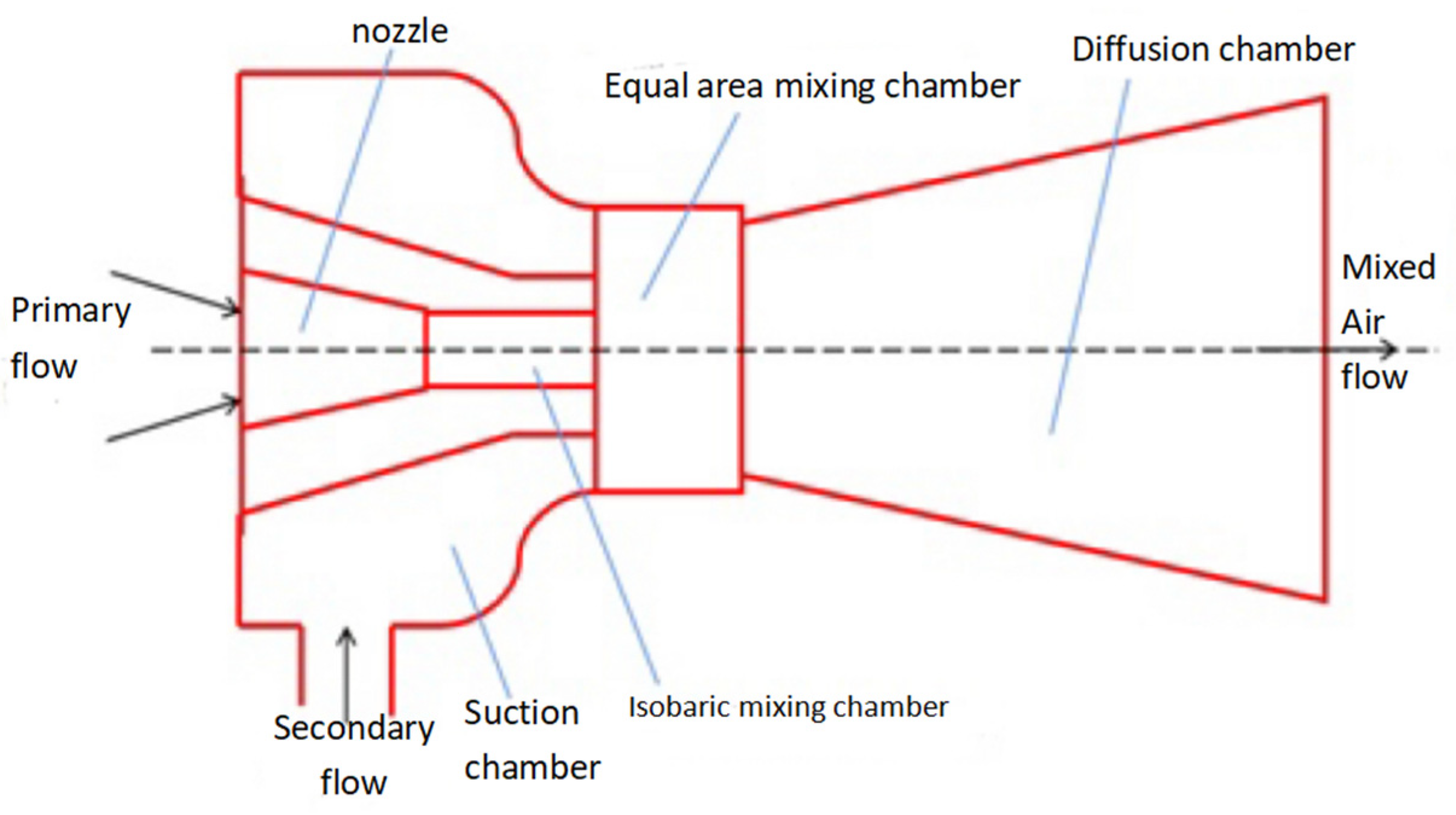
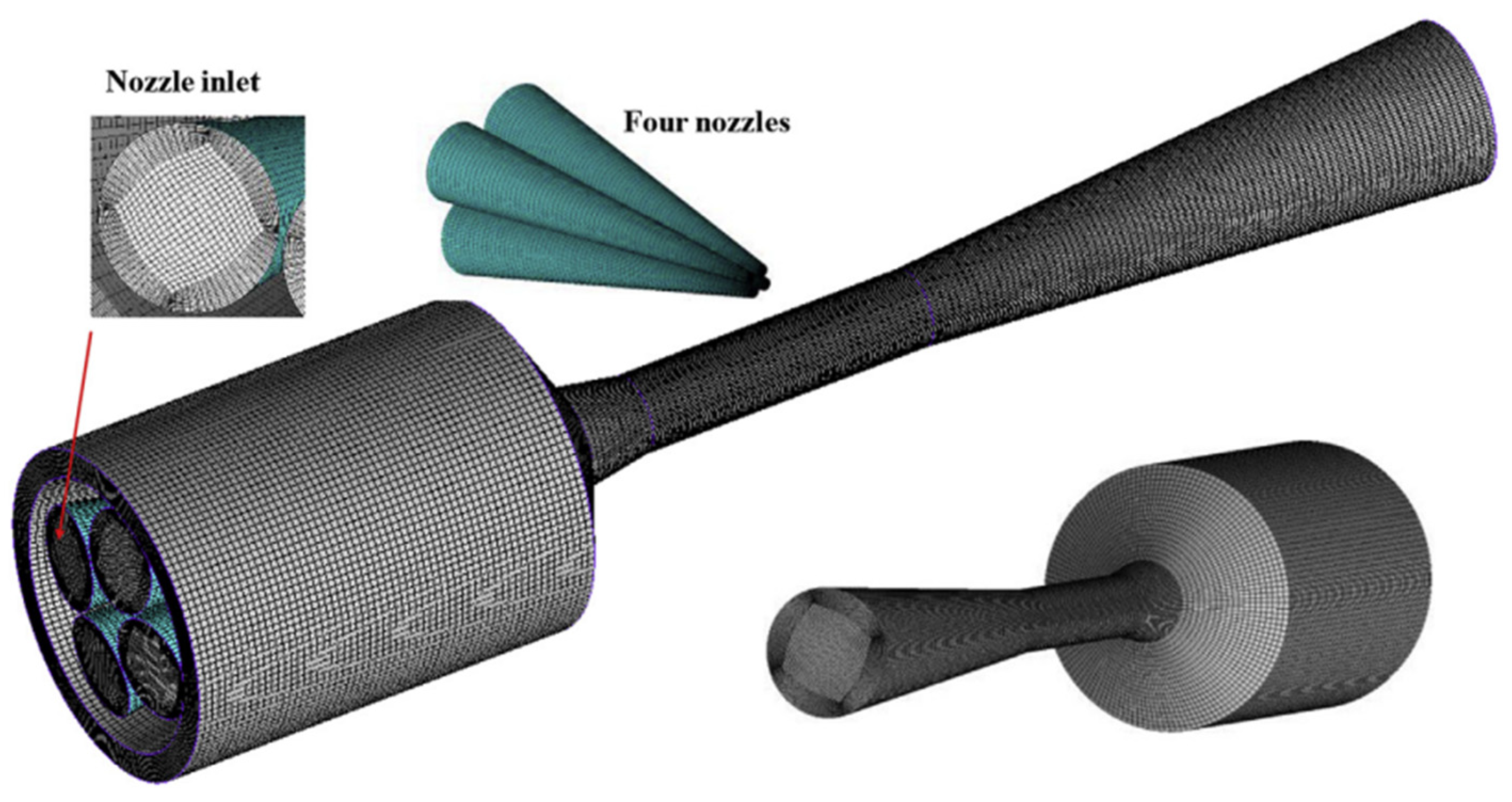
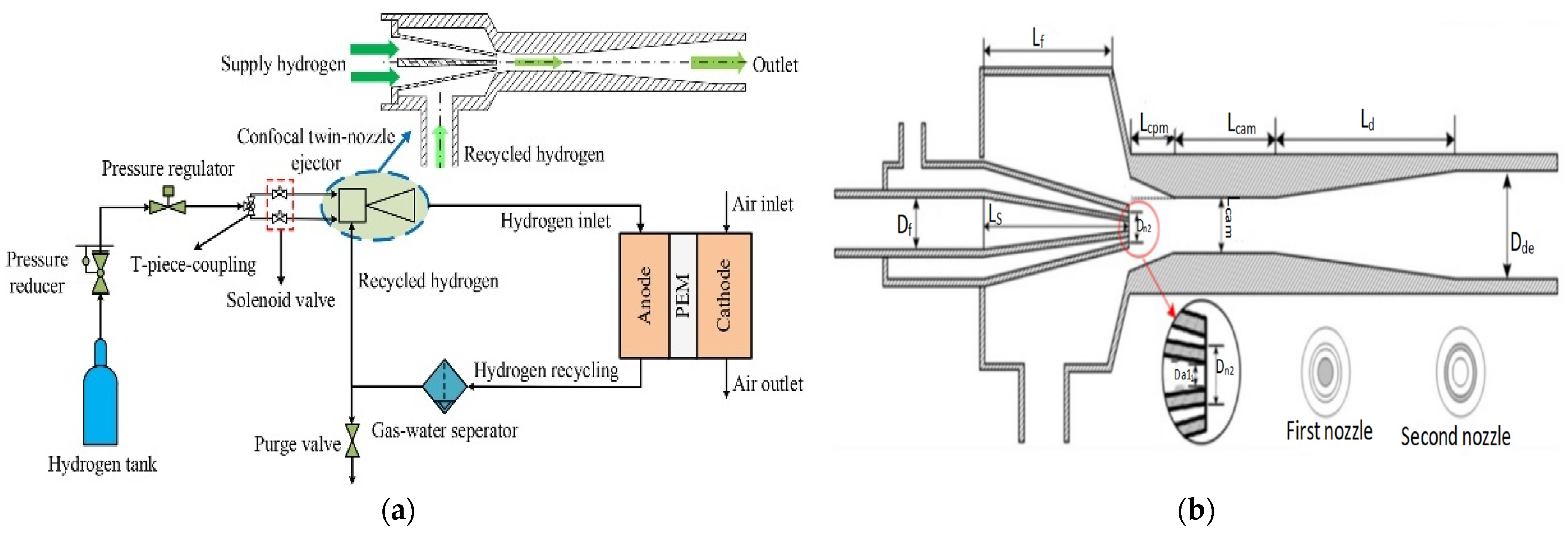
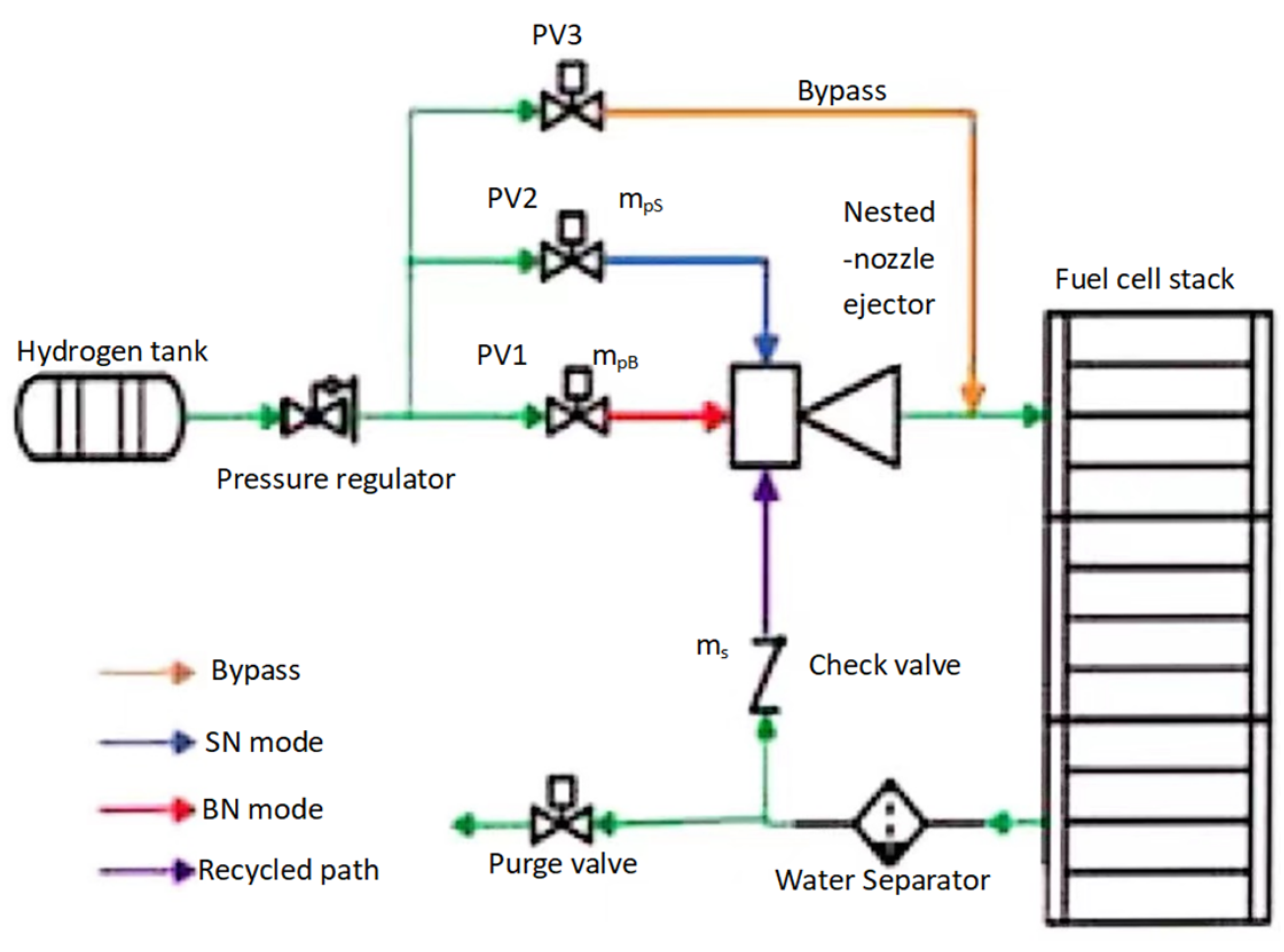
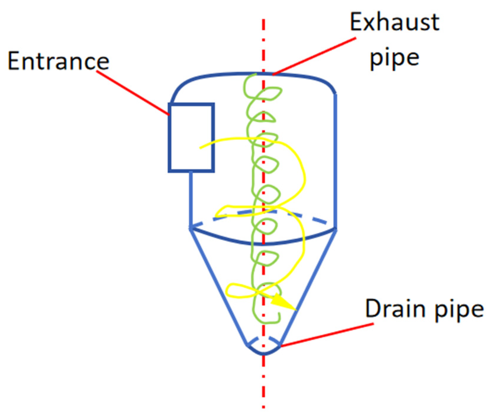
Disclaimer/Publisher’s Note: The statements, opinions and data contained in all publications are solely those of the individual author(s) and contributor(s) and not of MDPI and/or the editor(s). MDPI and/or the editor(s) disclaim responsibility for any injury to people or property resulting from any ideas, methods, instructions or products referred to in the content. |
© 2024 by the authors. Licensee MDPI, Basel, Switzerland. This article is an open access article distributed under the terms and conditions of the Creative Commons Attribution (CC BY) license (https://creativecommons.org/licenses/by/4.0/).