Article

Nano-Strand Formation via Gas Phase Reactions from Al-Co-Fe Reacted with CaF2-SiO2-Al2O3-MgO Flux at 1350 °C: SEM Study and Thermochemistry Calculations

Department of Materials Science and Metallurgical Engineering, University of Pretoria, Pretoria 0002, South Africa
*
Author to whom correspondence should be addressed.
Processes 2024, 12(7), 1342; https://doi.org/10.3390/pr12071342
Submission received: 29 May 2024 / Revised: 25 June 2024 / Accepted: 25 June 2024 / Published: 27 June 2024
(This article belongs to the Special Issue Processing, Manufacturing and Properties of Metal and Alloys)

Abstract

:
The submerged arc welding (SAW) process is operated at high temperatures, up to 2500 °C, in the arc cavity formed by molten oxy-fluoride flux (slag). These high arc cavity temperatures and the complex interaction of gas–slag–metal reactions in a small space below the arc render the study of specific chemical interactions difficult. The importance of gas phase reactions in the arc cavity of the SAW process is well established. A low-temperature (1350 °C) experimental method was applied to simulate and study the vaporisation and re-condensation behaviour of the gas species emanating from oxy-fluoride flux. Energy dispersive X-ray spectroscopy (EDX) analyses and reaction thermochemistry calculations were combined to explain the role of Al as a de-oxidiser element in gas phase chemistry and, consequently, in nano-strand formation reactions. EDX element maps showed that the nano-strands contain elemental Ti only, and the nano-strand end-caps contain Co-Mn-Fe fluoride. This indicates a sequence of condensation reactions, as Ti in the gas phase is re-condensed first to form the nano-strands and the end-caps formed from subsequent re-condensation of Co-Mn-Fe fluorides. The nano-strand diameters are approximately 120 nm to 360 nm. The end-cap diameter typically matches the nano-strand diameter. Thermochemical calculations in terms of simple reactions confirm the likely formation of the nanofeatures from the gas phase species due to the Al displacement of metals from their metal fluoride gas species according to the reaction: yAl + xMFy ↔ xM + yAlFx. The gas–slag–metal equilibrium model shows that TiO2 in the flux is transformed into TiF3 gas. Formation of Ti nano-strands is possible via displacement of Ti from TiF3 by Al to form Al-fluoride gas.

1. Introduction

Submerged arc welding (SAW) is a high-heat-input welding process mainly applied to join thick steel plates [1]. The arc is struck between the continuously fed weld wire and the welded steel plate. The welding arc is shielded beneath a layer of oxy-fluoride flux to contain the arc heat and keep air from entering the welding process [1]. High temperatures of 2000 °C to 2500 °C are achieved in the arc cavity beneath the molten oxy-fluoride slag layer [2,3]. The oxides in the oxy-fluoride slag are decomposed in the high-temperature arc plasma of the arc cavity to release oxygen gas [4,5,6]. The importance of gas phase reactions in the arc cavity of the SAW process is well established [6,7,8]. Recent modelling work highlighted the role of gas phase reactions in SAW [9,10,11]. Specifically, gas–slag–metal phase interaction as influenced by Al powder was demonstrated in the aluminium-assisted alloying of the weld metal with different combinations of metal powders [10,11,12,13]. The role of Al as a de-oxidiser element is to lower the partial oxygen pressure in the arc cavity gas phase and, consequently, at the slag-weld pool interface [10,11,12,13]. The presence of oxy-fluoride nano-strands in cavities inside the post-weld slag confirmed that gases formed from the oxy-fluoride slag and metal powders and that the nano-strands formed upon re-condensation of the vaporised gas species [11,12].
Thermochemical modelling in the form of a gas–slag–metal equilibrium model was applied to calculate the likely gas phase species formed in the arc cavity [9,11,13]. The gas–slag–metal equilibrium for the aluminium-assisted alloying in SAW with Co metal powder identified the following main gas species likely formed at 2500 °C: AlF, Mg, SiO, Mn, MgF, Co, MgF2, CaF2, AlF2, Na, and NaF [13]. The gas–slag–metal equilibrium calculated without any metal powder additions for the same flux material applied in [13] identified the following likely main gas species formed at 2000 °C: CO, Na, NaF, CaF2, MgF2, MgF, AlF3, AlF2, NaAlF4, TiF3, KAlF4, and minor gas species at less than one volume% as K, KF, Mg, AlF, Mn, Fe, SiF4, and SiO [9]. Therefore, adding Al exerts a significant shift in the gas species to a higher Al-fluoride gas content. The de-oxidiser effect of Al is beneficial to maintain metals of high oxygen affinity, such as Cr and Ti, in the metallic state so that these elements are not oxidised and lost to the slag phase. Similarly, the added Co metal powder is maintained in the metallic state in the presence of Al de-oxidiser, and some Co is present in the gas phase as Co vapour, as indicated in the calculated gas phase composition stated above [13].
Oxy-fluoride slags are also applied in processes outside of the field of welding. For example, a fluoride-containing oxide slag is used in continuous steel casting for high-temperature lubrication between the solidifying steel strand and water-cooled copper mould [14,15,16]. In (ESR) electro slag remelting, an oxy-fluoride slag is used to refine and shield the melting alloy [17,18,19,20]. The process temperatures in these applications are significantly lower than the 2000 °C to 2500 °C in the SAW arc cavity. Gas formation from the molten slags applied in continuous casting and ESR was identified in several previous works [14,15,16,17,18,19,20]. Increased vaporisation losses were measured with increased CaF2 in ESR-type slags and mould flux-type slags [18,19]. Typically, the mass loss is measured by a thermogravimetric analysis (TG) apparatus. ESR-type slags contain up to 30% CaF2, and mould flux slags contain 4–10% CaF2 [18,19]. Likely, gas phase species formed from CaF2-CaO-Al2O3-MgO-TiO2 ESR slags reacted at 1000 °C to 1500 °C were calculated from thermochemistry as CaF2, MgF2, AlOF, and AlF3 [18]. Vaporisation loss increased with increased %CaF2 in slags containing 4–9% CaF2, combined with binary slags of CaO-SiO2, MgO-SiO2, and Al2O3-SiO2 reacted at 1400 °C to 1600 °C [19]. This trend was ascribed to lower SiO2 activity in the slags, leading to higher vaporisation loss via SiF4 gas formation. A slight decrease in mould flux vaporisation was measured with increased %Al2O3 (10–30% Al2O3) at 16% CaF2 at 1400 °C [15]. In contrast, in ESR slag, the vaporisation extent increased with increased TiO2 in CaF2-CaO-Al2O3-MgO-Li2O-TiO2 slag, which reacted from 1470 °C to 1530 °C [17]. Thermochemical calculations confirmed AlF3 and CaF2 as the main gas species, with increased AlF3 formation calculated for increased TiO2 addition to the slag [17]. Contrasting observations were reported for CaF2-CaO-Al2O3-(TiO2) slag in the observation of higher vaporisation loss in the absence of TiO2 [20]. Zaitsev et al. [16] reported the gas species in the vaporisation loss gas, formed from the mould flux heated from room temperature to 1527 °C, and identified the following main gas species: NaF, KF, SiF4, AlF3, and CaF2. These studies on oxy-fluoride slags show that CaF2 input fluoride material is volatilised at relatively low temperatures compared to the high temperatures in the SAW arc cavity at 2000 °C to 2500 °C [2,3]. Nano-strands were not identified in any of these studies on oxy-fluoride slags because the slags were not studied by SEM at all, or only as 2D polished sections (two-dimensional samples), which prevented the identification of 3D (three-dimensional) features, as in [20]. The high temperatures in the SAW arc cavity and the complex interaction of gas–slag–metal reactions in a small space below the arc render the study of specific chemical interactions difficult.
Therefore, this work aims to apply a low-temperature experimental technique that can be used to study the gas phase reactions emanating from the oxy-fluoride slag reaction with metal powders, similar to those in the SAW process. Identification of nano-strand formation in the low-temperature reaction of the welding flux and added Al-Co-Fe metal powders will confirm that the same phenomenon occurs as identified in the high-temperature conditions of SAW, namely oxy-fluoride vaporisation and re-condensation. In previous works by the authors, this work’s experimental technique, which was applied to an Al-Cr-Fe metal powder reacted with flux at 1350 °C, showed oxy-fluoride nano-strand formation [21]. The same methods applied to Al-Ti-Fe metal powders showed the formation of numerous Ti-containing oxy-fluoride nano-strands of coarser morphology [22]. These results show that each alloying metal forms different gas species when reacting with the oxy-fluoride slag and require new experimental investigation.

2. Materials and Methods

2.1. Materials

The welding flux applied as the precursor to the oxy-fluoride slag was used in prior welding research, with its phase chemical behaviour well described [23]. Upon melting, the flux forms a two-phase slag consisting of an oxy-fluoride matrix glass with spinel crystals as the secondary phase. The chemical composition of the flux is summarised in Table 1, with the iron oxide expressed as Fe2O3. The raw flux consists of agglomerate particles of 0.2–1.6 mm. Pure metal powders of Al, Fe, and Co were sourced as Al (99.7% Al, −1 mm) supplied by Sigma-Aldrich (Johannesburg, South-Africa), Fe (96.0% Fe, −50 µm) provided by Merck (Johannesburg, South Africa), and Co (99.9% Co, −150 µm) supplied by Sigma-Aldrich (Johannesburg, South-Africa).
The Fe powder represents the Fe added from the weld wire in the arc cavity, where gas phase reactions predominate. The Al is added as a de-oxidiser element, and the Co is added as the weld metal alloying element. This combination of Al and Co metal powders was demonstrated in prior welding experiments, and the role of gas phase reactions in the SAW process was explained [11,13].

2.2. Methods

The experimental procedure was designed to investigate the low-temperature (1350 °C) chemical interaction of oxides, fluorides, and metals previously applied in aluminium-assisted alloying in the SAW process [11,13]. The same experimental setup and procedures used in this work were applied to the authors’ previous works on the low-temperature vaporisation of Ti and Cr from oxy-fluoride slag at 1350 °C, and the details are as follows [21,22]. The reaction furnace is a muffle furnace, and its temperature is controlled by a PID (proportional–integral–derivative) controller connected to an S-type thermocouple as a temperature measurement instrument. The sample consisted of a dry-pressed cylindrical pellet containing the reactants of flux and the metal powders Al, Fe, and Co. The mixed reactants of 19.5 g were dry-mixed and pressed into a cylindrical pellet of 20 mm in diameter and 30 mm in height. The metal powder additions were eight mass% of each. The muffle furnace temperature was maintained at 1350 °C for 12 h before starting the experiment to ensure that the furnace was soaked to 1350 °C. The pellet sample was placed onto a pellet holder plate made of 2 mm thick carbon steel and sized at 64 mm square, with a circular recessed centre to position the pellet. The pellet and holder were placed in the pre-heated muffle furnace and reacted for 6 min. On completion of this reaction time, the pellet and holder were removed from the muffle furnace to cool down in the air. Once cooled, the pellet was mechanically sectioned through its middle. One half of the pellet was coated with gold and studied using a scanning electron microscope (SEM) to identify and analyse nanofeatures in the three-dimensional (3D) sample. The SEM equipment consisted of a Zeiss (Oberkochen, Germany) crossbeam 540 FEG (field emission gun) SEM with an energy dispersive X-ray spectroscopy (EDX) probe operated at 20 kV.

3. Results

The formation of nanostructures in the cavities of the 3D slag samples from SAW post-weld slags was previously confirmed. SEM work was performed on the post-weld slags generated in welding experiments using the same flux as applied here, with various combinations of added Al, Co, Cu, Ni, and Cr metal powders [11,13].
Therefore, in this work, the search for nanofeatures was also concentrated on the slag cavity features. Figure 1a displays the low-magnification (×147) SEM image of the 3D slag structure with multiple cavities formed in the pellet sample reacted at 1350 °C. The EDX element maps of the field of view (FOV) in Figure 1a are displayed in Figure 1b. The oxy-fluoride matrix that forms the cavity walls consists of Al-Mg-Ca-Si-Fe-Mn-Na-K-Ti oxy-fluoride. This composition of elements includes all the main elements present in the raw flux (Table 1). The Table 1 analysis is displayed in Table 2 for comparison to the average EDX analyses of the FOV in each Figure. It is seen that the Figure 1 FOV analysis is similar to the raw flux analysis, with a somewhat lower Ca content at 6.5% Ca vs. 9.3% Ca. Figure 1b shows that fluoride spheres of less than 100 μm in diameter contain the elements Co, Mn, and Fe. This effect is noticeable because Co was added to the experiment as a pure metal powder of −150 μm in size. Therefore, the incorporation of this Co into the Co-Mn-Fe fluoride spheres indicates a separate transport path to simply dissolution into the oxy-fluoride matrix.
Figure 2 shows the blocked area in Figure 1a at a higher magnification of (×1390) to better view the 3D features in this FOV. The element maps in Figure 2b confirm that the Co-Mn-Fe-containing sphere is fluoride-based, contains Si, and does not contain oxygen. Multiple finer spheres containing Co-Mn-Fe-Si-F appear in the cavity wall. Titanium is erratically distributed throughout the FOV, as shown in Figure 2. The analyses in Table 2 indicate a lower %Ca for Figure 2b compared to Figure 1b. The blocked area of the cavity wall in Figure 2a is shown at a larger magnification (×7820) in Figure 3. The nanofeatures of sphere-capped nano-strands are better visible in Figure 3. The EDX element maps in Figure 3b show that the cavity wall matrix phase consists of Al-Mg-Ca-Si-Na oxy-fluoride, the nano-strands consist only of Ti, and the spheres at the end of the nano-strands consist of Co-Mn-Fe fluoride. The absence of other elements in the nano-strands differs from prior observations of oxy-fluoride nano-strands in similar experiments with Al-Fe-Cr and Al-Fe-Ti metal powder additions [21,22]. The observation of nano-strand end-cap spheres is somewhat similar to that identified previously for Al-Fe-Cr metal additions in terms of Cr, Mn, and Fe concentrating in the oxy-fluoride end-cap spheres. The absence of oxygen in the Co-Mn-Fe nano-strand end-caps differs from that in the previously identified Cr-Mn-Fe-containing end-caps [21]. The latter end-caps contained the same elements as their nano-strands, namely Al-Mg-Ca-Si-Na-K-Cr-Fe-Mn-Ti oxy-fluoride. Figure 3a shows the blocked area at a higher magnification of (×26,380) in Figure 4. The EDX element maps in Figure 4b confirm the chemical differences in the oxy-fluoride wall matrix, nano-strands, and their end-caps, as discussed above for Figure 3b. The nano-strand diameters vary from approximately 120 nm in nano-strand side branches to 360 nm in diameter in the main branches, as seen in Figure 4a, and the nano-strand lengths vary from approximately 280 nm to several micrometers. Nano-strand end-cap diameters appear to match the nano-strand diameters at approximately 200 nm. The end-caps are of much larger diameter at joining branch junctions, at up to 1.6 µm in diameter.

4. Discussion

Low-temperature gas formation from oxy-fluoride slags is well established, for example, in applying fluoride-based mould powders in steel continuous casting and applying oxy-fluoride slags in (ESR) electro slag remelting [14,15,16,17,18,19,20]. Zaitsev et al. [16] conducted the most extensive study on CaF2-SiO2-CaO-Al2O3-Na2O-K2O mould flux by analysing the gas formed upon heating the mould powder. The main gas species identified were NaF formation starting at 600 °C, KF formation starting at 883 °C, SiF4 formation starting at 830 °C, AlF3 formation starting at 974 °C, and CaF2 formation starting at 1262 °C. The following gas species were also measured: NaAlF4, Na2AlF5, AlOF, and BF3. In most discussions on welding flux chemistry, the formation of fluoride gas species from CaF2 is explained by showing Reaction (1). Adding metal powders to the reaction system induces alternate reactions in the oxy-fluoride system in addition to the formation of fluoride gas species identified in the above-mentioned prior works. Therefore, Reaction (1) alone does not explain the possible gas species that may form once metal and oxy-fluoride slag react.
SiO2(slag) + 2CaF2(g) ↔ 2CaO(slag) + SiF4(g)
The phase transition temperatures of the pure fluorides in the current reaction system are summarised in Table 3 for the temperature interval of 1000 °C to 2600 °C. The information shows that several fluorides are thermodynamically stable as gases at 1350 °C: SiF4, AlF3, AlF2, AlF, FeF3, TiF4, TiF3, TiF2, and TiF. The data set in Table 3 shows CaF2 as a gas at a much higher temperature of 2531 °C. Comparison to the experimental results discussed above indicates that once an oxy-fluoride slag is formed, the gas phase formation behaviour differs from that of the pure substances since CaF2 was analysed in the low temperature gas phase by Zaitsev et al. [16].
Because Al forms highly stable fluorides, it can displace elements from less stable fluorides. Equation (2) displays the generic reaction for Al displacement from metal fluorides. The product may be AlF3, AlF2, or AlF. These Al-fluorides are in the gas phase above 1300 °C. Figure 5a–c show the Gibbs free energy calculated for Reaction (2) in transforming different metal fluorides to metal and Al-fluorides. The Gibbs free energy lines in Figure 5 were calculated in the Reaction module of FactSage 7.3, including the databases FactPS and FToxid [24].
yAl + xMFy ↔ xM + yAlFx
It is seen that the relative positions of the lines in Figure 5a–c remain mostly the same with increased temperature, except for TiF, as this line has a positive slope and, therefore, crosses the other lines at different temperatures. The more negative Gibbs free energy values in Figure 5a show that Al easily displaces the elements from their fluorides to form AlF rather than AlF2 and AlF3, as in Figure 5b,c. The most preferred displacement is in the sequence of FeF3, CoF2, FeF2, TiF4, TiF, SiF4, MnF2, TiF2, and, lastly, TiF3. Therefore, the formation of Co, Fe, Mn, Si, and Ti from Reaction (2) is possible and could explain the formation of the 3D features observed in the results, namely Co-Mn-Fe-Si fluoride spheres, Ti nano-strands, and Co-Mn-Fe containing end-caps on the nano-strands.
The limitation of the information from Figure 5 is that it is based on pure elements, which is not valid in terms of the oxy-fluoride slag formed. Therefore, the gas-slag-metal equilibrium model previously applied for SAW is used to calculate the likely gas phase species formed from the multi-phase reactions [9]. Applying this gas–slag–metal equilibrium model to the reaction system of Al-Fe-Co metal powder reacted at 1350 °C with the oxy-fluoride flux for different proportions of Co and Al results in the likely gas species formation, as summarised in Table 4.
The calculated equilibrium gas compositions for different cases of Al, Co, and Fe reacting with the flux indicate that TiF3 gas is readily formed from the small initial quantity of TiO2 in the flux. Al can displace the Ti in TiF3 to form Ti nano-strands, as Figure 3 and Figure 4 show. Nano-scale 3D oxy-fluoride structures indicate the vaporisation and re-condensation of oxy-fluorides [11,12,21,22]. Therefore, this work follows the same argument for nano-strand formation from gas re-condensation. The main difference between the current phenomena in Figure 3 and Figure 4 and the nano-strands observed in the authors’ prior work is that the nano-strands in this work seem to consist of Ti only in the strand part, whereas prior nano-strands consisted of oxy-fluorides [21,22].
Even though the values in Table 4 indicate no Fe, Si, and Co metal vapour in the gas phase, this should not be interpreted as no metal vaporisation occurrence because the values in Table 4 are for equilibrium conditions, which have the metals reporting to a mixed alloy phase of Co-Fe-Mn-Si-Ti. Thus, equilibrium composition may not have been reached at the low temperature applied in this work. Therefore, it appears that Ti in the gas phase re-condensed first to form the nano-strands and the end-caps formed from subsequent re-condensation of Co-Mn-Fe fluorides.
In conclusion, the results from this study confirm that low-temperature vaporisation and re-condensation occur in the oxy-fluoride reaction system with Al-Co-Fe metal powders, similar to that in SAW. The presence of nanofeatures provides evidence of this phenomenon.

5. Conclusions

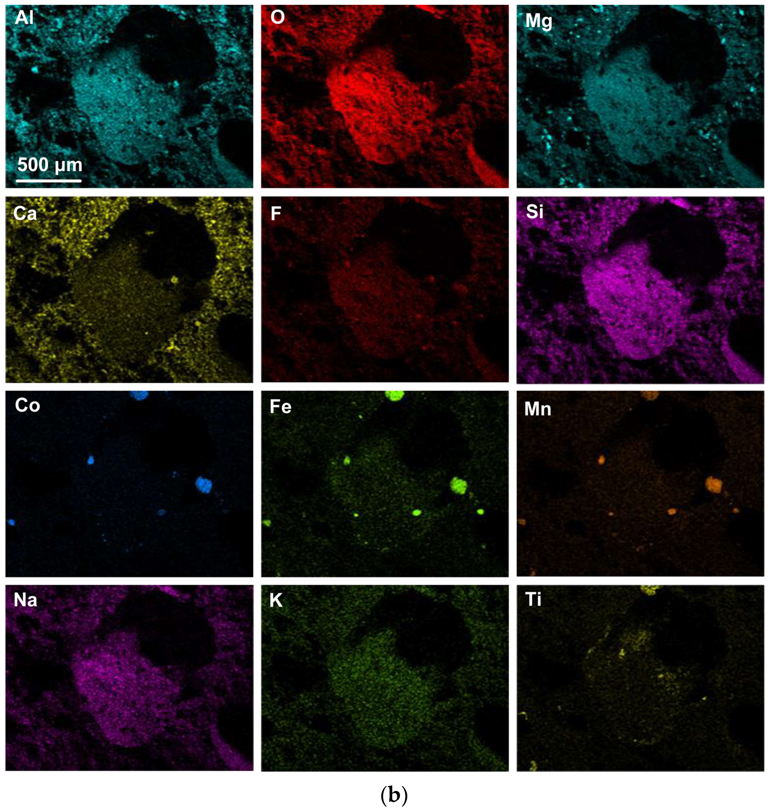
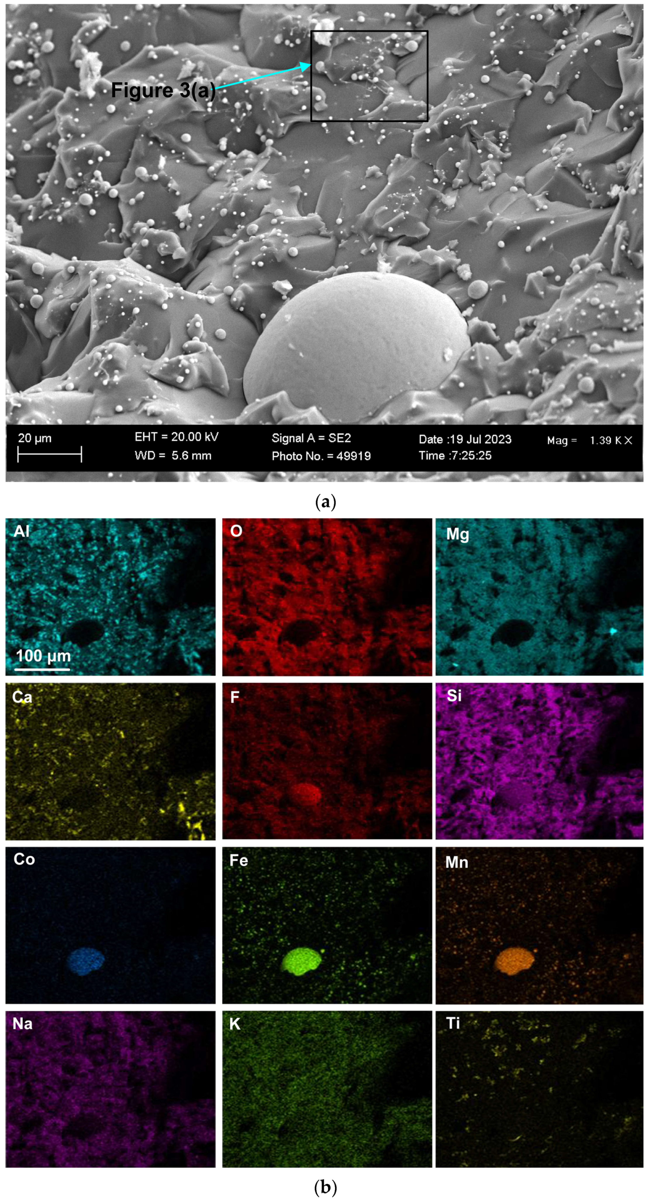
  • SEM analyses of 3D samples identified and analysed nanofeatures formed in the cavities of the oxy-fluoride slag reacted at 1350 °C with added Al-Co-Fe metal powders.
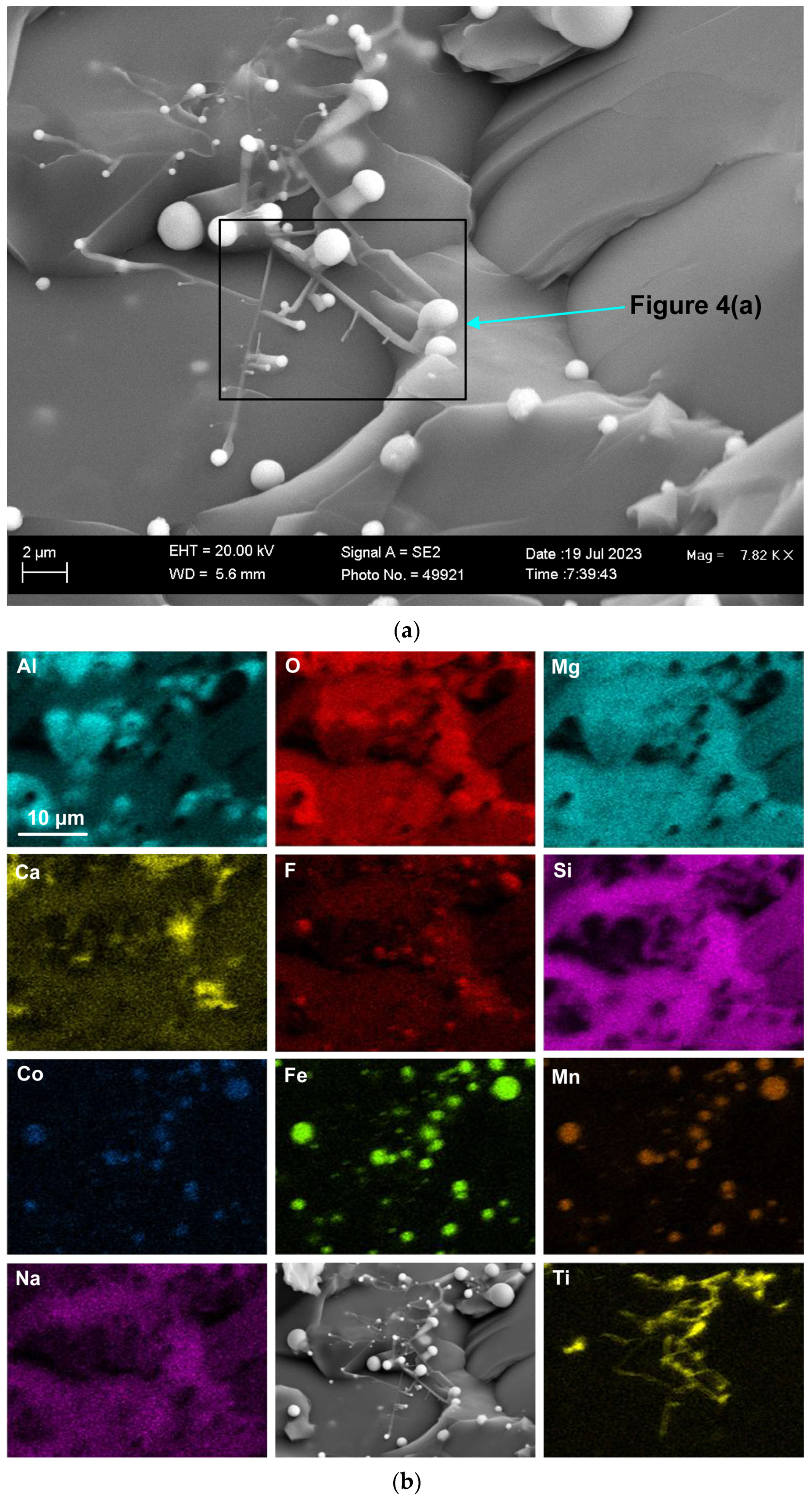
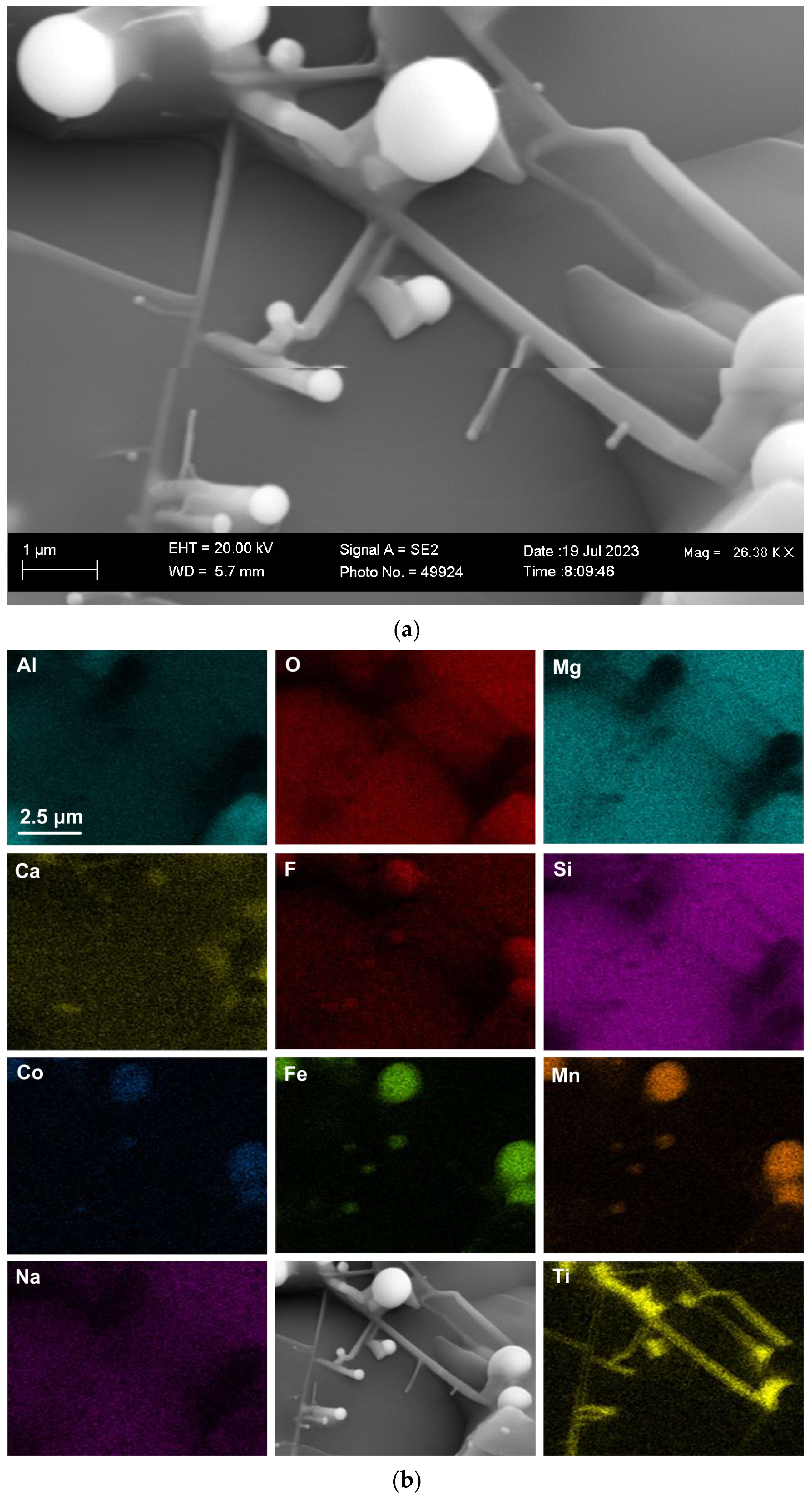
  • The nano-strands contain elemental Ti only, and the nano-strand end-caps contain Co-Mn-Fe fluoride. This indicates a sequence of condensation reactions, as Ti in the gas phase is re-condensed first to form the nano-strands and the end-caps formed from subsequent re-condensation of Co-Mn-Fe fluorides.
  • Nano-strand diameters vary from approximately 120 nm to 360 nm. Nano-strand lengths vary from approximately 280 nm to several micrometers. Nano-strand end-cap diameters appear to match the nano-strand diameters at approximately 200 nm.
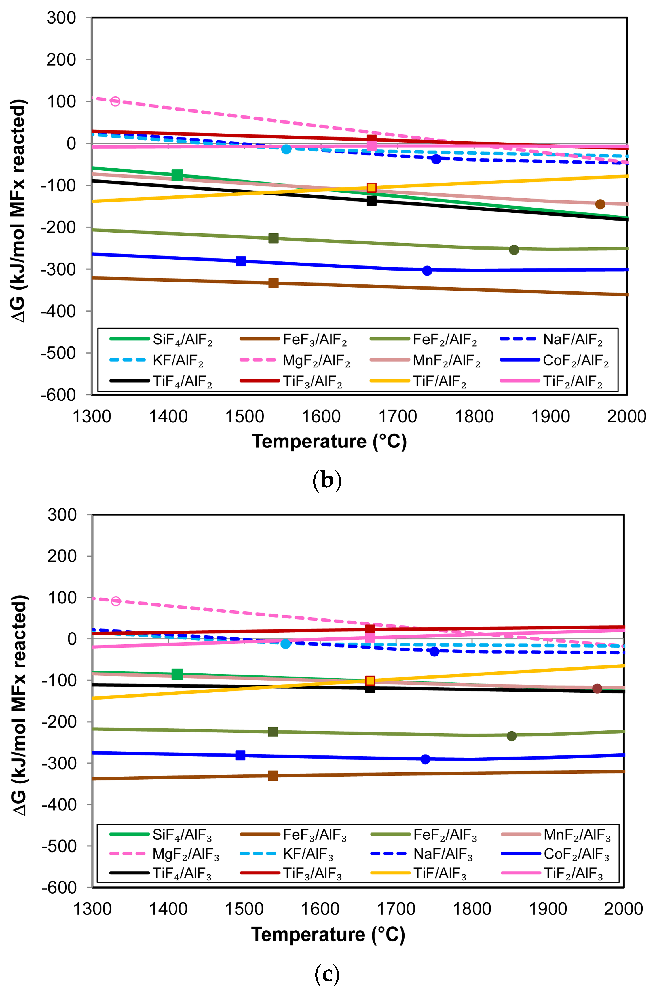
  • Thermochemical calculations in the form of simple reaction Gibbs free energy values confirm the likely formation of the nanofeatures from the gas phase species due to the Al displacement of metals from their metal fluorides gas species to form Co, Fe, Mn, Si, and Ti from the reaction: yAl + xMFy ↔ xM + yAlFx.
  • The gas–slag–metal equilibrium calculation of significant TiF3 gas formation from TiO2 in the flux material explains the formation of Ti nano-strands. The Ti is displaced from TiF3 by Al, and this Ti can form nano-strands upon re-condensation.

Author Contributions

F.D.B. conceptualised the work; F.D.B. and T.C. executed the experiments together, interpreted the data together, and prepared the manuscript together. All authors have read and agreed to the published version of the manuscript.

Funding

This research was funded in part by the University of Pretoria.

Data Availability Statement

The data sets presented in this study are available upon reasonable request to the corresponding author, as indicated on the first page.

Acknowledgments

The authors are grateful to Erna van Wilpe and Coenraad Snyman at the Laboratory for Microscopy and Microanalysis at the University of Pretoria for their advice and assistance on SEM imaging and analysis in this work.

Conflicts of Interest

The authors declare no conflicts of interest. The funders had no role in the design of the study, in the collection, analysis, or interpretation of data, in the writing of the manuscript, or in the decision to publish the results.

Nomenclature

Abbreviations
SAWsubmerged arc welding
ESRelectro slag remelting
TGthermogravimetric analysis
3Dthree-dimensional
2Dtwo-dimensional
PIDproportional-integral-derivative
SEMscanning electron microscope
FEGfield emission gun
EDXenergy dispersive X-ray spectroscopy
FOVfield of view
Symbols
σstandard deviation
(g)gas
(l)liquid
(s)solid
(slag) dissolved in slag
x, ystoichiometric factor

References

  1. Sengupta, V.; Havrylov, D.; Mendex, P.F. Physical phenomena in the weld zone of submerged arc welding—A Review. Weld. J. 2019, 98, 283–313. [Google Scholar]
  2. Chai, C.S.; Eagar, T.W. Slag-metal equilibrium during submerged arc welding. Metall. Trans. B 1981, 12, 539–547. [Google Scholar] [CrossRef]
  3. Mitra, U.; Eagar, T.W. Slag-metal reactions during welding: Part I. Evaluation and reassessment of existing theories. Metall. Trans. B 1991, 22, 65–71. [Google Scholar] [CrossRef]
  4. Chai, C.S.; Eagar, T.W. Slag metal reactions in binary CaF2-metal oxide welding fluxes. Weld. J. 1982, 61, 229–232. [Google Scholar]
  5. Polar, A.; Indacochea, J.E.; Blander, M. Electrochemically generated oxygen contamination in submerged arc welding. Weld. J. 1990, 69, 68–74. [Google Scholar]
  6. Lau, T.; Weatherly, G.C.; Mc Lean, A. The sources of oxygen and nitrogen contamination in submerged arc welding using CaO-Al2O3 based fluxes. Weld. J. 1985, 64, 343–347. [Google Scholar]
  7. Lau, T.; Weatherly, G.C.; Mc Lean, A. Gas/Metal/Slag reactions in Submerged Arc Welding using CaO-Al2O3 based fluxes. Weld. J. 1986, 65, 31–38. [Google Scholar]
  8. Gött, G.; Gericke, A.; Henkel, K.-M.; Uhrlandt, D. Optical and spectroscopic study of a submerged arc welding cavern. Weld. J. 2016, 95, 491–499. [Google Scholar]
  9. Coetsee, T.; Mostert, R.J.; Pistorius, P.G.H.; Pistorius, P.C. The effect of flux chemistry on element transfer in Submerged Arc Welding: Application of thermochemical modelling. J. Mater. Res. Technol. 2021, 11, 2021–2036. [Google Scholar] [CrossRef]
  10. Coetsee, T.; De Bruin, F. Reactions at the molten flux-weld pool interface in submerged arc welding. High Temp. Mater. Process. 2021, 40, 421–427. [Google Scholar] [CrossRef]
  11. Coetsee, T.; De Bruin, F. EERZ (Effective Equilibrium Reaction Zone) Model of Gas-Slag-Metal Reactions in the Application of Unconstrained Al-Ni-Cr-Co-Cu Metal Powders in Submerged Arc Welding: Model and 3D Slag SEM Evidence. Processes 2023, 11, 2110. [Google Scholar] [CrossRef]
  12. Coetsee, T.; De Bruin, F. Insight into the Chemical Behaviour of Chromium in CaF2-SiO2-Al2O3-MgO Flux Applied in Aluminium-Assisted Alloying of Carbon Steel in Submerged Arc Welding. Minerals 2022, 12, 1397. [Google Scholar] [CrossRef]
  13. Coetsee, T.; De Bruin, F. Application of Unconstrained Cobalt and Aluminium Metal Powders in the Alloying of Carbon Steel in Submerged Arc Welding: Thermodynamic Analysis of Gas Reactions. Appl. Sci. 2022, 12, 8472. [Google Scholar] [CrossRef]
  14. Schulz, T.; Lychatz, B.; Haustein, N.; Janke, D. Structurally based assessment of the influence of fluorides on the characteristics of continuous casting powder slags. Metall. Trans. B 2013, 44, 317–327. [Google Scholar] [CrossRef]
  15. Gao, J.; Wen, G.; Liu, Q.; Tan, W.; Tang, P. Effect of Al2O3 on the fluoride volatilization during melting and ion release in water of mould flux. J. Non-Cryst. Solids 2015, 409, 8–13. [Google Scholar] [CrossRef]
  16. Zaitsev, A.I.; Leites, A.V.; Litvina, A.D.; Mogutnov, B.M. Investigation of the mould powder volatiles during continuous casting. Steel Res. 1994, 65, 368–374. [Google Scholar] [CrossRef]
  17. Ju, J.; Ji, G.; An, J.; Tang, C. Effect if TiO2 on fluoride evaporation from CaF2-CaO-Al2O3-MgO-Li2O-(TiO2) slag. Ironmak. Steelmak. 2020, 48, 109–115. [Google Scholar] [CrossRef]
  18. Ju, J.; Gu, Y.; Zhang, Q.; He, K. Effect of CaF2 and CaO/Al2O3 ratio on evaporation and melting characteristics of low-fluoride CaF2-CaO-Al2O3-MgO-TiO2 slag for electroslag remelting. Ironmak. Steelmak. 2023, 50, 13–20. [Google Scholar] [CrossRef]
  19. Persson, M.; Seetharaman, S.; Seetharaman, S. Kinetic studies of fluoride evaporation from slags. ISIJ Int. 2007, 47, 1711–1717. [Google Scholar] [CrossRef]
  20. Shi, C.; Cho, J.; Zheng, D.; Li, J. Fluoride evaporation and crystallization behavior of CaF2-CaO-Al2O3-(TiO2) slag for electroslag remelting of Ti-containing steels. Int. J. Miner. Metall. Mater. 2016, 23, 627–636. [Google Scholar] [CrossRef]
  21. Coetsee, T.; De Bruin, F. Low temperature vaporisation of Cr from fluoride flux reacted at 1350 °C with Al–Cr–Fe powder: Thermochemical analysis of gas phase reactions and nano-strand formation. J. Mater. Res. Technol. 2024, 30, 1159–1171. [Google Scholar] [CrossRef]
  22. Coetsee, T.; De Bruin, F. Nano-strand formation in CaF2-SiO2-Al2O3-MgO flux reacted at 1350 °C with Al-Ti-Fe powder: SEM analyses and gas reaction thermochemistry. J. Solid State Chem. 2024, 331, 124547. [Google Scholar] [CrossRef]
  23. Coetsee, T. Phase chemistry of Submerged Arc Welding (SAW) fluoride based slags. J. Mater. Res. Technol. 2020, 9, 9766–9776. [Google Scholar] [CrossRef]
  24. Bale, C.W.; Bélisle, E.; Chartrand, P.; Decterov, S.A.; Eriksson, G.; Gheribi, A.E.; Hack, K.; Jung, I.-H.; Kang, Y.-B.; Melançon, J.; et al. Reprint of: FactSage thermochemical software and databases, 2010–2016. Calphad 2016, 55, 1–19. [Google Scholar] [CrossRef]
Figure 1. (a) SEM image at (147×) magnification of oxy-fluoride flux containing cavities with embedded 3D structures; (b) EDX maps of the FOV (field of view) in (a).
Processes 12 01342 g001aProcesses 12 01342 g001b
Figure 2. (a) SEM image at (1390×) magnification of 3D structure as marked in Figure 1a; (b) EDX maps of the FOV (field of view) in (a).
Processes 12 01342 g002
Figure 3. (a) SEM image at (7820×) magnification of nanofeatures marked in the blocked area marked in Figure 2a; (b) EDX maps of the nanofeatures in (a).
Processes 12 01342 g003
Figure 4. (a) SEM image at (26,8380×) magnification showing nanofeatures in the blocked area marked in Figure 3a; (b) EDX maps of nanofeatures in (a).
Processes 12 01342 g004
Figure 5. (a) Gibbs free energy of element displacement via Reaction (2) with AlF(g) formation; (b) Gibbs free energy of element displacement via Reaction (2) with AlF2(g) formation; (c) Gibbs free energy of element displacement via Reaction (2) with AlF3(g) formation. All figures: open circle = MxOy(s) → MxOy(l); filled circle = MFX(l) → MFX(g); filled square = M(s) → M(l); dashed line = M(g).
Processes 12 01342 g005aProcesses 12 01342 g005b
Table 1. Bulk chemical composition of flux (mass%).
%MnO%CaO%SiO2%Al2O3%CaF2%MgO%Fe2O3%TiO2%Na2O%K2O
7.00.120.225.718.522.92.71.01.70.2
Table 2. Average EDX field of view (FOV) analyses in Figure 1, Figure 2, Figure 3 and Figure 4.
Figure%O%F%Na%Mg%Al%Si%K%Ca%Ti%Co%Mn%Fe
Figure 137.18.21.914.214.19.20.46.50.90.64.22.5
Figure 235.57.82.314.813.611.70.82.81.10.45.03.9
Figure 337.47.72.314.413.711.70.92.22.20.23.93.0
Figure 437.38.72.814.39.113.81.21.93.40.23.73.4
Maximum σ0.230.120.030.100.090.080.010.030.020.030.040.04
Flux35.38.70.613.413.29.20.29.30.60.05.34.2
Table 3. Metal fluoride phase transition temperatures from 1000 °C to 2600 °C (FactSage 7.3): (g) = gas; (l) = liquid; (s) = solid.
FluorideGas Phase (s) → (l)(s) → (g)(l) → (g)FluorideGas Phase (s) → (l)(s) → (g)(l) → (g)
SiF4(g) CaF2 1419 2531
AlF3 1291 MnF2 1965
AlF2(g) FeF2 1852
AlF(g) FeF3(g)
CoF2 1729 TiF4(g)
MgF2 1331 2263TiF3 1035
KF 1554TiF2 1103
NaF 1750TiF(g)
Table 4. Gas composition (volume %) calculated in a gas–slag–metal equilibrium model in FactSage 7.3.
Caseg. Alg. Cog. Fe%KAlF4%NaAlF4%TiF3%SiF4%AlF3%SiF3%Mn%Fe%Si%Co
140052.222.811.88.81.71.30.05000
244054.721.813.46.71.40.80.04000
344456.719.916.54.31.10.40.03000
484478.117.70.30.90.70.30.02000
Disclaimer/Publisher’s Note: The statements, opinions and data contained in all publications are solely those of the individual author(s) and contributor(s) and not of MDPI and/or the editor(s). MDPI and/or the editor(s) disclaim responsibility for any injury to people or property resulting from any ideas, methods, instructions or products referred to in the content.

