Article

Bioactive and Topographically-Modified Electrospun Membranes for the Creation of New Bone Regeneration Models

by
Dina Abdelmoneim
1,†,
Ghsaq M. Alhamdani
1,2,†,
Thomas E. Paterson
1,3,
Martin E. Santocildes Romero
1,
Beatriz J. C. Monteiro
1,
Paul V. Hatton
1,* and
Ilida Ortega Asencio
1,*
1
Bioengineering and Health Technologies Group, the School of Clinical Dentistry, University of Sheffield, Sheffield S10 2TA, UK
2
School of Dentistry, University of Alkafeel, Najaf 54001, Iraq
3
Department of Automatic Control and Systems Engineering, University of Sheffield, Sheffield S1 3JD, UK
*
Authors to whom correspondence should be addressed.
These authors have contributed equally to this work.
Processes 2020, 8(11), 1341; https://doi.org/10.3390/pr8111341
Submission received: 30 September 2020 / Revised: 16 October 2020 / Accepted: 21 October 2020 / Published: 23 October 2020
(This article belongs to the Special Issue Biofabrication Scaffold in Regenerative Medicine)

Abstract

:
Bone injuries that arise from trauma, cancer treatment, or infection are a major and growing global challenge. An increasingly ageing population plays a key role in this, since a growing number of fractures are due to diseases such as osteoporosis, which place a burden on healthcare systems. Current reparative strategies do not sufficiently consider cell-substrate interactions that are found in healthy tissues; therefore, the need for more complex models is clear. The creation of in vitro defined 3D microenvironments is an emerging topographically-orientated approach that provides opportunities to apply knowledge of cell migration and differentiation mechanisms to the creation of new cell substrates. Moreover, introducing biofunctional agents within in vitro models for bone regeneration has allowed, to a certain degree, the control of cell fate towards osteogenic pathways. In this research, we applied three methods for functionalizing spatially-confined electrospun artificial microenvironments that presented relevant components of the native bone stem cell niche. The biological and osteogenic behaviors of mesenchymal stromal cells (MSCs) were investigated on electrospun micro-fabricated scaffolds functionalized with extracellular matrix (ECM) proteins (collagen I), glycosaminoglycans (heparin), and ceramic-based materials (bioglass). Collagen, heparin, and bioglass (BG) were successfully included in the models without modifying the fibrous structures offered by the polycaprolactone (PCL) scaffolds. Mesenchymal stromal cells (MSCs) were successfully seeded in all the biofunctional scaffolds and they showed an increase in alkaline phosphatase production when exposed to PCL/BG composites. This research demonstrates the feasibility of manufacturing smart and hierarchical artificial microenvironments for studying stem cell behavior and ultimately the potential of incorporating these artificial microenvironments into multifunctional membranes for bone tissue regeneration

1. Introduction

Over the past decade, bone-related injuries have been identified as a major global problem that have increasingly affected people’s wellbeing [1]. The number of bone fractures in northern hemisphere countries is increasing and is currently predicted to rise to 4.5 million cases by 2025 [2]. Aging populations and related illnesses including osteoporosis are closely related to this fact. Thus, the treatment of bone-based musculoskeletal injuries represents an increasing wellbeing and economic burden for national healthcare systems. Although healthy bone tissue has inherent self-healing properties, large or compromised bone defects (including non-union and infection) remain a major clinical challenge.
The gold standard treatment for bone repair is based on the use of autografts and allografts, which are subjected to associated problems, including limited availability, morbidity, and risk of infection amongst other issues. Orthobiologic therapies have also been explored for promoting bone healing and include the use of cells, genes, and proteins [3]. Despite their promising performance, they are overpriced (in part due to significant regulatory barriers) and have associated risks. Hydroxyapatite (HA) and bioactive glasses (BG) have been broadly explored and included within artificial constructs as inorganic components to encourage intrinsic osteoconductive properties, mimicking the mineral part of the native bone [4,5]. The fields of bone tissue engineering and regenerative medicine have definitely made successful progress in the design of smart biomaterials and scaffolds for bone healing in the past decades but, despite being innovative and relatively effective, these approaches do not tackle in a single step the challenges faced by the bone tissue engineering community. In essence, current models do not recreate microenvironments in which stem cells develop and coexist in vivo. Stem cells present unique self-renewal features and are known to be fundamental for repairing and maintaining tissues throughout life; their behavior is complex and regulated both by intrinsic cellular programs and extrinsic signals dictated by the surrounding environment (niche). Stem cell niches can be described as intricate microenvironments that play an important role in stem cell renewal and differentiation. The existence of stem cell niche as a physically defined environment was first proposed by Schofield in 1978 [6]. The intricate anatomy of the stem cell microenvironment as well as the complicated biochemical cues involved in its regulation make the location and identification of stem cell niches a difficult task. Stem cell niches have been identified in many different tissues such as the bulge area of hair follicles [7] and the crypt base in the intestine [8]. Likewise, corneal stem cells have been located in the limbal area of the eye [9,10] and neural stem cells are believed to reside in regions such as the subventricular zone and the hilus of the dentate gyrus [11]. Current stem cell niche paradigms suggest that a successful niche environment depends on a combination of three related elements: (1) a well-defined 3D structure, which provides some physical protection; (2) the presence of cells with stem cell capability, surrounded by specific extracellular matrix (ECM) components; and (3) the presence of stromal cells with the ability of interacting with the other cells in the niche through distinct soluble factors [12,13,14].
Mimicking the behavior of the stem cell niche is a challenging task but currently developed strategies can mimic “certain aspects of the stem cell niche” via the control of a small number of variables and the design of “artificial stem cell niches”. These studies have reported successful results including the following findings: (i) the study of primary rat mesenchymal stem cell (rMSCs) behavior [15,16] and the glial origin of MSCs [17]; (ii) the creation of neural microfabricated devices [18]; (iii) the development of artificial niche models for the study of limbal stem cell behavior [19,20,21,22]; and (iv) the study of embryonic and hematopoietic stem cell responses [23,24,25]. Mimicking the stem cell niche becomes even more challenging when it specifically targets “bones” since at least two different niches have been identified in bone marrow (osteoblastic and vascular niche respectively) [26].
In the literature, it is possible to find different approaches to mimic the bone stem cell niche by stimulating osteogenesis and consequently improving bone repair. Minardi et al. observed that human MSCs osteogenic differentiation was stimulated when cultured on nanocrystalline magnesium-doped HA/collagen type I composite scaffolds and observed that such scaffolds stimulated bone formation in a rabbit ectopic mode [27]. A different model was presented by Danti et al. by culturing multistage osteogenic hMSCs on biodegradable Poly L-lactic acid (PLLA)/gelatine spongy scaffolds. A cell population with different osteogenic differentiation stages was obtained by culturing undifferentiated cells on the scaffolds with osteogenic medium and by periodically seeding new undifferentiated MSCs (cell shots) into the same scaffold. This method allowed for the development of a stem cell niche with graded osteogenicity characteristics which presented similarities with the bone MSCs populations in in vivo niches [28].
More recently, Muerza-Cascante et al. developed melt electrospun polycaprolactone (PCL) calcium-phosphate coated and NaOH-etched scaffolds for bone repair. These scaffolds were seeded with primary human osteoblasts and placenta-derived human MSCs in osteogenic and non-osteogenic conditions in order to develop an endosteal-like tissue. As a result, endosteal ECM deposition was enhanced in osteoblasts in osteogenic conditions but not in MSCs, independently of the scaffold surface treatment [29]. Further, a study by Tang et al. focused on mimicking bone porous architecture and biological cues to be used in the regeneration of large bone defects. To achieve this, a macro/micro/nano scaffold with “sized matched entrapped” bone morphogenetic protein-2 (BMP-2) was developed. Providing osteoconductivity and osteoinductivity in different scales, the porous scaffolds managed to improve bone regeneration in vivo by stimulating ectopic bone formation in mice and bone formation in rabbits [30].
Although, as cited above, there have been attempts to mimic the complexity of the bone marrow stem cell niche using intricate 3D culture approaches [31], the reality is that the development of a functional bone stem cell microenvironment still remains a big challenge.
This project proposes the use of topographical and mechano-biological cues as tools for creating niche-like structures for studying bone regeneration. Although using topography by itself for directing cell behavior has successfully been reported [15,25], the incorporation of extracellular matrix components would allow us to create a more relevant hierarchical construct that mimics closer the mechano-biology of the native substrate. In this sense, we chose to use collagen I (Figure 1) as an example of ECM structural protein, which has also been identified in most tissues including bone [32]. We also explored the incorporation glycosaminoglycans (GAGs), specifically heparin (Figure 1), since sulphated glycosaminoglycans have demonstrated to undertake key roles in driving stem cell differentiation and have been identified both in the surfaces of animal cells and within the ECM [33].
The inorganic bone phase should also be considered when developing new models for bone healing (Figure 1) and it has been widely reported that the use of mineral-doped scaffolds shows great promise in bone tissue regeneration [34]; for example, the addition of HA in both natural and synthetic-based materials has resulted in an increase of osteogenic differentiation [35,36,37]. The use of BG as a ceramic-based phase for driving cell fate has also been reported [38,39]. The work we present here focuses on the use of this approach for scaffold biofunctionalization (specifically using BG) and relies on the use of innovative additive manufacturing techniques (AM) and conventional fabrication techniques (electrospinning).
The aim of this research was to design and manufacture a complex hierarchical membrane equipped with key niche biofunctional microenvironments that could direct cell behavior by providing a topographical and mechano-biological relevant native-like substrate. These new membranes set the basis for the future development of complex and multifunctional medical devices that can ultimately have the ability to control stem cell fate and function for aiding in bone healing.

2. Materials and Methods

2.1. Manufacture of Electrospun Membranes

Electrospinning solutions containing 10 wt % of Poly(ε-caprolactone) (PCL; average molecular weight = 80,000; Sigma-Aldrich®, Sheffield, UK) were prepared using dichloromethane (DCM; Fisher Scientific®, Sheffield, UK) and N,N-dimethylformamide (DMF; Fisher Scientific®, Sheffield, UK). The solutions were stirred overnight until homogenous. The fabrication of the electrospun mats was performed using a custom-made electrospinning machine. A Kd scientific pump was used to eject the polymer solution out of a 1 mL plastic syringe (Becton Dickinson, Sheffield, UK) through a 20-gauge blunt metallic needle. The needle was connected to an external Alpha IV Brandenburg power source, supplying an electric current. The polymer solution was delivered at a constant rate flow (3 mL/h) to a metallic collector that was connected to a voltage power supply. Upon applying a voltage of 17 kV, a fluid jet was ejected from the syringe towards the collector that was placed at a distance of 21 cm. The solvent evaporated and charged polymer fibers were deposited on the collector in the form of non-woven fibers. Scaffolds with and without microfeatures were manufactured under the same electrospinning conditions. When plain scaffolds (without included topography) were fabricated, the fibers were collected directly on a foil covering the metallic collector. Scaffolds with microfeatures (mats with incorporated 3D-topographical cues) were fabricated using stainless additive-manufacturing-designed metallic templates as previously reported [15] (see schematic in Figure 2 for clarification).

2.2. Characterization of PCL Electrospun Scaffolds Prior to Biofunctionalization

The electrospun scaffolds were characterized using a scanning electron microscope (SEM). Samples of 10–12 mm diameter were cut from each mat using a cork borer and they were mounted on aluminum stubs using double-sided adhesive conductive carbon discs. The samples were sputter-coated with gold (3 minutes’ total sputtering time) using an Edwards Sputter Coater S150B and viewed in a Philips XL- 21 SEM with an accelerating voltage of 15 kV. SEM micrographs were used to evaluate the fiber diameter of the electrospun scaffolds. Six SEM micrographs were selected for samples and fiber diameters were measured using ImageJ software. In total, 25 fibers were specifically chosen from the same area in each image by applying a grid for diameter measurement. The values were processed by calculating the average and standard deviation of the readings.

2.3. Biofunctionalisation of PCL Electrospun Scaffolds

2.3.1. Absorption of Collagen and Heparin

The electrospun membranes were sterilized by immersion in 500 μL of Isopropyl alcohol (Fisher Scientific, Sheffield, UK) for a minimum of 60 min, removed, and left to dry. Collagen at 50% in distilled water was prepared from a stock solution of 5 mg/mL in 0.1 M acetic acid and fluorescing heparin (Thermofisher, Sheffield, UK) at 20% in distilled water was prepared from a stock of 1 mg/mL. Collagen and heparin were added as a 5 µL drop inside the microfeatures and on plain electrospun scaffold controls (without synthetic niches) using an Eppendorf precision micro-pipette.

2.3.2. Incorporation of Inorganic Component (Bioactive Glass)

Bioactive glass (BG) was fabricated in house from raw materials matching the specific ratios of the original 45S5 BG composition introduced by Larry Hench (1998). The glass frit was milled for 1 h and then, to obtain the desired particle size (<45 µm), the milled BG powder was sieved through a laboratory stainless steel sieve with an aperture size of 150 µm and 45 µm (Fisher Scientific, Sheffield, UK). PCL electrospun scaffolds were manufactured using 3 different compositions of glass (0%, 10%, and 30%). The BG powder was added to the PCL pellets before being dissolved in the solvent and then stirred at room temperature for 3 h. Afterwards, 3 mL of the prepared solution were spun in each session according to the previously mentioned parameters (see Section 2.1).

2.4. Materials Characterization after Incorporation of Biofunctional Agents

Sirius red staining was used to identify location of collagen deposits. Samples were stained using a solution of 0.1% Sirius red in picric acid (Direct Red 80, C.I. 35780, Sigma-Aldrich, Sheffield, UK) for one hour and washed three times with phosphate buffered saline (PBS; Sigma Aldrich, Sheffield, UK) to clear the unbounded stain before images were taken. To identify the presence of heparin, a 0.4% (w/v) Toluidine Blue solution was prepared using 0.1 M sodium acetate buffer (pH = 9). During staining, samples were incubated for 15 min in 1 mL of staining solution and washed several times before pictures were taken. Heparin presence was identified by the dark purple staining.
Rheology studies were performed using the different polymer-glass electrospinning solutions; 1 mL of 10% PCL solution from each composition (0%, 10%, and 30% glass of the PCL weight) and 5 mL of the solvent blend were prepared. The samples were then homogenized using a magnetic stirrer for 3 h before the test. Afterwards, a shear viscosity test was performed using a Physica MCR 301 rotational rheometer with a CP 50-1cone plate, (Anton Paar, Graz, Austria). The viscosity values were recorded at the lowest measurable shear rate (2 s−1) with a force of 0.61 N, 0.1 mm gap and a temperature of 25.02 °C. A shear rate of 2 s−1 was chosen after a linear pattern indicating constant viscosity readings was observed in the 2–10 s−1 region (10 s−1 being the termination point). The shear viscosity of the PCL/BG solution (WU1) was calculated by the ratio of shear stress and corresponding shear rate as represented by Mezger 2011 [40].

2.5. Biological Assessment

2.5.1. Cell Culture

Rat MSCs were extracted from rat bone tibia as reported previously [41]. Media was composed of Dulbecco’s modified Eagle’s medium (DMEM; Sigma Aldrich, Sheffield, UK) supplemented with 10 units/mL penicillin (Sigma Aldrich, Sheffield, UK), 0.1 mg/mL streptomycin (Sigma Aldrich, Sheffield, UK), 20 Mm L-alanyl glutamine, and 5% Foetal calf serum (FCS) (Biosera, Sheffield, UK), as well as maintained in a humidified atmosphere of 5% CO2 at 37 °C. Electrospun samples were transported to a new set of 24-well plates with 1 mL of fresh culture media per well. In this study, rMSCs were used up to the 4th passage and prepared in a suspension form. Later, 1 mL of cell suspension containing 50,000 rMSC cells was added to each well. Then, the same number of cells was directly seeded on wells without any electrospun material (Tissue Culture Plastic) (TCP), to act as positive controls. Cell, BG, and protein-free controls were also prepared. The plates were incubated at a temperature of 37 °C in 5% CO2 and the cells had media removed and replaced every 3 days.

2.5.2. Cell Viability and Cell Morphology

Metabolic activity for rMSCs was assessed using the PrestoBlue® assay (Life Technologies, Sheffield, UK) according to the manufacturer’s instructions as an indicator of cell viability and proliferation at days 1, 7, and 14 of cell culture. Each sample was incubated with 700 µL of 10% (v/v) PrestoBlue® solution in cell culture media for 1 h and 30 min. After incubation the solution was transferred to a 96-well plate (200 μL solution per well) and fluorescence was measured using an Infinite 200 PRO microplate reader at 553/590 nm (Tecan, 2013) and Magellan data analysis software.
Cell morphology was assessed using SEM, fluorescence, and confocal microscopies. Scanning electron microscopy was performed after 14 days of incubation. rMSCs cultured on PCL scaffolds were fixed with 4% (v/v) glutaraldehyde solution and washed with PBS and distilled water. The sample dehydration process was performed by progressively increasing ethanol content (EtOH) (Sigma Aldrich, Sheffield, UK) in water at concentrations of 25%, 50%, 75%, 90%, and 100% (v/v); then, dehydrated scaffolds were treated with ethanol:hexamethyldisilazane solution (EtOH:HMDS; 1:1 (v/v); Sigma Aldrich, Sheffield, UK) for 1 h and finally they were treated with 100% (v/v) HMDS solution for 5 min. Before SEM imaging, HMDS was removed and the samples dried for 1 h at room temperature. Next, 24 h later, the samples were placed on double-sided carbon discs and fixed on aluminum stamps. Gold coating was performed using a S150B, Edwards sputter for 3 min before being scanned, and SEM micrographs were obtained by Philips XL 20 electron microscope. For the fluorescence study, cells were stained with 4′, 6-diamidino-2-phenylindole (DAPI; nuclei) and conjugated fluorescein isothiocyanate (FITC; actin fibers). After washing with PBS, cells were fixed with 4% (v/v) paraformaldehyde for 1 h. Prior to labelling, a solution of 0.1% (v/v) Triton-X was added to each sample for 20 min to permeabilize cell membranes and facilitate the staining process. Then, 10 mL of PBS solution with 0.1% (v/v) DAPI and 0.2% (v/v) FITC were added for 40 min at room temperature. Images were obtained using a fluorescence microscope (Axioplan 2, ZEISS) and a laser scanning microscope S10 META.

2.5.3. Alkaline Phosphatase Assay (ALP)

ALP, a marker of early osteogenic differentiation, can provide an indication of pre-osteoblastic activity. To measure ALP activity, a substrate solution was prepared by dissolving one tablet of 5-Bromo-4-chloro-3-indolyl phosphate/Nitro blue tetrazolium (BCIP-NBT, Sigma Aldrich, Sheffield, UK) in 10 mL of distilled water. rMSCs cultured scaffolds were washed with PBS, fixed with 4% (v/v) formaldehyde solution at room temperature for 60 s, and washed with 0.05% (v/v) Tween 20 in a PBS buffer solution. Afterwards, 250 μL of substrate solution were added to cover the scaffold and samples were incubated for 5–10 min. After washing with the buffer solution, samples were kept in PBS until image analysis by optical microscope (SteREO Discovery V8 microscopy). ALP was measured by calculating the percentage of the image which contained the ALP stain. Images were analyzed using ImageJ. Images underwent color threshold, set to 8 bit images, and then the threshold tool was used to set a binary color system. The entire image was then measured using “the area measure tool” to get a percentage of the ALP stain. In total, 3 images for each condition were analyzed.

2.6. Statistical Analysis

All the data is presented as a mean ± standard deviation. Data was analyzed using GraphPad Prism 7. T test (t-Test: two-sample assuming equal variances) and one-way ANOVA were used for parameter estimation and hypothesis testing, with p < 0.05 and p < 0.01 considered to be statistically significant.

3. Results

3.1. Electrospun Scaffold’s Shape, Thickness, and Fiber Morphology

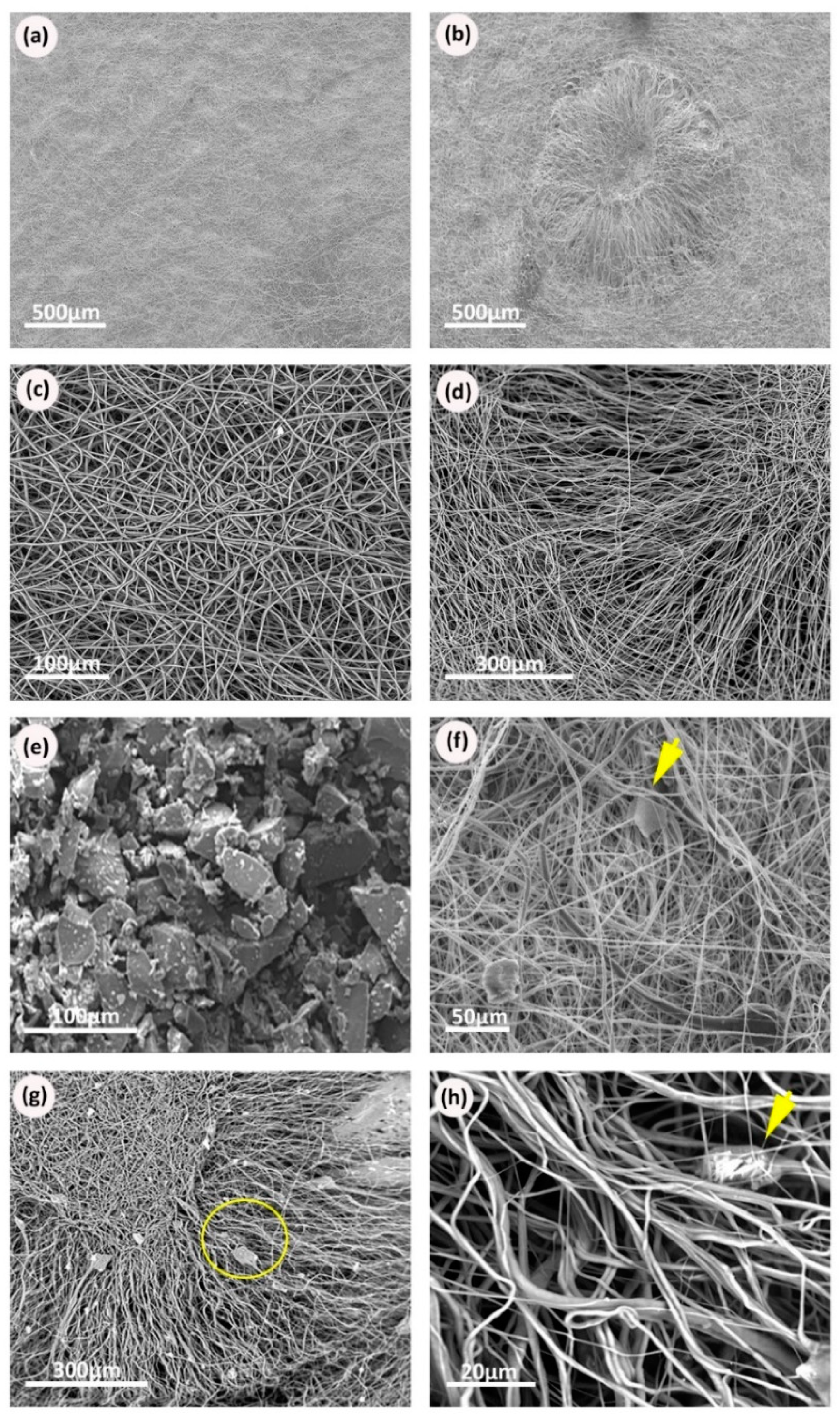
The thickness of scaffolds was measured using a digital micrometer. Scaffold thickness showed a variation between 0.1 to 0.2 mm. The diameter of the circular-cut scaffolds was also measured and ranged between 1.3 to 1.5 cm. Figure 3a,b shows low magnification images of the plain and scaffolds with niches. Both scaffolds were observed to have a 3D structure with interconnected voids and randomly oriented fibers. At a very high magnification, the fiber morphology appeared to be homogenous and clearly formed a uniform 3D surface (Figure 3c). The synthetic model of a niche appeared to be a confined cavity with a higher edge than the surrounding environment. At the edge of the niche fibers were of lower density and were more aligned (Figure 3d,e). SEM pictures for samples with PCL/BG glass compositions (10% and 30% BG) showed regions of increased diameter and irregular shape confirming the BG particles where present within the mat (Figure 3f–h).
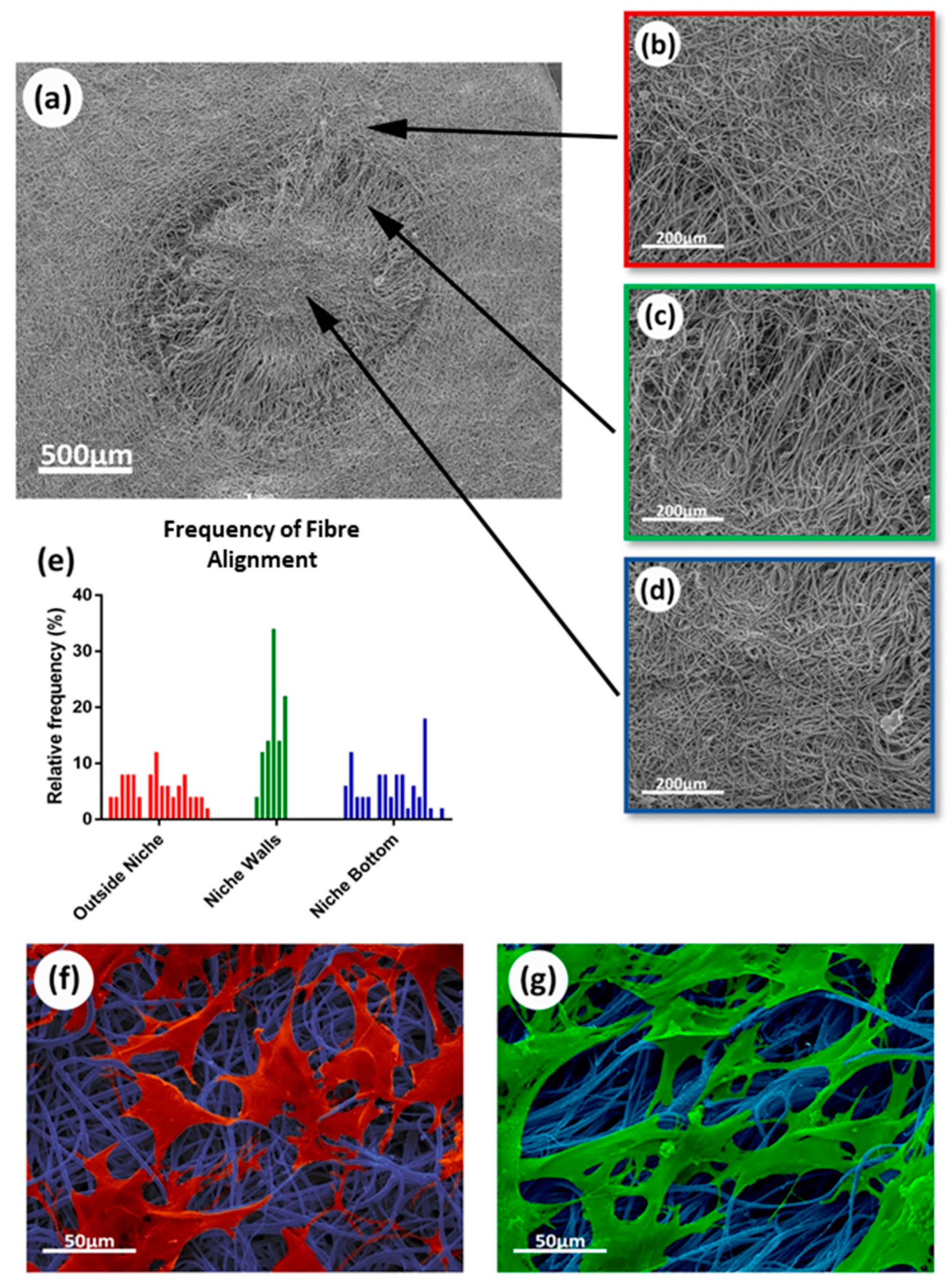
The morphology of the niche-like structures was also characterized using SEM (Figure 4a). Areas with different fiber alignments were identified within the synthetic niches (Figure 4b–d), which were characterized using ImageJ. Significant differences in alignment were found between the fibers forming the niche walls and the fibers in the top and bottom of the niche (Figure 4e); these differences in alignment resulted in changes in cell morphology (see SEM colored images in Figure 4f,g) with rMSCs presenting a more elongated phenotype when growing on the aligned niche walls.

3.2. Rheological Properties for Bioglass-Doped Electrospinning Solutions

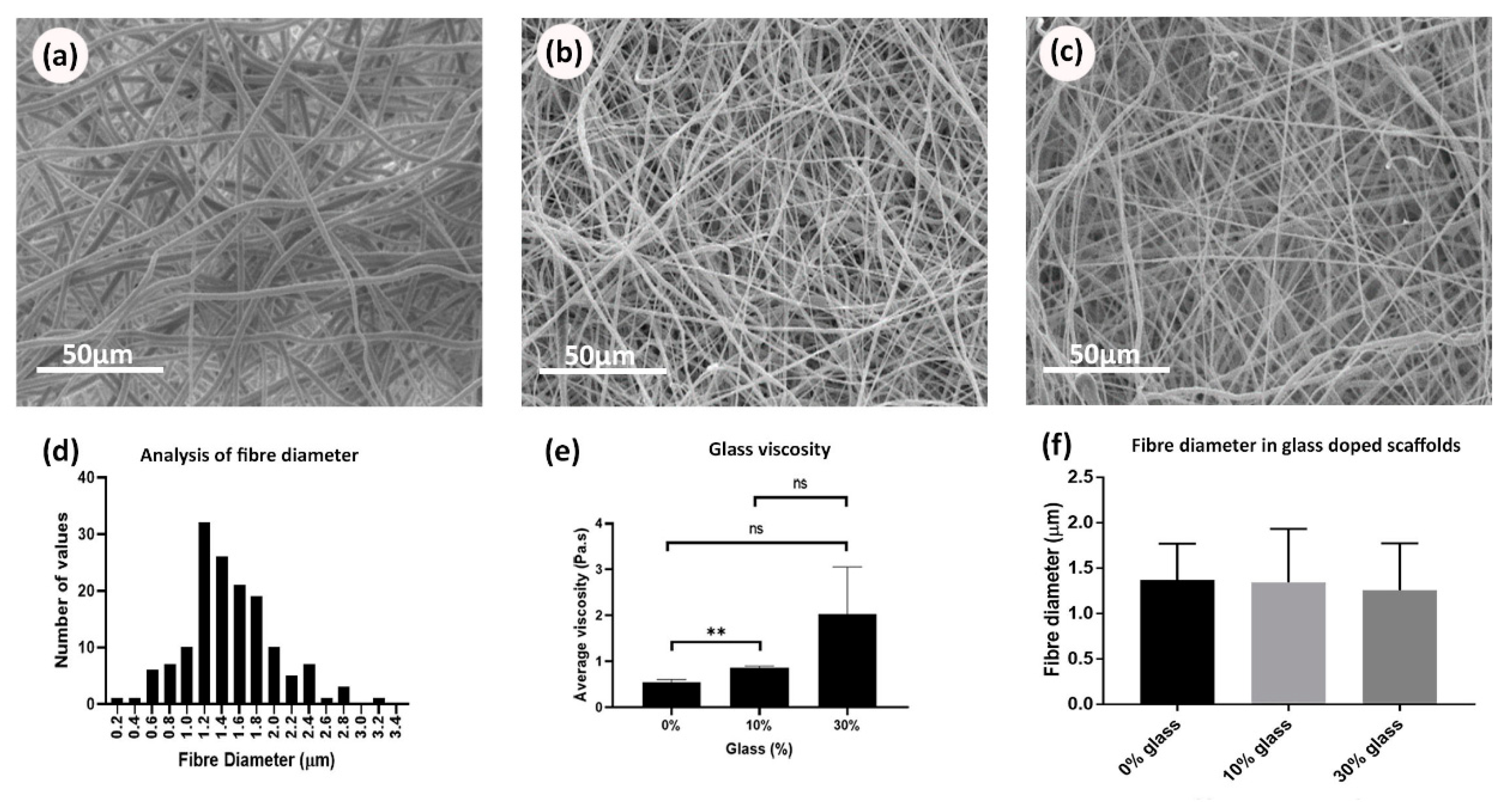
Rheology tests were repeated three times for each composition under the same conditions and the viscosity values at a specific shear rate (2 s−1) were selected for analysis. The mean and standard deviation values were calculated for each of the solution readings, and then the average viscosity values were plotted against different BG compositions of PCL/BG solution as presented in Figure 5e. The inclusion of BG particles at different proportions significantly increased (p = 0.0484) the solution viscosity (under the same environmental conditions). No significant differences in fiber morphology were observed under SEM (Figure 5a–c) and no significant differences in fiber diameter (p = 0.3747) were found when comparing electrospun membranes manufactured with the different BG concentrations (Figure 5d,f).

3.3. Incorporation of Biomolecules on the PCL Scaffolds

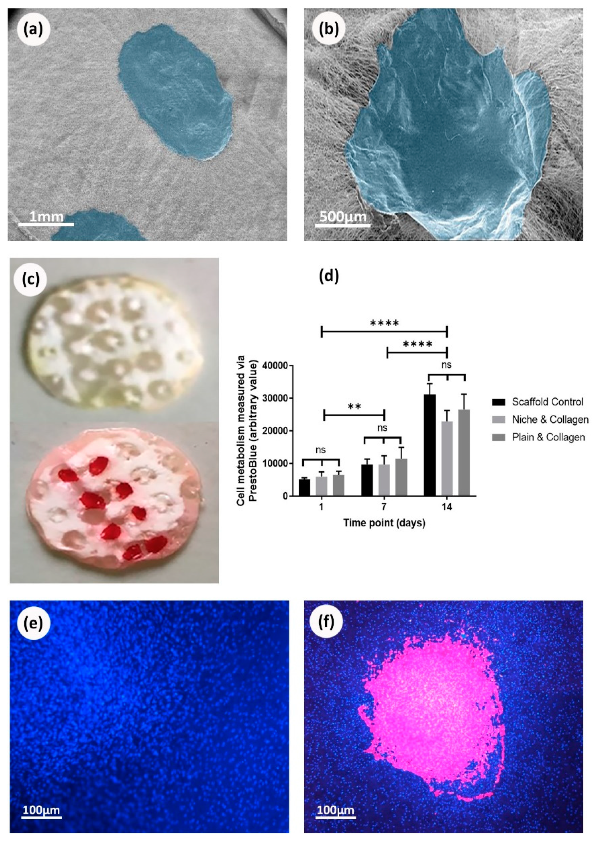
The membranes were successfully coated by collagen and heparin. Figure 6c shows the scaffolds with niches stained positively for collagen (after washing the unbounded stain). The chosen fluorescing heparin can be easily detected throughout the experiment (Figure 7c,d,h). Interestingly, collagen and heparin demonstrated different interaction with the scaffold material. When collagen was added inside the niche, it completely covered the niche and formed a patch like structure (Figure 6b), unlike the heparin which only covered the individual fibers and the niche was still identifiable (Figure 7b).

3.4. Cells Viability on Biofunctionalized PCL Scaffolds

Deposition of collagen on electrospun scaffolds was corroborated using SEM and Sirius red staining (Figure 6a–c). On the other hand, deposition of heparin was demonstrated using SEM and toluidine blue staining (Figure 7a,b,e) as well as fluorescence microscopy (Figure 7c,d). PrestoBlue® assays showed that rMSCs were metabolic active and able to proliferate when cultured on all the studied scaffolds (Figure 6d,f). Overall, the presence or absence of biomolecules (collagen or heparin), as well as the presence or absence of the synthetic niches, did not show any evidence of stimulating or suppressing cells metabolic activity. When observing cell adhesion on different substrates, electrospun scaffolds that were not treated with collagen or heparin displayed a lower number of cells attached but with similar metabolic activity. On heparin and collagen treated samples, cells seemed to adhere and spread better along the fibers which resulted in higher cell density areas for the protein-treated samples (when compared to non-treated PCL samples) (Figure 6e,f).

3.5. Cells Viability on Bioglass Doped Scaffolds

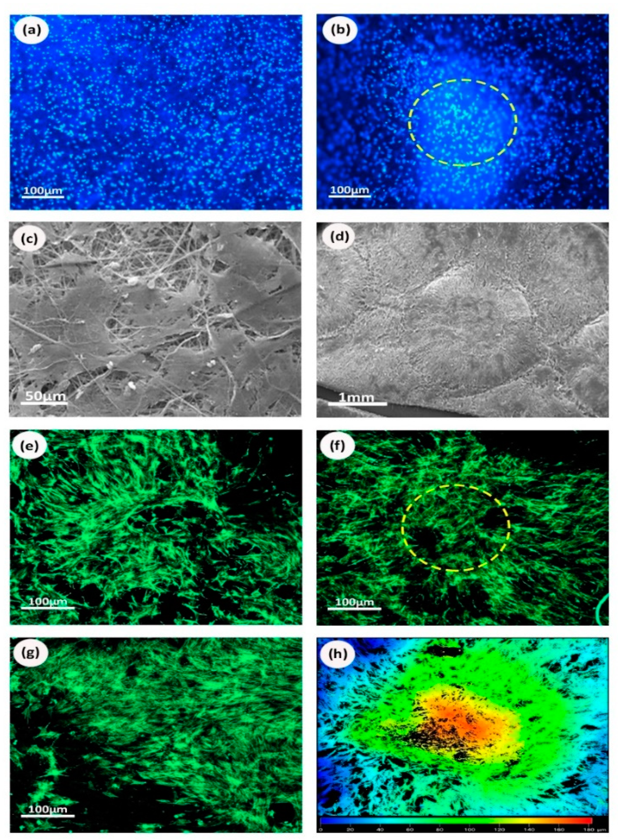
Results confirmed that plain and microfabricated samples doped with BG showed no differences in metabolic activity from days 1–14 (Figure 9h). Similar to the protein coated scaffolds, statistical analysis showed that no design or composition was significantly different than the others. The images obtained by fluorescence, scanning, and confocal microscopies showed cells attached to the matrices with and without niches for all the studied BG concentrations (Figure 8a–g). Plain samples showed that cells were uniformly distributed across the sample surfaces indicating a comparable cell-substrate interaction for all the compositions. The niche structure seemed to favor deeper cell infiltration (up to 180 µm as highlighted in the heat map shown in Figure 8h) and cells followed the alignment of fibers at the wall of the niche.

3.6. Osteogenic Properties of Bioactive Glass

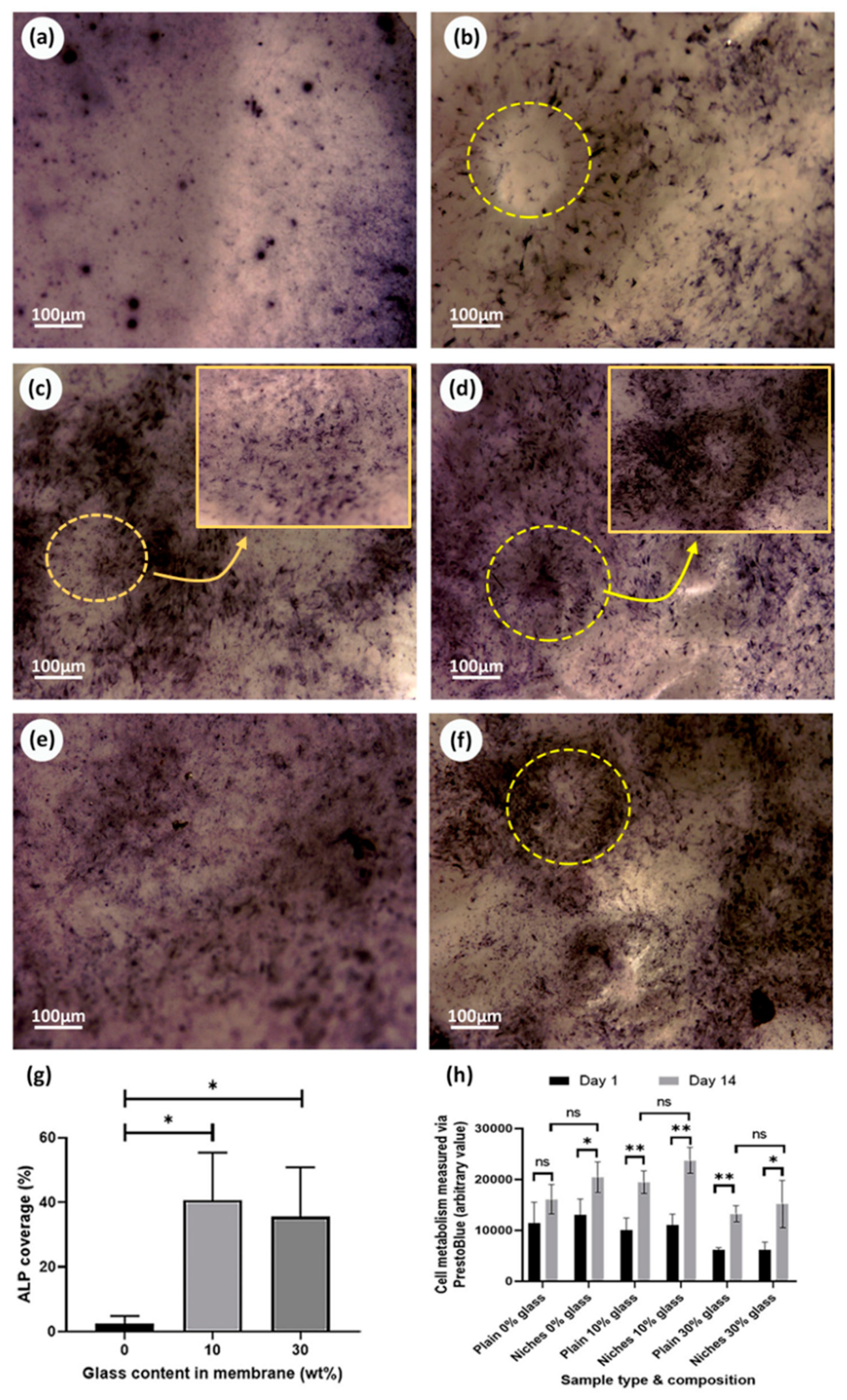
The results from the differential ALP studies are presented in Figure 9. Optical microscopy images allowed us to easily compare the osteogenic behavior of rMSCs seeded on scaffolds with different PCL/BG compositions. As expected, no osteogenic activity was noticed on the cell-free samples. Similarly, cells seeded on scaffolds containing 0% BG exhibited lower osteogenic activity for both niche and plain scaffolds (Figure 9a,b). Higher levels of ALP were produced by cells seeded on samples incorporating 10% and 30% BG (Figure 9c–f) and for samples incorporating niche-like structures (Figure 9g). Plain samples showed a patchy distribution for the ALP stained areas (Figure 9a,c,e). Interestingly, for the niche samples, ALP activity was more noticeable towards the walls of the niche (where the fibers are aligned; see Figure 9d for a high magnification view) rather than towards the center of the niches (with randomly distributed fibers) (Figure 9d,f).

4. Discussion

The scientific community has recently shown a growing interest in mimicking the physiological environment in which adult stem cells naturally reside, since this environment has been reported to have a direct effect in controlling cell behavior and fate [13,19]. Electrospinning strategies have been broadly used for the production of fibrous matrices that can mimic, to an extent, the natural structure of the extracellular matrix [42,43,44]. The versatility of the electrospinning technique enables the incorporation of intricate hierarchical features within the electrospun membranes, for example, by introducing additive manufacturing techniques within the fabrication process [45]. Previous work developed by our group reported the ability of creating complex electrospun microenvironments using different combinations of fabrication techniques, which included selective laser melting [15], extrusion or robocasting [46], stereolithography [22], and 2 photon polymerization [21]; however, these studies have primarily focused on enhancing scaffold physical features and on optimizing the artificial niche morphology and the construct design. This work reports a step further in the area of stem cell niche biofabrication by presenting a palette of biofunctionalization approaches that intend to add an extra degree of hierarchy to our models. As previously described, the niche entity comprises both physical and chemical cues. The models we present here target both of these key aspects. In essence, the complex design of our previously developed microstructured membranes has now been improved via the incorporation of biofunctional additives with the final aim of developing more physiologically relevant artificial stem cell microenvironments for bone tissue engineering.
The development of “synthetic stem cell niches” is a possibility yet to be fully explored in bone regeneration research. For mimicking the physiological stem cell niche, it is necessary to have a wide understanding of its structure and composition. The development of topographically controlled bone regeneration platforms is challenging since the bone structure is not easy to recapitulate. On the one hand, there is not a single “bone stem cell niche as such” but a combination of physical [47] and chemical [48] factors that can drive cells towards an osteogenic pathway.
Although topographically-controlled electrospun membranes have demonstrated to be good models for studying cell behavior, they have sometimes shown to be a simplistic approach for studying bone healing. Therefore, this work aimed to demonstrate the versatility and functionalization potential offered by topographically modified electrospun arrays via the use of relevant proteins and ceramic materials. For this purpose, we selected key components of the stem cell niche (collagen, GAGs, and inorganic components).
GAGs of the heparin/heparan sulphate (HS) class and key components of ECM are of particular interest for their roles during bone remodeling, particularly their ability to bind, stabilize, and protect growth factors from degradation. GAG structural variation seems to be tissue-dependent and, as previously reported, heparin/HS can selectively interact with BMP-2, increasing its tissue availability in the local area and enhancing bone healing [49]. Other studies have described how GAGs stimulate the osteogenic differentiation by upregulating the expression of osteogenic genes [50] and how different sulfation patterns and length can influence heparin selectivity to BMP-2. Collagen is another ECM component majorly present in bone tissue in the form of collagen type I. At nanoscopic level, bone tissue is composed of triple helical collagen molecules that group into collagen fibrils. HA crystals are embedded between collagen gaps increasing structure rigidity [51]. Collagen acts as a template for mineralization initiation and propagation [52]. BG has been confirmed to stimulate enzyme activity [53], vascularization [54], osteoblast adhesion, and differentiation. It can also stimulate mesenchymal cell differentiation into osteoblasts [55]. A significant finding reported by Xynos et al. is that 45S5 BG is able to increase the expression of genes that govern osteogenesis and growth factor production [56].
In this study, our microfabricated patterns were developed using electrospinning, which is broadly used in tissue engineering for developing fibrous mats. Although electrospinning is versatile and generally a robust technique, the inclusion of ceramic materials within manufacturing can result challenging due to changes in viscosity. The polymeric solution viscosity depends on the polymer concentration and the presence and proportion of additives which in turn can affect fiber diameter and morphology during manufacturing. Hence, a rotational shear rheology study was performed to identify the effect of glass particles incorporation on the solution’s viscosity. Our results and statistical analysis confirmed these observations showing significantly higher viscosity for solutions with 30% BG compared to BG-free samples (Figure 5d). Similar results were reported by Fujihara et al., with PCL/CaCO3 composite nanofibres [57] and Kouhi et al., with PCL/nBG composite nanofibers [58]. In addition, it has been speculated that higher concentrations of BG will increase the charge density on the electrospinning jet surface leading to higher electrostatic force and smaller fiber diameter [59]. In our case, an increased solution viscosity in combination with higher charge density might explain why there were no significant changes in fiber diameter for different BG concentrations.
All of the proposed samples were seeded with rMSCs and tested for their biocompatibility using a PrestoBlue® assay to evaluate the cellular metabolic activity. Cells proliferated on both collagen and heparin-treated scaffolds, as well as TCP, at the same rate, using the same conditions with no significant differences. Although PrestoBlue® tests showed no difference in the cellular activity between the scaffolds with and without proteins, the fluorescent images showed a greater number of cells when the scaffolds were functionalized with proteins. We hypothesized that this could have been due to the differentiation of cells to osteoblasts (normally between day 7 and 14), where cells show low metabolic activity as reported by Huang et al. [60]. Further experiments would need to be developed to corroborate this hypothesis.
We also identified that the density of the cell distribution was directly related to the position of the protein (Figure 6f and Figure 7h). rMSCs implied clustering and migration in the range of the protein drop; meanwhile, almost no cellular clusters appeared in the area between the drops. Shi et al. detected similar observations for NIH3T3 cells by incorporating fibronectin gradients into electrospun mats. Further, the study reported a difference in the cellular morphology in relation with the protein concentration [61]. The fluorescent images confirmed the presence of cells inside the niche area and at its edge. We further investigated this by confocal microscopy and we found out that cells were not only growing on the surface, but also penetrated deeply in the inner layers of the scaffolds and particularly inside the niche area. Our current data suggests that the higher surface area offered by the micropocket might have a positive effect on encouraging cell growth, however, further quantification of cell densities inside and outside the microstructures would be needed to elucidate this claim.
It has been stated that high levels of Na2O (BG dissolution product) can elevate the local pH value and inhibit cell growth [62]. Therefore, this study investigated the cytotoxic potential of PCL/BG ratios as high as 30 wt.%. Results suggest that none of the tested compositions had a detrimental effect on cell metabolic activity. After 14 days of culturing, all seeded samples showed comparable metabolic activity to the TCP controls, indicating that all PCL/BG compositions supported normal cell growth. Therefore, there was no significant difference between the proposed designs. This could be attributed to the high compatibility of PCL and the uniform distribution of the BG particles within the electrospun material. Coincident findings were reported by Fabbri et al. for PCL/BG scaffolds fabricated by solid liquid phase separation [63].
ALP assay was performed to estimate the potential osteoblastic differentiation of rMSCs on BG-treated membranes; BG had been reported to have an osteogenic effect on rMSCs, compared to pure PCL mats [59,64]. Our study suggested that both the intricate design and BG concentration influenced the rMSCs osteogenic activity and we reported that niche samples with 30% BG showed an increased level of ALP production around the wall niche area (with higher fiber alignment), unlike the plain samples of the same composition (see high magnification images in Figure 9c,d).
This study considers the role of the scaffold design and bio-active molecules in assisting stem cells differentiation into osteoblasts, which is a key factor in the field of bone tissue engineering. We have successfully employed electrospinning and physical adsorption strategies to immobilize the bioactive molecules on the surface of PCL nanofibers. However, physical surface adsorption depends on electrostatic and intermolecular interactions, which are not particularly strong and might not be sufficient for ensuring long term stabilization [65]. Meanwhile, for the development of bone tissue engineering models, chemical immobilization might offer a more stable covalent attachment to the nanofiber [66]. Our group is currently exploring strategies for comparing our current findings to biofunctional agents immobilized using chemical crosslinking to the PCL nanofibers, for example, via the use of 1-ethyl-3-(3-dimethylaminopropyl) carbodiimide (EDC) and N-hydroxysuccimide (NHS) and via the use of click chemistry approaches to help to inhibit PCL degradation and increase model stability.
Our novel fibrous scaffolds open the door for the development of new and physiologically relevant micro-fabricated membranes that can be used for studying stem cell behavior, as well as for the fabrication of future medical devices for bone tissue repair.

5. Conclusions

The aim of this research was to fabricate a multi-functional micro-fabricated scaffold using key mechano-biological components found in the native bone microenvironment. The presented research also aimed to evaluate the potential of this scaffold to be used as bone tissue engineering model and, ultimately, the basis for a therapeutic device. Our results demonstrated the feasibility of manufacturing electrospun platforms that combined topographical features and biofunctionalization cues. Cell responses to these innovative membranes were also analyzed using relevant primary MSCs. In vitro studies showed that all the materials were biocompatible, emphasizing the protective function of the niche environment (particularly in the presence of biofunctiontal agents), supporting normal cell expansion, migration, and differentiation. It was concluded that stem cell niche biofabrication offers a new strategy for enhancing scaffold functionality in new tissue engineering models and devices.

Author Contributions

Conceptualization, P.V.H. and I.O.A.; methodology, T.E.P., M.E.S.R., D.A., B.J.C.M., G.M.A., and I.O.A.; software, T.E.P.; validation, T.E.P., M.E.S.R., and I.O.; formal analysis, D.A., G.M.A., B.J.C.M., and T.E.P.; investigation, T.E.P. and I.O.A.; resources, P.V.H. and I.O.A.; data curation, D.A., G.M.A., and T.E.P.; writing—original draft preparation, D.A., T.E.P., G.M.A., and I.O.A.; writing—review and editing, B.J.C.M., T.E.P., P.V.H. and I.O.A.; visualization, T.E.P. and I.O.A.; supervision, T.E.P., M.E.S.R., P.V.H., and I.O.A.; project administration, I.O.A.; funding acquisition, P.V.H. All authors have read and agreed to the published version of the manuscript.

Funding

This research was funded by the UK Engineering and Physical Sciences Research Council (EPSRC) (Title: EPSRC Centre for Innovative Manufacturing in Medical Devices (MeDe Innovation) and Grant Number: EP/K029592/1).

Acknowledgments

The authors acknowledge The School of Clinical Dentistry CORE Facilities Team at The University of Sheffield for continuous support and the use of manufacturing and tissue engineering facilities.

Conflicts of Interest

The authors declare no conflict of interest.

References

  1. Storheim, K.; Zwart, J.A. Musculoskeletal disorders and the Global Burden of Disease study. Ann. Rheum Dis. 2014, 73, 949–950. [Google Scholar] [CrossRef] [PubMed] [Green Version]
  2. Hernlund, E.; Svedbom, A.; Ivergard, M.; Compston, J.; Cooper, C.; Stenmark, J.; McCloskey, E.V.; Jonsson, B.; Kanis, J.A. Osteoporosis in the European Union: Medical management, epidemiology and economic burden. A report prepared in collaboration with the International Osteoporosis Foundation (IOF) and the European Federation of Pharmaceutical Industry Associations (EFPIA). Arch. Osteoporos. 2013, 8, 136. [Google Scholar] [CrossRef] [PubMed] [Green Version]
  3. Gautschi, O.P.; Frey, S.P.; Zellweger, R. Bone morphogenetic proteins in clinical applications. ANZ J. Surg. 2007, 77, 626–631. [Google Scholar] [CrossRef] [PubMed]
  4. Polo-Corrales, L.; Latorre-Esteves, M.; Ramirez-Vick, J.E. Scaffold Design for Bone Regeneration. J. Nanosci. Nanotech. 2014, 14, 15–56. [Google Scholar] [CrossRef] [Green Version]
  5. Rahaman, M.N.; Day, D.E.; Bal, B.S.; Fu, Q.; Jung, S.B.; Bonewald, L.F.; Tomsia, A.P. Bioactive glass in tissue engineering. Acta Biomater. 2011, 7, 2355–2373. [Google Scholar] [CrossRef] [Green Version]
  6. Schofield, R. The relationship between the spleen colony-forming cell and the haemopoietic stem cell. Blood Cells 1978, 4, 7–25. [Google Scholar]
  7. Cotsarelis, G.; Sun, T.T.; Lavker, R.M. Label-retaining cells reside in the bulge area of pilosebaceous unit: Implications for follicular stem cells, hair cycle, and skin carcinogenesis. Cell 1990, 61, 1329–1337. [Google Scholar] [CrossRef]
  8. Potten, C.S.; Owen, G.; Booth, D. Intestinal stem cells protect their genome by selective segregation of template DNA strands. J. Cell Sci. 2002, 115, 2381–2388. [Google Scholar]
  9. Cotsarelis, G.; Cheng, S.Z.; Dong, G.; Sun, T.T.; Lavker, R.M. Existence of Slow-Cycling Limbal Epithelial Basal Cells That Can Be Preferentially Stimulated to Proliferate - Implications on Epithelial Stem-Cells. Cell 1989, 57, 201–209. [Google Scholar] [CrossRef]
  10. Schermer, A.; Galvin, S.; Sun, T.T. Differentiation-related expression of a major 64K corneal keratin in vivo and in culture suggests limbal location of corneal epithelial stem cells. J. Cell Biol. 1986, 103, 49–62. [Google Scholar] [CrossRef]
  11. Gage, F.H.; Kempermann, G.; Palmer, T.D.; Peterson, D.A.; Ray, J. Multipotent progenitor cells in the adult dentate gyrus. J. Neurobiol. 1998, 36, 249–266. [Google Scholar] [CrossRef]
  12. Loeffler, M.; Roeder, I. Tissue stem cells: Definition, plasticity, heterogeneity, self-organization and models—A conceptual approach. Cells Tissues Organs. 2002, 171, 8–26. [Google Scholar] [CrossRef] [PubMed]
  13. Lutolf, M.P.; Blau, H.M. Artificial Stem Cell Niches. Adv. Mater. 2009, 21, 3255–3268. [Google Scholar] [CrossRef] [PubMed] [Green Version]
  14. Roeder, I.; Loeffler, M.; Glauche, I.; Participants, O. Towards a quantitative understanding of stem cell-niche interaction: Experiments, models, and technologies. Blood Cell Mol. Dis. 2011, 46, 308–317. [Google Scholar] [CrossRef]
  15. Paterson, T.E.; Beal, S.N.; Santocildes-Romero, M.E.; Sidambe, A.T.; Hatton, P.V.; Asencio, I.O. Selective laser melting-enabled electrospinning: Introducing complexity within electrospun membranes. Proc. Inst. Mech. Eng. Part H 2017, 231, 565–574. [Google Scholar] [CrossRef] [Green Version]
  16. Raimondi, M.T.; Eaton, S.M.; Lagana, M.; Aprile, V.; Nava, M.M.; Cerullo, G.; Osellame, R. Three-dimensional structural niches engineered via two-photon laser polymerization promote stem cell homing. Acta Biomater. 2013, 9, 4579–4584. [Google Scholar] [CrossRef]
  17. Kaukua, N.; Shahidi, M.K.; Konstantinidou, C.; Dyachuk, V.; Kaucka, M.; Furlan, A.; An, Z.W.; Wang, L.L.; Hultman, I.; Ahrlund-Richter, L.; et al. Glial origin of mesenchymal stem cells in a tooth model system. Nature 2014, 513. [Google Scholar] [CrossRef] [Green Version]
  18. Gill, A.A.; Ortega, I.; Kelly, S.; Claeyssens, F. Towards the fabrication of artificial 3D microdevices for neural cell networks. Biomed. Microdevices 2015, 17. [Google Scholar] [CrossRef]
  19. Ortega, I.; Deshpande, P.; Gill, A.A.; MacNeil, S.; Claeyssens, F. Development of a microfabricated artificial limbus with micropockets for cell delivery to the cornea. Biofabrication 2013, 5. [Google Scholar] [CrossRef] [Green Version]
  20. Ortega, I.; McKean, R.; Ryan, A.J.; MacNeil, S.; Claeyssens, F. Characterisation and evaluation of the impact of microfabricated pockets on the performance of limbal epithelial stem cells in biodegradable PLGA membranes for corneal regeneration. Biomater. Sci. UK 2014, 2, 723–734. [Google Scholar] [CrossRef] [Green Version]
  21. Ortega, I.; Ryan, A.J.; Deshpande, P.; MacNeil, S.; Claeyssens, F. Combined microfabrication and electrospinning to produce 3-D architectures for corneal repair. Acta Biomater. 2013, 9, 5511–5520. [Google Scholar] [CrossRef] [PubMed]
  22. Ortega, I.; Sefat, F.; Deshpande, P.; Paterson, T.; Ramachandran, C.; Ryan, A.J.; MacNeil, S.; Claeyssens, F. Combination of Microstereolithography and Electrospinning to Produce Membranes Equipped with Niches for Corneal Regeneration. JOVE J. Vis. Exp. 2014. [Google Scholar] [CrossRef] [Green Version]
  23. Fisher, O.Z.; Khademhosseini, A.; Langer, R.; Peppas, N.A. Bioinspired Materials for Controlling Stem Cell Fate. Acc. Chem. Res. 2010, 43, 419–428. [Google Scholar] [CrossRef] [PubMed] [Green Version]
  24. Moeller, H.C.; Mian, M.K.; Shrivastava, S.; Chung, B.G.; Khademhosseini, A. A microwell array system for stem cell culture. Biomaterials 2008, 29, 752–763. [Google Scholar] [CrossRef] [Green Version]
  25. Muller, E.; Grinenko, T.; Pompe, T.; Waskow, C.; Werner, C. Space constraints govern fate of hematopoietic stem and progenitor cells in vitro. Biomaterials 2015, 53, 709–715. [Google Scholar] [CrossRef] [PubMed] [Green Version]
  26. Yin, T.; Li, L.H. The stem cell niches in bone. J. Clin. Investig. 2006, 116, 1195–1201. [Google Scholar] [CrossRef] [PubMed]
  27. Minardi, S.; Corradetti, B.; Taraballi, F.; Sandri, M.; Van Eps, J.; Cabrera, F.J.; Weiner, B.K.; Tampieri, A.; Tasciotti, E. Evaluation of the osteoinductive potential of a bio-inspired scaffold mimicking the osteogenic niche for bone augmentation. Biomaterials 2015, 62, 128–137. [Google Scholar] [CrossRef] [Green Version]
  28. Danti, S.; Serino, L.P.; D′Alessandro, D.; Moscato, S.; Danti, S.; Trombi, L.; Dinucci, D.; Chiellini, F.; Pietrabissa, A.; Lisanti, M.; et al. Growing bone tissue-engineered niches with graded osteogenicity: An in vitro method for biomimetic construct assembly. Tissue Eng. Part C 2013, 19, 911–924. [Google Scholar] [CrossRef] [Green Version]
  29. Muerza-Cascante, M.L.; Shokoohmand, A.; Khosrotehrani, K.; Haylock, D.; Dalton, P.D.; Hutmacher, D.W.; Loessner, D. Endosteal-like extracellular matrix expression on melt electrospun written scaffolds. Acta Biomater. 2017, 52, 145–158. [Google Scholar] [CrossRef] [Green Version]
  30. Tang, W.; Lin, D.; Yu, Y.; Niu, H.; Guo, H.; Yuan, Y.; Liu, C. Bioinspired trimodal macro/micro/nano-porous scaffolds loading rhBMP-2 for complete regeneration of critical size bone defect. Acta Biomater. 2016, 32, 309–323. [Google Scholar] [CrossRef]
  31. Di Maggio, N.; Piccinini, E.; Jaworski, M.; Trumpp, A.; Wendt, D.J.; Martin, I. Toward modeling the bone marrow niche using scaffold-based 3D culture systems. Biomaterials 2011, 32, 321–329. [Google Scholar] [CrossRef] [PubMed]
  32. Kular, J.K.; Basu, S.; Sharma, R.I. The extracellular matrix: Structure, composition, age-related differences, tools for analysis and applications for tissue engineering. J. Tissue Eng. 2014, 5. [Google Scholar] [CrossRef] [PubMed]
  33. Capila, I.; Linhardt, R.J. Heparin-protein interactions. Angew. Chem. Int. Ed. Engl. 2002, 41, 391–412. [Google Scholar] [CrossRef]
  34. Farbod, K.; Nejadnik, M.R.; Jansen, J.A.; Leeuwenburgh, S.C.G. Interactions Between Inorganic and Organic Phases in Bone Tissue as a Source of Inspiration for Design of Novel Nanocomposites. Tissue Eng. Part B 2014, 20, 173–188. [Google Scholar] [CrossRef] [Green Version]
  35. Chuenjitkuntaworn, B.; Osathanon, T.; Nowwarote, N.; Supaphol, P.; Pavasant, P. The efficacy of polycaprolactone/hydroxyapatite scaffold in combination with mesenchymal stem cells for bone tissue engineering. J. Biomed. Mater. Res. A 2016, 104, 264–271. [Google Scholar] [CrossRef]
  36. Ning, L.; Malmstrom, H.; Ren, Y.F. Porous collagen-hydroxyapatite scaffolds with mesenchymal stem cells for bone regeneration. J. Oral. Implantol. 2015, 41, 45–49. [Google Scholar] [CrossRef] [PubMed]
  37. Sanaei-Rad, P.; Jafarzadeh Kashi, T.S.; Seyedjafari, E.; Soleimani, M. Enhancement of stem cell differentiation to osteogenic lineage on hydroxyapatite-coated hybrid PLGA/gelatin nanofiber scaffolds. Biologicals 2016, 44, 511–516. [Google Scholar] [CrossRef]
  38. Fiume, E.; Barberi, J.; Verne, E.; Baino, F. Bioactive Glasses: From Parent 45S5 Composition to Scaffold-Assisted Tissue-Healing Therapies. J. Funct. Biomater. 2018, 9, 24. [Google Scholar] [CrossRef] [Green Version]
  39. Fu, Q.; Saiz, E.; Rahaman, M.N.; Tomsia, A.P. Bioactive glass scaffolds for bone tissue engineering: State of the art and future perspectives. Mat. Sci. Eng. C Mater. 2011, 31, 1245–1256. [Google Scholar] [CrossRef] [PubMed] [Green Version]
  40. Mezger, T. The Rheology Handbook; Vincentz Network: Hnaover, Germany, 2011. [Google Scholar]
  41. Santocildes-Romero, M.E.; Crawford, A.; Hatton, P.V.; Goodchild, R.L.; Reaney, I.M.; Miller, C.A. The osteogenic response of mesenchymal stromal cells to strontium-substituted bioactive glasses. J. Tissue Eng. Regen. M 2015, 9, 619–631. [Google Scholar] [CrossRef]
  42. Zafar, M.; Najeeb, S.; Khurshid, Z.; Vazirzadeh, M.; Zohaib, S.; Najeeb, B.; Sefat, F. Potential of Electrospun Nanofibers for Biomedical and Dental Applications. Materials 2016, 9, 73. [Google Scholar] [CrossRef]
  43. Li, X.M.; Wang, L.; Fan, Y.B.; Feng, Q.L.; Cui, F.Z.; Watari, F. Nanostructured scaffolds for bone tissue engineering. J. Biomed. Mater. Res. Part A 2013, 101, 2424–2435. [Google Scholar] [CrossRef] [PubMed]
  44. Liu, H.F.; Ding, X.L.; Zhou, G.; Li, P.; Wei, X.; Fan, Y.B. Electrospinning of Nanofibers for Tissue Engineering Applications. J. Nanomater. 2013. [Google Scholar] [CrossRef] [Green Version]
  45. Schutte, J.; Yuan, X.W.; Dirven, S.; Potgieter, J. The opportunity of Electrospinning as a form of Additive Manufacturing in Biotechnology. I C Mech. Mach. Vis. Pr. 2017, 131–136. [Google Scholar] [CrossRef]
  46. Ortega, I.; Dew, L.; Kelly, A.G.; Chong, C.K.; MacNeil, S.; Claeyssens, F. Fabrication of biodegradable synthetic perfusable vascular networks via a combination of electrospinning and robocasting. Biomater. Sci. UK 2015, 3, 592–596. [Google Scholar] [CrossRef]
  47. Discher, D.E.; Mooney, D.J.; Zandstra, P.W. Growth factors, matrices, and forces combine and control stem cells. Science 2009, 324, 1673–1677. [Google Scholar] [CrossRef] [Green Version]
  48. Huang, Z.; Ren, P.G.; Ma, T.; Smith, R.L.; Goodman, S.B. Modulating osteogenesis of mesenchymal stem cells by modifying growth factor availability. Cytokine 2010, 51, 305–310. [Google Scholar] [CrossRef]
  49. Murali, S.; Rai, B.; Dombrowski, C.; Lee, J.L.; Lim, Z.X.; Bramono, D.S.; Ling, L.; Bell, T.; Hinkley, S.; Nathan, S.S.; et al. Affinity-selected heparan sulfate for bone repair. Biomaterials 2013, 34, 5594–5605. [Google Scholar] [CrossRef]
  50. Mathews, S.; Mathew, S.A.; Gupta, P.K.; Bhonde, R.; Totey, S. Glycosaminoglycans enhance osteoblast differentiation of bone marrow derived human mesenchymal stem cells. J. Tissue Eng. Regen. Med. 2014, 8, 143–152. [Google Scholar] [CrossRef]
  51. Gong, T.; Xie, J.; Liao, J.; Zhang, T.; Lin, S.; Lin, Y. Nanomaterials and bone regeneration. Bone Res. 2015, 3, 15029. [Google Scholar] [CrossRef]
  52. Ferreira, A.M.; Gentile, P.; Chiono, V.; Ciardelli, G. Collagen for bone tissue regeneration. Acta Biomater. 2012, 8, 3191–3200. [Google Scholar] [CrossRef]
  53. Lobel, K.D.; Hench, L.L. In vitro adsorption and activity of enzymes on reaction layers of bioactive glass substrates. J. Biomed. Mater. Res. 1998, 39, 575–579. [Google Scholar] [CrossRef]
  54. Keshaw, H.; Forbes, A.; Day, R.M. Release of angiogenic growth factors from cells encapsulated in alginate beads with bioactive glass. Biomaterials 2005, 26, 4171–4179. [Google Scholar] [CrossRef] [PubMed]
  55. Lu, H.H.; Tang, A.; Oh, S.C.; Spalazzi, J.P.; Dionisio, K. Compositional effects on the formation of a calcium phosphate layer and the response of osteoblast-like cells on polymer-bioactive glass composites. Biomaterials 2005, 26, 6323–6334. [Google Scholar] [CrossRef]
  56. Xynos, I.D.; Edgar, A.J.; Buttery, L.D.K.; Hench, L.L.; Polak, J.M. Ionic products of bioactive glass dissolution increase proliferation of human osteoblasts and induce insulin-like growth factor II mRNA expression and protein synthesis. Biochem. Res. 2000, 276, 461–465. [Google Scholar] [CrossRef] [PubMed]
  57. Fujihara, K.; Kotaki, M.; Ramakrishna, S. Guided bone regeneration membrane made of polycaprolactone/calcium carbonate composite nano-fibers. Biomaterials 2005, 26, 4139–4147. [Google Scholar] [CrossRef] [PubMed]
  58. Kouhi, M.; Morshed, M.; Varshosaz, J.; Fathi, M.H. Poly (epsilon-caprolactone) incorporated bioactive glass nanoparticles and simvastatin nanocomposite nanofibers: Preparation, characterization and in vitro drug release for bone regeneration applications. Chem. Eng. J. 2013, 228, 1057–1065. [Google Scholar] [CrossRef]
  59. Lin, H.M.; Lin, Y.H.; Hsu, F.Y. Preparation and characterization of mesoporous bioactive glass/polycaprolactone nanofibrous matrix for bone tissues engineering. J. Mater. Sci. Mater. M 2012, 23, 2619–2630. [Google Scholar] [CrossRef] [PubMed]
  60. Huang, Z.; Nelson, E.R.; Smith, R.L.; Goodman, S.B. The sequential expression profiles of growth factors from osteoprogenitors [correction of osteroprogenitors] to osteoblasts in vitro. Tissue Eng. 2007, 13, 2311–2320. [Google Scholar] [CrossRef]
  61. Shi, J.; Wang, L.; Zhang, F.; Li, H.; Lei, L.; Liu, L.; Chen, Y. Incorporating Protein Gradient into Electrospun Nanofibers As Scaffolds for Tissue Engineering. ACS Appl. Mater. Inter. 2010, 2, 1025–1030. [Google Scholar] [CrossRef]
  62. Wallace, K.E.; Hill, R.G.; Pembroke, J.T.; Brown, C.J.; Hatton, P.V. Influence of sodium oxide content on bioactive glass properties. J. Mater. Sci. Mater. Med. 1999, 10, 697–701. [Google Scholar] [CrossRef] [PubMed]
  63. Fabbri, P.; Cannillo, V.; Sola, A.; Dorigato, A.; Chiellini, F. Highly porous polycaprolactone-45S5 Bioglass (R) scaffolds for bone tissue engineering. Compos. Sci. Technol. 2010, 70, 1869–1878. [Google Scholar] [CrossRef] [Green Version]
  64. Kaufmann, E.A.B.E.; Ducheyne, P.; Shapiro, I.M. Evaluation of osteoblast response to porous bioactive glass (45S5) substrates by RT-PCR analysis. Tissue Eng. 2000, 6, 19–28. [Google Scholar] [CrossRef]
  65. Yoshida, M.; Langer, R.; Lendlein, A.; Lahann, J. From advanced biomedical coatings to multi-functionalized biomaterials. Polym. Rev. 2006, 46, 347–375. [Google Scholar] [CrossRef]
  66. Yoo, H.S.; Kim, T.G.; Park, T.G. Surface-functionalized electrospun nanofibers for tissue engineering and drug delivery. Adv. Drug Deliv. Rev. 2009, 61, 1033–1042. [Google Scholar] [CrossRef]
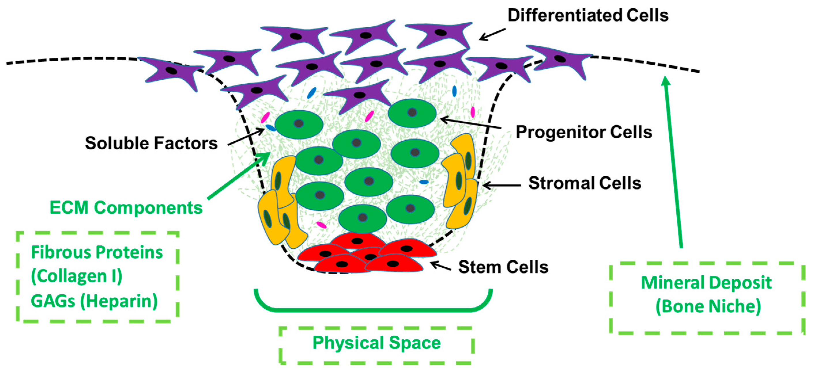
Figure 1. General schematic of a stem cell niche environment showing key characteristics, cell type locations, and highlighting (in green) the specific components we aimed to investigate in this work (manufacture of a physical and discrete space and biofunctionalization with extracellular matrix (ECM) and mineral components (Bioglass, BG)).
Processes 08 01341 g001
Figure 2. Schematic highlighting the manufacturing approach undertaken to develop the topographically controlled electrospun substrates and summary of chosen biofunctionalization strategies to modify the electrospun niche-like membranes.
Processes 08 01341 g002
Figure 3. Scanning electron micrographs of the electrospun scaffolds: (a) Scanning electron microscopy (SEM) of Polycaprolactone (PCL) electrospun mesh, plain sample; (b) SEM of PCL electrospun niche sample showing the complete niche structure with the surrounding plain area between niches; (c) PCL electrospun fibers randomly distributed in a plain scaffold; (d) SEM picture showing the different patterns of fiber distribution within the niche structure; (e) SEM micrographs of BG powder, showing milled BG particles with irregular coarse surfaces and variable particle sizes within the same sample; (f) electrospun plain sample with BG, arrow points at BG particles appear within the structure of the randomly oriented fibers; (g) electrospun niche samples with BG, circle shows the edge of the niche; (h) higher magnification of the electrospun niche samples of PCL with BG, arrow points at BG particles appear within the structure of the aligned fibers.
Processes 08 01341 g003
Figure 4. SEM analysis of electrospun scaffolds fibers and alignment impact on cell morphology: (a) SEM micrograph of synthetic niche in electrospun scaffold; (bd) SEM images showing different sections of fibers within the niche, specifically: (b) Randomly aligned fiber area outside niche; (c) aligned fibers in the niche wall; (d) randomly aligned fiber area at the bottom of the niche; (e) analysis of the fiber alignment within the different sections of the niche presented as a histogram; (f) morphology of rMSCs growing on more random fibers; (g) morphology of rMSCs growing on more aligned fibers.
Processes 08 01341 g004
Figure 5. SEM micrographs of PCL/BG plain samples showing the effect of BG concentration on fiber morphology and diameter measurements: (a) PCL/0% BG; (b) PCL/10% BG; (c) PCL/30% BG; (d) analysis of fiber diameter from electrospun scaffolds by use of a histogram showing size distribution; (e) bar graph showing the effect of the BG concentrations on the average viscosity of the PCL/BG solutions; (f) bar graph showing the effect of BG concentrations on the fiber diameter.
Processes 08 01341 g005
Figure 6. Deposition of collagen onto electrospun scaffolds and 14th day culture with MSCs: (a) SEM image of plain scaffolds with collagen deposited on the surface. Collagen false colored blue using photoshop; (b) SEM image of collagen deposited into niches on electrospun scaffolds. Collagen false colored blue; (c) Sirius red staining of scaffold control and red staining of scaffolds with collagen deposition showing the presence of collagen; (d) cell metabolic data from PrestoBlue® assay based on a 14 day culture of rMSC cells on electrospun scaffolds with and without niches and collagen. No statistical difference is found between any of the conditions, ANOVA; (e) fluorescence image of nuclei DAPI staining (blue) 14 days culture of rMSC cells on plain scaffolds without collagen; (f) fluorescence image of nuclei DAPI staining (blue) from 14 days culture of rMSC cells on plain scaffolds with collagen (false colored pink).
Processes 08 01341 g006
Figure 7. Deposition of heparin onto electrospun scaffolds and 14 day culture with rMSCs: (a) SEM image of plain scaffolds with heparin deposited on the surface; (b) SEM image of heparin deposited into niches; (c) fluorescent image of fluorescent heparin (green) deposited onto electrospun scaffolds without niches; (d) fluorescent image of fluorescent heparin (green) deposited onto electrospun scaffold with niches; (e) toluidine Blue staining for plain heparin coated scaffolds and control; (f) cell metabolic data from PrestoBlue® assay based on a 14 day culture of rMSC cells on electrospun scaffolds with and without niches and heparin. No statistical difference is found between any of the conditions, ANOVA test used, bars are the mean ± SD (N = 1, n = 3); (g) fluorescent image of nuclei DAPI staining (blue) 14 days culture of rMSC cells on plain scaffold without heparin; (h) fluorescent image of nuclei DAPI staining (blue) and fluorescent heparin (green) from 14 days culture of rMSC cells on plain scaffold.
Processes 08 01341 g007
Figure 8. Cell morphology and distribution on scaffolds functionalized with BG: (a) fluorescent microscopy of nuclei DAPI staining (blue) of plain samples with 10% BG; (b) fluorescent microscopy of image of nuclei DAPI staining (blue) of niche samples with 10% BG; (c) SEM micrographs of 30% BG plain samples; (d) SEM micrographs of niche samples with 10% BG; (e) confocal microscopy of niche 10% BG; (f) confocal microscopy of niche bottom 30% BG; (g) Confocal microscopy of plain 10% BG; (h) heat map of confocal imaging microscopy for niche structure, each color indicates a specific depth of cell penetration. Cells appear to penetrate as deep as 180 µm at the center of the niche (red area), while around the niche edge they exhibit superficial expansion (blue area).
Processes 08 01341 g008
Figure 9. Biological evaluation of scaffolds functionalized with BG. ALP assay pictures: (a) plain sample 0% BG; (b) niche sample 0% BG; (c) plain sample 10% BG; (d) Niche sample 10% BG; (e) plain 30% BG; (f) niche sample 30% BG; (g) ALP quantification for niche samples obtained by calculating the percentage of stain coverage in the optical images; (h) cell metabolic data from PrestoBlue® assay based on comparing the effect of membrane design and composition between day 1 and day 14 of the experiment.
Processes 08 01341 g009
Publisher’s Note: MDPI stays neutral with regard to jurisdictional claims in published maps and institutional affiliations.