Article

Techno-Economic Analysis of a Kilo-Watt Scale Hydrogen-Bromine Flow Battery System for Sustainable Energy Storage

by
Yohanes Antonius Hugo
1,2,
Wiebrand Kout
2,
Guido Dalessi
2,
Antoni Forner-Cuenca
1,
Zandrie Borneman
1,3 and
Kitty Nijmeijer
1,3,*
1
Membrane Materials and Processes, Department of Chemical Engineering and Chemistry, Eindhoven University of Technology, P.O. Box 513, 5600 MB Eindhoven, The Netherlands
2
Elestor B.V., P.O. Box 882, 6800 AW Arnhem, The Netherlands
3
Dutch Institute for Fundamental Energy Research (DIFFER), P.O. Box 6336, 5600 HH Eindhoven, The Netherlands
*
Author to whom correspondence should be addressed.
Processes 2020, 8(11), 1492; https://doi.org/10.3390/pr8111492
Submission received: 30 September 2020 / Revised: 2 November 2020 / Accepted: 11 November 2020 / Published: 18 November 2020

Abstract

:
Transitioning to a renewable energy economy requires the widespread integration of solar and wind power, which are intermittent, into the electricity grid. To this goal, it is paramount to develop cost-competitive, reliable, location-independence, and large-scale energy storage technologies. The hydrogen bromine flow battery (HBFB) is a promising technology given the abundant material availability and its high power density. Here, the aim is to perform a comprehensive techno-economic analysis of a 500 kW nominal power/5 MWh HBFB storage system, based on the levelized cost of storage approach. Then, we systematically analyze stack and system components costs for both the current base and a future scenario (2030). We find that, for the base case, HBFB capital investments are competitive to Li-ion battery technology, highlighting the potential of large-scale HBFB market introduction. Improving the stack performance and reducing the stack and system costs are expected to result in ~62% reduction potential in capital investments. The base-case levelized cost of storage, $0.074/kWh, is sufficiently low for a wind-solar storage system to compete with a fossil-based power plant, with potential for reduction to $0.034/kWh in the future scenario. Sensitivity analysis indicates that the levelized cost of storage is most sensitive towards the stack lifetime, which motivates research efforts into advanced electrocatalysts with higher durability and ion-exchange membranes with improved selectivity.

1. Introduction

The European Union (EU) should set targets and implement policies and measures to limit the global average temperature increase to 1.5 °C in line with the Paris Agreement [1]. An agreement was made in 2019 in the European Council on net-zero greenhouse gas (GHG) emissions by 2050 as the target for the EU long-term climate strategy [2]. A Commission proposal, based on the agreed target for 2050 defined a cost-effective intermediate target for 2030 (currently set as at least 40%). The Netherlands proposes the 2030 target to be increased to 55%, to be agreed in 2020 [3]. Furthermore, the Dutch government encourages that both the 2030 and 2050 targets become part of the European Climate Law [3]. A major aspect of the Dutch reflection on the European Green Deal is the strong focus on sustainable energy generation from e.g., wind and solar energy sources combined with a focus on sustainable electrification of the industrial, mobility, and electricity sectors, the built environment, and agriculture. Over the last 10 years, wind and solar electricity generation processes have experienced tremendous cost reductions. The levelized cost of wind and solar is predicted to be as low as $0.03/kWh, which is lower than the most efficient coal-fired power plants [4]. The critical remaining issue is the cost of flexibility that is associated with the intermittent nature of solar and wind energy. At present, grids can only cope with ~24% of the influx of energy from renewables [5]. Electricity storage systems that store surplus electricity and release it when there is high demand are essential to overcome the problem of intermittency.
To enable the transition from a fossil fuel-based to a sustainable energy economy, the wind-solar-storage (WSS) system needs to be cost-competitive with the current energy system. Traditional power plants produce reliable electricity at $0.05/kWh at the expense of large greenhouse gas emissions [6]. According to the literature [7], one-third of the renewables produced have to be stored for a reliable and sustainable energy system. Currently, wind-solar power can be produced realistically at $0.03/kWh. These imply that the levelized costs of storage (LCoS) should remain <$0.06/kWh (see Equation (8)). The LCoS expresses the bottom line costs for storing 1 kWh electricity. This term enables meaningful comparison of different storage technologies and from an economic point of view to determine whether the WSS system is economically feasible.
Currently, there is a strong market pull for low-cost electricity storage systems. In 2017, there were 176 gigawatts (GW) of installed storage power and about 4.67 terawatt-hours (TWh) total storage capacity globally, where 96% of the capacity is dominated by pumped hydropower technology [8]. Pumped hydropower, although reliable and cost-effective, is geographically limited for many countries and requires large capital costs [9].
Due to its versatile nature, electrochemical energy storage is a promising and rapidly growing market. Potentially very attractive and promising in this respect are flow batteries. As opposed to sealed battery technologies, flow batteries have the advantage that power and capacity are decoupled. The power is determined by the area resistance and the active area of the membrane-electrode assembly (MEAs) of the reactor, while the storage capacity depends on the concentration of redox molecules in the electrolyte and tank volume. Moreover, they feature superior durability (i.e., there is no intercalation reaction) and depth of discharge limit and flow batteries have a limited self-discharge rate since the reactants can be replaced from the electrochemical stacks during long-term storage [10].
Among the different flow battery options, the hydrogen-bromine flow battery (HBFB) is one of the most promising ones, with a demonstrated high peak power density (1.4 W/cm2), energy efficiency (90%), and energy utilization (93% at 0.9 A/cm2) [10], which is driven by the facile kinetics of the redox reactions. Moreover, hydrogen and hydrobromic acid are widely available. Over the last years, several groups have investigated HBFB technology from a technological perspective [11,12,13,14].
However, interests and activities from the industries and governments only can be generated by an economic prospect of HBFB technology. Although there are several other techno-economic studies available for flow batteries [15,16], only one techno-economic analysis for HBFB has been performed by Singh and McFarland in 2015 [17]. After that time there have been many developments in the field of flow batteries. This emphasizes the importance of this research into the cost analysis of current and future (2030) HBFB systems.
The goal of the present study is to perform a comprehensive techno-economic analysis of the HBFB technology from an applied perspective, based on extensive collaboration with an industrial HBFB developer and suppliers based on today’s industrial practice. To have access to industrial drivers and the costs of the technology, the work has been carried out in collaboration with industrial suppliers and especially Elestor BV, one of the leading companies in HBFB technology development and production. The findings of this study provide the LCoS of an HBFB system and will serve as the current roadmap to give directions to future academic and industrial research in the area of energy storage using flow batteries. Nevertheless, this techno-economic analysis is still a prediction because the system has yet to be built and operated.
Here, we first describe the principles of the HBFB technology (Section 2) and the model methodology and assumptions (Section 3), with a distinction between the costs of power (i.e., stack) and energy (i.e., electrolyte and peripheral system). Then, the results of the model are discussed in the light of two scenarios: the base scenario where the system would be built today and a future scenario for 2030 assuming that large scale production is feasible (Section 4). Finally, at the end of Section 4, we perform a sensitivity analysis to identify key areas with a larger potential for cost reduction and provide recommendations for researchers and flow battery technology practitioners.

2. Principle of Hydrogen-Bromine Flow Battery (HBFB) Technology

The HBFB (Figure 1) stores electricity by interconverting electrical to chemical energy in the oxidation of Br- (present as HBr solution) into Br2 at the cathode. Br2 subsequently reacts further with Br- to form Br3- until equilibrium conditions are reached [13]. The released protons diffuse through the ion-exchange membrane that electrically-separates the cathode from the anode. At the anode, this H+ is reduced to form H2 gas. The opposite reactions occur when electricity is discharged from the system. The difference in chemical potential between hydrogen and bromine species is the driving force for these electrochemical reactions to take place. The theoretical standard open-circuit voltage per cell at 25 °C is 1.098 V [18]. The corresponding redox reactions are:
C a t h o d e :   2 Br     charge discharge   Br 2 ( aq )   +   2 e             E 0 - =   - 1.098   V   v s .   S H E A n o d e :   2 H +   +   2 e     charge   discharge   H 2             E 0 + =   0   V   vs .   S H E Overall :   2 H B r 2 ( aq )   charge   discharge   H 2   +   B r 2 ( aq )           E 0 , c e l l   =   1.98   V
The equilibrium reaction of Br2 is:
Br 2   ( aq ) + Br -     Br 3 -           K Br 3 - / Br 2 / Br -   =   17
The HBFB cell and its different components are presented in Figure 1 and further discussed in detail in Section 3.4.

3. Methodology and Assumptions

3.1. HBFB Performance Parameters and System Model

3.1.1. Size

Due to the relatively low costs of the electrolyte, there is an advantage to going to long-term storage (i.e., low capital investment per kWh) in contrast to other existing technologies. However, the longer storage duration results in fewer cycles over the lifetime of the system and, therefore, a lower return on investment. Ultimately, the final size is determined by the market demand and there are indications, based on Elestor’s market research, that a 500 kW storage system with 10 h storage time is preferred, which will be assumed to be the target system in this work. The reason for this is that there is no other technology than flow battery technology that can serve a market with requirements of highly responsive and long-term (10 h) energy storage. Mechanical storage technologies have a large energy capacity/long-term storage but they suffer from low responsiveness (more than a second) [9]. While secondary batteries (lead-acid and lithium-ion) show the opposite behavior.
To accommodate this, a modular, 40 ft standard container (40′L × 8′W × 8′6″H) is considered that can host a modular 500 kW nominal power/5 MWh energy capacity HFBF storage system that can be scaled up by parallelization. In the container, stacks with a cumulative nominal power of 500 kW can be hosted together with the electrolyte system, power conversion electronics, and control system. The 5 MWh capacity is equivalent to 10 h of storage time.

3.1.2. System Efficiency Model

The purpose of a storage system is to balance the electricity supply and demand of a (micro) grid by storing electricity in times of electricity surplus and delivering it in times of electricity shortage. To perform this role, the storage system should have relatively high energy efficiency (e.g., ≥70%). The remainder (e.g., ≤30%) originates from slower kinetics and auxiliary losses. The auxiliary losses mainly stem from the bi-directional inverter conversion losses, cooling losses, and pumping losses.
The storage system efficiency (%) can be calculated by the following equation:
System   eff .   =   ( Energy   eff .   -   ( pumping   +   cooling   losses ) )   ×   inverter   eff .
The state-of-the-art bi-directional inverter has a 96% round-trip efficiency under optimal conditions [19]. To achieve the targeted round trip alternating current-direct current (AC-DC) system efficiency of 70%, the direct current (DC) system of the HBFB (energy efficiency-(pumping + cooling losses)) must have a minimum efficiency of 73%. Cooling energy is required to dissipate the heat produced by the stack. The cooling loss is calculated to be 3% of the stack energy output (see Supplementary Information (SI) 1.1). Pumping losses stem from the pressure drop over the electrode and flow fields in the stack. For low pumping losses, an effective flow field design and electrode material with high permeability are required. The flow field is embedded on the graphite plates and its function is to distribute the electrolyte throughout the entire electrode area and to force the convective flow of electrolyte in the in-plane direction. Thus, optimizing the flow field design is essential to ensure efficient electrolyte distribution and minimize parasitic pumping losses. Calculations on the stack design indicate that pumping losses will consume ~2% of the stack energy output (see SI 1.2). The detailed specifications of the cooling system and the electrolyte pump can be found in Section 3.2.1. Using Equation (3), the targeted system efficiency is calculated, as well as the pump, cooling system, and inverter efficiencies, which results in a minimum stack energy efficiency of 78% (see SI 1.3).

3.1.3. HBFB Model System

Besides the HBFB stacks, the HBFB system consists of the electrolyte system, the hydrogen system, power electronics, and housing. Figure 2 shows the general process flow diagram of the HBFB stack, electrolyte system, and hydrogen system. The same design was used in Elestor’s field test system. The HBFB cell/stack is discussed in detail in Section 3.3.
The liquid electrolyte is circulated from the electrolyte tank to the stack using a centrifugal pump. Since HBr plays an important role as a solvent for Br2, the Br2/HBr concentration ratio needs to be lower than 1:1, or else elemental bromine will partially separate from the electrolyte solution. For these reasons, the initial electrolyte is 6.6 M HBr (36 wt.% HBr) and the electrolyte system is operated at 0.3 M Br2/ 6 M HBr at 0% SOC and 2.3 M Br2/ 2 M HBr at 100% state-of-charge (SOC). The electrolyte is supplied to the stack with a centrifugal pump with polyvinylidene fluoride (PVDF) and polypropylene liner. The electrolyte flow rate is adjusted such that the minimum electrolyte stoichiometry is 3 to facilitate convective mass transport. In this case, the overall electrolyte flowrate for 500 kW is 116 m3/h, based on Faraday’s law of electrolysis (see SI 3.1) [20]. With a 70% overall system efficiency, 71.4 m3 of HBr electrolyte is needed to store 5 MWh of useful energy (see SI 3.1). To account for some spare energy capacity, 75 m3 of HBr electrolyte is chosen as the electrolyte tank volume.
The efficiency losses result in heat generation thus requiring a cooling system to control the temperature of the electrolyte. Through engineering design, half of the produced heat can be dissipated to the ambient air and housing. The rest of the heat is absorbed by a chiller with an average coefficient of performance (COP) of 4. This high-performance chiller is required to limit energy cooling losses. The nominal operating temperature is 60 °C balancing between the bromine vapor pressure and the required cooling energy.
The hydrogen system is certified as a pressurized system since its operating pressure is in the range of 1–8 bar gauge. The choice for this pressure range is to limit the hydrogen tank volume and to avoid the use of a hydrogen compressor. During the charge mode, produced H2 leaves the stack also removing liquid bromine species crossover. In the discharge mode, Venturi ejectors create the hydrogen recirculation, also removing the crossover liquid. All crossover liquid is captured and stored in the liquid separator and when the liquid level reaches a certain limit, the crossover liquid is pumped back to the electrolyte tank. A hydrogen gas washer treats all H2 before entering the stack to remove impurities.
The power electronics have two important roles: converting AC-DC power and controlling the system. Since the (micro) grid commonly transports alternating current (AC) electricity, a bi-directional inverter is required to convert AC electricity from the (micro) grid to DC electricity in the charge mode and vice versa in the discharge mode. A summary of the operational parameters is presented in Table 1.

3.2. HBFB Performance Parameters and Stack Model

3.2.1. Stack Efficiencies Model

The energy efficiency of the electrochemical cell and stack can be calculated based on the voltaic and coulombic efficiencies, according to:
Energy eff. = Voltaic eff. × Coulombic eff.
The coulombic efficiency depends on the coulombic losses mainly through the shunt current (current leak) and, if applicable, from reactant crossover and bromine evaporation. In this work, the coulombic efficiency of the stack is assumed to be 97%, based on a shunt current model developed by Trovo et al. [21].
With an energy efficiency of 78% (as discussed earlier) and a coulombic efficiency of 97%, the stack voltaic efficiency is 80% (Equation (4)). The voltaic efficiency depends on the different contributions to the overpotential, namely ohmic, mass transfer, and kinetic overpotentials. At the laboratory scale, low overall area resistances (ARs) have been obtained. Livshits et al., Cho et al., and Lin et al. reported cell total area resistances of ~0.1 Ω·cm2, ~0.22 Ω·cm2, and ~0.2 Ω·cm2, respectively, with the membrane as the main difference: a 50 µm nano-porous membrane, a 50 µm Nafion® membrane or a 30 µm electrospun perfluorosulfonic acid (PFSA)/PVDF membrane (TRL, technology readiness level, 3), respectively [11,12,22]. Total resistances for full stacks, however, are significantly higher. At present, a total overall AR for a full stack at TRL 6 of 0.3 Ω·cm2 has been obtained. Based on the voltaic efficiency target (80%) and these overall area resistance data, the nominal current density is calculated to be 0.33 A/cm2 (details of the calculation can be found in the SI 2.1).

3.2.2. Stack Polarization and Cycling Behavior Model

A stack with 50 cells is considered for this study. The number of cells is chosen such that it is large enough for the bi-directional inverter to operate efficiently but sufficiently low for the stack to have a low shunt current, to be assembled easily, and to have a stable performance. The approach was also followed in previous work [11]. To realistically resemble the polarization and cyclic behavior of the stack, experimental data of cell tests are extrapolated (cell voltage is multiplied by 50). Experimental results of cell polarization and cycling can be found in Figures S1 and S2.
At the designed nominal current density, according to the stack model in SI 6.2.2., the stack power density is 0.27 W/cm2. For a 500 kW nominal power at this power density level, 188 m2 active area is required. The membrane area needs to cover the entire gasket area which is larger than the active area. Additionally, material losses in the electrode and catalyst ink preparation during the coating process should be taken into account. For this purpose, we assume a 10% material loss.
The above voltaic efficiency of 80% holds for the current, base case scenario, where the main losses are the ohmic losses due to the use of relatively thick and dense membranes. For the future scenario (2030), stack performance is estimated to be improved significantly. Thin and nanoporous membranes are being developed (see Section 3.4.3) as well as advanced liquid diffusion electrodes, resulting in lower stack area resistance, which affects the power density (required active area), voltage efficiency, and energy utilization (lowering the tank and electrolyte volume). Through advanced engineering of the graphite current collector to minimize shunt currents, the coulombic efficiency is estimated to be 99% in the future scenario. Table 2 summarizes the values of the different parameters discussed above.

3.3. System Component Parameters

In this section, the individual HBFB system components (see Figure 2) and associated costs are discussed.

3.3.1. Electrolyte System

The electrolyte system consists of the electrolyte storage tank, HBr electrolyte, electrolyte pump, a chiller, tubing, and couplings. The storage tank is a high-density polyethylene (HDPE) tank with a thin PVDF liner and glass-epoxy reinforcement. A similar concept was proposed in previous work [17]. The tank is filled with 6.6 M HBr electrolyte, that is prepared by mixing 48% HBr with ultrapure water (see SI 3.1). The pump for the electrolyte loop is a centrifugal pump with polypropylene contact material. A chiller using polypropylene glycol is used to remove heat from the circulating liquid, which is common practice. The system is placed outside and the low freezing point (<−20 °C) of the polypropylene glycol/water mixture will prevent freezing during winter. Tubing and couplings are made of PVDF because of its high chemical resistance.
For the base case, an electrolyte solution with a useful energy density of 70 Wh/L is required. The cost for a small volume of electrolyte (below 500 kg) is $3/kg (ICL IP, Albemarle). This translates to $50/kWh for the electrolyte (the calculation can be found in the SI 3.1). To store the electrolyte, an electrolyte storage tank of 75 m3 is needed. The electrolyte is stored in an HDPE tank ($ 0.5/L). Assuming a 2.5 safety factor and a 3.0 production factor for PVDF lining and licensing, the costs for the HBr storage tank is estimated to be $56/kWh (Weber Kunststoftechniek, NL). Based on suppliers’ information, the cumulative costs for the rated pump and chiller, including tubing and couplings, are estimated to be $25/kWh and $18/kWh, respectively. Therefore, the overall electrolyte system is estimated to account for $149/kWh.
In the future scenario, a polytetrafluoroethylene (PTFE) or PVDF bags (65 m3) can be considered as the electrolyte tank material. This tank is estimated to cost $18,000 (Buitink Technology, NL) translating to $4/kWh electrolyte tank cost. For large-scale purchases, the electrolyte costs can be reduced and it is assumed that these can be as low as $8/kWh [17]. The costs of the other parts (EMMTEC services, NL) associated with the electrolyte are assumed to decrease as a consequence of economy-of-scale, where a 15% rebate is expected, which brings the overall electrolyte system costs for the future case to $48/kWh.

3.3.2. Hydrogen System

The hydrogen system includes the hydrogen storage tank, Venturi ejectors, a liquid separator, a gas washer, safety and vent valves, tubing, and couplings. The hydrogen tank is a steel tank with a chemical resistant coating of e.g., an epoxy Novolac coating or PVDF lining. The coating is required as small amounts of bromine species can eventually permeate through the membrane and end up in the hydrogen tank. The Venturi ejectors, liquid separator, and gas washer are manufactured using a combination of PVDF and HDPE. Safety valves are present to avoid pressure build-up above 10 bar. The vent valve is used to purge the hydrogen to the air to remove excess liquid crossover mainly. Similar to the electrolyte system, the tubing and couplings are made of PVDF for high chemical resistance.
The main costs of the hydrogen system are determined by the hydrogen storage tank, which is relatively expensive as bromine species (acidic) can potentially be present in the tank. At an H2 pressure of 8 bar, the energy density is 25 kWh/m3 and thus a 200 m3 H2 tank is required. The costs of a 50 m3 commercially available H2 tank with a chemically resistant coating are approximately $55,000 (MAHYTEC, FR). For a capacity of 5 MWh, four tanks are thus required, costing $44/kWh in total (4 × $55,000/5000 kWh). Required Venturi ejectors, liquid separator, gas washer, and connections are estimated to cost $30/kWh (EMMTEC services, NL). This brings the capital costs of the overall hydrogen system to $74/kWh.
For the future scenario, two dominant criteria determine which hydrogen tank will be selected. The maximum working stress that the tank material can tolerate (σ, in MPa), and its costs ($/kg). Polymer-based tanks (i.e., HDPE or polyvinyl chloride (PVC)) offer strong advantages in terms of cost and chemical resistance. A polymer-based hydrogen tank with a safety factor of 2.5 and a production factor of 3.0 is estimated to cost $11.00/kWh (Weber Kunststoftechniek, NL). Assuming a 15% rebate on the subsystem costs, the hydrogen system is anticipated to cost $37/kWh in the future scenario.

3.3.3. Bi-Directional Inverters and System Controls

Bi-directional AC/DC inverters used to convert the power, are one of the most mature technologies used in the HBFB storage system. The costs of a bi-directional AC/DC inverter are strongly related to the power output. At present, the costs of the required bi-directional AC/DC inverter are $180/kW (TRUMPF Hüttinger, DE). With the increasing share of wind and solar power, costs are expected to decrease. Large-scale unidirectional inverters currently cost approximately $80/kW and bi-directional AC/DC converters are expected to drop to the same level [7]. Combined with a 15% rebate on all electronics, the future costs of the power electronics are $38,250/system unit.
The system controls consist of sensors, printed circuit boards (PCBs), and programming. The sensors measure voltages, currents, state-of-charge, electrolyte flow rate, electrolyte pressure drop, temperature, fluids levels, H2 pressure, H2 flow rate, H2 level, and detect Br2 and H2 leakage. The control system uses all these sensor inputs to control the HBFB storage system and operate it safely. All power electronics (e.g., sensors and electrical components) are existing and mature technology. With a lean approach, the current costs of the power electronics are estimated to be $45,000/system unit. Due to the high level of maturity of the technology, this is not expected to decrease significantly in the future.

3.3.4. Housing

The HBFB storage system is a containerized system to simplify building and transportation. A standard 40 ft container is used as the main housing for the stack, the electrolyte system, power conversion electronics, and the control system, while the hydrogen tank is positioned outside the container. For hydrogen safety, Atmosphere Explosible (ATEX) zone is applied for the electrical components to avoid hydrogen explosions inside the container. To assure electrolyte safety, a neutralizing agent (e.g., calcium carbonate) is present to neutralize the electrolyte in case of major electrolyte tank rupture. The costs for a 40 ft container and neutralizing agent are $33,000/system unit (NieuweWeme, NL). For the future case scenario, these costs are expected to drop by a 15% rebate to $28,050/system unit.

3.4. Stack Component Parameters

In this section, all the HBFB stack and cell components presented in Figure 1 will be discussed in terms of materials and associated costs.

3.4.1. Liquid Diffusion Electrode

The liquid diffusion electrode (LDE) is a porous carbonaceous substrate that is responsible for multiple key functions, namely electrolyte distribution, provide surfaces for bromine redox reactions to take place, and conduct electrons and heat. Desirable properties are high electrical conductivity, high surface area, and a well-defined microstructure [23]. Their microstructure (porosity, tortuosity, and surface area) and the thickness of the LDE play an important role in the reaction kinetics (charge transfer losses), the electrolyte distribution (mass transfer losses), and the pressure drop (pumping losses) [24]. The thickness of the carbon paper LDE is in the range of 0.2–0.4 mm. Off-the-shelve, this material can be purchased today at $135/m2 from SGL carbon (DE), Freudenberg (DE), or AvCarb (US).
For the future scenario, there is a large potential for cost reduction. Carbon papers are prepared by graphitizing/carbonizing polyacrylonitrile (PAN) at high temperature [25]. The raw material costs of PAN are $4/kg [26] which translates to a $0.47/m2 area for the raw material costs of carbon paper (see SI 4.1 for the calculation). The majority of the high actual costs come from the high energy consumption for the carbonization step and because carbonization is still a batch process. The development of less energy-intensive, continuous carbonization processes, and associated economy of the scale, will reduce the costs significantly to an expected value of $20/m2 [27].

3.4.2. Gas Diffusion Electrode

At the gas diffusion electrode (GDE) hydrogen gas flows through the cell and the hydrogen oxidation and evolution reactions (HOR/HER) take place. Generally, the GDE consists of a hydrophobic (PTFE, 30% PTFE treated) carbon paper layer, a microporous layer, and a catalyst layer. The hydrophobic coatings in the carbon paper and microporous layer are required to prevent liquid crossover through the carbonaceous porous media. The design of the catalyst layer is essential to facilitate the HOR/HER reactions. Desirable parameters are a high surface area of noble metal catalyst particles (e.g., platinum, iridium, and/or ruthenium) and efficient mass transfer in the three-phase boundaries.
The stack lifetime is estimated based on the component with the lowest lifetime. For the HBFB, this is the catalyst layer on the GDE. Since the membrane is not 100% selective, bromide species will eventually permeate through the membrane reaching the anode catalytic layer. These bromide species are known to react with the electrocatalyst in the absence of hydrogen gas to produce non-active catalyst salts [14,22,28,29]. The presence of hydrogen gas protects the catalyst layer against bromide species to a certain degree. The catalyst loading is designed in such a way that the catalyst coated gas diffusion layer will last for 80,000 operational hours, assuming a 10 h discharge (20 h per cycle), would result in 4000 cycles. Based on these assumptions, the membrane and laminated gas diffusion electrode can operate for approximately 10 years and need to be replaced only once during the project lifetime of 20 years.
Mitigating the detrimental effect of bromide species crossover thus requires high loading of the noble metal catalyst. Considering a large safety margin, 1.0 mg of black noble metal (i.e., platinum black or iridium black) per cm2 area is assumed for the base case. These catalyst particles can be purchased at $60/g (at present) from e.g., PV3 Technologies (UK) or Ames Goldsmith Ceimig (UK). The catalyst particles need further processing and application on the GDE. Based on the raw materials costs and labor costs, the GDE is estimated to cost $650/m2 ultimately ($50/m2 is allocated for the ink and carbon paper). Due to technological developments, a lower loading (0.5 mg/cm2) of metal on carbon catalyst particles is reasonable to assume for the base case though. This will decrease the price of the catalyst to $40/g assuming high volume and long-term purchase contracts. Including the membrane and assuming laminated GDE replacement after 10 years of operation, this results in estimated costs of $250/m2 for the GDE in the base case scenario.
For the future case, a significantly lower noble metal catalyst loading is possible through micro-and nano-scale engineering [30]. The developments in fuel cell technology pave a promising pathway towards ultra-low catalysts loading (e.g., 0.06 mg/cm2 of metal on carbon) for the GDE. With this much lower loading and, assuming the economy of scale, the GDE costs for the future case are estimated to be $100/m2.

3.4.3. Membrane

The ion-exchange membrane is responsible for physically separating the two reactants, hydrogen, and bromine, to facilitate an electrochemical driving force. The membrane is electrically isolating but enables the transport of protons to maintain electroneutrality in the cell. Spurred by the developments in the polymer electrolyte fuel cell industry, perfluorosulfonic acid (PFSA)-based membranes are currently the most mature technology [28,31]. They feature high permselectivity and chemical stability due to the presence of a molecular organization and the distinct separation between hydrophobic and hydrophilic regions in the polymer membrane [32]. The GDE is laminated onto the membrane employing a hot-pressing step. Consequently, upon replacement of the GDE, also the membrane needs to be replaced, while the other components can be reused. At present, a 50 µm-thick reinforced PFSA membrane can be purchased at $285/m2 (Chemours, US, or Fumatech, DE).
Recently, also composite PFSA membranes have been developed [33,34,35]. Promising in this respect are composite membranes prepared via electrospinning using blends of PFSA and e.g., PVDF. With this approach, a bi-continuous PFSA network with a good proton conductivity at relatively low PFSA loading can be created. Based on raw materials costs ($80/m2 for PFSA, PVDF, and Dimethylformamide as solvent), the investment costs of the electrospinning equipment ($20/m2), and the operational costs ($20/m2 for labor, electricity, and maintenance), the costs of a 50 µm thick composite membrane are estimated to be $120/m2. The costs of PFSA ionomer, PVDF powder, and DMF solvent are based on Fumatech (DE) or Solvay (DE), Arkema (FR), and Boom Lab (NL) price figures. While the investment cost of the electrospinning apparatus is based on the NanospiderTM apparatus (Elmarco, CZ).
For the future scenario, the use of nano-porous PVDF membranes is considered: Since the hydrogen and the bromine electrolyte are both in a different physical state (i.e., gas and liquid), in theory, also porous membranes could be used instead of the currently used expensive dense PFSA membranes. Livshits et al. estimates that a 30 µm thick nanoporous membrane consisting of 30% PVDF, 10% nano-particle silica and 60% free volume costs $35/m2 [12,18].

3.4.4. Graphite Plate and Gasket

Graphite plates on both sides of the cell end control the flow distribution of electrolyte and hydrogen in the three spatial directions. These plates need to be designed such that flow-by and flow-through mechanisms are balanced and that mass transport and parasitic (pressure drop) losses are minimized [36]. Graphite plates are used in HBFB technology because of their high chemical stability and high electrical conductivity. As graphite plates, often 5 mm injection-molded plates made out of graphite and PVDF binder are considered. The raw material costs are estimated to be only $6.71/kg or $66/m2 (see SI 4.4) [37]. However, due to current small-scale production, the purchase costs of a 5 mm thick graphite plate are relatively high, at present at $550/m2 (Eisenhuth, DE, or HYCCO, FR). For high-volume manufacturing, these costs can go down to $125/m2 for future cases [38].
Gaskets seal the cell and assure that the reactants stay at the electrolyte and hydrogen gas side, respectively. For the base case scenario, the gaskets are based on a Viton® rubber layer that is cut into gasket pieces. This process results in major cutting losses (>80%), giving high gasket costs for the base case ($50/m2). For the future scenario, the use of vulcanized Viton® O-rings produced by injection molding will significantly cost reduction to an estimated value of $25/m2 (Chemours, US). Furthermore, recent advances in adjacent hydrogen technologies (e.g., fuel cells, electrolyzers) are expected to accelerate cost reductions.

3.4.5. End Plate

The end plates provide mechanical support to the cell and collect the current from the stack. Since there is no direct contact with the electrolyte, the end plates do not need to have high resistance against bromine and are typically machined from stainless steel. The entire stack is built together, fastened, and compressed with fastening nuts and bolts. All these components are also stainless steel-based. Per stack, only one set of end plates and ancillary components is required.
Stainless steel plate machining is common practice in the industry and raw materials and labor mainly determine the final costs. For low volume production (base case) the costs are approximately $132/kW (Arutech, NL). For the future scenario, with a simple design and high volume production, these costs can go down to $100/kW.

3.5. Financial Assumptions

In this study, economic analysis is general in nature. The following major economic assumptions are used in this economic analysis:
  • Prices are reported in 2020 US dollars accounting for a 3.0% inflation rate (discount rate for capital, with no taxes assumed).
  • The costs of electricity from wind and solar parks are assumed to be constant at $0.03/kWh [4].
  • The stack assembly costs are $180/m2 for low volume production (base case) according to [17]. For the future case, this is likely to reduce to $100/m2 through automation and large volume production.
  • The manufacturing costs of the HBFB storage system are $150/kW for low volume production (base case) according to [17]. For the future case, this can go down to $100/kW assuming economy of scale [38].
  • Once a year, there is minor maintenance that requires two field technicians working one full day. Maintenance consists of inspection and electrolyte balancing. Associated costs are $1600 per year.
  • After 10 years of operation, major maintenance is performed to replace the stack membranes and laminated GDEs.
  • No dedicated operator is required to manage the HBFB system because the targeted scale of 500 kW is relatively small. The system is monitored off-site by a service team that monitors multiple systems simultaneously.
  • One-third of the renewable energy generated will be stored in an HBFB storage system.

3.6. Summary of Component Costs

All component costs of the HBFB storage system (as described above) are summarized in Table 3.

3.7. Economic Model and Calculation

The capital investment costs are calculated as the summation of all component costs for a system with a 500 kW power output and a 5 MWh energy capacity, including labor costs to build the stack and the system.
These capital investment costs can be divided into two parts: the costs of power and the costs of energy. The costs of power include stack component costs, inverters, power electronics, and housing. On the other hand, the costs of energy include the electrolyte system and the hydrogen system. Separation of these two cost positions makes it possible to calculate the effect of storage duration (or storage capacity) on the capital investment costs by varying the storage duration/capacity (the cost of energy) while keeping the costs of power constant.
The cost of power and cost of energy ($/kWh) are calculated separately to understand the cost contribution towards power (kW) and energy (kWh) and then standardize in kWh. The cost of power and cost of energy can be calculated according to:
Cost   of   power   =   Power   capital   costs Power   output   ·   Storage   time
Cost   of   energy   =   Energy   capital   costs Power   output   ·   Storage   time
The levelized costs of energy (LCoE, $/kWh) of the WSS system are calculated and analyzed to assess the economic potential of the HBFB storage system in combination with wind and solar power as sustainable sources. Since only one-third of wind-solar power goes to the HBFB storage system, only one-third of LCoS is added into the LCoE calculation. These levelized costs can be calculated according to:
LCoE   =   renewable   electricity   price   + levelized   cost   of   storage   ( LCoS ) 3
where all costs are in $/kWh. Based on the capital investment costs and the above financial assumptions, the levelized costs of storage (LCoS, $/kWh) of the HBFB can be calculated as:
LCoS   =   Capital   costs   +   Capital   recovery   costs   +   Maintenance   costs   Number   of   cycles   x   Stored   energy   +   1   -   η η   ×   Electricity   cost
where ƞ is the system efficiency (%) and with all costs in $, the stored energy in kWh, and the electricity cost in $/kWh.
The capital recovery costs ($) are a factor to determine the present value of a series of equal cash payments in the future. It is used to translate the future capital investment costs to the present value. The capital recovery costs are dependent on the inflation rate. They can be calculated with the formula below:
CRF   years   =   1   -   ( 1 + i ) - n i  
CRF   $   =   ( 1   -   CRF   years n )   ·   Capital   cost
where i is the interest rate (3%), n is the number of project years (20), and capital cost in $.
Break down of the cumulative storage costs in periods of five years over the 20 years lifetime of the project, enables the calculation of the cash flow and the LCoS for five, ten, and fifteen years. Assuming the uptime is 95%, the cumulative stored energy over five years (5 years × 365 days/year × 12 charging hours/day × 0.5 MW nominal power × 95% uptime) is 10,000 MWh. The cumulative storage costs ($) can be broken down into capital investment (Table 2 and Figure 4), CRF/ capital recovery costs (Equations (7) and (8)), maintenance costs, and electricity costs).
Cumulative   electricity   costs   =   Electricity   costs     cumulative   stored   energy System   eff .
where the electricity cost is at $/kWh, the cumulative storage energy in kWh, and the system efficiency in %.
The low maintenance cost is based on industrial experience. It comes from Sumitomo Electric (JP) that operates a 51MWh vanadium flow battery (VFB) system with a high uptime (>90%) and negligible maintenance effort [39]. This assumption can be defended since there are some similarities between VFB and HBFB and the VFB system has more moving parts.
Equation (8) to (10) are adapted from the work of Singh and McFarland [17]. Based on these equations, the economic potential of the HBFB for the current case and the future scenario is calculated. Also, a sensitivity analysis is performed by changing one of the studied parameters over a sensitivity interval from –20% to +20%. The impact on the capital costs or the LCoS presented.

4. Results and Discussions

4.1. HBFB Stack Component Costs

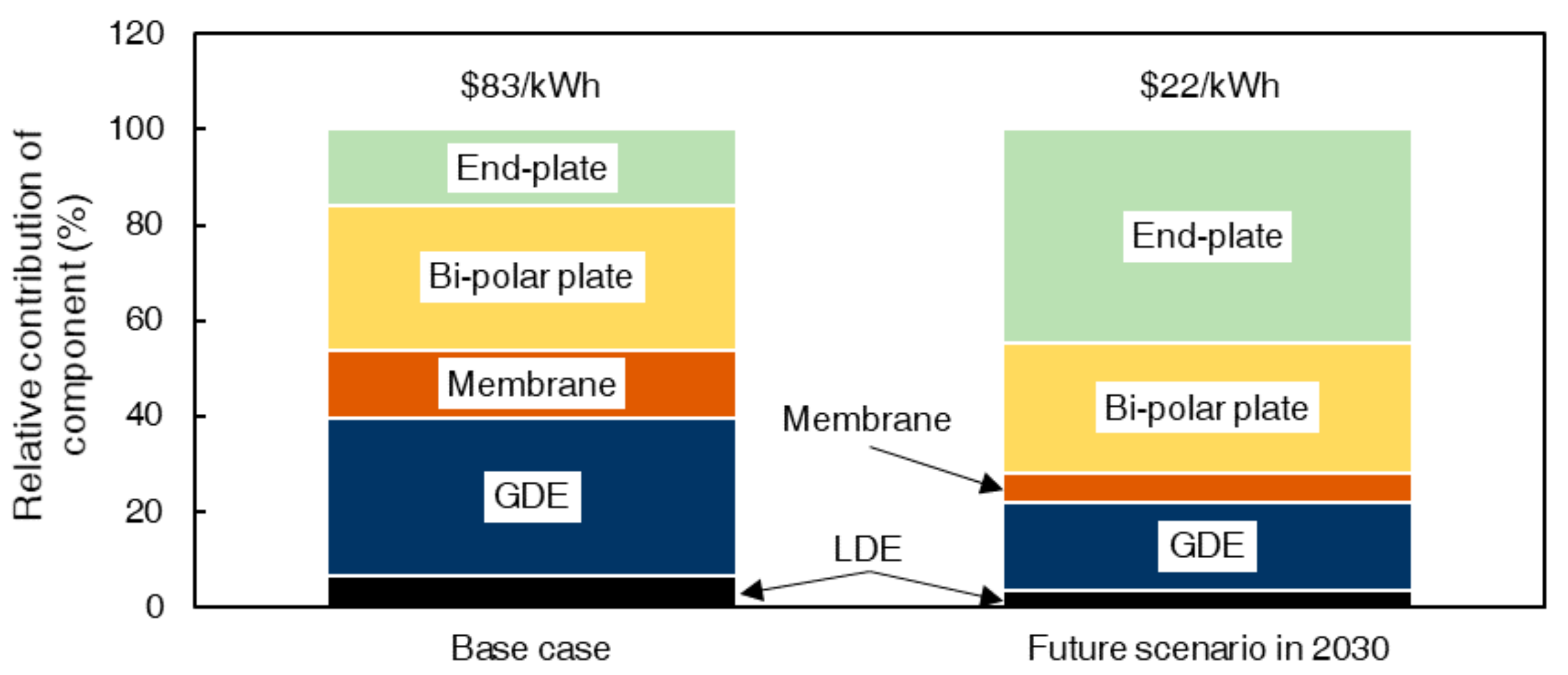
A potential cost reduction roadmap is shown in Figure 3, based on the discussion in Section 3.4. It starts with the base case and subsequently the effects of a reduction in specific component costs are introduced. The last column represents the projected costs for the future case scenario, assuming multiple research innovations and advanced materials are available. Based on these model predictions, we foresee a significant stack cost reduction (~73%) in the future scenario. The costs of the catalyst and the graphite plate and gasket, in particular, have a strong impact on the overall costs. More innovative stack designs will drive down the costs of endplates and stack housing, while lower catalysts loadings will reduce catalyst costs significantly, being the main cost driver for the future case.
In Figure 4, a detailed cost breakdown of the individual components to the total stack costs are presented for the current and future scenarios. The most expensive component of the HBFB stack for the base case is the GDE due to the excessive loading of the noble metal catalyst. This excessive loading is currently used to guarantee catalyst durability and to prevent catalyst degradation in the bromine species-environment [28]. The research challenge is to develop a selective electrocatalyst that is durable, low-cost, and affords low kinetic overpotentials for the HOR/HER reactions, as then the catalyst loading can be reduced. For example, some efforts to engineer molecular sieve barriers that are only selective towards hydrogen are being pursued [14,40]. Another challenge is to develop a more selective ion-exchange membrane to reject bromine species that are highly corrosive towards the electrocatalyst. On this matter, some efforts to fine-tune the ionic channels are also being pursued [31,34,35]. It is expected that with such approaches, the electrocatalyst loading can be as low as in proton exchange membrane (PEM) fuel cell applications (i.e., 0.05 mg Pt/cm2). Because of the high and volatile noble metal price, this development becomes even more important when the required volumes increase. The second major cost component is the graphite plates. As the raw material costs are low and the injection molding process to prepare the plates is common practice, a significant cost reduction upon upscaling is expected.
Finally, in the base case, there is a relatively small contribution from the membrane to the total stack costs. Also here, some cost reduction is still expected. Compared to PEM fuel cells and electrolyzers, the required membrane specifications are less stringent because bromine electrolyte is less oxidative than the oxygen radicals applied in those other systems. Moreover, bromine electrolyte is highly ion-conductive facilitating the transport of protons through the membrane. Less expensive nanoporous membranes were used on a 50 kW pilot-scale system, Flowbox system in France [41].

4.2. HBFB Total System Costs

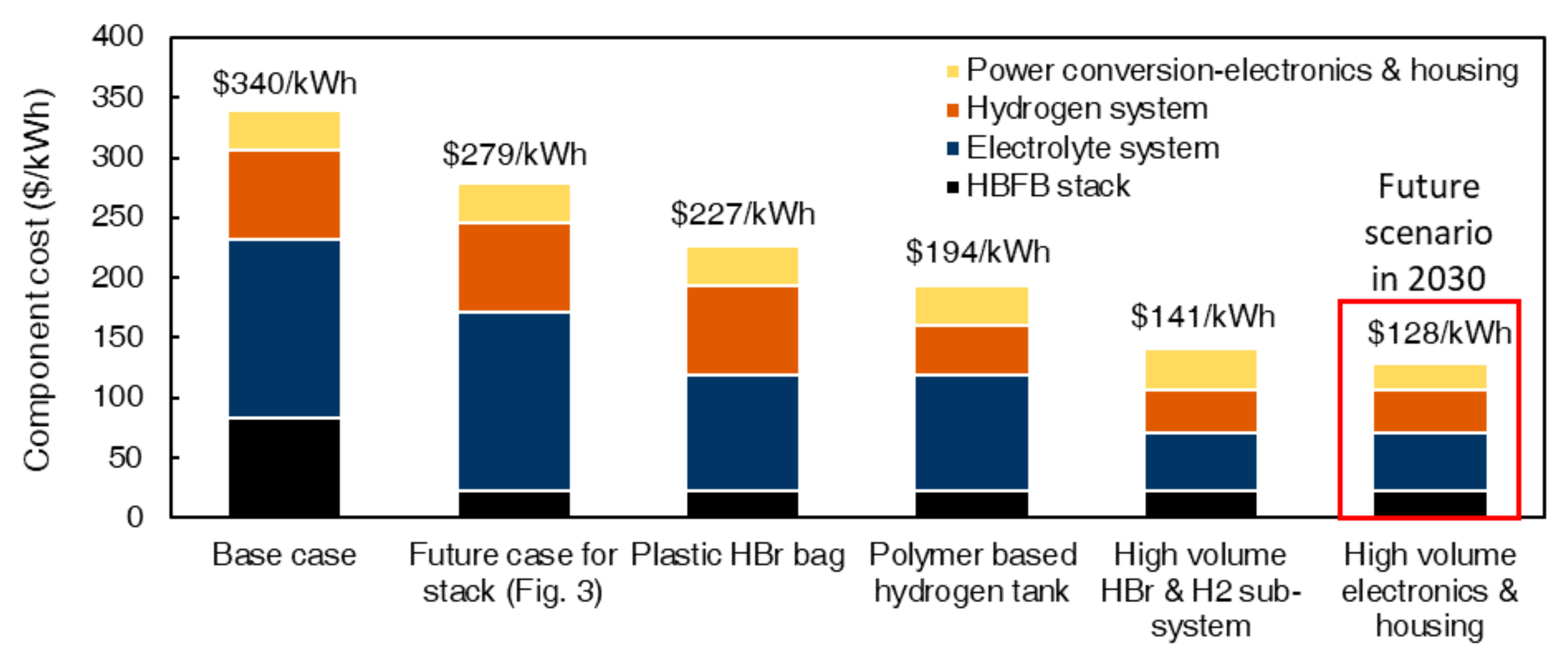
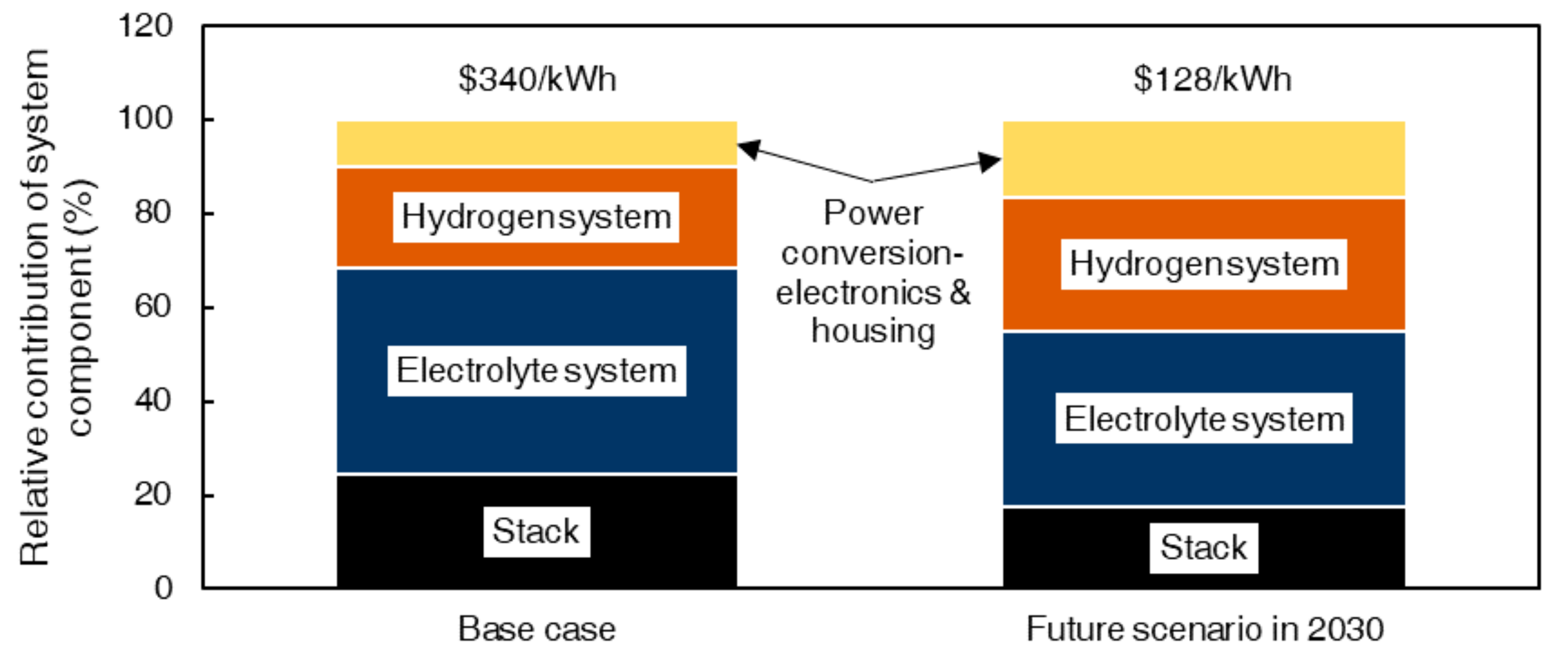
Figure 5 shows the cost reduction roadmap for the total system costs based on the discussion in Section 3.3 while Figure 6 shows the relative contribution of each system component of the HBFB storage system. The HBFB capital investments for the base scenario are $340/kWh and this number is highly competitive compared with a stationary lithium-ion storage system [42]. Based on our predictions, there is a large potential to reduce the system costs and a reduction of ~62% (from $340/kWh to $128/kWh) is expected by 2030.
Although the stack determines the system performance and lifetime, its contribution to the total system costs is only approximately 20% for both the base and the future case, making dedicated system engineering crucial to decrease the costs of storage.
For the base case, the hydrogen and electrolyte systems contribute by 22% and 44%, respectively, to the total capital investment costs of the total system, which is significant. The main challenge is to decrease the costs of storage tanks [17]. The high costs of the hydrogen tank are due to the high requirements in terms of pressure and corrosion resistance, for which a large-scale solution is not available yet. The high costs of the electrolyte tank are mainly due to the highly corrosive nature of the electrolyte. For both, innovation in terms of materials and large-scale production is essential and will significantly reduce the absolute costs, although it is expected that both systems will remain the major contributor to the total system costs, also in the future scenario. We anticipate that ongoing developments by fuel cell automobile manufacturers will facilitate the development of low-cost hydrogen tanks.
Besides a decrease in costs of the stack and tanks, significant cost reductions in other areas are not expected. The electrolyte costs will stay at the same level, as the electrolyte is a commodity chemical already, produced in large volumes. The control system and system housing are also proven solutions. There might be some developments in the bi-directional AC/DC inverter technology that potentially can result in an approximate 50% cost reduction, however, because the contribution of the inverter to the total system costs is relatively small, the impact of this reduction on the total costs will also be minor.

4.3. Cost of Power ($/kW) and Cost of Energy ($/kWh)

The capital costs of a storage system can be subdivided into the costs of power and the costs of energy. Redox flow battery technologies have fundamentally different characteristics than sealed battery technology, e.g., Li-ion batteries. In the former, the cost of power is relatively high, while the costs of energy are lower. The costs of power are mainly based on the costs of the stack components (i.e., the sum of the costs of GDEs, graphite plates, gaskets, membranes, endplates, and LDEs). A sensitivity analysis is performed to identify the major cost-determining component to stimulate research in key areas. Based on the sensitivity analysis (Figure 7), the focus should be reducing the cost of the gas diffusion electrode (by decreasing the loading of catalyst powder) and the cost of the graphite plate and gasket (by lowering the manufacturing cost via injection-molded technique). In this study case, the stack area resistance does not affect the power cost significantly unless there is a technological breakthrough (membraneless HBFBs [43]). The reason is that the stack is operated at a low current density region thus the change in power density is not pronounce. For specific applications (e.g., data centers), it might be required to operate the system at high current density, thus, the stack area resistance must be minimized to ensure that a high voltaic efficiency is maintained. Most importantly, more electrocatalyst engineering efforts and durability studies (including accelerated lifetime tests) are required to improve the electrocatalyst durability and reduce the required catalyst loading for the targeted lifetime.
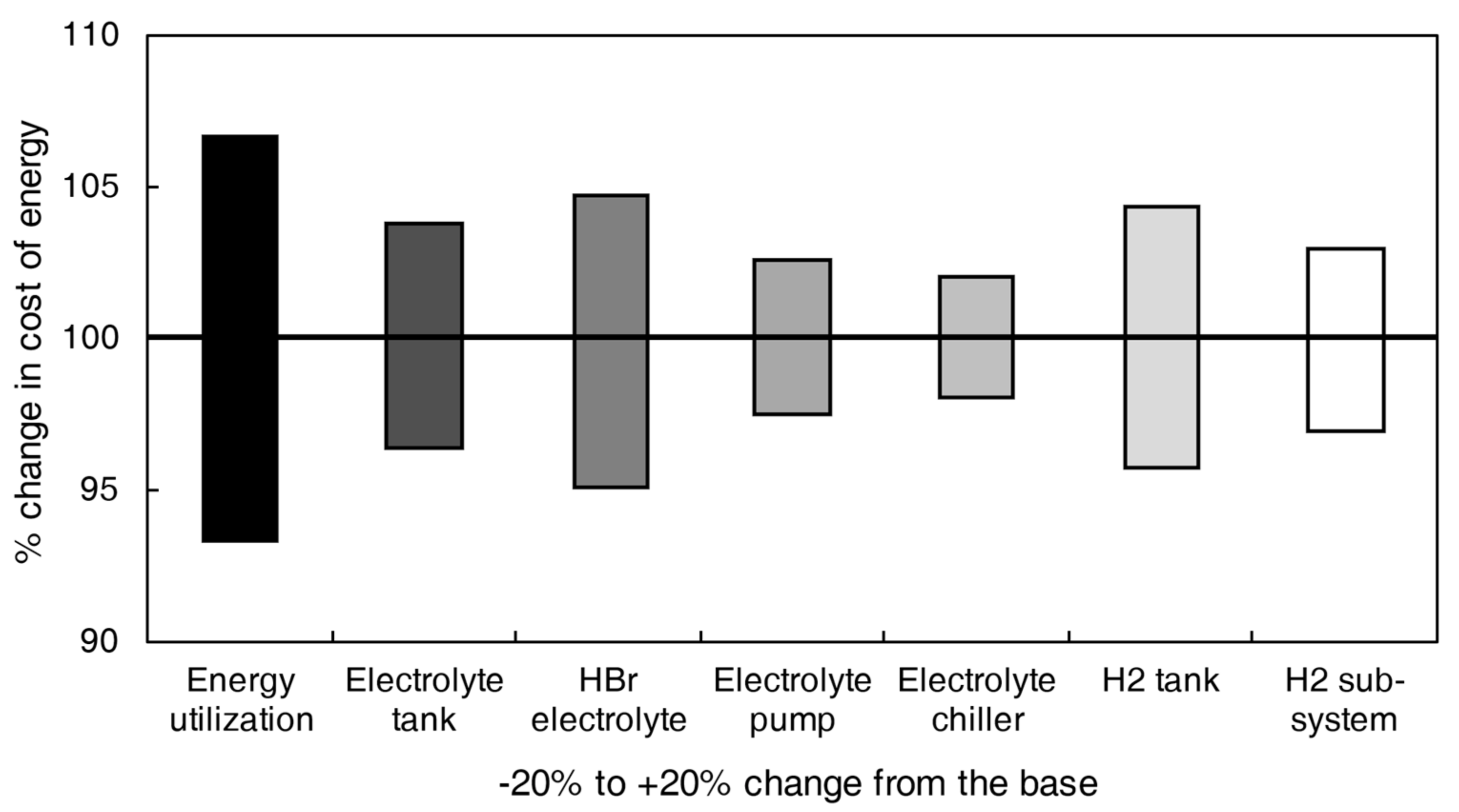
For the cost of energy, there is a huge opportunity to decrease the cost via advanced engineering design. Based on Figure 8, the cost contribution of the H2 tank is comparable to that of the HBr tank and both contribute 25% to the cost of energy. However, the main concern is the stack performance. The higher stack performance results in higher energy utilization. Energy utilization is the relative ratio of the energy that can be discharged from the system (Wh) compared to the energy that is stored in the system (Wh). The sensitivity analysis shows that the stack performance/energy utilization is more important as it affects the size of H2 and HBr tanks and the required HBr volume simultaneously. Therefore, the development effort should focus on improving the stack performance for the cost of energy.
The cost of energy ($/kWh) does not change regardless of the storage time or capacity and only the costs of power ($/kWh) depend on the storage time/capacity. In this case, the capital costs per kWh go down with the increase of storage time/capacity. However, there is a plateau region where the storage time/capacity hardly influences the capital costs because the cost of energy dominates the capital costs per kWh. This plateau region is presented in Figure 9 where the capital costs are plotted as a function of storage time. Figure 9 clearly demonstrates that when the storage time is less than 6 h the capital power costs are dominated by the power costs. Contrary to longer storage times, the energy costs are dictating the overall capital costs. Consequently, below 6 h, the capital cost of power is determinative while for storage times longer than 6 h, the focus should be on decreasing the costs of energy since these contribute more to the capital costs.

4.4. Cash Flow and Levelized Cost of Storage

While the capital investment costs are important for market entry and bankability of the storage system, ultimately, the levelized cost of storage (LCoS) is the most important metric that needs to be minimized to achieve a competitive levelized cost of energy (LCoE) of the WSS system. Here a simplified system is assumed in which the HBFB storage system operates at nominal power (500 kW discharge) and full capacity (full charge followed by full discharge, 5 MWh) at an assumed GDE lifetime of 4000 cycles. The system works for 20 years at a 3% interest rate and a constant electricity price ($0.03/kWh). The corresponding cash flows for the HBFB system per five years for a total period of 20 years are presented in Table 4 for the base case and in Table 5 for the future scenario.
The LCoS is $0.074/kWh for the base case and $0.034/kWh for the future scenario. Assuming that one-third of green electricity produced will be stored for a reliable power supply [7], the LCoE (Equation (7)) for both cases is $0.055/kWh and $0.038/kWh for the base case and the future scenario respectively. Since the most efficient coal-fired power plant produces electricity at $0.05/kWh [5], both the base case and the future scenario, are competitive to the conventional power supply system, especially when also considering the zero-emission benefit.
The other interesting finding when comparing the base case and the future scenario is that the LCoS of the future scenario only decreases by 25% although the capital investment of the future scenario decreases by 62% in comparison to the base case. The main reasons are the complexity of the system, a significant contribution of electricity price on LCoS, and the long project lifetime (20 years).
To assess the effect of the different parameters on the levelized cost of storage, a sensitivity analysis is performed on all factors impacting the LCoS of the system. These data showed that the stack lifetime, the capital investments, and the stack area resistance in particular are the most dominant parameters and have the strongest impact on the LCoS (Figure 10).
For both the base case and future scenario, the trends are similar. It is preferred to reduce capital investments. This does not only play a significant role in the LCoS (Figure 10) but also has a strong impact on market introduction and bankability. As the stack performance (or overall area resistance) affects the capital investment costs directly (size and amount of active area material needed) and indirectly (size of storage tank volume), this is also an important factor with a significant impact on the LCoS.
Figure 10 shows, however, that the stack lifetime (i.e., duration of stack operation) in particular is the most important parameter determining the LCoS. Since a prolonged stack lifetime means a higher cumulative stored energy for the same capital investment, the LCoS goes down. Therefore, stack lifetime, or more specifically electrocatalyst durability and lifetime, is an important parameter that significantly impacts the economic viability of the WSS systems.

5. Conclusions

Techno-economic analysis of a 500 kW/5 MWh HBFB storage system has been performed with the levelized cost of storage approach. The financial viability and bankability of megawatt-scale HBFB are assessed for the introduction of large-scale HBFB systems in the market in both the current case and in the 2030 future scenario. This analysis helps developers to map the current techno-economic status of HBFB technology and its potential in 2030. Hopefully it can can also generate interest in industry and government to accelerate its development and to achieve its potential in 2030. Moreover, it informs the scientific community on outstanding research challenges.
We find that the gas diffusion electrodes and the graphite plates and gaskets dominate the total stack costs, which motivates research into advanced catalytic layers with ultra-low loadings. In terms of total system costs the stack performance should be improved because it reduces the electrolyte tank size and the required HBr solution volume, which are the major system cost contributors. The sensitivity analyses show that the LCoS is most sensitive towards the stack lifetime, so efforts in electrocatalyst development to improve catalyst durability, selective membranes, and long duration testing are needed.
The base case is already competitive with other storage technologies; as regards the base case, the LCoS of the HBFB storage system is $0.074/kWh. For the future scenario $0.03/kWh is foreseen. For a combined wind-solar-storage system, assuming that one-third of the green energy generated will be stored, the LCoS of the system is $0.055/kWh for the base case and $0.038/kWh for the future scenario, making sustainable zero CO2 emission WSS technology highly competitive with fossil fuel-based power generation. Based on these findings, we hope to stimulate scientists from multiple disciplines to develop advanced electrocatalysts with low overpotentials, novel membrane materials, and implement testing protocols for durability tests.

Supplementary Materials

The Suplementary Materials (Supporting Information) are available online at https://www.mdpi.com/2227-9717/8/11/1492/s1, Figure S1: Model stack polarization behavior: (a) I-V curve and contribution of losses and (b) I-V/P curve, Figure S2:Model stack cyclic performance behavior.

Author Contributions

Conceptualization, Y.A.H., A.F.-C., and K.N.; methodology, Y.A.H., A.F.-C., and K.N.; validation, Y.A.H., W.K, G.D., A.F.-C., Z.B., and K.N.; formal analysis, Y.A.; investigation, Y.A., and W.K.; writing-original draft preparation, Y.A.H.; writing-review and editing, Y.A.H., W.K., G.D., A.F.-C., Z.B., and K.N.; visualization, Y.A.H., and W.K.; supervision, G.D., A.F.-C., Z.B., and K.N.; funding acquisition, W.K. All authors have read and agreed to the published version of the manuscript.

Funding

This research was funded by EFRO/OP-Oost under grant number PROJ-000689 (project Hydrous II), European Union Interreg program Deutschland-Nederland with grant number 153098 (project CEC), and the European Union’s Horizon 2020 research and innovation program under grant number 824410 (project GIFT).

Acknowledgments

The authors also would like to thank Elestor B.V. and the team for supplying industrial insights and component cost figures.

Conflicts of Interest

The funders had no role in the design of the study; in the collection, analyses, or interpretation of data; in the writing of the manuscript; or in the decision to publish the results.

References

  1. United Nations Climate Change Paris Agreement 2016. Available online: https://unfccc.int/files/essential_background/convention/application/pdf/english_paris_agreement.pdf (accessed on 22 July 2020).
  2. Communication and roadmap on the European Green Deal; European Commission: Brussels, Belgium, 2019; Available online: https://eur-lex.europa.eu/resource.html?uri=cellar:b828d165-1c22-11ea-8c1f-01aa75ed71a1.0002.02/DOC_1&format=PDF (accessed on 31 October 2020).
  3. The Netherlands Dutch Reflection on the European Green Deal 2019. Available online: https://www.permanentrepresentations.nl/binaries/nlatio/documents/publications/2019/11/25/dutch-reflection-on-the-green-deal/Dutch+Reflection+on+the+Green+Deal+%28nov+2019%29.pdf (accessed on 31 October 2020).
  4. IRENA, Renewable Power Generation Costs in 2018; International Renewable Energy Agency: Abu Dhabi, UAE, 2019; Available online: https://www.irena.org/-/media/Files/IRENA/Agency/Publication/2019/May/IRENA_Renewable-Power-Generations-Costs-in-2018.pdf (accessed on 18 September 2020).
  5. IRENA. Global Energy Transformation: A Roadmap to 2050; International Renewable Energy Agency: Abu Dhabi, UAE, 2018. Available online: https://www.irena.org/-/media/Files/IRENA/Agency/Publication/2018/Apr/IRENA_Report_GET_2018.pdf (accessed on 22 July 2020).
  6. Teplin, C.; Dyson, M.; Engel, A.; Glazer, G. The Growing Market for Clean Energy Portfolios: Economic Opportunities for a Shift from New Gas-Fired Generation to Clean Energy across the United States Electricity Industry; Rocky Mountain Institute: Baslot, CO, USA, 2019; Available online: https://rmi.org/cep-reports (accessed on 29 September 2020).
  7. Fu, R.; Remo, T.; Margolis, R. 2018 U.S. Utility-Scale Photovoltaics-Plus-Energy Storage System Costs Benchmark; National Renewable Energy Laboratory: Golden, CO, USA, 2018. Available online: www.nrel.gov/docs/fy19osti/71714.pdf (accessed on 29 September 2020).
  8. IRENA. Electricity Storage and Renewables: Costs and Markets to 2030; International Renewable Energy Agency: Abu Dhabi, UAE, 2017. Available online: https://www.irena.org/-/media/Files/IRENA/Agency/Publication/2017/Oct/IRENA_Electricity_Storage_Costs_2017_Summary.pdf?la=en&hash=2FDC44939920F8D2BA29CB762C607BC9E882D4E9 (accessed on 21 September 2020).
  9. Zakeri, B.; Syri, S. Electrical energy storage systems: A comparative life cycle cost analysis. Renew. Sustain. Energy Rev. 2015, 42, 569–596. [Google Scholar] [CrossRef]
  10. Chen, H.; Cong, T.N.; Yang, W.; Tan, C.; Li, Y.; Ding, Y. Progress in electrical energy storage system: A critical review. Prog. Nat. Sci. 2009, 19, 291–312. [Google Scholar] [CrossRef]
  11. Cho, K.T.; Albertus, P.; Battaglia, V.; Kojic, A.; Srinivasan, V.; Weber, A.Z. Optimization and Analysis of High-Power Hydrogen/Bromine-Flow Batteries for Grid-Scale Energy Storage. Energy Technol. 2013, 1, 596–608. [Google Scholar] [CrossRef]
  12. Livshits, V.; Ulus, A.; Peled, E. High-power H2/Br2 fuel cell. Electrochem. Commun. 2006, 8, 1358–1362. [Google Scholar] [CrossRef]
  13. Kreutzer, H.; Yarlagadda, V.; van Nguyen, T. Performance evaluation of a regenerative hydrogen-bromine fuel cell. J. Electrochem. Soc. 2012, 159, F331–F337. [Google Scholar] [CrossRef]
  14. Saadi, K.; Nanikashvili, P.; Tatus-Portnoy, Z.; Hardisty, S.; Shokhen, V.; Zysler, M.; Zitoun, D. Crossover-tolerant coated platinum catalysts in hydrogen/bromine redox flow battery. J. Power Sources 2019, 422, 84–91. [Google Scholar] [CrossRef]
  15. Noack, J.; Wietschel, L.; Roznyatovskaya, N.; Pinkwart, K.; Tübke, J. Techno-economic modeling and analysis of redox flow battery systems. Energies 2016, 9, 627. [Google Scholar] [CrossRef]
  16. Dmello, R.; Milshtein, J.D.; Brushett, F.R.; Smith, K.C. Cost-driven materials selection criteria for redox flow battery electrolytes. J. Power Sources 2016, 330, 261–272. [Google Scholar] [CrossRef] [Green Version]
  17. Singh, N.; McFarland, E.W. Levelized cost of energy and sensitivity analysis for the hydrogen–bromine flow battery. J. Power Sources 2015, 288, 187–198. [Google Scholar] [CrossRef]
  18. Yeo, R.S.; Chin, D.T. A Hydrogen-Bromine Cell for Energy Storage Applications. J. Electrochem. Soc. 1980, 127, 549–555. [Google Scholar] [CrossRef]
  19. Trumpf Huttinger TruConvert AC 3020—Power Conversion System. Available online: https://www.trumpf.cn/filestorage/TRUMPF_Master/Products/Power_Electronics/Energy_storage/TRUMPF_Power_conversion_system_TruConvert_AC_3020-EN.pdf.pdf (accessed on 24 January 2020).
  20. Faraday, M., VI. Experimental researches in electricity.-Seventh Series. Philos. Trans. R. Soc. Lond. 1834, 124, 77–122. [Google Scholar] [CrossRef]
  21. Trovò, A.; Marini, G.; Sutto, A.; Alotto, P.; Giomo, M.; Moro, F.; Guarnieri, M. Standby thermal model of a vanadium redox flow battery stack with crossover and shunt-current effects. Appl. Energy 2019, 240, 893–906. [Google Scholar] [CrossRef]
  22. Lin, G.; Chong, P.Y.; Yarlagadda, V.; Nguyen, T.V.; Wycisk, R.J.; Pintauro, P.N.; Bates, M.; Mukerjee, S.; Tucker, M.C.; Weber, A.Z. Advanced Hydrogen-Bromine Flow Batteries with Improved Efficiency, Durability and Cost. J. Electrochem. Soc. 2016, 163, A5049–A5056. [Google Scholar] [CrossRef] [Green Version]
  23. Forner-Cuenca, A.; Penn, E.E.; Oliveira, A.M.; Brushett, F.R. Exploring the Role of Electrode Microstructure on the Performance of Non-Aqueous Redox Flow Batteries. J. Electrochem. Soc. 2019, 166, A2230. [Google Scholar] [CrossRef] [Green Version]
  24. Tariq, F.; Rubio-Garcia, J.; Yufit, V.; Bertei, A.K.; Chakrabarti, B.; Kucernak, A.; Brandon, N. Uncovering the mechanisms of electrolyte permeation in porous electrodes for redox flow batteries through real time in situ 3D imaging. Sustain. Energy Fuels 2018, 2, 2068–2080. [Google Scholar] [CrossRef]
  25. Schweiss, R.; Meiser, C.; Damjanovic, T.; Galbiati, I.; Haak, N. SIGRACET® Gas Diffusion Layers for PEM Fuel Cells, Electrolyzers and Batteries (White Paper); SGL Carbon GmbH: Bonn, Germany, 2016. [Google Scholar]
  26. Nunna, S.; Blanchard, P.; Buckmaster, D.; Davis, S.; Naebe, M. Development of a cost model for the production of carbon fibres. Heliyon 2019, 5, e02698. [Google Scholar] [CrossRef] [PubMed] [Green Version]
  27. Wilson, A.; Kleen, G.; Papageorgopoulos, D. Fuel Cell System Cost—2017; DOE Hydrogen and Fuel Cells Program Record; DOE: Washington, DC, USA, 2017. [Google Scholar]
  28. Hugo, Y.A.; Kout, W.; Sikkema, F.; Borneman, Z.; Nijmeijer, K. In situ long-term membrane performance evaluation of hydrogen-bromine flow batteries. J. Energy Storage 2019, 27, 101068. [Google Scholar] [CrossRef]
  29. Cho, K.T.; Tucker, M.C.; Ding, M.; Ridgway, P.; Battaglia, V.S.; Srinivasan, V.; Weber, A.Z. Cyclic Performance Analysis of Hydrogen/Bromine Flow Batteries for Grid-Scale Energy Storage. ChemPlusChem 2014. [Google Scholar] [CrossRef]
  30. Uchida, M.; Fukuoka, Y.; Sugawara, Y.; Ohara, H.; Ohta, A. Improved Preparation Process of Very-Low-Platinum-Loading Electrodes for Polymer Electrolyte Fuel Cells. J. Electrochem. Soc. 1998, 145, 3708–3713. [Google Scholar] [CrossRef]
  31. Hugo, Y.A.; Kout, W.; Sikkema, F.; Borneman, Z.; Nijmeijer, K. Performance mapping of cation exchange membranes for hydrogen-bromine flow batteries for energy storage. J. Membr. Sci. 2018, 566, 406–414. [Google Scholar] [CrossRef]
  32. Kreuer, K.D. On the development of proton conducting polymer membranes for hydrogen and methanol fuel cells. J. Membr. Sci. 2001, 185, 29–39. [Google Scholar] [CrossRef]
  33. Tucker, M.C.; Cho, K.T.; Spingler, F.B.; Weber, A.Z.; Lin, G. Impact of membrane characteristics on the performance and cycling of the Br2–H2 redox flow cell. J. Power Sources 2015, 284, 212–221. [Google Scholar] [CrossRef] [Green Version]
  34. Park, J.W.; Wycisk, R.; Pintauro, P.N. Nafion/PVDF nanofiber composite membranes for regenerative hydrogen/bromine fuel cells. J. Membr. Sci. 2015, 490, 103–112. [Google Scholar] [CrossRef] [Green Version]
  35. Park, J.W.; Wycisk, R.; Lin, G.; Chong, P.Y.; Powers, D.; van Nguyen, T.; Dowd, R.P., Jr.; Pintauro, P.N. Electrospun Nafion/PVDF single-fiber blended membranes for regenerative H2/Br2 fuel cells. J. Membr. Sci. 2017, 541, 85–92. [Google Scholar] [CrossRef]
  36. Cho, K.T.; Ridgway, P.; Weber, A.Z.; Haussener, S.; Battaglia, V.; Srinivasan, V. High Performance Hydrogen/Bromine Redox Flow Battery for Grid-Scale Energy Storage. J. Electrochem. Soc. 2012, 159, A1806–A1815. [Google Scholar] [CrossRef]
  37. Minke, C.; Hickmann, T.; dos Santos, A.R.; Kunz, U.; Turek, T. Cost and performance prospects for composite bipolar plates in fuel cells and redox flow batteries. J. Power Sources 2016, 305, 182–190. [Google Scholar] [CrossRef]
  38. James, B.D.; Kalinoski, J.A.; Baum, K.N. Mass Production Cost Estimation For Direct H2 PEM Fuel Cell Systesm for Automotive Applications. 2010 Update; Directed Technologies Inc.: Arlington, VA, USA, 2010. [Google Scholar]
  39. The International Flow Battery Forum: Mercure Manchester Piccadilly Hotel, Manchester, UK, 27–29 June 2017; Conference papers; (trading as the International Flow Battery Forum); IFBF Administration Office, Swanbarton Limited: Manchester, UK, 2017.
  40. Li, Y.; Nguyen, T.V. Core-shell rhodium sulfide catalyst for hydrogen evolution reaction/hydrogen oxidation reaction in hydrogen-bromine reversible fuel cell. J. Power Sources 2018, 382, 152–159. [Google Scholar] [CrossRef]
  41. FlowBox. Available online: https://www.innoenergy.com/for-innovators/innoenergy-thematic-fields/energy-storage/flowbox/ (accessed on 22 November 2019).
  42. Wagner, R.; Preschitschek, N.; Passerini, S.; Leker, J.; Winter, M. Current research trends and prospects among the various materials and designs used in lithium-based batteries. J. Appl. Electrochem. 2013, 43, 481–496. [Google Scholar] [CrossRef]
  43. Braff, W.A.; Bazant, M.Z.; Buie, C.R. Membrane-less hydrogen bromine flow battery. Nat. Commun. 2013, 4, 2346. [Google Scholar] [CrossRef] [Green Version]
Figure 1. Schematic diagram of a hydrogen-bromine flow battery (HBFB) cell.
Processes 08 01492 g001
Figure 2. Process flow diagram of the HBFB storage system.
Processes 08 01492 g002
Figure 3. Total stack cost reduction roadmap for the HBFB: from base case to future scenario.
Processes 08 01492 g003
Figure 4. Total HBFB stack component costs and their relative contribution to the total costs for the base case and the future scenario.
Processes 08 01492 g004
Figure 5. Total system cost reduction roadmap for the HBFB: From base case to future scenario.
Processes 08 01492 g005
Figure 6. Total system component costs and the relative contribution of the different system components to these total costs for the base case and the future scenario.
Processes 08 01492 g006
Figure 7. Sensitivity analysis for HBFB component costs of power/stack.
Processes 08 01492 g007
Figure 8. Sensitivity analysis of HBFB component costs of energy.
Processes 08 01492 g008
Figure 9. Effect of storage time on costs of power, costs of energy, and total HBFB capital costs.
Processes 08 01492 g009
Figure 10. Sensitivity analysis of the levelized costs of storage (LCoS) for (a) the base case and (b) future scenario HBFB storage system.
Processes 08 01492 g010
Table 1. Operating conditions for the HBFB storage system.
Operating ConditionParameter
Temperature≤60 °C
CHBr dis.6 M
CHBr ch.2 M
CBr2 dis.0.3 M
CBr2 ch.2.3 M
Br2 stoichiometry ratio≥3
H2 dis.1 bar
H2 ch.8 bar
Table 2. Operating conditions for the HBFB storage system.
ParameterBase CaseFuture CaseUnit
Nominal (dis.) power500500kW
Stack resistance0.300.22Ω·cm2
Current density0.330.33A/cm2
Power density0.2660.274W/cm2
Voltaic efficiency8085%
Coulombic efficiency9799%
Energy efficiency7884%
Pump loss22%
Cooling loss33%
Bi-directional inverter efficiency9696%
System efficiency7077%
Req. active area~210~200m2
Req. electrolyte tank volume7565m3
Table 3. Component costs for the HBFB storage system.
ComponentBase CaseFuture CaseCost Unit
HBFB system
Electrolyte tank564 $/kWh
HBr electrolyte508 $/kWh
Electrolyte pump2521 $/kWh
Electrolyte chiller1815 $/kWh
H2 tank4411 $/kWh
H2 sub-system3026 $/kWh
Bi-directional inverter18080 $/kW
Power electronics45,00038,250 $/unit
Housing33,00028,050 $/unit
System labor150100$/kW
HBFB stack
Liquid diffusion electrode (LDE)13520$/m2
Gas diffusion electrode (GDL)650100$/m2
Replacement LDE250
Membrane28535$/m2
Replacement membrane120
Graphite plate550125$/m2
Gasket5025$/m2
End plate132100 $/kW
Stack labor180100$/m2
Table 4. Cash flow for the base case HBFB storage system.
Cost BreakdownYear
05101520
Cumulative stored energy (MWh)010,00020,00030,00040,000
Capital costs$1,811,090 $115,039
CRF cost $152,238$113,956$113,188$101,394
Maintenance $8,000$8,000$8,000$8,000
Electricity $130,974$130,974$130,974$130,974
Cumulative costs$1,811,090$2,102,302$2,470,270$2,722,432$2,962,800
LCoS (/kWh) $0.210$0.124$0.091$0.074
Table 5. Cash flow for the future scenario HBFB storage system.
Cost BreakdownYear
05101520
Cumulative stored energy (MWh)010,00020,00030,00040,000
Capital costs$712,761 $47,703
CRF cost $59,914$44,848 $44,750 $40,057
Maintenance $8,000$8,000 $8,000 $8,000
Electricity $90,437$90,437 $90,437 $90,437
Cumulative costs$712,761$871,112$1,062,100 $1,205,287 $1,343,781
LCoS (/kWh) $0.087 $0.053 $0.040 $0.034
Publisher’s Note: MDPI stays neutral with regard to jurisdictional claims in published maps and institutional affiliations.