Abstract
This research presents a comprehensive bibliographic review from 2006 through 2020 about the state of the art of the compression–absorption cascade systems for refrigeration. In consequence of this review, this research identifies the significant development of systems that consider lithium bromide as a working fluid; however, the use of other working fluids has not been developed. This study is motivated toward the development of a parametric analysis of the cascade system using NH3-LiNO3, NH3-NaSCN and NH3-H2O in the absorption cycle and R134a in the compression cycle. In this study, the effect of the heat source temperature, condensation temperature in the compression cycle, the use of heat exchangers in the system (also known as economizers) and their contribution to the coefficient of performance is deepened numerically. The economizers evaluated are the following: an internal heat exchanger, a refrigerant heat exchanger, a solution refrigerant heat exchanger, and a solution heat exchanger. Mass and energy balance equations—appropriate equations to estimate the thermophysical properties of several refrigerant–absorbent pairs—were used to develop a thermodynamic model. The studied heat source temperature range was from 355 to 380 K, and the studied condensation temperature range in the compression cycle was from 281 to –291 K; additionally, the importance of each economizer on the coefficient of performance was numerically estimated. In this way, NH3-NaSCN solution in the absorption cycle and R134a in the compression cycle provided promising numerical results with the highest COPs (coefficient of performance).
1. Introduction
In the literature, there are several reviews about vapor compression and innovative thermodynamic cycles for refrigeration as absorption technologies. Srikhirin et al. in 2011 [1] presented a review of absorption refrigeration technologies wherein the authors defined the principle of absorption, i.e., the single-stage, double-stage, half-stage and GAX configurations based on the advances of the time. It is interesting to note the introduction of absorption–compression systems and the thermodynamic cycles which consider a compressor and an ejector within the cycle. Lithium–bromide water and water–ammonia were enlisted as the main working fluids used in these kind of systems. Xu and Wang [2] analyzed four configurations involving absorption cycles with the following configurations analyzed: the single effect cycle, external-circuit coupling cycles, internal-circuit coupling cycles and the cycle combined with an ejector/compressor. The ejector or compressor cycles are used in the combined cycles to boost the cooling efficiency or to lower the temperature. She et al. [3] reviewed seven energy efficient and economic technologies for vapor compression refrigeration systems, in which the objective is to increase thermal efficiency; elements such as: ground heat exchangers, solar panel, cooling towers, desiccant rotor and thermal storage devices are studied throughout the different case studies. Papadopoulos et al. [4] revise the organic working fluids mixtures and the absorption refrigeration cycles available with the aim of generating cooling from the point of view of cleaner and sustainable development. The discussion and recapitulation of the information is intense; it is discussed as a future perspective in which the economic and sustainable prospects for absorption refrigeration cycles must be extended, and additionally, it provides a more reliable estimation of the properties of the working fluids.
As far as the authors are aware, there has been a continuous analysis and modification of compression systems and the absorption cycles separately. This work presents a summary of literature of the main advances in compression–absorption systems for refrigeration, assuming the cascade configuration. A summary is shown in Table 1; the compressive review considers the period from 2006 through 2020 and the contributions of the articles [5,6,7,8,9,10,11,12,13,14,15,16,17,18,19,20,21,22,23]. As can be seen, the research line on cascade configuration involving the absorption cycle and compression cycle has been growing over time, and mainly carried out in the theoretical and thermodynamic field.

Table 1.
A compressive review of cascade refrigeration cycles with an emphasis on used economizers.
The main trends that have been reported over time in the study of this class of systems are:
- The refrigerant–absorbent pair commonly worked is LiBr-H2O and NH3-H2O. Fernández-Seara et al. [5] and Cimsit et al. [7] developed simulations with NH3-H2O, presenting advantages and disadvantages regarding to LiBr-H2O.
- The refrigerant that has been considered most frequently in the compression cycle is R134a, and less the NH3. Recently, models and designs have been reported that involve R410a, as in the work of Boyaghchi et al. [12]. Additionally, it proposes the use of H2O/Cu oxide (CuO) nanofluid as a fluid that transports energy from a solar collector to the generator.
- New configurations have been proposed, which involve double-effect absorption or the satisfaction of specific refrigeration applications as food conservation, cooling in naval ships, or solar energy coupled into the cascade system. These designs consider LiBr- H2O in the absorption cycle. An aspect that has caught our attention is the fact that the number of heat exchangers (also known as economizers) that the system must involve has not been identified. Additionally, the heat exchanger effectiveness changes from author to author, in ranges from 0.6 to 0.85.
The relevant differences and novelties studies by Cimsit et al. [7], Boyaghchi et al. [12], Jain et al. [17], Karamangil et al. [24] and the present work are:
- Thermodynamic analysis and simulation were presented by Cimsit et al. [7], Jain et al. [17], and Boyaghchi et al. [12] considering LiBr-H2O as the working fluid in the absorption cycle in several conditions, and the design consideration of solution heat exchanger. Then, Cimsit et al. [7] simulated the coefficient of the system performance considering NH3-H2O; while this work proposes an extension of the knowledge of Cimsit et al. [7] adding the evaluation of NH3-LiNO3, NH3-NaSCN in the absorption cycle.
- The works carried out by Karamangil et al. [24] can be compared with the present manuscript, developing a thermodynamic model of a visual software package to analyze the absorption single-stage refrigerant system. The solutions under study were H2O-LiBr, NH3-H2O, NH3-LiNO3, and acetone-ZnBr2, while this study presents a theoretical thermodynamic model to compute the energy efficiency parameters in the compression–absorption cascade system considering the influence of several economizers. The energy balance equation and the coefficient of performance were considered in both papers as comparison parameters.
- To the extent of our knowledge, the refrigerant–absorbent pair selected in this manuscript were NH3-LiNO3 and NH3-NaSCN for the first time for the compression–absorption system, the numerical results are compared with NH3-H2O performance; while R134a refrigerant remains in the compression cycle.
The energy balance equation and the coefficient of performance were considered in both papers as comparison parameters. In the works previously presented, an aspect that has caught our attention is the fact that the number of heat exchangers (also known as economizers) that the system must involve has not been identified; also, the heat exchanger effectiveness changes from author to author, in ranges from 0.6 to 0.9. The goal is to show the influence of the economizer’s effectiveness and present a performance evaluation of each exchanger within a compression–absorption cascade system.
2. System Description
The compression–absorption cascade system for refrigeration presented in this work consists of nine main components: a generator, a solution heat exchanger (SHE), an absorber, a solution refrigerant heat exchanger (SRHE), a condenser, a refrigerant heat exchanger (RHE), a cascade heat exchanger, an internal heat exchanger (IHE), a compressor and an evaporator showed in Figure 1. This kind of system is based on the union of two cycles in a cascade configuration, the absorption cycle needs two fluids: a substance capable of high absorption capacity and the refrigerant, which is capable of being evaporated and condensed with relative ease. Waste heat is used to separate the working fluid from the absorbent in the generator; a vapor stream is directed to the condenser at state 1, while the strong solution (with a high concentration of absorbent) goes to the absorber at state 12. Then, the refrigerant condenses at state 3 and its pressure is reduced to feed the cascade heat exchanger. On the one hand, isobaric evaporation is carried out in the cascade heat exchanger to produce a vapor stream at state 6; it is taken to produce absorption with the arrival of a strong solution to get a weak solution. The weak solution is pumped at state 9 to state 11 to finish the absorption cycle. On the other hand, for the cascade heat exchanger, the refrigerant at state 15 is isobarically condensed to state 16. The pressure of the refrigerant is reduced in the expansion valve to the evaporator pressure level. The evaporation of refrigerant from states 18 to 19 produces the main product of the entire system, the refrigeration effect. Then, the vapor stream is subject to mechanic compression to finish the refrigerant cycle. As can be seen, four heat exchangers were added in the configuration of the cascade system; they have the main objective of taking advantage of the temperature differential in the system and consequently to increase the coefficient of performance. The four economizers are described as following:
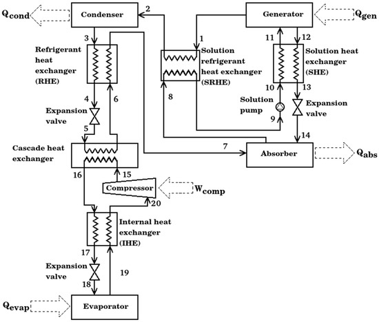
Figure 1.
Schematic diagram of compression–absorption cascade system with four economizers.
- Internal heat exchanger. Its objective is to reduce the work added by the compressor to the cycle, it exchanges the heat transfer from high pressure compressed liquid to saturated steam to low pressure; all previously in the compression cycle.
- Refrigerant heat exchanger. This heat exchanger was designed to increase the energy of the vapor stream at the cascade heat exchanger outlet, taking advantage of the condensed liquid obtained from the condenser.
- Solution refrigerant heat exchanger. This type of equipment is designed to operate between the two pressure levels of the absorption cycle, the strong LiBr solution and the refrigerant vapor are the working fluids that flow in the equipment. Solution heat exchanger. It is the heat exchanger commonly used in the literature for absorption cycles; its function is to preheat the solution from the absorber to the generator. Its use increases the use of the waste heat added in the generator.
3. Thermodynamic Modeling
Considering the characteristics of the cascade cycle, the following assumptions have been declared:
- In the absorption cycle, the pump work necessary to circulate the solution is considered negligible [7].
- Pressure and temperature values could be worked with experimentally [9].
- Steady-state conditions are considered in this study.
- Thermodynamic equilibrium at the inlet and outlet of the components is assumed
- The heat losses from the equipment, the pressure drop in the piping, and the main components are considered negligible [20].
- The expansion process in the valve is considered isenthalpic.
- Solutions flowing out of the absorber and the generator are assumed to be saturated in equilibrium conditions at their respective temperatures and concentrations [24].
The principles of mass and energy conservation are developed for each component of the cascade system. The governing equations for a steady flow system are given according to the following equations.
The mass conservation:
where m represents the mass flow rate in (kg/s) that goes in and out into control volume.
The conservation of species in the solution are depicted according to the following equation:
where x is mass concentration of solution in the absorption cycle.
The first law of the thermodynamics was applied according to the following equation:
where h is the specific enthalpy in (kJ/kg) at each state point, Q the heat load that goes in and out into control volume in (kW), and W the work in (kW).
The coefficient of performance was determined as the refrigeration capacity () per unit of heat and work added in the generator () plus compressor (). The following provides the calculation of coefficient of performance (COP):
For the calculation of thermophysical properties of the solution and working fluids considering in this study, the following references were used:
- The NH3-H2O thermophysical properties are obtained from the correlations provided by M. Conde Engineering [25].
- The NH3-LiNO3 thermophysical properties are evaluated by functions obtained by Libotean et al. [26,27] for vapor pressure, density and specific heat capacity,
- Infante Ferreira’s [28] correlation has been used to obtain the specific enthalpy of solution.
- For the NH3-NaSCN solution, vapor pressure and enthalpy correlation equation coefficients provided by D Cai et al. [29] and
- The correlation of density was provided by Chaudhari et al. [30]
Furthermore, the calculation of the thermophysical properties of the NH3 and R134a is achieved through a coupling with the “Coolprop” open-source thermodynamic properties database [31].
In accordance with previous hypotheses, the balances of mass, energy, and thermophysical properties calculation for each system, besides the simulation code and thermodynamic analysis are presented next.
4. Results and Discussion
This section presents the main numerical results in the following order: (1) comparison between the numerical results of this research and a model reported by other authors, (2) thermodynamic results in each state of the entire system for future design, (3) the effect of the heat source temperature, evaporation temperature in the compression cycle, the heat exchanger effectiveness, and the contribution of each economizer in the cascade system.
4.1. Model Validation
For validation of the present work, the simulation results are compared with research work reported by Cimsit and Ozturk [7], which is presented in Table 2. The relative error was calculated for each item available; the following equation was applied:
Table 2.
Comparison of present model with model by Cimsit and Ozturk [7].
The evaluated energy flow rates in all parts of the system are according to [7]. A maximum relative error was calculated to 0.0287. Agreement in values of COP, heat flow, and work in the components prove that the model is appropriate.
4.2. Thermodynamic Results of Base-Case Exposed in This Work
Table 3, Table 4 and Table 5 show the thermodynamic data for the compression–absorption system with four economizers operating with NH3-LiNO3, NH3-NaSCN and NH3-H2O solutions in the absorption cycles and R134a in the compression cycle, all under the conditions of Tgen = 363 K, Tevap1 = 263 K, Tabs = Tcon1 = 313 K, εHX’s = 0.8, 50 kW of refrigeration load.
Table 3.
Thermodynamic data of the compression–absorption cascade system using NH3-LiNO3 solution and R134a as working fluid.
Table 4.
Thermodynamic data of the compression–absorption cascade system using NH3-NaSCN solution and R134a as working fluid.
Table 5.
Thermodynamic data of the compression–absorption cascade system using NH3-H2O solution and R134a as working fluid.
Table 6 shows a comparison between the heat capacities and work of the components of the proposed cascade cycles, and the traditional vapor compression refrigeration cycle. As can be seen, for the same cooling load, there is a decrease in the compressor work of 51.46%, it is the main reason why the COP increases.
Table 6.
Thermal capacity and performance of the compression–absorption system and traditional vapor compression refrigeration cycle.
4.3. Effect of the Heat Source Temperature, Evaporation Temperature in the Compression Cycle and the Contribution of Each Economizer in the Cascade System
Figure 2 shows the coefficient of performance for the compression–absorption systems as a function of the heat source temperature; for simulation T16 = 291 K and T6 = 283 K remains constant. For the numerical results, three evaporation temperatures in the absorption cycle were selected: 253 K, 263 K, and 273 K. As can be seen, for all working fluids, if the evaporation temperature increases the COP increases. The performance of the cycles that consider NH3-H2O and NH3-LiNO3 are very similar, and even the same for heat source temperature higher than 365 K. The COPs are approximately 13.3% higher for of compression–absorption system considering NH3-NaSCN than those obtained with NH3-H2O.
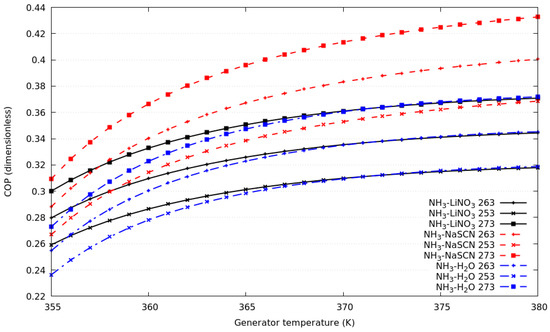
Figure 2.
Coefficient of performance against generator temperature for evaporation temperature in the absorption cycle of 253 K, 263 K and 273 K.
Figure 3 shows the coefficient of performance against the T16 from 281 K to 291 K for all systems described above. The simulation considers, simultaneously, a change of T6 from 273 to 283 K, which allows us to maintain a temperature differential of 8 K between the condensation temperature in the compression cycle and evaporation temperature in the absorption cycle. It can be observed that the COPs increase with an increase of T16 keeping the consideration described for the cascade heat exchanger effectiveness constant.
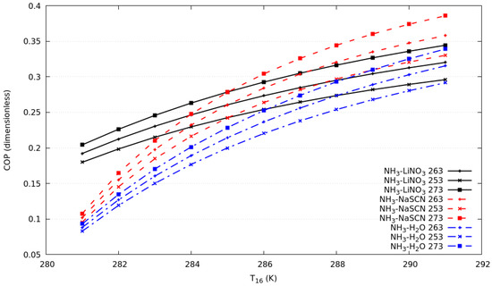
Figure 3.
Coefficient of performance against T16 in compression cycle for evaporation temperature in the absorption cycle of 253 K, 263 K and 273 K.
The results in Figure 4 can explain the increase in COP. The COP in the compression cycle is reduced, due to the increase in the pressure difference and the work of the compressor. This behavior is the same for all the systems under study, because R134a is used in the compression cycle. Figure 4 illustrates the COP in the absorption cycle, it increases due to the increase of T6 in the simulation. As can be seen, in the range of T16 from 281 to 285 K the system with the highest COP was NH3-LiNO3, while in the range of T16 from 285 to 291 K the system with the highest COP was NH3-NaSCN. This is evidence that the combination of NH3-NaSCN would show the best performance when the compressor consumption increases and COP in the compression cycle decreases.
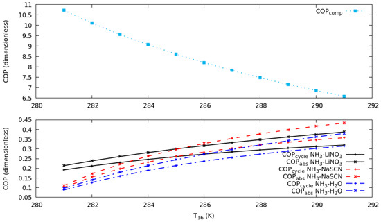
Figure 4.
Coefficient of performance in the compression and absorption cycles against T16 in compression cycle for T19 of 263 K.
Figure 5 depicts the comparison of all compression–absorption systems considered in this study, the plot considers a heat exchanger with known effectiveness from 0 to 1, and its corresponding coefficient of performance is calculated. As it can be seen, the system with the highest coefficient of performance is the system with the NH3-NaSCN solution in the absorption cycle and R134a in the compression cycle; a similar trend has systems that consider NH3-H2O and NH3-LiNO3 in the absorption cycle; in the range under study, their discrepancy is less than 6.5%. As shown, the much higher improvement in COP was calculated considering the SHE compared to RHE, SHRE and IHE; for all simulations, the use of IHE could be considered negligible when deciding to build the compression–absorption cascade system. Special attention should be paid to SHE, as it is the heat exchanger that showed a significant contribution in the COP. The results of the coefficient of performance for the compression–absorption cascade system using NH3-LiNO3 solution and R134a refrigerant as working fluids are described. The COP increases rapidly when the solution heat exchanger is used, an increase of ≈42% is calculated when the solution heat exchanger increases from 0.6 to 0.85. If the refrigerant heat exchanger is only considered, the COP increases ≈2.9% when the heat exchanger’s effectiveness was increased from 0.6 to 0.85. The use of the refrigerant solution heat exchanger and internal heat exchanger does not represent a significant contribution to the increase in COP. The behavior of the coefficient of performance of the compression–absorption cascade system considering each one of the economizers using the NH3-NaSCN solution and the R134a refrigerant as working fluids are analyzed. The heat exchanger effectiveness is changed in the range of 0 to 1, as depicted in Figure 5. If the heat exchanger effectiveness is fixed to 0.8, a common value for clean and new heat exchangers, the greatest contribution to the coefficient of performance was made by the solution heat exchanger, followed by the refrigerant heat exchanger and solution refrigerant heat exchanger. The contribution of the internal heat exchanger was insignificant. The maximum point of the coefficient of performance was 0.479 considering the heat exchanger effectiveness equal to 0.8. As can be seen, the coefficient of performance in the compression–absorption cascade system considering the NH3-H2O solution and R134a as working fluids increased linearly when the refrigerant heat exchanger, solution refrigerant heat exchanger and internal heat exchanger were simulated. According to what is illustrated in Figure 5c, the influence of the solution heat exchanger of the entire coefficient of performance produces an increase from 0.319 to 0.45 when the heat exchanger effectiveness was increased from 0 to 0.8.
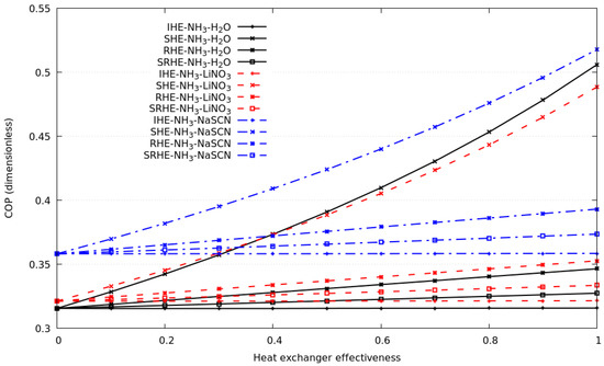
Figure 5.
The coefficient of performance against heat exchanger effectiveness for each of the economizers considering all solutions and R134a as working fluid.
5. Conclusions
A compressive and synthesized literature review and thermodynamic modeling of the compression–absorption cascade system considering several economizers were carried out for refrigeration purposes using NH3-LiNO3, NH3-NaSCN, NH3-H2O, and R134a as working fluids. The main results of the present paper are the following:
- For the refrigerant–absorbent pairs considered in this analysis, NH3-NaSCN in the absorption cycle and R134a in the compression cycle showed the highest coefficient of performances considering the heat source temperature and evaporator temperature conditions described in this work.
- Approximately 50% of the work consumed in the compressor can be reduced in a cascade system using NH3-NaSCN and R134a as working fluids, compared to a traditional vapor compression refrigeration system.
- The solution heat exchanger was the economizer that significantly benefits the coefficient of performance of the compression–absorption cascade system for all working fluids under study. The refrigerant heat exchanger is the economizer that secondly contributes a benefit to the performance of the entire system. The correct selection, cleaning, and maintenance of these economizers is suggested, to guarantee a greater heat exchanger effectiveness than 0.6.
- The contribution of a solution refrigerant and an internal heat exchanger was not theoretically significant in the coefficient of performance for all working fluids under study.
Future research could consider the theoretical study of the compression cycle and double-effect-absorption cycles in the cascade configuration using NH3-LiNO3, NH3-NaSCN, NH3-H2O and eco-friendly refrigerants in the compression cycle.
Author Contributions
J.H.-R. oversaw conceptualization, methodology, analysis of results, and writing—original draft preparation; D.C.-G. oversaw data curation, writing—reviewing, supervision, analysis of results, reviewing—editing, and project administration. All authors have read and agreed to the published version of the manuscript.
Funding
This research received no external funding.
Conflicts of Interest
The authors declare that they have no known competing financial interests or personal relationships that could have appeared to influence the work reported in this paper.
References
- Srikhirin, P.; Aphornratana, S.; Chungpaibulpatana, S. A review of absorption refrigeration technologies. Renew. Sustain. Energy Rev. 2001, 5, 343–372. [Google Scholar] [CrossRef]
- Xu, Z.Y.; Wang, R.Z. Absorption refrigeration cycles: Categorized based on the cycle construction. Int. J. Refrig. 2016, 62, 114–136. [Google Scholar] [CrossRef]
- She, X.; Cong, L.; Nie, B.; Leng, G.; Peng, H.; Chen, Y.; Zhang, X.; Wen, T.; Yang, H.; Luo, Y. Energy-efficient and-economic technologies for air conditioning with vapor compression refrigeration: A comprehensive review. Appl. Energy 2018, 232, 157–186. [Google Scholar] [CrossRef]
- Papadopoulos, A.I.; Kyriakides, A.S.; Seferlis, P.; Hassan, I. Absorption refrigeration processes with organic working fluid mixtures-a review. Renew. Sustain. Energy Rev. 2019, 109, 239–270. [Google Scholar] [CrossRef]
- Fernandez-Seara, J.; Sieres, J.; Vazquez, M. Compression–absorption cascade refrigeration system. Appl. Ther. Eng. 2006, 26, 502–512. [Google Scholar] [CrossRef]
- Garimella, S.; Brown, A.M.; Nagavarapu, A.K. Waste heat driven absorption/vapor-compression cascade refrigeration system for megawatt scale, high-flux, low-temperature cooling. Int. J. Refrig. 2011, 34, 1776–1785. [Google Scholar] [CrossRef]
- Cimsit, C.; Ozturk, I.T. Analysis of compression–absorption cascade refrigeration cycles. Appl. Ther. Eng. 2012, 40, 311–317. [Google Scholar] [CrossRef]
- Colorado, D.; Velazquez, V.M. Exergy analysis of a compression–absorption cascade system for refrigeration. Int. J. Energy Res. 2013, 37, 1851–1865. [Google Scholar] [CrossRef]
- Cimsit, C.; Ozturk, I.T.; Kincay, O. Thermoeconomic optimization of LiBr/H2O-R134a compression-absorption cascade refrigeration cycle. Appl. Ther. Eng. 2015, 76, 105–115. [Google Scholar] [CrossRef]
- Colorado, D.; Rivera, W. Performance comparison between a conventional vapor compression and compression-absorption single-stage and double-stage systems used for refrigeration. Appl. Ther. Eng. 2015, 87, 273–285. [Google Scholar] [CrossRef]
- Jain, V.; Sachdeva, G.; Kachhwaha, S.S.; Patel, B. Thermo-economic and environmental analyses based multi-objective optimization of vapor compression–absorption cascaded refrigeration system using NSGA-II technique. Energy Convers. Manag. 2016, 113, 230–242. [Google Scholar] [CrossRef]
- Boyaghchi, F.A.; Mahmoodnezhad, M.; Sabeti, V. Exergoeconomic analysis and optimization of a solar driven dual-evaporator vapor compression-absorption cascade refrigeration system using water/CuO nanofluid. J. Clean. Prod. 2016, 139, 970–985. [Google Scholar] [CrossRef]
- Dixit, M.; Arora, A.; Kaushik, S.C. Energy, exergy, environment and economic analyses and optimization of two-stage absorption–compression combined refrigeration system. Clean Technol. Environ. Policy 2017, 19, 2215–2229. [Google Scholar] [CrossRef]
- Cimsit, C. Thermodynamic performance analysis of the double effect absorption-vapour compression cascade refrigeration cycle. J. Therm. Sci. Technol. 2018, 13, JTST0007. [Google Scholar] [CrossRef]
- Salhi, K.; Korichi, M.; Ramadan, K.M. Thermodynamic and thermo-economic analysis of compression–absorption cascade refrigeration system using low-GWP HFO refrigerant powered by geothermal energy. Int. J. Refrig. 2018, 94, 214–229. [Google Scholar] [CrossRef]
- Vasta, S.; Palomba, V.; La Rosa, D.; Mittelbach, W. Adsorption-compression cascade cycles: An experimental study. Energy Convers. Manag. 2018, 156, 365–375. [Google Scholar] [CrossRef]
- Jain, V.; Sachdeva, G.; Kachhwaha, S.S. Comparative performance study and advanced exergy analysis of novel vapor compression-absorption integrated refrigeration system. Energy Convers. Manag. 2018, 172, 81–97. [Google Scholar] [CrossRef]
- Turgut, M.S.; Turgut, O.E. Comparative investigation and multi objective design optimization of a cascaded vapor compression absorption refrigeration system operating with different refrigerants in the vapor compression cycle. Heat Mass Transfer. 2019, 55, 467–488. [Google Scholar] [CrossRef]
- Mahalle, K.; Parab, P.; Bhagwat, S. Optimization of cooling load in the combined vapour absorption–vapour compression refrigeration cycle using exergy analysis. Indian Chem. Eng. 2019, 61, 52–66. [Google Scholar] [CrossRef]
- Colorado-Garrido, D. Advanced Exergy Analysis of a Compression–Absorption Cascade Refrigeration System. J. Energy Res. Technol. 2019, 141. [Google Scholar] [CrossRef]
- Jing, Y.; Li, Z.; Chen, H.; Lu, S.; Lv, S. Exergoeconomic design criterion of solar absorption-subcooled compression hybrid cooling system based on the variable working conditions. Energy Convers. Manag. 2019, 180, 889–903. [Google Scholar] [CrossRef]
- Zoghi, M.; Habibi, H.; Chitsaz, A.; Javaherdeh, K.; Ayazpour, M. Exergoeconomic analysis of a novel trigeneration system based on organic quadrilateral cycle integrated with cascade absorption-compression system for waste heat recovery. Energy Convers. Manag. 2019, 198, 111818. [Google Scholar] [CrossRef]
- Sun, Z.; Wang, C.; Liang, Y.; Sun, H.; Liu, S.; Dai, B. Theoretical study on a novel CO2 Two-stage compression refrigeration system with parallel compression and solar absorption partial cascade refrigeration system. Energy Convers. Manag. 2020, 204, 112278. [Google Scholar] [CrossRef]
- Karamangil, M.I.; Coskun, S.; Kaynakli, O.; Yamankaradeniz, N. A simulation study of performance evaluation of single-stage absorption refrigeration system using conventional working fluids and alternatives. Renew. Sustain. Energy Rev. 2010, 14, 1969–1978. [Google Scholar] [CrossRef]
- M. Conde Engineering. Thermophysical Properties of {NH3 + H2O} Mixtures for Industrial Design of Absorption Refrigeration Equipment. Formulation for Industrial use. 2008. Available online: http://www.mrc-eng.com/Downloads/NH3&H2O%20%20Props%20English.pdf (accessed on 30 March 2020).
- Libotean, S.; Salavera, D.; Valles, M.; Esteve, X.; Coronas, A. Vapour-liquid equilibrium of ammonia + lithium nitrate + water and ammonia + lithium nitrate solutions from (293.15 to 353.15) K. J. Chem. Eng. Data 2007, 52, 1050–1055. [Google Scholar] [CrossRef]
- Libotean, S.; Martiín, A.; Salavera, D.; Valles, M.; Esteve, X.; Coronas, A. Densities, viscosities, and heat capacities of ammonia+ lithium nitrate and ammonia+ lithium nitrate+ water solutions between (293.15 and 353.15) K. J. Chem. Eng. Data 2008, 53, 2383–2388. [Google Scholar] [CrossRef]
- Ferreira, C.I. Thermodynamic and physical property data equations for ammonia-lithium nitrate and ammonia-sodium thiocyanate solutions. Sol. Energy 1984, 32, 231–236. [Google Scholar] [CrossRef]
- Cai, D.; He, G.; Tian, Q.; Tang, W. Exergy analysis of a novel air-cooled non-adiabatic absorption refrigeration cycle with NH3–NaSCN and NH3–LiNO3 refrigerant solutions. Energy Convers. Manag. 2014, 88, 66–78. [Google Scholar] [CrossRef]
- Chaudhari, S.K.; Salavera, D.; Coronas, A. Densities, viscosities, heat capacities, and vapor–liquid equilibria of ammonia+ sodium thiocyanate solutions at several temperatures. J. Chem. Eng. Data 2011, 56, 2861–2869. [Google Scholar] [CrossRef]
- Bell, I.H.; Wronski, J.; Quoilin, S.; Lemort, V. Pure and pseudo-pure fluid thermophysical property evaluation and the open-source thermophysical property library CoolProp. Ind. Eng. Chem. Res. 2014, 53, 2498–2508. [Google Scholar] [CrossRef]


© 2020 by the authors. Licensee MDPI, Basel, Switzerland. This article is an open access article distributed under the terms and conditions of the Creative Commons Attribution (CC BY) license (http://creativecommons.org/licenses/by/4.0/).