Article

Investigation of the Performance and Emission Characteristics of a Diesel Engine with Different Diesel–Methanol Dual-Fuel Ratios

1
School of Mechanical and Automotive Engineering, Guangxi University of Science and Technology, Liuzhou 545006, China
2
United Automotive Electronic Systems Co., Ltd. Liuzhou Branch, Liuzhou 545006, China
*
Author to whom correspondence should be addressed.
Processes 2021, 9(11), 1944; https://doi.org/10.3390/pr9111944
Submission received: 8 October 2021 / Revised: 28 October 2021 / Accepted: 28 October 2021 / Published: 29 October 2021
(This article belongs to the Special Issue Clean Combustion and Emission in Vehicle Power System)

Abstract

:
In this paper, the effects of different diesel–methanol blends on the combustion and emission characteristics of diesel engines are investigated in terms of cylinder pressure, heat release rate, cylinder temperature, brake specific fuel consumption, thermal brake efficiency, brake power, and soot, nitrogen oxides, and carbon monoxide emissions in a four-stroke diesel engine. The corresponding three-dimensional Computational Fluid Dynamics (CFD) model was established using the Anstalt für Verbrennungskraftmaschinen List (AVL)-Fire coupled Chemkin program, and the chemical kinetic mechanism, including 135 reactions and 77 species, was established. The simulation model was verified by the experiment at 50% and 100% loads, and the combustion processes of pure diesel (D100) and diesel–methanol (D90M10, D80M20, and D70M30) were investigated, respectively. The results showed that the increase in methanol content in the blended fuel significantly improved the emission and power characteristics of the diesel engine. More specifically, at full load, the cylinder pressures increased by 0.78%, 1.21%, and 1.41% when the proportions of methanol in the blended fuel were 10%, 20%, and 30%, respectively. In addition, the power decreased by 2.76%, 5.04%, and 8.08%, respectively. When the proportion of methanol in the blended fuel was 10%, 20%, and 30%, the soot emissions were decreased by 16.45%, 29.35%, and 43.05%, respectively. Therefore, methanol content in blended fuel improves the combustion and emission characteristics of the engine.

1. Introduction

Due to the durability, reliability, and high efficiency of diesel engines [1], they are widely used in industry, the military, transportation, and other fields [2]. To date, the diesel engine has contributed to social productivity, social material civilization, national economic development, and people’s lifestyles. However, it has also brought a series of social and environmental problems to our life [3]. For example, the NOx emission of diesel engines accounts for 70% of the total vehicle emissions [4]. Therefore, in the face of the global energy crisis and environmental crisis, how to effectively reduce the emission of harmful gases from diesel engines is an urgent problem to be solved [5].
At present, there are three main technical schemes for the emission reduction of diesel engines [6]. The first is advanced internal combustion engine technology [7]. The second is aftertreatment technology such as urea selective catalytic reduction [8] and diesel oxidation catalysts [9]. The third is alternative fuels such as natural gas [10] and methanol [11]. Due to increasingly stringent emission regulations and the energy crisis, alternative fuels for many diesel engines have been widely developed and studied in recent years [12]. Alcohol mixed with traditional petrochemical fuel can reduce soot and nitrogen oxides at the same time and thus, it has attracted extensive attention in recent years [13,14].
Methanol is a clean energy, which can be produced from hydrogen and carbon dioxide by solar energy and realize carbon neutrality [15]. In addition, methanol can be produced on a large scale. Its unique physical and chemical properties can effectively reduce the formation of particles, nitrogen oxides, and unburned hydrocarbons in the combustion process. Due to the high latent heat of evaporation, methanol can reduce the cylinder temperature in the combustion process, resulting in low NOx emission [16]. Methanol has no C-C bond and will not produce soot during combustion [17]. In addition, diesel–methanol fuel can be injected directly in the cylinder and does not modify the engine’s fuel system [18]. Moreover, due to the micro-explosion phenomenon, the spray characteristic of a diesel engine can be improved [19]. Therefore, methanol has become a potential clean alternative fuel for engines. In recent years, many researchers have studied diesel–methanol dual-fuel engines. For example, Li et al. [20] studied the effects of diesel injection parameters on rapid combustion and emission of diesel–methanol dual-fuel (DMDF) engines. The results showed that with the increase in the methanol premixing ratio, the NOx and soot emissions were decreased, and the HC and CO emissions were increased. However, a higher injection pressure and advanced injection time can improve the BTE and reduce the HC and CO emissions. In addition, Panda et al. [21] studied the effect of injection strategy on the combustion, performance, and emission characteristics of DMDF engines. The results showed that the NOx and soot emissions had good combustion stability and low cycle index. Liang et al. [22] studied the combustion and emission characteristics of diesel-ethanol blends. The results showed that the BTE could be improved, and the NOx and PM emissions could be reduced in the combustion process. Liu et al. [23] have studied he combustion and emission characteristics of diesel engine fueled with different biodiesel blends. They found that the fuel-rich region and the maximum in-cylinder temperature of the dual-fuel engines were significantly lower, leading to a simultaneous reduction in NOx and PM emissions.
Numerical simulation and experimental research are two important means of scientific research. Due to the long bench test cycle and high cost, numerical simulation is widely used in diesel engine research. At present, the commonly used computational fluid dynamics software mainly includes Converge, Fluent, AVL-Fire, etc. For example, Luo et al. [24] established a three-dimensional CFD model of the engine using AVL-Fire software and studied the impact of the fuel injection strategy on engine combustion and emission characteristics. The results showed that a suitable injection strategy could improve in-cylinder combustion and reduce NOx and soot emissions.
As mentioned, diesel–methanol blended fuel can significantly improve the combustion and emission characteristics of the engine. In this paper, the diesel engine simulation model was established by AVL-Fire combined with a Chemkin code and employed to investigate the effects of diesel–methanol blended fuel with different mixing ratios on diesel engines’ combustion and emission characteristics. Firstly, a three-dimensional CFD model was established and validated by the experimental results in the AVL-Fire environment. Finally, the combustion processes of diesel–methanol with different mixing ratios (D100, D90M10, D80M20, and D70M30) were simulated and compared. The research is of interest due to both emission reduction and prevention of performance losses.

2. Methods and Model Validation

In this paper, the AVL-Fire submodels were used for its prediction. For example, the Extended Zeldovich model was used to predict NOx and CO emissions, and the Frolov Kinetic model was used to predict soot emission. In addition, a multicomponent model was used to predict the fuel evaporation process. The main models are described in the following subsections.

2.1. Mathematical Model

2.1.1. Basic Equation

The working process in the cylinder is composed of many complex physical, chemical, heat transfer, and flow processes. It is impossible to simulate all the working processes during calculation fully, so it is necessary to simplify them. This paper describes the working process in the engine cylinder, which is mainly divided into the energy conservation equation, mass conservation equation, and ideal gas state equation.
(1) Energy conservation equation
d U = δ W + δ Q + i h i d m i
where U is the internal energy of the system, J; W is the external output mechanical work, J; Q is the total heat exchange capacity at each system boundary, J; hi is the specific enthalpy, J/kg; and hi·dmi is the energy that mass dmi brings into or out of the system, J.
(2) Mass conservation equation
ρ t + ( ρ u ) x + ( ρ v ) y + ( ρ w ) z = 0
where ρ is the density, kg/m3; t is the time, s; and u = (u, v, w) is the velocity vector.
(3) Ideal gas state equation
p V = m R T
where p is the cylinder pressure, Pa; V is the cylinder volume, m3; R is the gas constant, kJ/(kg K); and T is the cylinder temperature, K.

2.1.2. Turbulence Model

There is a large amount of airflow movement in the cylinder, which is mainly turbulent movement. This paper selected the K-ε model most commonly used in CFD calculation in AVL-Fire software based on the three conservations of mass, momentum, and energy to solve the average transport equation. This model has a wide range of applications and reasonable accuracy.
Turbulent energy dissipation rate ε is described by the following equation:
ε = μ ρ ( u i x K ) ( u i x K ) ¯
The flow viscosity μ can be expressed as a function of K and ε,
μ = ρ C μ K 2 ε
where Cμ is the empirical constant.
The K and ε equations:
ρ K t = P + G ε + x ( μ + μ t σ k K x j ) ρ U j K x j
ρ D ε D t = ( C ε 1 P + C ε 3 G + C ε 4 K U K x K C ε 2 ε ) ε K + x j ( μ t σ ε ε x j )
where P = −2μtSijSij is the turbulent kinetic energy generation term due to the average velocity gradient; S i j = 1 2 ( u i x j + u j x i ) is the mean flow deformation rate tensor; G = μ t ρ σ ρ ρ is the turbulent kinetic energy generation term due to buoyancy; and Cμ = 0.09, Cε1 = 1.44, Cε2 = 1.92, Cε3 = 0.8, Cε4 = 0.33, σk = 1, σε = 1.3, σρ = 0.9.

2.1.3. Combustion Model

The model established in this paper adopted the Han and Reitz model of the AVL-Fire environment. The model considered the effects of boundary layer turbulence Prandtl number and gas density. Therefore, the prediction of wall heat flux can be calculated by the following equation:
q w = ρ f c p , F u * T ln ( T T W ) ( 2.1 y + + 33.4 ) G v / u * 2.1 ln ( y + ) + 2.5
y + = u * × y v
u * = τ w ρ f
where, ρf is the density of oil droplets, g/cm3; Cp, F is the specific heat of oil droplets, J/(kg·°C); U* is the friction speed, m/s; TW is the wall surface temperature, K; Y+ dimensionless wall distance, m; τW is wall stress, N; and G (G = QC) is the source term in the energy equation, which can be calculated from the energy released by chemical reaction in the calculation unit.
The laminar flame velocity can be calculated by the following equation:
S L = S L 0 ( 1 2 Y E G R ) ( T f r T r e f ) a 1 ( P P r e f ) a 2
where Tref and Pref are the reference values of the standard state. a1 and a2 are fuel dependent parameters. To account for the effect of exhaust gas rates, the laminar burning velocity SL in the above relation is decreased by the factor (1.0~2.1 YEGR). It is evident that this formulation fails for YEGR (=exhaust gas mass fraction) values larger than 0.5 since the laminar flame speed becomes negative.
The thickness of the laminar flame can be calculated by the following equation:
δ L = ( T max T min ) ( d T / d X ) max
where T is the temperature, K.
The average turbulent reaction rate is calculated as follows:
ρ r ˙ f u ¯ = ρ f u , f r S L Σ = ρ f r Y f u , f r Σ
The isentropic transformation can be calculated by the following equations:
T f r = T 0 ( p 0 p ) 1 k k
ρ f r = P R 0 T f r
where ρfu,fr is the partial fuel density of the fresh gas, g/m3; ρfr is the density of the fresh gas, g/m3; and Yfu,fr is the fuel mass fraction in the fresh gas.

2.1.4. Spray Model

Spray atomization involves a series of processes, such as droplet gas momentum exchange, turbulent diffusion, droplet evaporation, two breakages, droplet collision, and droplet wall interaction. In this paper, the discrete droplet method (DDM) was used to calculate spray droplets. This method is implemented by solving ordinary differential equations of a single droplet’s trajectories, momentum, heat, and mass transfer. The equations involved are as follows:
The Sherwood equation can express the mass transfer rate. The following equation can predict it:
m ˙ p = i = 1 n π ρ q β g x D d s h * ln ( 1 + B Y x )
B Y x = Y x s Y x 1 Y x s
where n is the number of components; mp is the particle mass, g; ρq is the gas density, g/cm3; βgx is the gas binary diffusion coefficient, m2/s; Dd is the droplet diffusion coefficient, m2/s; sh* is the modified Sherwood number; BYx is the mass transfer number; Yxs is the mass fraction of particle surface; and Yx∞ is the mass fraction of particle far-field conditions.
The mass transfer rate can be predicted by the following equation:
m ˙ = i = 1 N π k g c p , F D d n u * ln ( 1 + B n )
where Bn is the heat transfer number; nu* is the modified Nusselt number; kg is the gas reaction rate; and Cp,F is the specific heat of liquid droplet.
The values with the over-bar are evaluated at reference temperature and reference fuel concentrations.
T ¯ = T S + A r ( T T S )
Y ¯ S = Y V , S + A r ( Y V , Y V , S )
where TS is the particle surface temperature, K; YV,S is the vapor mass fraction of droplet surface; YV,∞ is the vapor mass fraction of droplet far-field conditions; and T is the temperature of the particle far-field conditions, K.
The modified sh* and nu* can be predicted by the following equation:
s h * = 2 + ( s h 0 2 ) F M = 2 + ( 0.552 Re 1 / 2 S c 1 / 3 ) F M
n u * = 2 + ( n u 0 2 ) F T = 2 + ( 0.552 Re 1 / 2 Pr 1 / 3 ) F T
where Re is the Reynolds number; Pr is the Prandt number; Sc is the Schmidt number; and FM and FT are also the corresponding correction factors.
The resistance Fidr is calculated by the following equation:
F i d r = D p u i r e l
D p = 1 2 ρ f A c C D | u r e l |
where Dp is the drag function; ρf is the fuel density, kg/m3; Ac is the cross-sectional area of the particle, m3; CD is the drag coefficient; and urel is the relative velocity vector, m/s.
The resistance coefficient can be expressed as:
C D = { 24 R e d C c ( 1 + 0.15 R e d 0.687 ) , R e d < 10 3 0.44 / C c , R e d 10 3
where Cc is the Cunningham correction factor based on the Knudsen number.
The Reynolds number of particles is as follows:
Re d = ρ g | u r e l | D d u p
where up is the domain fluid viscosity, Pa·s.

2.1.5. Emission Prediction Model

(1) NOx emission model
The generation of NOx emission includes three Extended Zeldovich mechanisms. The mechanisms considered by different NOx generation models and the calculation of substances in equilibrium are different, and their accuracy is also different. The NOx emission model includes the Zeldovich prediction model and Heywood model. The Zeldovich model was selected in this paper. The Extended Zeldovich reaction mechanism can be expressed as follows:
N 2 + O NO + N
N + O 2 NO + O
N + OH NO + H
(2) Soot emission model
In general, the oxidation reaction of hydrocarbon is expressed as follows:
C n H m + ( n + m 4 ) O 2 n CO 2 + m 2 H 2 O
The formation of soot is the process of particle nucleus formation and surface growth. The soot emission model includes the Kennedy/Hiroyasu/Magnussen model, Lund Flamelet model, Frolov Kinetic model, etc. In this paper, the Kennedy/Hiroyasu/Magnussen model was selected because it allows users to modify the increased soot formation rate.

2.1.6. Establishment of Simulation Model

The ESE Diesel module in AVL-Fire software sets the structural parameters of the engine combustion chamber and injectors. It automatically generates a dynamic grid so that the number and size of the grids vary with the movement of the pistons. Due to the combustion chamber’s symmetry, the engine’s fuel nozzle has six identical nozzle holes. Therefore, in order to simplify the calculation model and reduce the calculation time, only 1/6 of the entire combustion chamber meshes is considered, and the grid is encrypted at the boundary and nozzle, as shown in Figure 1. In addition, the main parameters of the diesel engine are shown in Table 1.

2.2. Fuel Properties

In this paper, pure diesel (D100) and three different diesel methanol mixed fuels (10%, 20%, and 30%) were studied. The mixtures of 10% methanol with 90% diesel volume ratio, 20% methanol with 80% diesel volume ratio, and 30% methanol with 70% diesel volume ratio were defined as D90M10, D80M20, and D70M30, respectively. Table 2 shows the detailed physical properties of the fuel. Kinematic viscosity and low calorific value were measured according to ASTM D24 and ASTM D445, respectively.

2.3. Computational Mesh

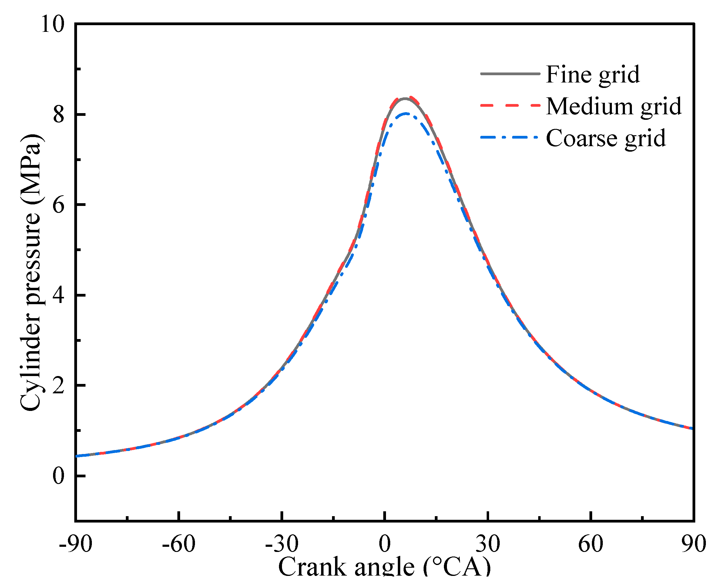
Based on the distribution of six nozzles in the bowl geometry of a four-stroke diesel engine, the 1/6 grid was generated. Thus, the 60° fan-shaped grid considered one nozzle. This paper adopted three types of meshes: coarse mesh, medium mesh, and fine mesh. When the piston was at top dead center (TDC), the three grid elements were 25,236, 201,582, and 1,452,418, respectively. All grids had very fine grids near the fuel injection path, injector nozzle, and piston clearance area to ensure that the model could accurately predict the rupture and evaporation of droplets. Figure 2 shows the cylinder pressures of three grids of pure diesel at full load. It can be seen that there was no obvious difference in the in-cylinder pressure curve between the fine grid and medium grid. The optimal medium grid was employed to predict the simulation process.

2.4. Model Validation

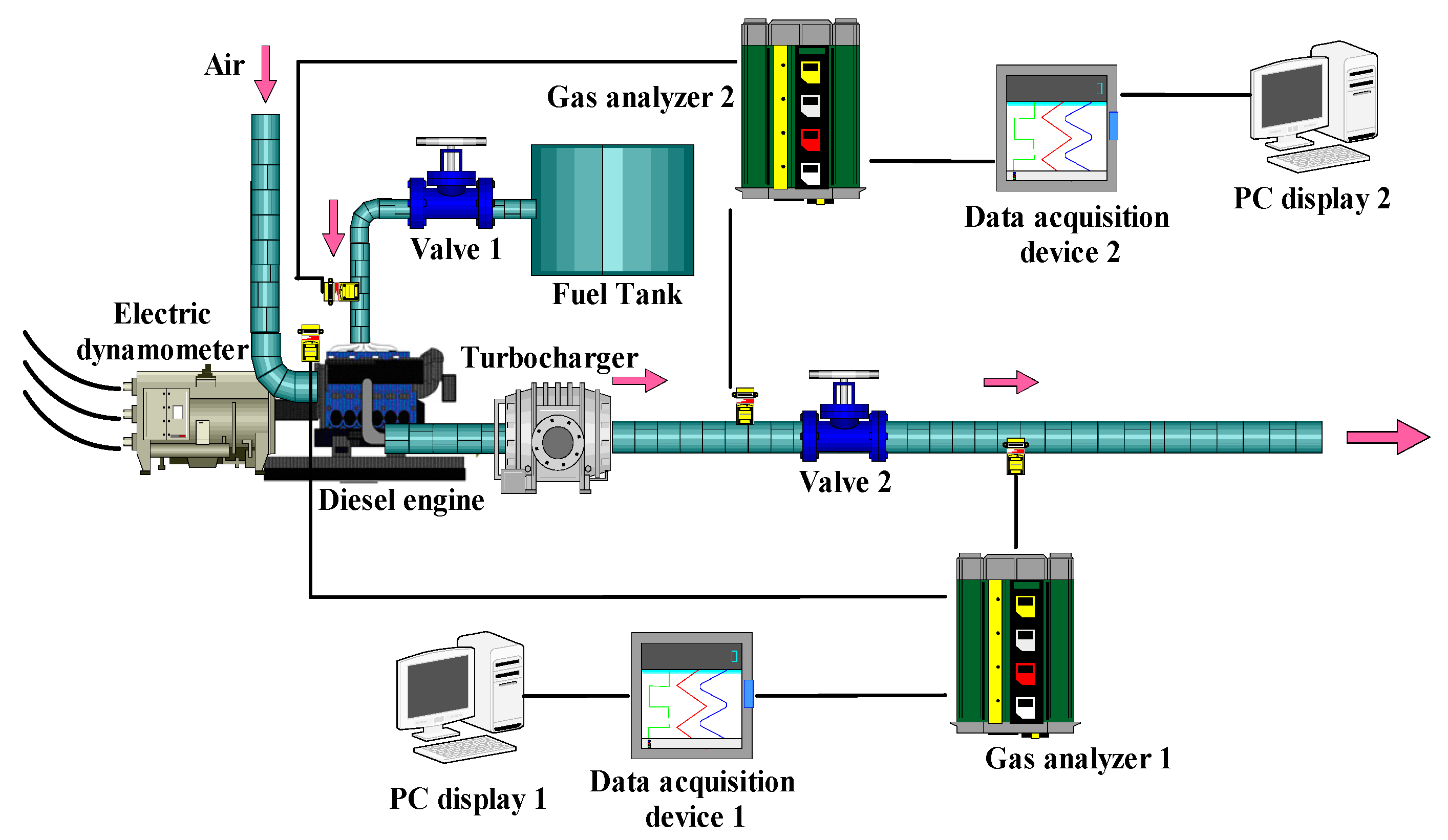
After the simulation model was established in the AVL Fire environment, the improved model was verified. Then, the experiments were carried out. In the paper, the schematic diagram of the experimental setup is shown in Figure 3. An exhaust gas analyzer (Horiba MEXA-1600) was used to measure the generated NOx with an error of 1%. A fuel consumption meter (FCMM-2) was used to measure BSFC. A combustion analyzer (DEWE-2010CA) was used to monitor the combustion of the diesel engine. Soot generated was measured using a smoke opacity meter (AVL Dismoke-4000). The fuel injection rate was measured using an EFS-IFR600 with a measurement error of 0.5%. The diesel engine load was measured using a hydraulic dynamometer. The ECU control system was used to control the electronically controlled diesel engine. In addition, temperature, flow, and pressure were measured using suitable sensors. Table 3 shows the list of measurements, measurement range, and accuracy.
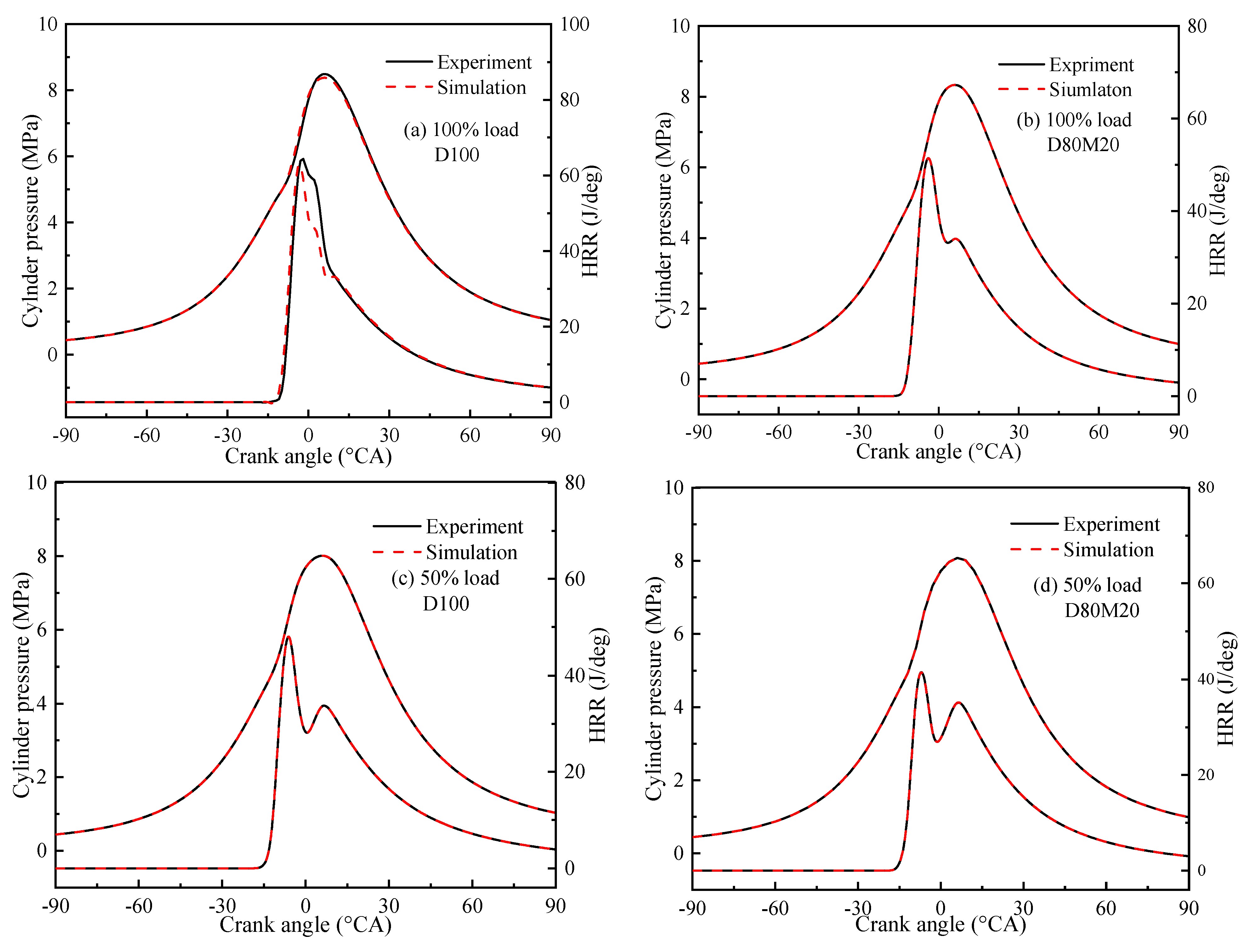
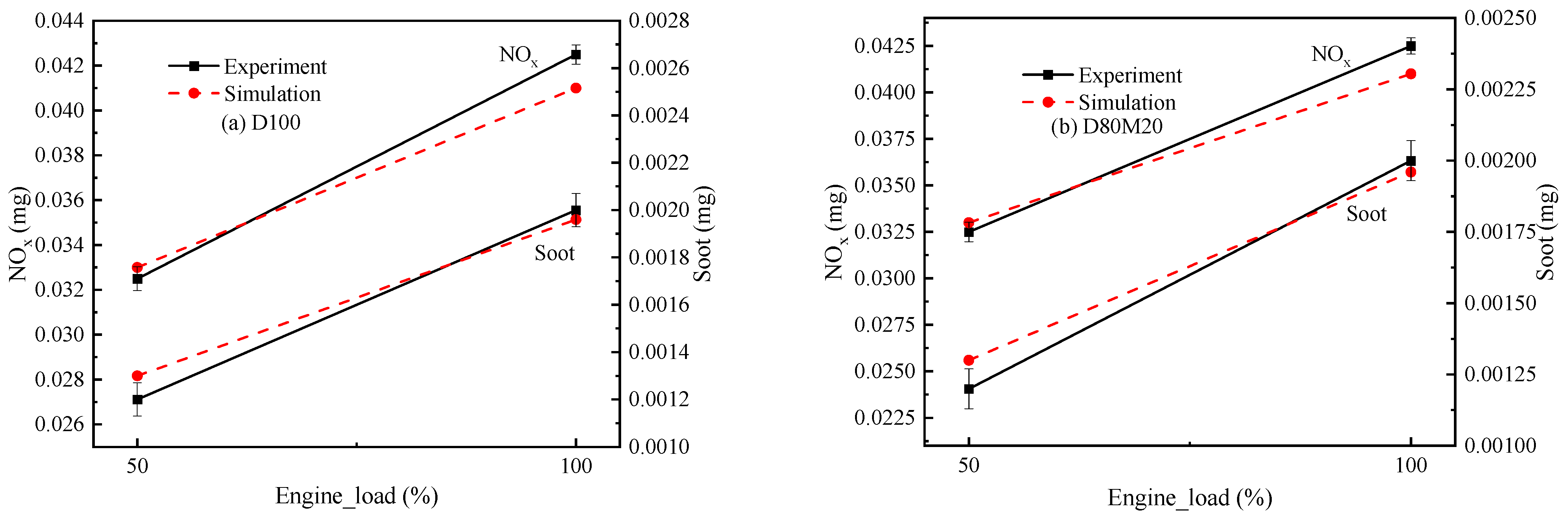
In order to verify the model, the experiments were carried out with a four-cylinder four-stroke engine fueled with diesel–methanol (D100, D80M20) at 100% and 50% loads, respectively. Figure 4a–d shows the cylinder pressure and heat release rate curves of D100 and D80M20 at 100% and 50% loads. The simulation results and heat release rate were consistent with the experimental results, and the error was less than 5%. In addition, Figure 5a,b shows the NOx and soot emissions at 100% and 50% load, respectively. Here too, the simulation was similar to the experiment. Thus, the established model could accurately predict the performance and combustion characteristics of the engine fueled with diesel–methanol.

3. Results and Discussion

The simulation experiment was carried out at 25% load, 50% load, 75% load, and 100% load, respectively. The effects of different proportions of diesel–methanol blended fuel on engine combustion and emission characteristics were studied in terms of cylinder pressure, cylinder temperature, heat release rate, brake specific fuel consumption, brake thermal efficiency, brake power, NOx emission, soot emission, and CO emission.

3.1. Combustion Characteristics

3.1.1. Cylinder Pressure

Figure 6a–d shows the effect of different diesel–methanol blend ratios on the engine cylinder pressure under different load conditions. The maximum combustion pressure of the diesel engine gradually increased as the methanol content in the mixed fuel increased. More specifically, compared with pure diesel, the cylinder pressures of D90M10, D80M20, and D70M30 increased by 0.78%, 1.21%, and 1.41%, respectively at 100% load. Methanol has a low cetane number and high latent heat of vaporization, which increases the ignition delay period in the cylinder, resulting in the increase in the maximum combustion pressure. Therefore, methanol increases the maximum combustion pressure of the cylinder. This is consistent with the experimental results of Chen et al. [25].

3.1.2. Heat Release Rate

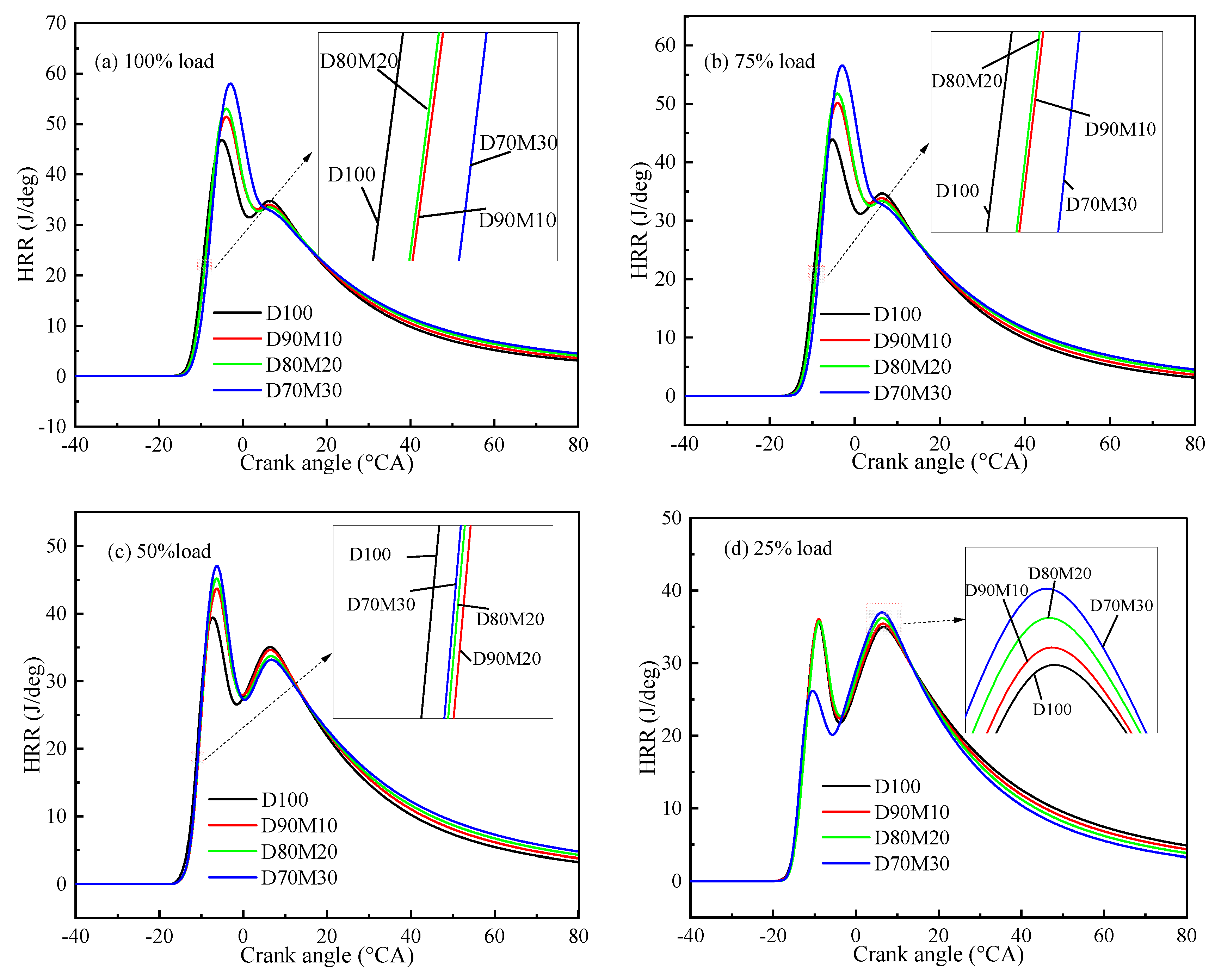
Figure 7a–d shows the heat release rate (HRR) curves of different proportions of diesel–methanol blended fuels under different load conditions. The peak values of engine heat release rate increased with the increase in methanol content in the mixed fuel. This is due to the prolonged ignition delay time caused by the high latent heat of evaporation. More fuel is provided for the vaporization and mixing of diesel–methanol so that the air and fuel can be mixed better. In addition, the addition of oxygenated fuel increases the kinetic combustion stage in the diffusion combustion process, resulting in the increase in HRR and the improvement of combustion efficiency.

3.1.3. Cylinder Temperature

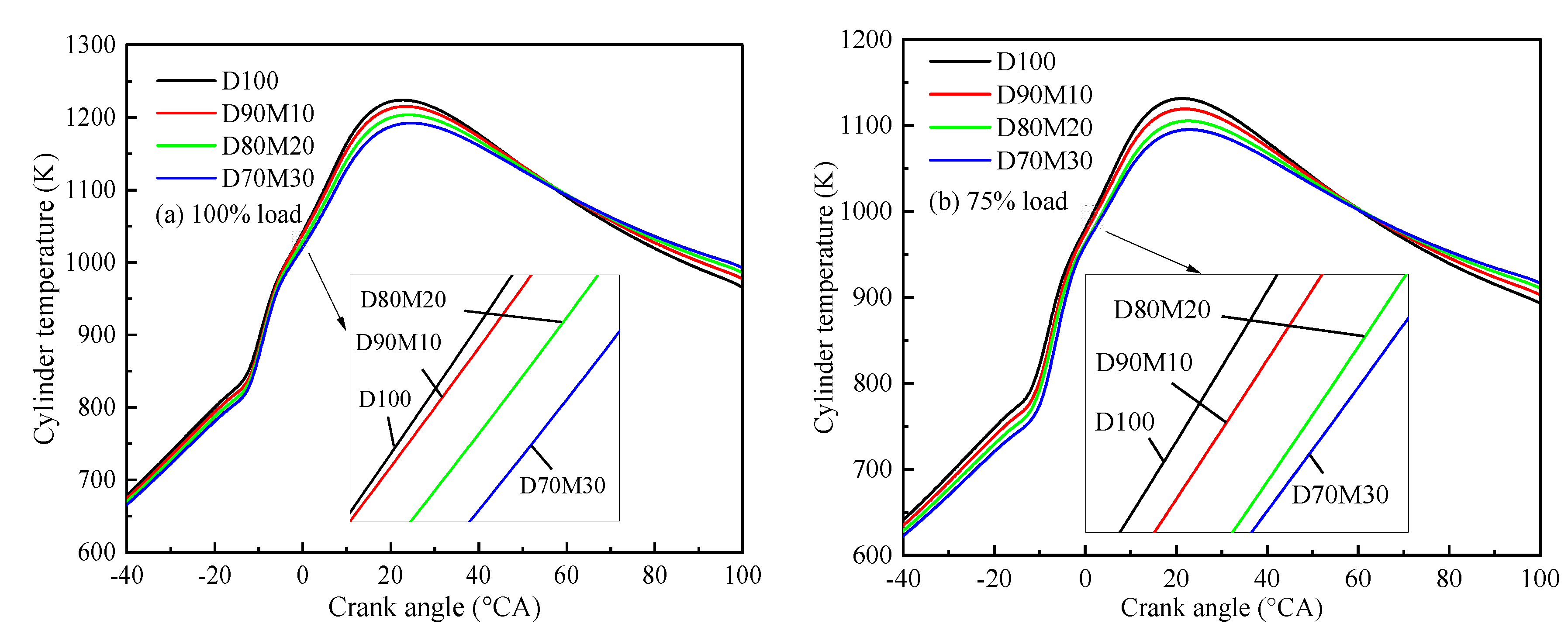
Figure 8a–d shows the temperature curves of different proportions of diesel–methanol blended fuel under different load conditions. It can be seen that the maximum cylinder temperature gradually decreased as the methanol content in the mixed fuel increased. More specifically, at 100% load, the maximum cylinder temperatures of D100, D90M10, D80M20, and D70M30 were 1224.5 K, 1215.9 K, 1204.5 K, and 1192.9 K, respectively. This is because methanol has a low calorific value. Thus, the calorific value of the mixed fuel decreased, and the heat was reduced in the combustion process with the increase in methanol content in the mixed fuel. The study of Zhang et al. [26,27] provided similar conclusions.
Figure 9 shows the temperature distribution field in the cylinder at 100% load. The combustion of pure diesel produced more local high-temperature zones than diesel–methanol mixed fuel. This was due to the calorific value and micro-explosion of methanol. With the increase in methanol content in the blended fuel, the micro-explosion was violent and the calorific value of blended fuel was reduced. Thus, a local high-temperature zone can be reduced with an increase in methanol content in the blended fuel. In addition, methanol has a higher latent heat of vaporization, and the increase in methanol content reduces the combustion temperature of the mixed fuel.

3.2. Economic Characteristics

3.2.1. Brake Specific Fuel Consumption

Brake specific fuel consumption (BSFC) is an important parameter to measure the economic characteristics of the engine [28]. The lower the fuel consumption, the better the economy of the engine [29]. Figure 10a shows the BSFCs of different proportions of diesel–methanol blended fuel under different load conditions. It can be seen that the fuel consumption of diesel engines increased gradually with the increase in methanol content in mixed fuel. For example, the BSFC was 301.89 g/(kW·h) when the diesel engine fuel was pure diesel at 25% load. Compared with the BSFC of diesel, the BSFCs of the maximum cylinder temperatures of D100, D90M10, D80M20, and D70M30 were 305.37 g/(kW·h), 307.96 g/(kW·h), and 312.66 g/(kW·h) respectively. This is because the calorific value of methanol (20.1 MJ/kg) is much lower than that of diesel (42.5 MJ/kg). The increase in methanol content in the mixed fuel reduces the total calorific value of the mixed fuel, resulting in an increase in BSFC. Similarly, this result was consistent with that of Hasan et al. [30].

3.2.2. Brake Thermal Efficiency

Brake thermal efficiency (BTE) is the ratio of energy generated by fuel combustion in the engine into active work [31]. Figure 10b shows the brake thermal efficiencies of diesel–methanol blended fuel with different proportions under different load conditions. The BTE increased with the increase in methanol content in the mixed fuel. The increase in methanol content in diesel–methanol blended fuel improves the spray characteristics and the oxygen in methanol makes the fuel combustion more efficient, thus improving the BTE of the engine.

3.2.3. Brake Power

Figure 10c shows the brake power of different proportions of diesel–methanol blended fuel under different load conditions. With the increase in methanol content in the mixed fuel, the brake power gradually decreased. In addition, the higher the methanol content in the mixed fuel, the more significant the decrease in brake power. Compared with pure diesel, the power of D90M10, D80M20, and D70M30 blended fuel decreased by 2.76%, 5.04%, and 8.08%, respectively. This is because the calorific value of the mixed fuel is lower than that of pure diesel, resulting in lower power than diesel during combustion. Some researchers have also shown that the power performance of the engine decreases with the increase in the methanol ratio [32,33].

3.3. Emission Characteristics

3.3.1. NOx Emissions

Figure 11a–d shows the NOx emission of diesel–methanol blended fuel with different proportions under different load conditions. NOx emission increased with the increase in engine load. The increase in engine load will lead to the increase in cylinder temperature. High temperature promotes the formation of NOx. In addition, NOx emission increases with the increase in methanol content in the mixed fuel, which is due to the improved combustion caused by the oxygen content in the methanol. Similarly, the cetane number of diesel–methanol blended fuel is lower than that of pure diesel, resulting in the increase in ignition delay period and premixed combustion. Thus, more NOx will be produced. Liu et al. [34] reached a similar conclusion.

3.3.2. Soot Emissions

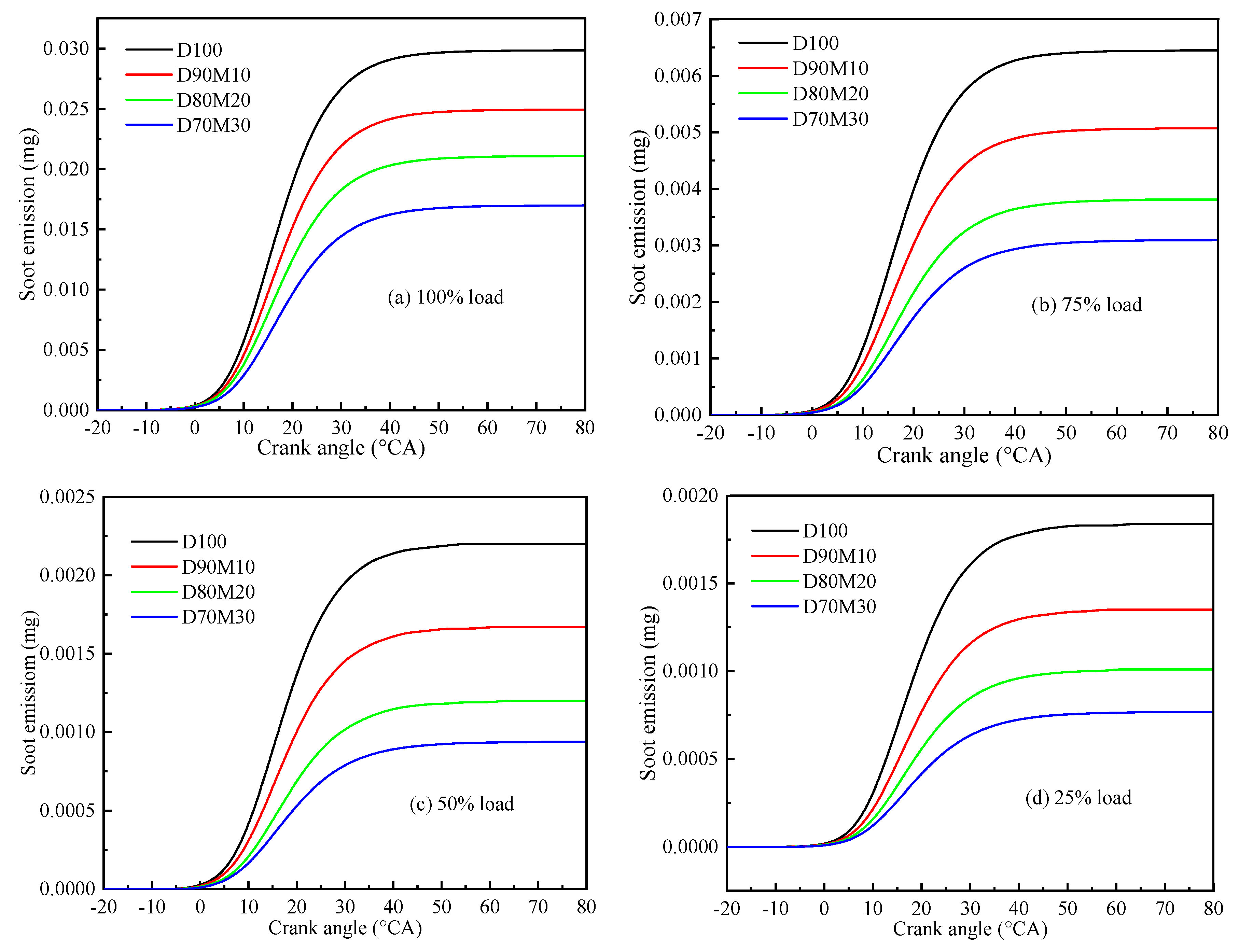
Figure 12a–d shows the soot emissions of diesel–methanol blended fuel with different proportions under different load conditions. The soot emission increased gradually with the increase in engine load. This is due to the poor oxygen when the fuel mass increases, and a large amount of soot is formed in the high-temperature oxygen-poor area. However, with the increase in methanol content in the mixed fuel, the soot emission decreased gradually. For example, at 100% load, when the proportion of methanol in the mixed fuel increased to 10%, 20%, and 30%, the soot emission was reduced by 16.45%, 29.35%, and 43.05%, respectively. This is because the high oxygen content of methanol improved the cylinder combustion. The greater the amount of methanol added, the better the oxidation effect of soot.
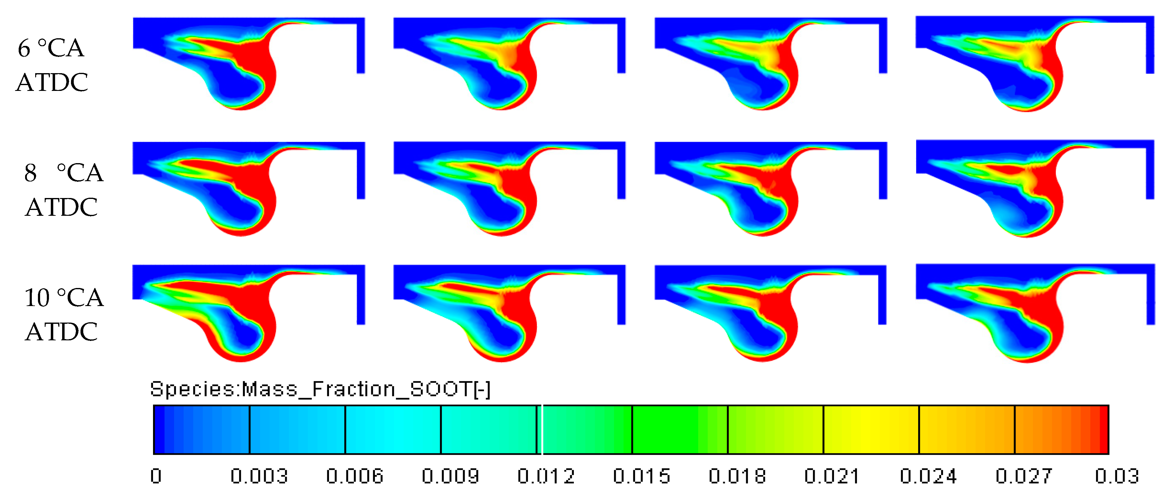
In addition, Figure 13 shows the soot distribution field in the cylinder. The results show that burning diesel–methanol blended fuel reduced the spot distribution in the cylinder. Therefore, burning diesel–methanol blended fuel can significantly reduce soot emissions. Zhang et al. [35] reached a similar conclusion.

3.3.3. CO Emissions

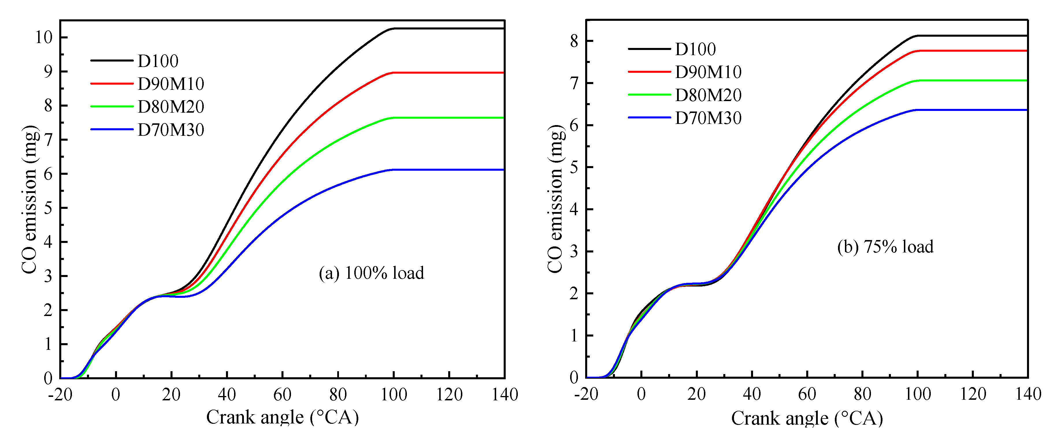
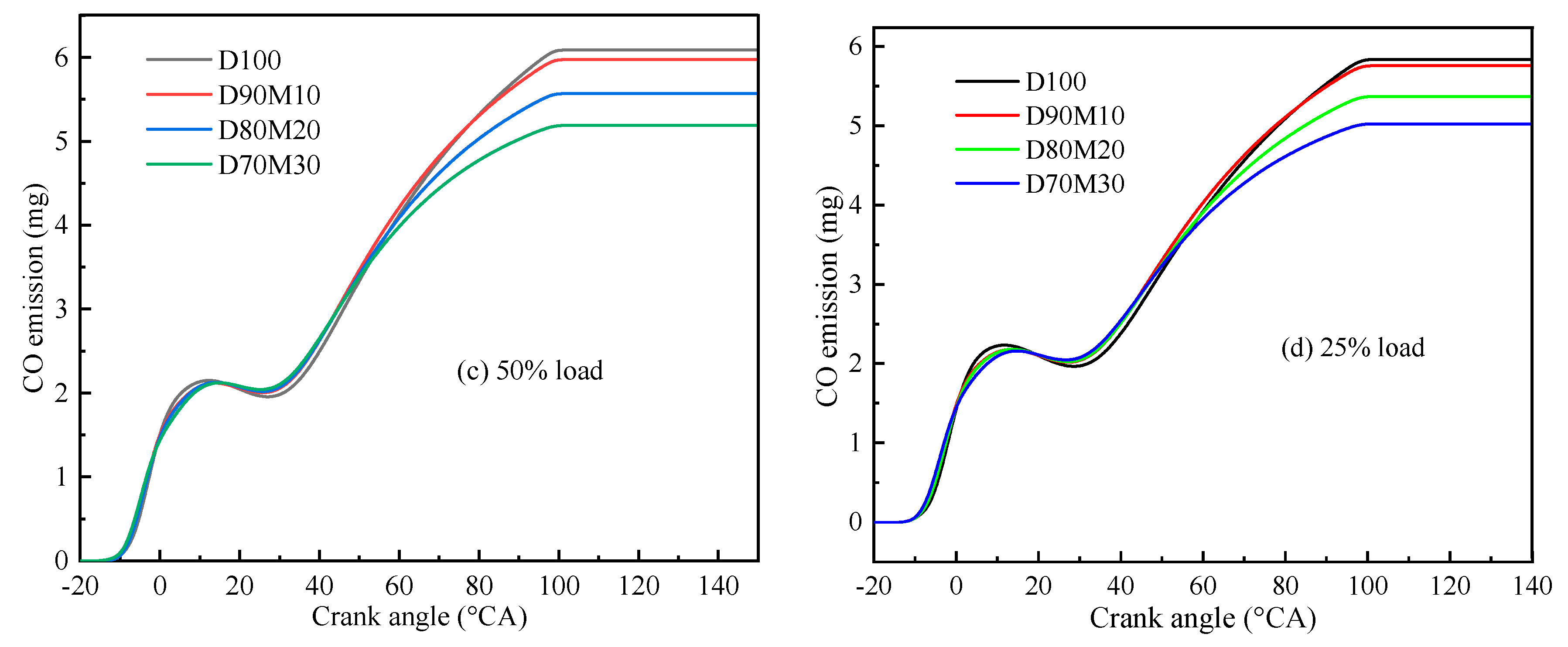
Figure 14a–d shows the CO emissions of diesel–methanol blended fuel with different proportions under different load conditions. CO emission gradually increased with the increase in engine load. However, CO emission gradually decreased as the methanol content in the mixed fuel increased. As the engine load increased, the oxygen in the cylinder became leaner, and the fuel could not be completely burned, resulting in higher CO emission. However, the addition of methanol increased the oxygen content of the mixed fuel and improved the combustion in the cylinder. Thus, the CO emission was reduced. This was consistent with the findings of Wu et al. [36] and Sayin et al. [37].

4. Conclusions

With the worsening of the global energy crisis [38,39,40,41,42,43,44,45,46,47] and environmental problems [48,49,50,51,52,53,54,55,56,57], the development of diesel engines is also facing great challenges. Today, the search for clean energy to reduce the emission of harmful gases has become a research hotspot [58]. In this paper, a three-dimensional CFD model was established in an AVL-Fire environment and verified by the experimental results. In addition, the effects of different diesel–methanol blended fuels on the combustion and emission characteristics of diesel engines were studied in term of cylinder pressure, heat release rate, cylinder temperature, brake specific fuel consumption, brake thermal efficiency, brake power, soot, NOx, and CO. Based on the above analysis, D80M20 is the optimal diesel–methanol blended fuel. The main conclusions are as follows:
(1)
The proportion of methanol in the diesel–methanol mixture fuel significantly influenced the engine’s combustion characteristics. More specifically, the addition of methanol improved the combustion characteristics of diesel engines. Compared with pure diesel, as the proportion of methanol increased, the combustion speed of the fuel was accelerated, and the combustion time was shortened. As a result, the cylinder pressure and HRR increased; on the contrary, the cylinder temperature decreased.
(2)
The proportion of methanol in the diesel–methanol mixture fuel significantly influenced the engine’s economic characteristics. Compared with pure diesel, diesel–methanol blended fuel reduced the economic cost of running diesel engines. The calorific value of methanol is lower than that of diesel. With the increase in methanol content, the calorific value of mixed fuel decreased, which increased fuel consumption and reduced power.
(3)
The proportion of methanol in the diesel–methanol mixture fuel significantly influenced the engine’s emission characteristics. The addition of methanol can reduce soot and CO emissions. The high oxygen content of methanol causes the fuel to burn completely, thus reducing the soot and CO emissions. However, with the increase in methanol content, NOx emission increased.
In conclusion, adding methanol can improve the combustion and emission characteristics of the engine. In order to further study the combustion and emission characteristics of diesel-methanol engines, future work will use the full model of the engine for more in-depth research to obtain more accurate results.

Author Contributions

Conceptualization, W.L. and Z.Z.; software, S.C., J.T., J.L. and Z.Z.; formal analysis, J.T., W.L. and Z.Z.; investigation, S.C. and W.L.; resources, W.L. and Z.Z.; writing—original draft preparation, S.C. and W.L.; writing—review and editing, S.C., J.T., J.L., W.L. and Z.Z.; supervision, W.L. and Z.Z.; funding acquisition, Z.Z.. All authors have read and agreed to the published version of the manuscript.

Funding

This research is supported by the Guangxi University of Science and Technology Doctoral Fund under the research grants of 20Z22, 20S04 and 21Z34; the work is supported by the Natural Science Foundation of Guangxi under the research grants of 2018GXNSFAA281267 and 2018 GXNSFAA 294072.

Data Availability Statement

All data used to support the findings of this study are included within the article.

Conflicts of Interest

The authors declare that they have no conflict of interest regarding the publication of this paper.

References

  1. Zhang, Z.; Jiaqiang, E.; Chen, J.; Zhao, X.; Zhang, B.; Deng, Y.; Peng, Q.; Yin, Z. Effects of boiling heat transfer on the performance enhancement of a medium speed diesel engine fueled with diesel and rapeseed methyl ester. Appl. Therm. Eng. 2020, 169, 114984. [Google Scholar] [CrossRef]
  2. Zhang, Z.; Jiaqiang, E.; Chen, J.; Zhu, H.; Zhao, X.; Han, D.; Zuo, W.; Peng, Q.; Gong, J.; Yin, Z. Effects of low-level water addition on spray, combustion and emission characteristics of a medium speed diesel engine fueled with biodiesel fuel. Fuel 2019, 239, 245–262. [Google Scholar] [CrossRef]
  3. Lu, Y.; Jiang, Z.; Geng, N.; Jiang, S.; Xie, X. Appointment Window Scheduling with Wait-Dependent Abandonment for Elective Inpatient Admission. Int. J. Prod. Res. 2021, 1977407. [Google Scholar] [CrossRef]
  4. Zhao, D.; Ji, C.; Li, X.; Li, S. Mitigation of premixed flame-sustained thermoacoustic oscillations using an electrical heater. Int. J. Heat Mass Transf. 2015, 86, 309–318. [Google Scholar] [CrossRef]
  5. Jiaqiang, E.; Liu, M.; Deng, Y.; Zhu, H.; Gong, J. Influence analysis of monolith structure on regeneration temperature in the process of microwave regeneration in the diesel particulate filter. Can. J. Chem. Eng. 2015, 94, 168–174. [Google Scholar]
  6. Rahman, S.M.A.; Fattah, I.M.R.; Ong, H.C.; Zamri, M. State-of-the-Art of Strategies to Reduce Exhaust Emissions from Diesel Engine Vehicles. Energies 2021, 14, 24. [Google Scholar] [CrossRef]
  7. Cai, T.; Zhao, D. Effects of fuel composition and wall thermal conductivity on thermal and NOx emission performances of an ammonia/hydrogen-oxygen micro-power system. Fuel Process. Technol. 2020, 209, 106527. [Google Scholar] [CrossRef]
  8. Zhang, Z.; Ye, J.; Tan, D.; Feng, Z.; Luo, J.; Tan, Y.; Huang, Y. The effects of Fe2O3 based DOC and SCR catalyst on the combustion and emission characteristics of a diesel engine fueled with biodiesel. Fuel 2021, 290, 120039. [Google Scholar] [CrossRef]
  9. Serrano, J.R.; Arnau, F.J.; Martín, J.; Auñón, Á. Development of a Variable Valve Actuation Control to Improve Diesel Oxidation Catalyst Efficiency and Emissions in a Light Duty Diesel Engine. Energies 2020, 13, 4561. [Google Scholar] [CrossRef]
  10. Muhssen, H.S.; Masuri, S.U.; Bin Sahari, B.; Hairuddin, A.A. Design improvement of compressed natural gas (CNG)-Air mixer for diesel dual-fuel engines using computational fluid dynamics. Energy 2021, 216, 118957. [Google Scholar] [CrossRef]
  11. Wei, J.; Yin, Z.; Wang, C.; Lv, G.; Zhuang, Y.; Li, X.; Wu, H. Impact of aluminium oxide nanoparticles as an additive in diesel-methanol blends on a modern DI diesel engine. Appl. Therm. Eng. 2020, 185, 116372. [Google Scholar] [CrossRef]
  12. Li, Y.; Wang, S.; Xiongbo, D.; Liu, S.; Liu, J.; Hu, S. Multi-objective energy management for Atkinson cycle engine and series hybrid electric vehicle based on evolutionary NSGA-II algorithm using digital twins. Energy Convers. Manag. 2021, 230, 113788. [Google Scholar] [CrossRef]
  13. Ning, L.; Duan, Q.; Zhanming, C.; Kou, H.; Liu, B.; Yang, B.; Zeng, K. A comparative study on the combustion and emissions of a non-road common rail diesel engine fueled with primary alcohol fuels (methanol, ethanol, and n-butanol)/diesel dual fuel. Fuel 2020, 266, 117034. [Google Scholar] [CrossRef]
  14. Debnath, B.; Saha, U.; Sahoo, N.A. Comprehensive Review on the Application of Emulsions as an Alternative Fuel for Diesel Engines. Renew. Sustain. Energy Rev. 2014, 42, 196–211. [Google Scholar] [CrossRef]
  15. Zhanming, C.; He, J.; Chen, H.; Geng, L.; Zhang, P. Comparative study on the combustion and emissions of dual-fuel common rail engines fueled with diesel/methanol, diesel/ethanol, and diesel/n-butanol. Fuel 2021, 304, 121360. [Google Scholar]
  16. Fan, C.; Wei, J.; Huang, H.; Pan, M.; Fu, Z. Chemical feature of the soot emissions from a diesel engine fueled with methanol-diesel blends. Fuel 2021, 297, 120739. [Google Scholar] [CrossRef]
  17. Li, Z.; Wang, Y.; Yin, Z.; Gao, Z.; Wang, Y.; Zhen, X. Parametric study of a single-channel diesel/methanol dual-fuel injector on a diesel engine fueled with directly injected methanol and pilot diesel. Fuel 2021, 302, 121156. [Google Scholar] [CrossRef]
  18. Gao, Z.; Wu, S.; Luo, J.; Zhang, B.; Zhang, H.; Xiao, R. Optimize the co-solvent for methanol in diesel with group of oxygen-containing reagents: Molecular structure and intermolecular forces analysis. Fuel Process. Technol. 2021, 222, 106980. [Google Scholar] [CrossRef]
  19. Pan, K.L.; Chiu, M. Droplet combustion of blended fuels with alcohol and biodiesel/diesel in microgravity condition. Fuel 2013, 113, 757–765. [Google Scholar] [CrossRef]
  20. Li, G.; Zhang, C.; Li, Y. Effects of diesel injection parameters on the rapid combustion and emissions of an HD common-rail diesel engine fueled with diesel-methanol dual-fuel. Appl. Therm. Eng. 2016, 108, 1214–1225. [Google Scholar] [CrossRef]
  21. Panda, K.; Ramesh, A. Diesel injection strategies for reducing emissions and enhancing the performance of a methanol based dual fuel stationary engine. Fuel 2021, 289, 119809. [Google Scholar] [CrossRef]
  22. Liang, J.; Zhang, Q.; Chen, Z.; Zheng, Z.; Yang, C.; Ma, Q. The combustion and emission characteristics of diesel-ethanol blends with THF as cosolvents in a diesel engine operating with EGR. Fuel 2021, 298, 120843. [Google Scholar] [CrossRef]
  23. Liu, T.; E., J.; Yang, W.; Hui, A.; Cai, H. Development of a skeletal mechanism for biodiesel blend surrogates with varying fatty acid methyl esters proportion. Appl. Energy 2016, 162, 278–288. [Google Scholar] [CrossRef]
  24. Luo, J.; Liu, Z.; Wang, J.; Chen, H.; Zhang, Z.; Qin, B.; Cui, S. Effects of Different Injection Strategies on Combustion and Emission Characteristics of Diesel Engine Fueled with Dual Fuel. Processes 2021, 9, 1300. [Google Scholar] [CrossRef]
  25. Chen, H.; Su, X.; He, J.; Xie, B. Investigation on combustion and emission characteristics of a common rail diesel engine fueled with diesel/n-pentanol/methanol blends. Energy 2018, 167, 297–311. [Google Scholar] [CrossRef]
  26. Zhang, Z.; Tian, J.; Li, J.; Ji, H.; Tan, D.; Luo, J.; Jiang, Y.; Yang, D.; Cui, S. Effects of Different Mixture Ratios of Methanol-Diesel on the Performance Enhancement and Emission Reduction for a Diesel Engine. Processes 2021, 9, 1366. [Google Scholar] [CrossRef]
  27. Zhang, Z.; Li, J.; Tian, J.; Xie, G.; Tan, D.; Qin, B.; Huang, Y.; Cui, S. Effects of Different Diesel-Ethanol Dual Fuel Ratio on Performance and Emission Characteristics of Diesel Engine. Processes 2021, 9, 1135. [Google Scholar] [CrossRef]
  28. Devarajan, Y.; Munuswamy, D.; Nagappan, B.; Subbiah, G. Experimental assessment of performance and exhaust emission characteristics of a diesel engine fuelled with Punnai biodiesel/butanol fuel blends. Pet. Sci. 2019, 16, 1471–1478. [Google Scholar] [CrossRef] [Green Version]
  29. Justin Abraham Baby, S.; Suresh Babu, S.; Devarajan, Y. Performance study of neat biodiesel-gas fuelled diesel engine. Int. J. Ambient. Energy 2018, 42, 269–273. [Google Scholar] [CrossRef]
  30. Hasan, A.; Osman, A.; Al-Muhtaseb, A.; Al-Rawashdeh, H.; Abu, J.A.; Ahmad, R.; Behiri, M.; Deka, T.J.; Rooney, D. An experimental study of engine characteristics and tailpipe emissions from modern DI diesel engine fuelled with methanol/diesel blends. Fuel Process Technol. 2021, 220, 106901. [Google Scholar] [CrossRef]
  31. Tan, D.; Chen, Z.; Li, J.; Luo, J.; Yang, D.; Cui, S.; Zhang, Z. Effects of Swirl and Boiling Heat Transfer on the Performance Enhancement and Emission Reduction for a Medium Diesel Engine Fueled with Biodiesel. Processes 2021, 9, 568. [Google Scholar] [CrossRef]
  32. Han, D.; Sun, S. Study on Performance of Diesel Engine Supplied with Methanol-Diesel Blended Fuel. Adv. Mat. Res. 2011, 418–420, 133–138. [Google Scholar] [CrossRef]
  33. Chen, Z.; Liu, J.; Han, Z.; Du, B.; Liu, Y.; Lee, C. Study on performance and emissions of a passenger-car diesel engine fueled with butanol–diesel blends. Energy 2013, 55, 638–646. [Google Scholar] [CrossRef]
  34. Liu, T.; E, J.; Yang, W.M.; Deng, Y.; An, H.; Zhang, Z.; Pham, M. Investigation on the applicability for adjusting reaction rates of the optimized biodiesel skeletal mechanism. Energy 2018, 150, 1031–1038. [Google Scholar] [CrossRef]
  35. Zhang, Z.H.; Cheung, C.S.; Yao, C. Influence of fumigation methanol on the combustion and particulate emissions of a diesel engine. Fuel 2013, 111, 442–448. [Google Scholar] [CrossRef]
  36. Wu, G.; Wu, D.; Li, Y.; Meng, L. Effect of Acetone-n-Butanol-Ethanol (ABE) as an Oxygenate on Combustion, Performance, and Emission Characteristics of a Spark Ignition Engine. J. Chem. 2020, 2020, 7468651. [Google Scholar] [CrossRef] [Green Version]
  37. Sayin, C. Engine performance and exhaust gas emissions of methanol and ethanol–diesel blends. Fuel 2010, 89, 3410–3415. [Google Scholar] [CrossRef]
  38. Zuo, H.; Tan, J.; Wei, K.; Huang, Z.; Zhong, D.; Xie, F. Effects of different poses and wind speeds on wind-induced vibration characteristics of a dish solar concentrator system. Renew. Energy 2021, 168, 1308–1326. [Google Scholar] [CrossRef]
  39. Zuo, H.; Liu, G.; Jiaqiang, E.; Zuo, W.; Wei, K.; Hu, W.; Tan, J.; Zhong, D. Catastrophic analysis on the stability of a large dish solar thermal power generation system with wind-induced vibration. Sol. Energy 2019, 183, 40–49. [Google Scholar] [CrossRef]
  40. Hu, L.; Hu, X.; Che, Y.; Feng, F.; Lin, X.; Zhang, Z. Reliable state of charge estimation of battery packs using fuzzy adaptive federated filtering. Appl. Energy 2020, 262, 114569. [Google Scholar] [CrossRef]
  41. Zhang, F.; Liao, G.; E, J.; Chen, J.; Leng, E. Comparative study on the thermodynamic and economic performance of novel absorption power cycles driven by the waste heat from a supercritical CO2 cycle. Energy Convers. Manag. 2021, 228, 113671. [Google Scholar] [CrossRef]
  42. Zuo, H.; Zhang, B.; Huang, Z.; Wei, K.; Tan, J. Effect analysis on SOC values of the power lithium manganate battery during discharging process and its intelligent estimation. Energy 2022, 238, 121854. [Google Scholar] [CrossRef]
  43. E, J.; Zhang, B.; Zeng, Y.; Wen, M.; Huang, Z.; Wei, K.; Chen, J.; Zhu, H.; Deng, Y. Effects analysis on active equalization control of lithium-ion batteries based on intelligent estimation of the state-of-charge. Energy 2022, 238, 121822. [Google Scholar] [CrossRef]
  44. Cai, T.; Sun, Y.; Zhao, D. Enhancing heat transfer performance analyses of a hydrogen-fueled meso-combustor with staggered bluff-bodies. Fuel Process. Technol. 2021, 218, 106867. [Google Scholar] [CrossRef]
  45. Cai, T.; Zhao, D. Mitigating NOx emissions from an ammonia-fueled micro-power system with a perforated plate implemented. J. Hazard. Mater. 2021, 401, 123848. [Google Scholar] [CrossRef] [PubMed]
  46. Cai, T.; Becker, S.M.; Cao, F.; Wang, B.; Tang, A.K.; Fu, J.Q.; Han, L.; Sun, Y.Z.; Zhao, D. NOx emission performance assessment on a perforated plate-implemented premixed ammonia-oxygen micro-combustion system. Chem. Eng. J. 2021, 417, 128033. [Google Scholar] [CrossRef]
  47. Cai, T.; Zhao, D.; Wang, B.; Li, J.W.; Guan, Y.H. NOx emission and thermal performances studies on premixed ammonia-oxygen combustion in a CO2-free micro-planar combustor. Fuel 2020, 280, 118554. [Google Scholar] [CrossRef]
  48. Ma, Y.; Liu, C.; E, J.; Mao, X.; Yu, Z. Research on modeling and parameter sensitivity of flow and heat transfer process in typical rectangular microchannels: From a data-driven perspective. Int. J. Therm. Sci. 2022, 172, 107356. [Google Scholar] [CrossRef]
  49. E, J.; Pham, M.; Zhao, D.; Deng, Y.; Le, D.; Zuo, W.; Zhu, H.; Liu, T.; Peng, Q.; Zhang, Z. Effect of different technologies on combustion and emissions of the diesel engine fueled with biodiesel: A review. Renew. Sustain. Energy Rev. 2017, 80, 620–647. [Google Scholar] [CrossRef]
  50. Zhang, B.; Zuo, H.; Huang, Z.; Tan, J.; Zuo, Q. Endpoint forecast of different diesel-biodiesel soot filtration process in diesel particulate filters considering ash deposition. Fuel 2020, 272, 117678. [Google Scholar] [CrossRef]
  51. Zhang, Z.; E, J.; Deng, Y.; Pham, M.; Zuo, W.; Peng, Q.; Yin, Z. Effects of fatty acid methyl esters proportion on combustion and emission characteristics of a biodiesel fueled marine diesel engine. Energy Convers. Manag. 2018, 159, 244–253. [Google Scholar] [CrossRef]
  52. E, J.; Zhao, M.; Zuo, Q.; Zhang, B.; Zhang, Z.; Peng, Q.; Han, D.; Zhao, X.; Deng, Y. Effects analysis on diesel soot continuous regeneration performance of a rotary microwave-assisted regeneration diesel particulate filter. Fuel 2020, 260, 116353. [Google Scholar] [CrossRef]
  53. Feng, C.; Deng, Y.; Chen, L.; Han, W.; E, J.; Wei, K.; Han, D.; Zhang, B. Hydrocarbon emission control of a hydrocarbon adsorber and converter under cold start of the gasoline engine. Energy 2022, 239, 122138. [Google Scholar] [CrossRef]
  54. Chen, L.; Deng, Y.; Feng, C.; Han, W.; E, J.; Wang, C.; Han, D.; Zhang, B. Effects of zeolite molecular sieve on the hydrocarbon adsorbent performance of gasoline engine of during cold start. Fuel 2022, 310, 122427. [Google Scholar] [CrossRef]
  55. E, J.; Luo, J.; Han, D.; Tan, Y.; Feng, C.; Deng, Y. Effects of different catalysts on light-off temperature of volatile organic components in the rotary diesel particulate filter during the regeneration. Fuel 2022, 310, 122451. [Google Scholar] [CrossRef]
  56. Li, W.; Ji, J.; Huang, L.; Guo, Z. Global dynamics of a controlled discontinuous diffusive SIR epidemic system. Appl. Math. Lett. 2021, 121, 107420. [Google Scholar] [CrossRef]
  57. Zhao, D.; Guan, Y.; Reinecke, A. Characterizing hydrogen-fuelled pulsating combustion on thermodynamic properties of a combustor. Commun. Phys. 2019, 2, 1234567890. [Google Scholar] [CrossRef] [Green Version]
  58. E, J.; Zhang, Z.; Tu, Z.; Wei, Z.; Hu, W.; Han, D.; Jin, Y. Effect analysis on flow and boiling heat transfer performance of cooling water-jacket of bearing in the gasoline engine turbocharger. Appl. Therm. Eng. 2018, 130, 754–766. [Google Scholar] [CrossRef]
Figure 1. Three dimensional CFD simulation model of the cylinder.
Processes 09 01944 g001
Figure 2. The cylinder pressure comparison of grid independent test.
Processes 09 01944 g002
Figure 3. Schematic diagram of experimental device.
Processes 09 01944 g003
Figure 4. Comparison of cylinder pressure and HRR of different proportions of diesel–methanol blended fuel under different load conditions. (a) D100 at 100% load, (b) D80M20 at 100% load, (c) D100 at 50% load, (d) D80M20 at 50% load.
Processes 09 01944 g004
Figure 5. Engine validation results for NOx and soot emissions. (a) D100, (b) D80M20.
Processes 09 01944 g005
Figure 6. Cylinder pressure curves of different proportions of diesel–methanol blended fuel under different load conditions. (a) at 100% load, (b) at 75% load, (c) at 50% load, (d) at 25% load.
Processes 09 01944 g006
Figure 7. Heat release rate curves of different proportions of diesel–methanol blended fuel under different load conditions. (a) at 100% load, (b) at 75% load, (c) at 50% load, (d) at 25% load.
Processes 09 01944 g007
Figure 8. Heat release rate curves of different proportions of diesel–methanol blended fuel under different load conditions. (a) at 100% load, (b) at 75% load, (c) at 50% load, (d) at 25% load.
Processes 09 01944 g008aProcesses 09 01944 g008b
Figure 9. The distribution field of the temperature in cylinder.
Processes 09 01944 g009
Figure 10. BSFC, BTE. and brake power of different proportions of diesel–methanol blended fuel under different load conditions. (a) BSFC, (b) BTE, (c) Brake power.
Processes 09 01944 g010
Figure 11. NOx emission curves of different proportions of diesel–methanol blended fuel under different load conditions. (a) at 100% load, (b) at 75% load, (c) at 50% load, (d) at 25% load.
Processes 09 01944 g011
Figure 12. Soot emission curves of different proportions of diesel–methanol blended fuel under different load conditions. (a) at 100% load, (b) at 75% load, (c) at 50% load, (d) at 25% load.
Processes 09 01944 g012
Figure 13. The soot distribution field in the cylinder.
Processes 09 01944 g013aProcesses 09 01944 g013b
Figure 14. CO emission curves of different proportions of diesel–methanol blended fuel under different load conditions. (a) at 100% load, (b) at 75% load, (c) at 50% load, (d) at 25% load.
Processes 09 01944 g014aProcesses 09 01944 g014b
Table 1. Key parameters of the diesel engine.
Performance IndexUnitValue
Cylinder diametermm90
Boremm98
Number of cylinders-4
Rate speedr/min1800
Peak pressureMPa12
Rated powerkW220
Mean effective pressureMPa2.05
Compression ratio-14:1
Table 2. Main physical and chemical properties of the fuel.
PropertiesD100MethanolD90M10D80M20D70M30
Latent heat of gasification (KJ/kg)2601162350.2440.4530.6
Autoignition temperature (°C)250463271.3292.6313.9
Density (kg/m3) at 20 °C835792830.7826.4822.1
Low calorific value (MJ/kg)42.520.140.2638.0235.78
Cetane number513.846.2841.5636.84
Stoichiometric air fuel ratio14.36.513.5212.7411.96
Kinematic viscosity (40 °C) (mm2/s)2.720.582.5062.2922.078
Table 3. Lists of measurements, the measuring range, and accuracy.
MeasurementsMeasuring RangeAccuracyUncertainty (%)
Cylinder pressure1–25 MPa±10 kPa±0.5
Exhaust gas temperature0–1000 °C±1 °C±0.25
Brake power-0.03 kW±0.03
NOx emission0–5000 ppm±10 ppm±0.53
Soot emission0–9 FSN±0.1 FSN±2.8
BSFC-±5 g/kW h±1.5
CO emission0–10%vol±0.03%±0.32
Air flow mass0–33.3 kg/min±1%±0.5
Fuel flow measurement0.5–100 L/h±0.04 L/h±0.5
Publisher’s Note: MDPI stays neutral with regard to jurisdictional claims in published maps and institutional affiliations.