Article

Comparative Study on the Power Consumption and Flow Field Characteristics of a Three-Blade Combined Agitator

College of Mechanical and Electrical Engineering, Shihezi University, Xinjiang Uygur Autonomous Region, Shihezi 832003, China
*
Author to whom correspondence should be addressed.
Processes 2021, 9(11), 1962; https://doi.org/10.3390/pr9111962
Submission received: 23 September 2021 / Revised: 20 October 2021 / Accepted: 31 October 2021 / Published: 2 November 2021
(This article belongs to the Special Issue Complex Fluid Dynamics Modeling and Simulation)

Abstract

:
The three-blade combined agitator consists of two propulsion blades of the same type (including planar propeller blades b, δ = 36.87°) and a curved blade (θ = 30°). Using numerical simulation methods, the power characteristics, flow field distribution, turbulence characteristics and dead zone percentage of two kinds of three-blade combined agitators (TBCAs) from laminar flow to turbulent flow in a mixing vessel were studied. Moreover, the torque measurement method was used to perform experimental verification. The results show that the predicted power curve is consistent with the experimental results. The fluid velocity near the propeller blades in the TBC-B type agitator (δ = 36.87°) is significantly high, and the maximum increase of the total velocity can reach 30.3%. The fluid flow velocity near the curved blades is increased, and the radial diffusion ability of the fluid at the bottom of the stirring vessel is enhanced. When mixing low-viscosity fluids, the TBC-B type agitator can increase the fluid velocity near the paddle area, with a maximum increase of 22.1%. The vertical combination of curved blades and planar propeller blades can effectively reduce the tangential velocity and increase the axial and radial velocities. When stirring high-viscosity fluids, the speed of the TBC-B type agitator in the near paddle area and far end of the blade is higher than that of the TBC-A type agitator. Under the same conditions, the TBC-B-type agitator exhibits superior fluid discharge performance and can be used in a wider range of viscosities. When Re = 44,910, the dead zone percentage of the TBC-A type agitator is 0.0216. The percentage of dead zones produced by the TBC-B-type agitator is smaller, and the mixing effect is superior to that of the TBC-A-type agitator.

1. Introduction

Stirring is an important unit operation in product manufacturing processes in chemical, food, biological, pharmaceutical and other fields. The development of new types of mixing equipment to achieve enhanced mixing without increasing the associated power consumption has always been a key objective in domains involving fluid mixing [1,2,3,4,5,6,7,8,9,10,11,12,13,14]. The flow field characteristics of an agitator determine the fluid mixing efficiency, and thus, optimizing the design of agitators and developing a new type of agitator are key research topics.
To evaluate the effect of fluid stirring and optimize the design of stirring devices, it is necessary to study the flow field of the reactor. However, traditional experimental techniques such as the particle tracing method and laser Doppler velocimetry involve many restrictions and high costs [15,16]. CFD approaches are based on the finite volume method, which can accurately simulate and calculate the flow field in a cost-effective manner [17]. Such approaches have attracted increasing attention and are widely used in research on stirring device design. In the existing literature, there have been many studies on Rushton turbine. Foukrach et al. [18] used the CFD method to study the performance of a curved blade turbine (CBT) in agitating Newtonian fluid in a cylindrical tank. Comparison of the efficiency of the CBT with that of a standard Rushton turbine shows that the increase in the blade curvature reduces the power consumption. K. Steiros et al. [19] studied the influence of eight types of radial impellers in a stirred tank without a baffle on the flow field structure and power consumption, among other aspects. Perforated and fractal blades proe an intense turbulence. Marek Jaszczur et al. [20] determined the velocity field and power number through numerical simulation and experimental measurement of a Rushton turbine. Bliatsiou, C. et al. [21] analyzed different impellers and noted that the radial impeller is suitable for use in low shear conditions. In the study of a multi-layer mixing structure, for propeller and turbulence model selection, Liang et al. [22] used the laminar model and multiple reference frame (MRF) to numerically simulate the laminar flow field of a high-viscosity non-Newtonian fluid in a double-layer six-blade stirred tank. The results show that by increasing the stirring speed, the internal medium mixing can be accelerated in the tank. Lu et al. [23] numerically simulated the enhanced fluid flow characteristics in the three-stage double stirring extraction tank and found that adding a stirring device to the settler can effectively reduce the volume fraction of heterogeneous impurities at the outlet and accelerate the sedimentation and separation of the oil–water mixture. Zhou et al. [24] improved the double-layer frame combined impeller and numerically simulated the flow field in the double-layer Combined Impeller Stirred Tank by using the standard k-epsilon model. It was found that the axial flow intensity generated by the inclined blade impeller was the largest when the installation angle was 90 °. Sun et al. [25] carried out a PIV test and CFD model verification in a cylindrical stirred tank. Using different turbulence models, the standard k-epsilon model was considered to be the most appropriate model. The results showed that the impeller diameter and speed have a positive effect on the expected flow field. Liu P. et al. [26] used the k-epsilon model to simulate the vortex wheel and propulsion stirred tanks and found that the propulsion blade has stronger fluid discharge performance. Stelbach et al. [27] measured the power consumption, axial and radial velocity distribution and velocity pulsation of propeller impellers with different shapes and sections. The results showed that the optimal blade section can provide good liquid uniformity with the lowest power consumption. In recent years, a large number of studies have focused on the flow field structure and mixing in the stirred tank, but most studies only focus on a single blade. There are few studies on the flow structure and flow field characteristics of different three-blade combined agitators under the same conditions. Therefore, this study aims at different three-blade combined agitators, compares different flow structures through a series of flow field parameter analyses and finally verifies the advantages of the TBC-B type agitator equipped with planar propeller blades for fluid mixing in different viscosity ranges. The results show that the combination of planar propeller blades and a curved blade in the TBC-B-type agitator is conducive to improving the fluid flow velocity and mixing uniformity. The research of this paper has good research significance and engineering background. The simulation results have reference value for improving and optimizing the structure and operation of three-blade combined agitators. The analysis results of the mixing flow field at the helical propeller blade a and the planar propeller blade b show that the combination of planar propeller blades and curved blades in the TBC-B type agitator is beneficial to increase the fluid flow speed and enhance the fluid diffusion ability, which provides a new reference for the curvature selection of the propeller blade.

2. Numerical Simulation

2.1. Experimental Device

As shown in Figure 1, the stirring vessel is a cylindrical plexiglass tank without a baffle and with an elliptical head. The inner diameter of the stirring tank is T = 300 mm, and the heights of the liquid level and elliptical head are H = 425 mm and h = 75 mm, respectively. The tank includes water, pure glycerin and glycerin–water solutions of different concentrations. The temperature of the experiment was fixed at 20.0 ± 0.2 °C, and the initial height (HL) of the liquid solution was maintained at 360 mm. In the three-blade combined agitator (TBCA), the distance of the blades from the bottom is C1 = 70 mm, and the distance between the blades is C2 = C3 = 100 mm. In the experiment, glycerin and water were used as working fluids, and a torque sensor was used to measure the power consumption of the agitator under different Reynolds numbers.
The three-blade combined agitator (TBCA) is composed of two propeller blades of the same type and a curved blade. The blade width of the curved blade is d = 20 mm, the nominal diameter of the blade DJc = 150 mm, and the inclination angle of the front and rear blades of the curved blade is θ = 30°. The propeller blades used in the experiment can be divided into helical propeller blades a and planar propeller blades b, according to the shape of the blades. The nominal diameters of the two propeller blades are DJ = 150 mm. Figure 2 shows the geometric details of the TBC-A type agitator, TBC-B type agitator and constituent blades a, b, and c. Table 1 shows the detailed structural parameters of the two propeller blades, including the section leaf width and angle between the section and stirring axis.

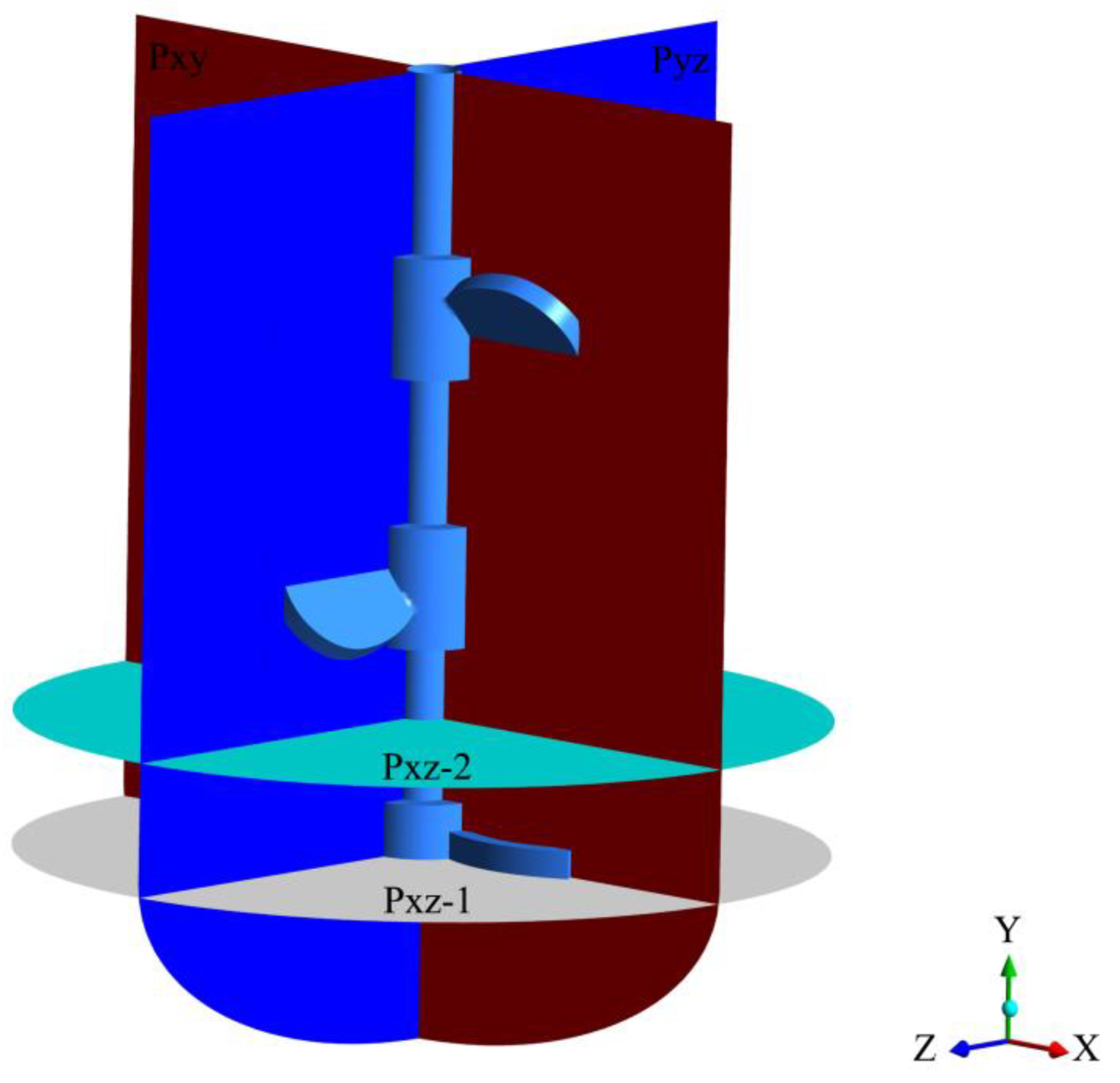
2.2. Geometric Modeling and Meshing

SolidWorks software was used to establish the geometric model, and the DesignModeler module of ANSYS software was used to divide the calculation domain of the stirred fluid. The calculation domain included two areas, specifically, the dynamic and static domains. The dynamic area involves three stirring and rotating areas, as shown in Figure 3. Due to the complex structure of the agitator, it is difficult to manually divide the structured grid as the process is time-consuming and labor-intensive. Therefore, in the ICEM CFD framework, unstructured tetrahedral meshes are used to mesh the mixing model, and local meshes are refined for the dynamic area and blades. The maximum sizes of the overall and local grids are 8 mm and 4 mm, respectively.

2.3. Boundary Conditions and Simulation Settings

As a CFD simulation framework, Fluent provides a variety of multi-motion reference system models, including a multireference frame (MRF) model, mixed plane model (MPM) and sliding mesh model (SMM) [28,29]. The basic idea of the MRF is to use the motion reference system to simulate the rotating area in which the stirrer is located and to use the static reference system to simulate the static area of the reactor that does not include any stirring blades. The rotating area and static area exchange mass and momentum through the interface [30]. The MRF can perform rapid calculations with a high simulation accuracy of the stirring motion. Therefore, this paper uses the MRF method to simulate the stirring motion.
The Reynolds number determines the selection of the turbulence model and laminar flow model for the simulation process. In a stirred reactor, when the Reynolds number is greater than 1000, a turbulence model such as standard k-epsilon should be selected. The Reynolds number in a stirred reactor can be calculated using Formula (1):
R e = ρ N d 2 μ
where ρ is the fluid density, kg/m3; N is the speed of the stirrer, r/s; d is the diameter of the stirrer, m; and μ is the hydrodynamic viscosity, Pa·s.
This paper considers a variety of mixing conditions. When the fluid state was laminar, the laminar flow model was used to perform the numerical simulation. When the fluid state was turbulent, the standard k–ε turbulence model was used for the simulation, and the standard wall function was selected for the near-wall processing method [31,32,33]. The pressure-based solver (PBS) was used to simulate the flow field, and the multiple reference frame method (MRF) was used to simulate the stirring motion. The interface between the static and dynamic areas was set to the sliding surface type, and the two areas exchange data through the interface. Moving wall boundary conditions were applied on the stirring shaft and wall of the blade: the blade and wall of the internal rotating shaft in the moving area have zero rotational velocity relative to the fluid in the moving area. The rotation speed of the wall surface of the rotating shaft relative to the surrounding fluid in the static zone is the actual stirring speed. The inner wall of the stirring tank was set as a nonslip wall, and a symmetric boundary condition was applied on the liquid level.
The continuity equation, momentum equation and turbulence equation used in fluent are as follows (2)~(5):
Continuity equation
ρ t + x i ρ u i = 0
Momentum equation
t ρ u i + x j ρ u i u j = F i ρ x i + τ i j x i j + ρ g i
Standard k-ε turbulence equation
t ( ρ κ ) + x i ρ κ μ i = x j μ + μ i σ κ κ x j + G κ + G b ρ ε Y M + S κ
t ( ρ ε ) + x j ρ ε μ i = x j μ + μ i σ ε ε x j + C 1 ε ε κ G κ + C 3 ε G b C 2 ε ρ ε 2 κ + S ε
where: C1ε = 1.44, C2ε = 1.92.
The coupled algorithm, which exhibits reasonable convergence and advantages in the case of rotating incompressible flow, was used to solve the flow field. The gradient interpolation scheme was selected based on the least square interpolation of the unit volume. The pressure interpolation was based on Standard, and the momentum equation was based on the second-order upwind formula. When the residual error of each indicator is 1 × 10⁻⁴, the calculation was considered to converge, and the solution was obtained.

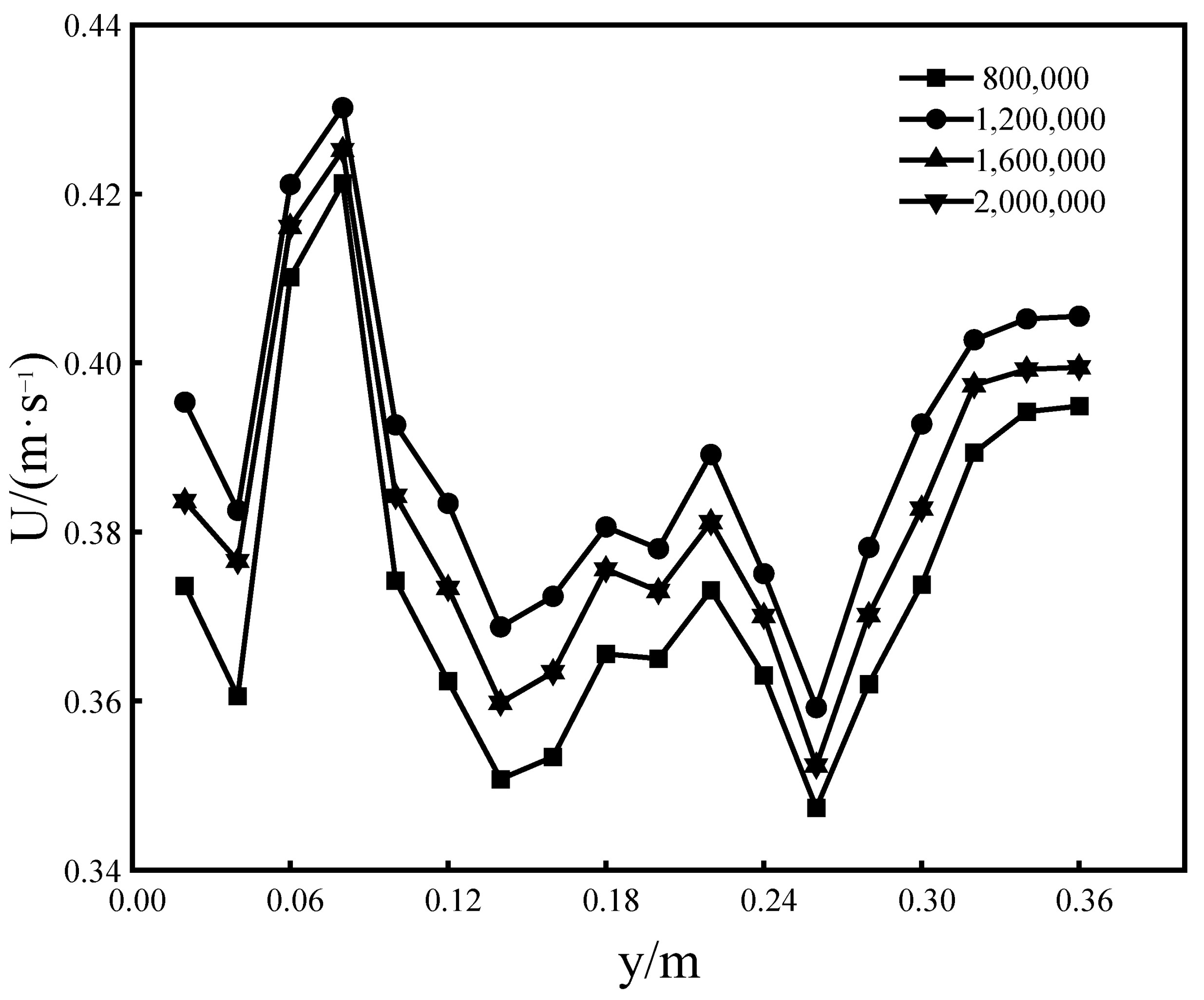
2.4. Grid Independence Analysis

The TBC-A-type agitator was considered as an example to verify the grid independence and simulate the flow field of stirring pure water at a rotation speed of 2 r·s−1. The numerical simulation was divided into four grids with 795,423, 1,206,550, 1,586,604, and 1,985,042 elements. The velocity of the fluid was extracted in the range y = 20–360 mm at the radial position of x = 90 mm in the z = 0 plane. The influence of different grid numbers on the simulation results was analyzed through data comparison. As shown in Figure 4, when the number of grids is 795,423 and 1,206,550, the predicted values for the velocity near x = 90 mm in the mixing vessel are low and high, respectively. As the number of grids increases, the simulation speed tends to stabilize, and the speed simulation results were consistent with those obtained when the number of grids was 1,586,604 and 1,985,042. Considering the accuracy of the simulation results and calculation efficiency, the number of grids was determined to be approximately 1.6 million. At this time, the average y+ value at the propeller blade was 34.21 and the average y+ value at the curved blade was 32.57, which meets the requirements of k-epsilon model for wall y+ value in numerical calculation.

3. Torque Experiment

The DYN-200 torsion sensor (accuracy 0.001 N·m) produced by Bengbu Dayang Sensing System Engineering Co., Ltd. from Bengbu City, China was used to measure the torque of the stirrer in the stirring process. The measured data are displayed in real time via the dynamic torque sensor software in the computer. When no fluid was added to the stirring tank, the idle torque was measured at different speeds. The dynamic torque sensor software was used to record the idle torque change data in real time, and changes in the torque 90 s after the speed stabilizes were intercepted to obtain the average value. The stirring torque was measured during the fluid stirring process in the same conditions, and the experiment was repeated at least 3 times to ensure that the error is less than 3%. The average value of the three data points obtained in the experiment was considered as the torque value in this condition, and the net power loss of fluid stirring was calculated using Formula (6).
P = 2 π N M total M f
where P is the net stirring power, W; N is the stirrer speed, r/s; Mtotal is the liquid stirring torque measured using the torque sensor, N·m; and Mf is the mechanical friction torque when the stirrer is idling, measured with respect to the stirring shaft, N·m. The power criterion NP was calculated from the stirring net power, and the power number curve (NP–Re) was derived. The power number was calculated as
N P = 216000 P ρ N 3 D J 5
In the formula, DJ is the nominal diameter of the stirrer, m.
Table 2 lists the ten working conditions adopted in the experiment.

4. Results and Discussion
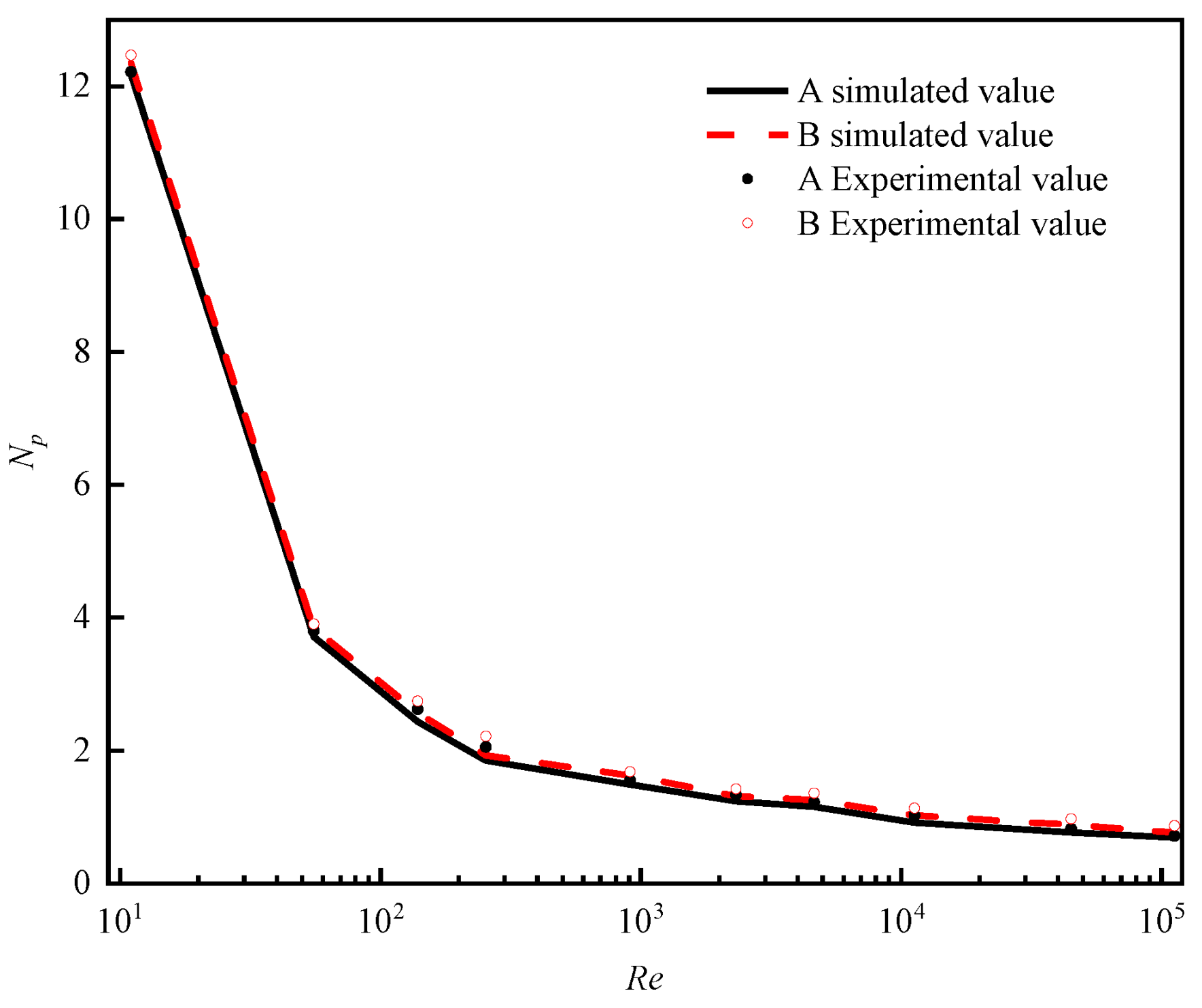
4.1. Power Number

The power numbers determined in the ten conditions through numerical simulation and experiments are shown in Table 3. According to the results, the corresponding power number curve was drawn, as shown in Figure 5.
The power curves of the two groups of three-blade combined agitators (TBCA) obtained in the numerical simulation were similar and in good agreement with the experimental results. Moreover, the measurement results were consistent with the change trend of the Reynolds number. When Re = 11, the power number was considerably large. As the Reynolds number increased, the power number gradually decreased linearly, and the downward trend began to retard after the transition zone was reached. When Re > 104, the power criterion NP did not change with increasing Reynolds number and remained nearly constant. The numerical simulation results can satisfy the requirements of engineering practice, which demonstrates the rationality of the simulation method and parameter settings.

4.2. Flow Field Characteristics

The 2nd (high-viscosity laminar flow) and 9th (low-viscosity turbulent flow) operating conditions in Table 2 were considered to examine the velocity field and turbulent kinetic energy distribution when the fluid in the stirred vessel is water and glycerin, and the stirring speed N = 2 r·s−1. As shown in Figure 6, four sampling planes were selected, in which sampling plane 1 is located in the middle longitudinal section Pxy of the stirring vessel, sampling plane 2 is located in the middle longitudinal section Pyz of the stirring vessel, sampling plane 3 is located in the horizontal section Pxz-1 70 mm from the bottom and sampling plane 4 is located in the horizontal section Pxz-2 with a distance of 120 mm from the bottom. The axial position y = 120 mm is located in the joint action area of the bottom curved blade and middle propeller blade. Selecting this position for flow field velocity analysis can better reflect the flow field changes in the middle area of the curved blade and propeller blade.

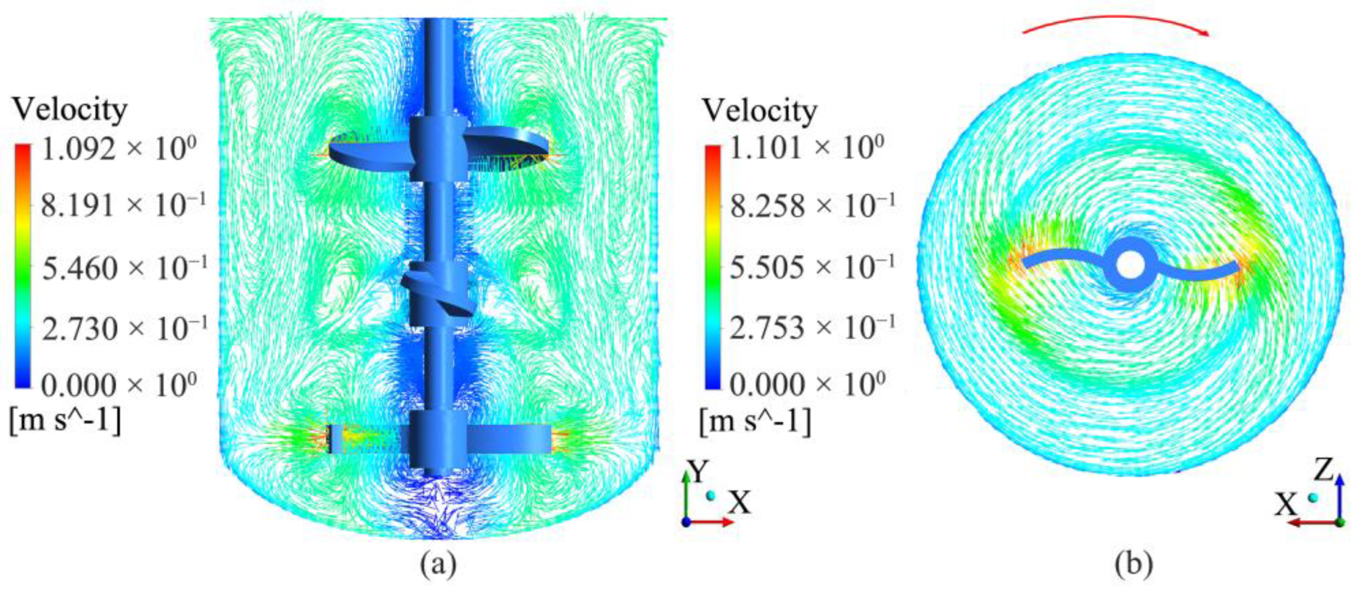
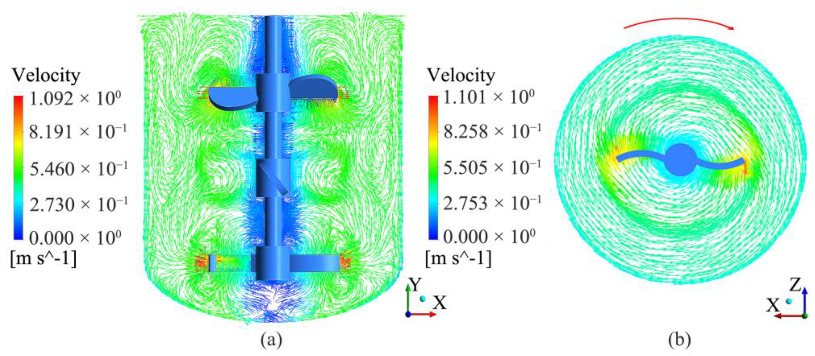
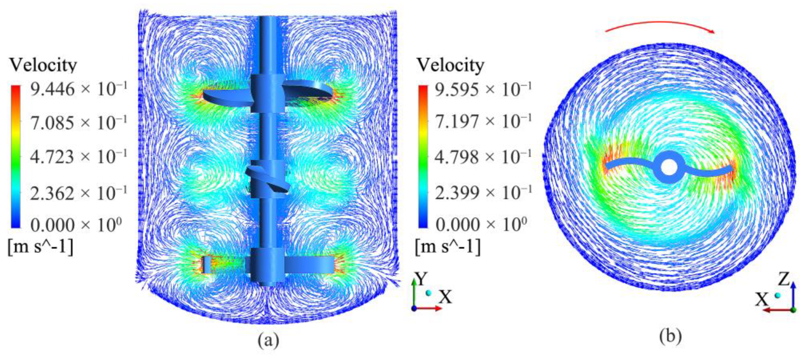
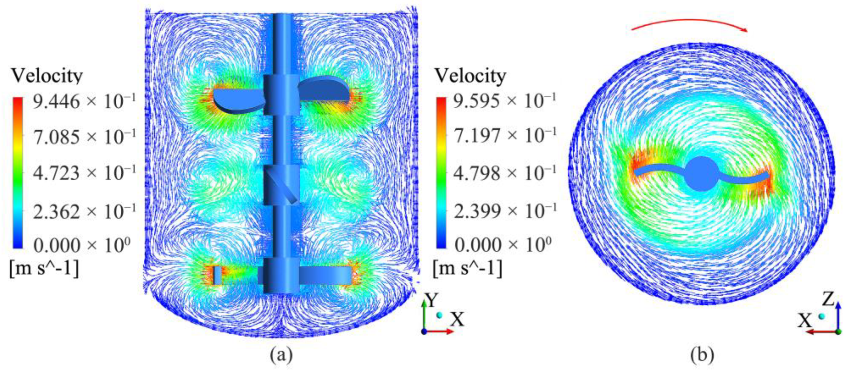
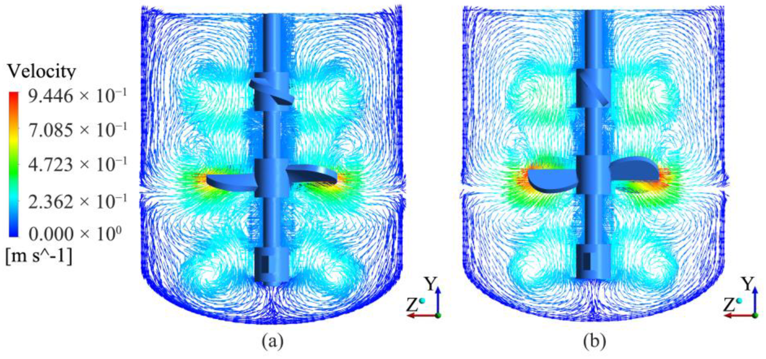
4.2.1. Velocity Field

The vector diagram of the stirring speed of the two stirrers when the medium is water and Re = 44,910 is shown in Figure 7, Figure 8 and Figure 9. In Figure 7 and Figure 8, the flow patterns produced by the two kinds of three-blade combined agitators (TBCAs) are similar. Axial flow is dominant near the propeller blades, and typical radial flow occurs near the curved blades. However, the velocity distribution in the middle longitudinal section (Pxy) shows that at a given stirring speed and Reynolds number, the overall velocity of the fluid in the container was higher when the TBC-B stirrer was used. Planar propeller blades can produce a larger driving force than helical propeller blades. In the horizontal section (Pxz-1) of the agitator, for a given curved blade shape (θ = 30°) and speed (N = 2 r·s−1), affected by the bending angle of the curved blade, the high-velocity range at the front end of the curved blade was effectively enhanced, and the fluid velocity near the inner curved blade of the TBC-B type agitator was significantly high, indicating that the combination of propeller blades and curved blades in the TBC-B type agitator can increase the overall flow velocity of the fluid in the container.
Figure 9 shows the fluid velocity vector of two three-blade combined agitators in sampling plane 2 (Pyz). In sampling plane 2 (Pyz), the fluid velocity in the container was large when the TBC-B stirrer was used. Under the direct stirring action of the intermediate propulsion blade, a typical axial flow was formed near the propulsion blade. It can also be seen from Figure 8 that the axial vortex formed near the propeller blade in the right figure is larger, which is more conducive to the axial flow mixing of the top fluid. There are two small vortices in the left picture at the bottom of the stirring vessel, but no vortex was formed in the right picture, which is conducive to the exchange of the upper and lower layers of media and improves the mixing uniformity of the bottom fluid. The overall analysis shows that the combination of propeller blades and curved blades in the TBC-B type agitator is beneficial to improve the fluid flow speed and mixing uniformity.
Figure 10, Figure 11 and Figure 12 show the velocity vector diagram when the medium is glycerol and Re = 55.5. In Figure 10 and Figure 11, when stirring highly viscous fluids, the flow field near the blades of the two TBC stirrers exhibits a high speed due to the driving force of the stirrer. The fluid area far from the mixing blade is subject to high viscous resistance, the Reynolds number is small, and the flow is relatively gentle. Moreover, the fluid velocity near the propeller blades in the TBC-B agitator is significantly high, and the fluid flow velocity near the curved blades (θ = 30°) is increased, which enhances the radial diffusion capacity of the fluid at the bottom of the stirring vessel.
Figure 12 shows the fluid velocity vector of two three-blade combined agitators in sampling plane 2 (Pyz). In the area away from the blades of the stirring paddle, large axial vortices were generated in the TBC-B type agitator and TBC-A, which is conducive to the exchange of upper and lower media. In the figure on the left, there are two small vortices at the lower end of the propeller blade in the middle, which is not conducive to fluid diffusion, while the design of the planar propeller blade in the figure on the right avoids the formation of small vortices. The overall analysis shows that the combination of propeller blades and curved blades in the TBC-B type agitator is beneficial to increase the fluid flow speed and enhance the fluid diffusion ability.

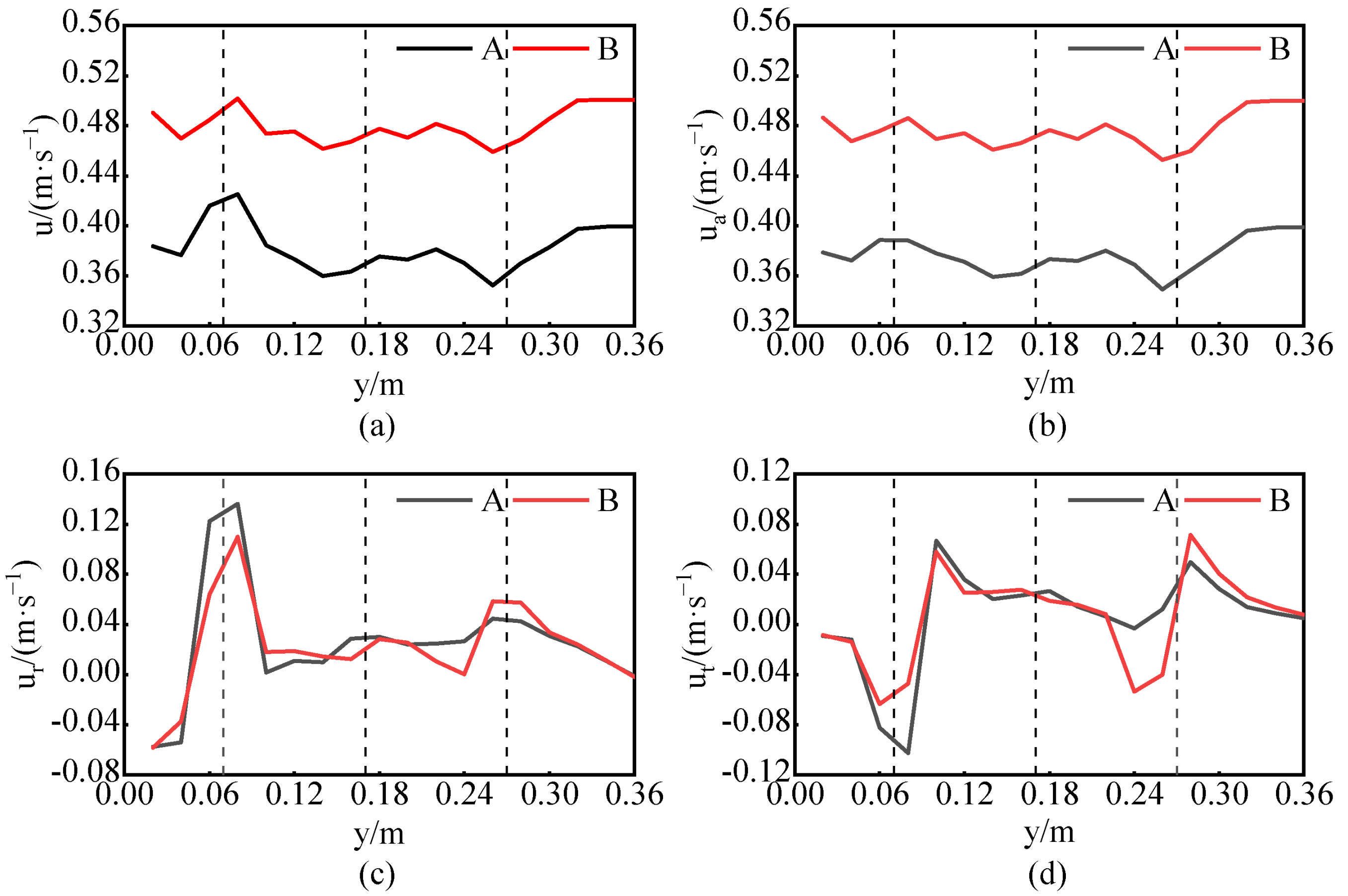
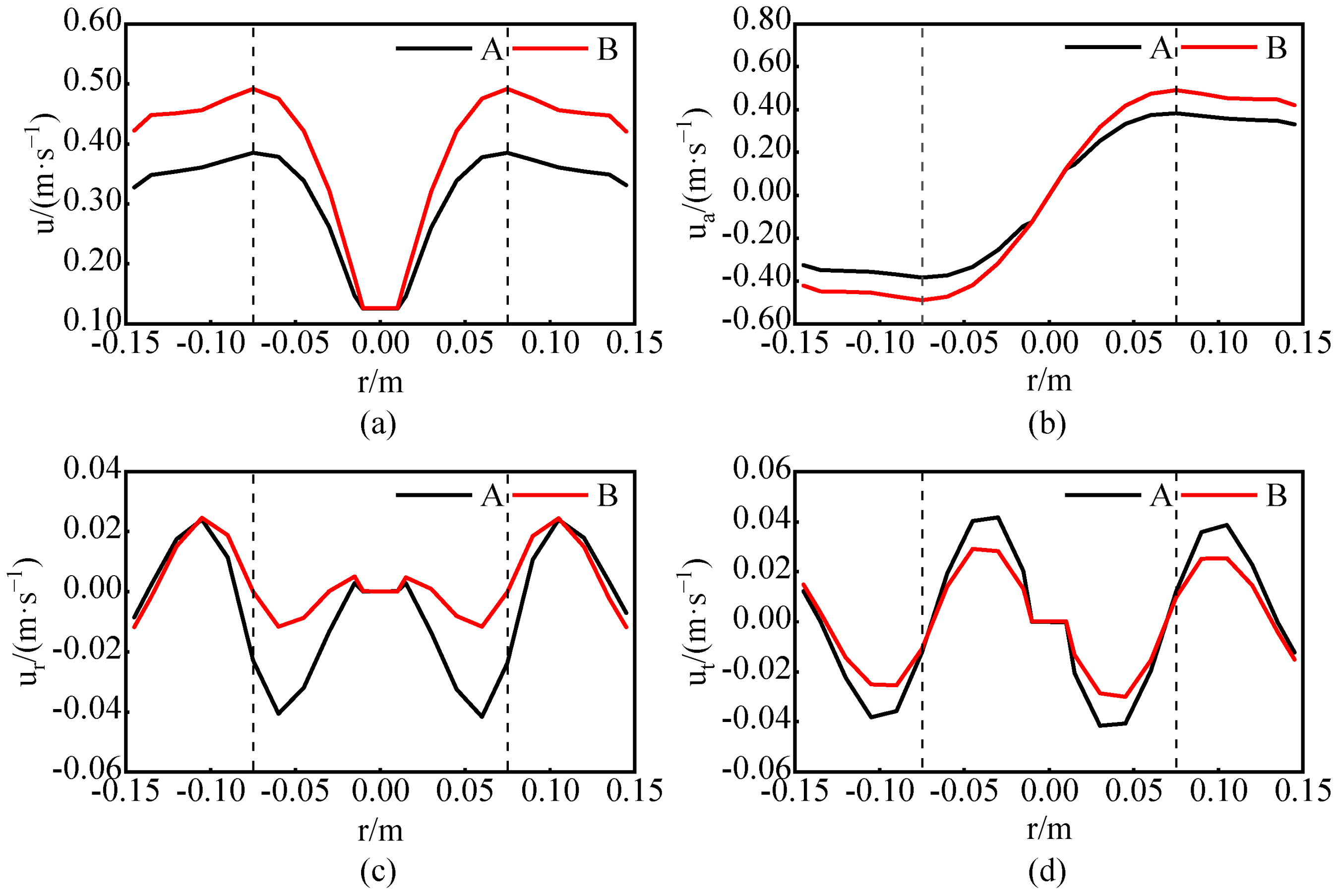
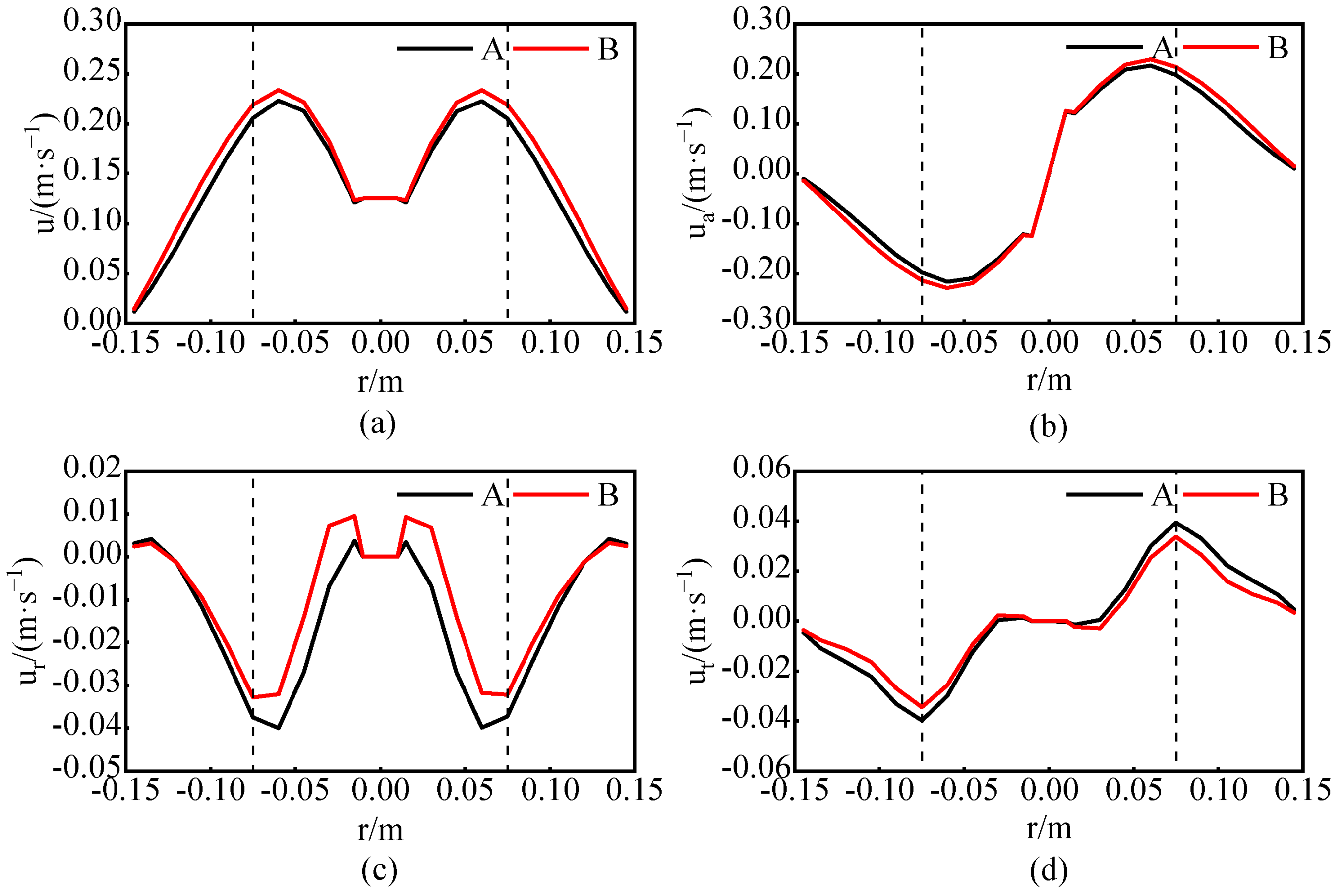
4.2.2. Velocity Distribution

Horizontal and vertical positions in the middle longitudinal section (Pxy) of the mixing vessel were selected to specify the speed distribution of the TBC-A and TBC-B agitators. Figure 13 and Figure 14 show the velocity distributions at radial position r = 90 mm and axial position y = 120 mm when the stirring medium is water and Re = 44,910, respectively. Figure 13 shows that the total speed of the TBC-B-type agitator is considerably higher than that of the TBC-A-type agitator, and the maximum increase in the total speed is 30.3%. Except for those at positions near the curved blades, the axial velocities of the two agitators are similar to the total velocity of the fluid, and the axial velocity of the TBC-B-type agitator is significantly higher than that of the TBC-A-type agitator. The bottom position of the mixing vessel corresponds to a large radial velocity due to the action of the curved blades. Figure 14 shows that at y = 120 mm, the total speed and axial speed of the TBC-B type agitator are greater than those of the TBC-A type agitator, and with the increase in the radial coordinate, the total speed of the TBC-B type agitator first decreases and later increases until the end of the blade, with a maximum difference udv = 0.106 m·s−1 in the corresponding area of the blade end. The radial speed of the TBC-B type agitator at the far end of the blade is greater than that of the TBC-A type agitator, while the tangential speed is always lower than that of the TBC-A type agitator. This analysis shows that in the near-paddle zone, the TBC-B agitator has a relatively large speed and a relatively uniform axial velocity, which can enhance the axial circulation capacity of the flow field. At the distal end of the blade, the axial and radial speeds of the TBC-B agitator are high, while the tangential speed is significantly reduced. This finding shows that the vertical distribution combination of the curved blades and central planar propeller blade b in the TBC-B agitator can increase the circulating flow capacity of the flow field. Without a baffle, the TBC-B agitator can weaken the tangential flow capacity of the flow field, which can help transfer energy to the area far from the agitator and enhance the uniformity of fluid mixing.
The velocity distributions of the flow field in the vessel when the medium is glycerin and Re = 55.5 are shown in Figure 15 and Figure 16. Figure 15 shows that in the near paddle area r = 90 mm, the total speed of the TBC-B type agitator is greater than that of the TBC-A type agitator, and the maximum value pertains to the top propeller stirring blade. The maximum increase in speed is 22.1%. According to the axial and radial velocity curves, the TBC-B type agitator exhibits an increase in the two velocity components. The maximum radial velocity occurs at the height of the curved blade at y = 75 mm, and this value is only 18.7% lower than that when the medium is water. The corresponding value for the TBC-A agitator is 25.9% smaller. As shown in Figure 16, at the axial height y = 120 mm, under the joint action of the curved blade and intermediate propulsion blade, the speed of the two kinds of blades near the mixing shaft first increases and later decreases with increasing radial coordinates. The tangential speed of the TBC-B type agitator is lower than that of the TBC-A type agitator, indicating that the TBC-B type agitator exhibits a higher circulating flow capacity in the mixing area of the curved blade and middle propeller blade.
The analysis of the velocity distributions in two working conditions of water and glycerol demonstrates that the speed of the TBC-B type agitator is higher than that of TBC-A type agitator near the propeller area and at the far end of the blade, and the maximum increase in the total speed is 30.3%. The vertical combination of the curved blade and propulsion blade in TBC-B type agitator can effectively reduce the tangential velocity, increase the two velocity components of the axial and radial velocities, increase the circulating flow capacity of the flow field, and reduce the tangential flow capacity of the flow field without the baffle, which can help enhance the fluid mixing uniformity. The TBC-B type agitator exhibits a superior velocity distribution compared to that of the TBC-A type agitator in low and high viscosity mixing media, and the TBC-B type agitator can more effectively enhance the fluid velocity in the high viscosity mixing medium.

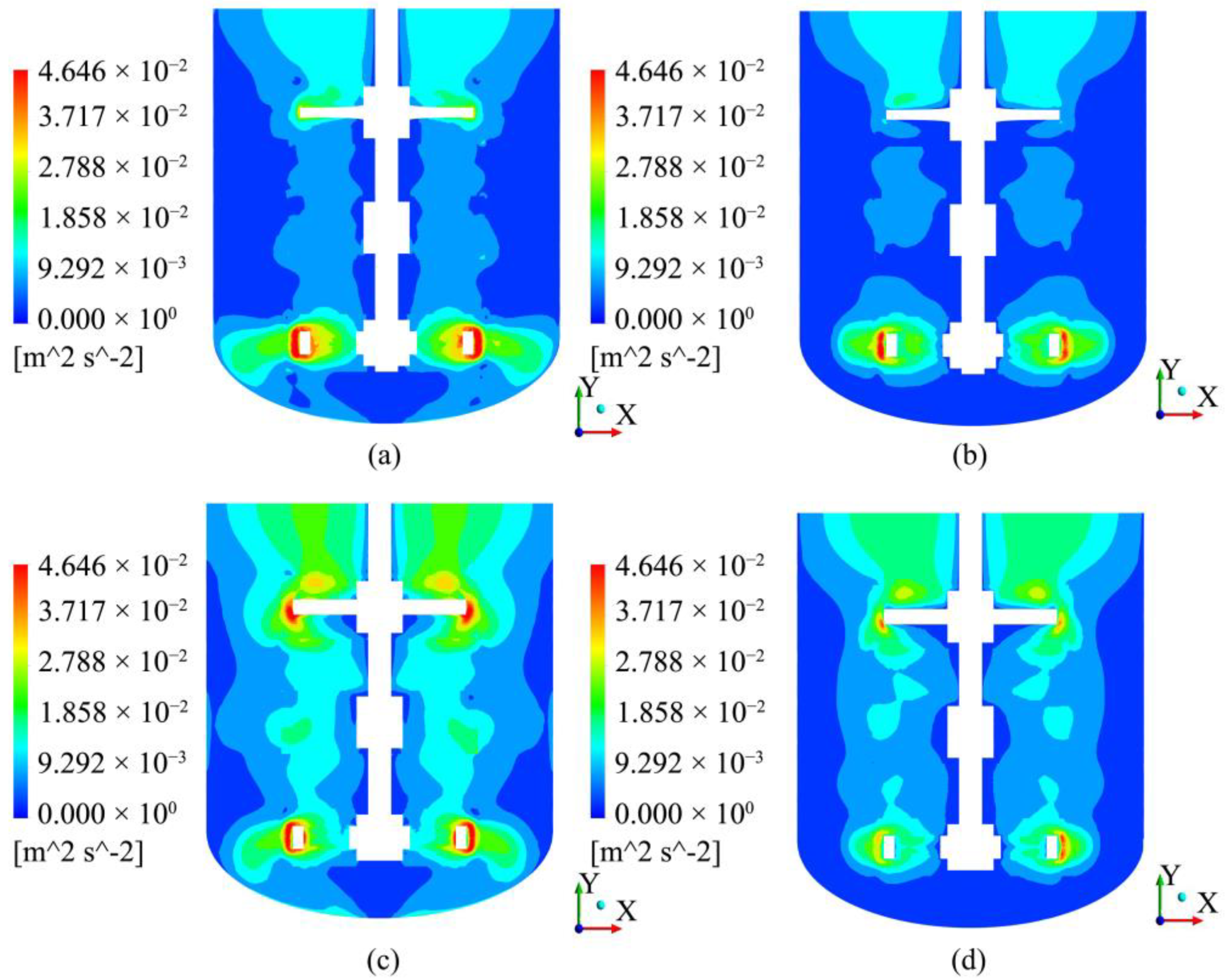
4.2.3. Turbulent Kinetic Energy Analysis

The turbulent kinetic energy and its dissipation rate distribution for a fluid in a stirring vessel are important factors affecting macro- and micromixing. The turbulent kinetic energy (k) can be calculated as
k = 1 2 u 2 ¯ + v 2 ¯ + w 2 ¯
where u’, v’ and w’ represent radial, axial and tangential pulsating velocities, respectively. Figure 17 and Figure 18 show cloud diagrams of the turbulent kinetic energy distribution at the two middle longitudinal sections of Pxy and Pyz in the mixing vessel at the same speed and different Reynolds numbers, respectively.
Figure 17 and Figure 18 show that when the rotation speed N = 2 r·s−1, the turbulent kinetic energy for the fluid with viscosity μ = 0.023 Pa·s in the two figures (a), (c) is more evenly distributed than that for the fluid with viscosity μ = 0.001 Pa·s. The value of the turbulent kinetic energy in the flow area is significantly increased, which indicates that the TBC-type agitator exhibits a superior mixing effect when agitating medium-viscosity fluids. Moreover, the turbulent kinetic energy distribution at the two sampling planes of Pxy and Pyz when the TBC-A type agitator is used is not uniform, and the turbulent kinetic energy of (a) and (b) in the two figures is less than 0.01 m2/s2. The corresponding region is relatively large, and thus, uneven mixing may occur in this area. Compared with those for the TBC-A type agitator, the turbulent kinetic energy distribution for the TBC-B type agitator is more uniform, and the turbulent kinetic energy is significantly higher. In the circulating flow area of Figure 17a,c, the turbulent kinetic energy for the TBC-B type agitator ranges from 0.0103 to 0.0713 m2/s2. The corresponding range for the TBC-A type agitator is 0.0067 to 0.0680 m2/s2. Thus, the turbulent kinetic energy for the TBC-B type agitator is significantly higher than that for the TBC-A type agitator. The comparison of the turbulent kinetic energy distributions at the two sampling planes Pxy and Pyz indicates that the turbulent kinetic energy distribution in these sections is similar when the vertically assembled propeller blades and curved blades operate simultaneously. Thus, the three-blade combination method can ensure the uniformity of the turbulent kinetic energy distribution of the fluid. Under the same conditions, the TBC-B type agitator exhibits a superior fluid discharge performance and can be used in a wider viscosity range. The three-blade combination of planar propeller blades and curved blades is conducive to ensuring the full mixing of fluids.

4.2.4. Dead Zone Percentage

To quantitatively describe the fluid mixing performance in the mixing container, the area in which the flow velocity in the mixing container is less than the maximum fluid velocity of 0.01 is defined as the mixing dead zone, which pertains to the dead angle of the mixing kinetic energy. The fluid in the dead zone does not participate in the momentum and mass exchange in the mixing container, which are key factors affecting the uniformity and time of fluid mixing. The maximum fluid velocity can be calculated as
U tip = 2 π N D J 2
Figure 19 illustrates the comparison of the variation in the mixing dead zone percentage for two kinds of three-blade combined agitators (TBCAs) with the Reynolds number. With the continuous increase in Re, the dead zone percentage for the two kinds of three-blade combined agitators (TBCAs) gradually decreases from approximately 8.5% in the laminar flow state to less than 0.05%. When Re = 55.5, the percentage of the dead zone decreases to approximately 3%, indicating that the three-blade combined agitators (TBCAs) can fully mix the fluid under laminar flow, transition flow and turbulence. When Re = 44,910, the dead zone percentage of the TBC-A type agitator is 0.0216. Moreover, the dead zone percentage of the TBC-B type agitator is always smaller than that of the TBC-A type agitator, indicating that the mixing effect of the TBC-B type agitator is superior to that of the TBC-A type agitator.

5. Conclusions

The variation law of the power number of a TBC-B-type agitator with the Reynolds number is studied through numerical simulation and experiments. By analyzing the velocity field, velocity distribution, turbulent kinetic energy distribution and dead zone distribution, the flow characteristics of TBC-B-type agitators are examined, and the following conclusions are obtained.
(1) The power curves (NPRe) of two three-blade combined agitators from laminar flow to the turbulent state are obtained. The numerical simulation results are in agreement with the experimental results. The theoretical prediction results can satisfy the requirements of engineering practice, and the simulation method and parameter settings are reasonable.
(2) The analysis of the flow field shows that the flow pattern of the TBC-B type agitator is the same as that of the TBC-A type agitator. The bottom part is dominated by radial flow, and the middle and upper parts are dominated by axial flow. Notably, the fluid velocity distribution associated with the TBC-B-type agitator is relatively uniform, and the increase in the contact area of the planar propeller blade produces a stronger driving force, which can enhance the overall flow velocity of the fluid and increase the fluid flow velocity near the bottom curved blades. The radial diffusion capacity of the fluid at the bottom of the container is increased.
(3) According to the quantitative comparative analysis of the fluid velocity distribution, when the stirring medium is water and Re = 44,910, the TBC-B type agitator can increase the fluid velocity near the paddle area, and without a vertical mixing baffle, the vertical combination of the curved blades and planar propeller blades can also effectively reduce the tangential velocity. An increase in the two velocity components of the axial and radial velocities can help enhance the uniformity of fluid mixing. When the stirring medium is glycerin and Re = 55.5, the speed of the TBC-B type agitator in the near paddle area and distal end of the blade is higher than that in the case of the TBC-A type agitator. Compared with that of the low-viscosity stirring fluid, in the case of the high-viscosity stirring fluid, the TBC-B type agitator can more effectively increase the fluid velocity.
(4) When the rotation speed is N = 2 r·s−1, the TBC-B-type agitator exhibits a superior mixing effect on the medium viscosity fluid. Compared with the TBC-A type agitator, the turbulent kinetic energy in the mixing vessel with the TBC-B type agitator is more evenly distributed. In the circulating flow area, the turbulent kinetic energy in the mixing vessel with the TBC-B type agitator is higher than that in the case with the TBC-A type agitator. The three-blade combination mode of the three-blade combined agitators (TBCAs) can ensure the uniformity of the turbulent kinetic energy distribution of the fluid. Under the same conditions, the TBC-B-type agitator exhibits a superior fluid discharge performance and can be used in a wider viscosity range. The three-blade combination of the planar propeller blades and curved blades can help realize the full mixing of fluids.
(5) The TBC agitator can fully mix the fluid under laminar flow, transitional flow and turbulent flow. Moreover, the TBC-B type agitator always has a smaller dead zone percentage than the TBC-A type agitator, indicating that the mixing effect of the TBC-B type agitator is superior to that of the TBC-A type agitator.
The research and conclusions on the flow field characteristics in this paper are based on numerical simulation, which has some limitations, and the relevant results still need to be verified by further experiments.

Author Contributions

Conceptualization, Y.Z. and L.Z.; software, Y.Z; validation, H.W., X.M. and S.Y.; resources, Y.Z.; data curation, Y.Y. and H.B.; writing—original draft preparation, Y.Z.; writing—review and editing, Y.Z. and L.Z.; project administration, L.Z.; funding acquisition, L.Z. All authors have read and agreed to the published version of the manuscript.

Funding

This research was funded by the National Natural Science Foundation of China, grant number 52065055.

Institutional Review Board Statement

Not applicable.

Informed Consent Statement

Not applicable.

Data Availability Statement

All relevant data presented in the article are stored according to institutional requirements and, as such, are not available online. However, all data used in this Manuscript can be made available upon request to the authors.

Conflicts of Interest

The authors declare no conflict of interest.

Abbreviations

Symbol description
T the inner diameter of the stirring tank, mm
H liquid level height, mm
h elliptical head height, mm
C1 distance from bottom, mm
C2, C3 distance between the blades, mm
d curved blade width, mm
θ inclination angle of the front and rear blades of the curved blade, °
DJcnominal diameter of curved blade, mm
DJnominal diameter of propelling blade, mm
W the section leaf width, mm
δ angle between the section and stirring axis, °
N speed of the stirrer, r·s−1
P the net stirring power, W
kturbulent kinetic energy, m2·s−2
ua, ur, utthey are axial, radial and tangential velocities respectively, m·s−1
ε turbulent dissipation rate, m2·s−3
μfluid viscosity, Pa·s
ρfluid density, kg·m−3

References

  1. Gu, D.; Cheng, C.; Liu, Z.; Wang, Y. Numerical simulation of solid-liquid mixing characteristics in a stirred tank with fractal impellers. Adv. Powder Technol. 2019, 30, 2126–2138. [Google Scholar] [CrossRef]
  2. Hoseini, S.S.; Najafi, G.; Ghobadian, B.; Akbarzadeh, A.H. Impeller shape-optimization of stirred-tank reactor: CFD and fluid structure interaction analyses. Chem. Eng. J. 2021, 413, 127497. [Google Scholar] [CrossRef]
  3. Martínez-Delgadillo, S.A.; Alonzo-Garcia, A.; Mendoza-Escamilla, V.X.; González-Neria, I.; Antonio Yáñez-Varela, J. Analysis of the turbulent flow and trailing vortices induced by new design grooved blade impellers in a baffled tank. Chem. Eng. J. 2019, 358, 225–235. [Google Scholar] [CrossRef]
  4. Stuparu, A.; Susan-Resiga, R.; Tanasa, C. CFD Assessment of the Hydrodynamic Performance of Two Impellers for a Baffled Stirred Reactor. Appl. Sci. 2021, 11, 4949. [Google Scholar] [CrossRef]
  5. Tokura, Y.; Miyagawa, K.; Uddin, M.A.; Kato, Y. Suspension pattern and rising height of sedimentary particles with low concentration in a mechanically stirred vessel. Can. J. Chem. Eng. 2021, 99, 410–420. [Google Scholar] [CrossRef]
  6. Yang, F.; Cao, M.; Zhang, C.; Liu, X. Vibration characteristics of the flexible-blade Rushton impeller. Chin. J. Chem. Eng. 2020, 72, 1975–1986. [Google Scholar]
  7. Basbug, S.; Papadakis, G.; Vassilicos, J.C. Reduced mixing time in stirred vessels by means of irregular impellers. Phys. Rev. Fluids 2018, 3, 084502. [Google Scholar] [CrossRef] [Green Version]
  8. Basbug, S.; Papadakis, G.; Vassilicos, J.C. Reduced power consumption in stirred vessels by means of fractal impellers. Aich. J. 2018, 64, 1485–1499. [Google Scholar] [CrossRef]
  9. Li, W.; Zhou, Y.; Yuan, M.; He, H.; Sun, J. Comparative study of the flow characteristics in several frame-type impeller stirred tanks. Chin. J. Chem. Eng. 2020, 72, 1998–2005. [Google Scholar]
  10. Xu, Y.; Wang, J.; Wu, Y.; Luo, P. Study on the flow characteristics and mixing performance of multi-blade combined agitator. Chin. J. Chem. Eng. 2020, 71, 4964–4970. [Google Scholar]
  11. Kamla, Y.; Ameur, H.; Karas, A.; Arab, M.I. Performance of new designed anchor impellers in stirred tanks. Chem. Pap. 2020, 74, 779–785. [Google Scholar] [CrossRef]
  12. Jaszczur, M.; Mlynarczykowska, A. A General Review of the Current Development of Mechanically Agitated Vessels. Processes 2020, 8, 982. [Google Scholar] [CrossRef]
  13. Ameur, H. Effect of the shaft eccentricity and rotational direction on the mixing characteristics in cylindrical tank reactors. Chin. J. Chem. Eng. 2016, 24, 1647–1654. [Google Scholar] [CrossRef]
  14. Devi, T.T.; Kumar, B. Scale up criteria for dual stirred gas-liquid unbaffled tank with concave blade impeller. Korean J. Chem. Eng. 2014, 31, 1339–1348. [Google Scholar] [CrossRef]
  15. Dapelo, D.; Bridgeman, J. Assessment of mixing quality in full-scale, biogas-mixed anaerobic digestion using CFD. Bioresource Technol. 2018, 265, 480–489. [Google Scholar] [CrossRef] [Green Version]
  16. Dapelo, D.; Alberini, F.; Bridgeman, J. Euler-Lagrange CFD modelling of unconfined gas mixing in anaerobic digestion. Water Res. 2015, 85, 497–511. [Google Scholar] [CrossRef] [Green Version]
  17. Satjaritanun, P.; Regalbuto, J.R.; Regalbuto, J.A.; Tippayawong, N.; Shimpalee, S. Mixing optimization with inward flow configuration contra-rotating impeller, baffle-free tank. Alexaandria Eng. J. 2021, 60, 3759–3779. [Google Scholar] [CrossRef]
  18. Foukrach, M.; Ameur, H. Effect of impeller blade curvature on the hydrodynamics and power consumption in a stirred tank. Chem. Ind. Chem. Eng. Q. 2020, 26, 259–266. [Google Scholar] [CrossRef] [Green Version]
  19. Steiros, K.; Bruce, P.J.K.; Buxton, O.R.H.; Vassilicos, J.C. Effect of blade modifications on the torque and flow field of radial impellers in stirred tanks. Phys. Rev. Fluids 2017, 2, 94802. [Google Scholar] [CrossRef]
  20. Jaszczur, M.; Młynarczykowska, A.; Demurtas, L. Effect of Impeller Design on Power Characteristics and Newtonian Fluids Mixing Efficiency in a Mechanically Agitated Vessel at Low Reynolds Numbers. Energies 2020, 13, 640. [Google Scholar] [CrossRef] [Green Version]
  21. Bliatsiou, C.; Malik, A.; Boehm, L.; Kraume, M. Influence of Impeller Geometry on Hydromechanical Stress in Stirred Liquid/Liquid Dispersions. Ind. Eng. Chem. Res. 2019, 58, 2537–2550. [Google Scholar] [CrossRef]
  22. Liang, Y.; Gao, D.; Bai, L. Numerical Simulation of the Laminar Flow Field and Mixing Time in Stirred Tank with Double Layer Impeller. J. Mech. Eng. 2015, 51, 185–195. [Google Scholar] [CrossRef]
  23. Lu, C.; Zhang, Z.; Zhao, Q.; Wang, S.; Zhang, T.; Liu, Y. Numerical Simulation of Enhanced Oil-Water Separation in a Three-Stage Double-Stirring Extraction Tank. China Petrol. Process Petrochem. 2015, 17, 121–126. [Google Scholar]
  24. Zhou, Y.; Yuan, M.; Sun, C. Investigating on flow field in stirred tank equipped with improved frame type combined impellers. Chem. Ind. Eng. Progress. 2019, 38, 5306–5313. [Google Scholar]
  25. Sun, Z.; Ni, H.; Chen, H.; Li, S.; Lu, G.; Yu, J. Designing and optimizing a stirring system for a cold model of a lithium electrolysis cell based on CFD simulations and optical experiments. RSC Adv. 2015, 5, 4503–84516. [Google Scholar] [CrossRef]
  26. Liu, P.; Zhang, R.; Yang, X.; Zhang, Y.; Hu, Z. Numerical Simulation of Turbo-type and Push-type Stirred Tanks. Chem. Eng. Mach. 2017, 44, 84–87. [Google Scholar]
  27. Stelmach, J.; Kuncewicz, C. Effect of propeller impeller blade profile on hydrodynamics and power consumption. Przem. Chem. 2017, 96, 2348–2352. [Google Scholar]
  28. Mendoza, E.; Banales, A.L.; Cid, E.; Xuereb, C.; Poux, M.; Fletcher, D.F.; Aubin, J. Hydrodynamics in a stirred tank in the transitional flow regime. Chem. Eng. Res. Des. 2018, 132, 865–880. [Google Scholar] [CrossRef] [Green Version]
  29. Sutudehnezhad, N.; Zadghaffari, R. CFD Analysis and Design Optimization in a Curved Blade Impeller. Int. J. Chem. React. Eng. 2017, 15, 137–150. [Google Scholar] [CrossRef]
  30. Xiang, C.; Li, L.; Wang, K.; Zhao, Q. Numerical analysis of flow field and optimization of agitation parameters in solid state fermentation reactor. J. Harbin Inst. Technol. 2020, 53, 1–11. [Google Scholar]
  31. Cheng, D.; Wang, S.; Yang, C.; Mao, Z. Numerical Simulation of Turbulent Flow and Mixing in Gas-Liquid-Liquid Stirred Tanks. Ind. Eng. Chem. Res. 2017, 56, 13051–13064. [Google Scholar] [CrossRef] [Green Version]
  32. Devi, T.T.; Kumar, B. Mass transfer and power characteristics of stirred tank with Rushton and curved blade impeller. Eng. Sci. Technol. Int. J. 2017, 20, 730–737. [Google Scholar] [CrossRef] [Green Version]
  33. Li, X.; Zhao, H.; Zhang, Z.; Liu, Y.; Zhang, T. Numerical optimization for blades of Intermig impeller in solid-liquid stirred tank. Chin. J. Chem. Eng. 2021, 29, 57–66. [Google Scholar] [CrossRef]
Figure 1. Schematic of the experimental device.
Processes 09 01962 g001
Figure 2. Structural characteristics of two three-blade combined agitators, contain angle between section and mixing axis δ, Sectional leaf width w.
Processes 09 01962 g002
Figure 3. Mesh division.
Processes 09 01962 g003
Figure 4. Total velocity distribution.
Processes 09 01962 g004
Figure 5. Curve of the power criterion versus the Reynolds number.
Processes 09 01962 g005
Figure 6. Sampling plane.
Processes 09 01962 g006
Figure 7. Velocity vector diagram when the medium is water and Re = 44,910. (a) TBC-A type agitator, Plane 1:XY,Z = 0 mm; (b) TBC-A type agitator, Plane 3:XZ,Y = 70 mm.
Processes 09 01962 g007
Figure 8. Velocity vector diagram when the medium is water and Re = 44,910. (a) TBC-B type agitator, Plane 1:XY,Z = 0 mm; (b) TBC-B type agitator, Plane 3:XZ,Y = 70 mm.
Processes 09 01962 g008
Figure 9. Velocity vector diagram when the medium in YZ section is water and Re = 44,910. (a) TBC-A type agitator, Plane 2:YZ,X = 0 mm; (b) TBC-B type agitator, Plane 2: YZ,X = 0 mm.
Processes 09 01962 g009
Figure 10. Velocity vector diagram when the medium is glycerin and Re = 55.5. (a) TBC-A type agitator, Plane 1:XY,Z = 0 mm; (b) TBC-A type agitator, Plane 3:XZ,Y = 70 mm.
Processes 09 01962 g010
Figure 11. Velocity vector diagram when the medium is glycerin and Re = 55.5. (a) TBC-B type agitator, Plane 1:XY,Z = 0 mm; (b) TBC-B type agitator, Plane 3:XZ,Y = 70 mm.
Processes 09 01962 g011
Figure 12. Velocity vector diagram when the medium in YZ section is glycerin and Re = 55.5. (a) TBC-A type agitator, Plane 2:YZ,X = 0 mm; (b) TBC-B type agitator, Plane 2: YZ,X = 0 mm.
Processes 09 01962 g012
Figure 13. Velocity distribution at the radial position r = 90 mm when the medium is water and Re = 44,910. The three dotted lines are the centerline positions of the three blades. (a) Total speed comparison; (b) Axial velocity comparison; (c) Radial velocity comparison; (d)Tangential velocity comparison.
Processes 09 01962 g013
Figure 14. Velocity distribution at the axial position y = 120 mm when the medium is water and Re = 44,910. The distance between the two curves is the nominal diameter of the blade. (a) Total speed comparison; (b) Axial velocity comparison; (c) Radial velocity comparison; (d) Tangential velocity comparison.
Processes 09 01962 g014
Figure 15. Velocity distribution at the radial position r = 90 mm when the medium is glycerol and Re = 55.5. The three dotted lines are the centerline positions of the three blades. (a) Total speed comparison; (b) Axial velocity comparison; (c) Radial velocity comparison; (d) Tangential velocity comparison.
Processes 09 01962 g015
Figure 16. Velocity distribution at the axial position y = 120 mm when the medium is glycerol and Re = 55.5. The distance between the two curves is the nominal diameter of the blade. (a) Total speed comparison; (b) Axial velocity comparison; (c) Radial velocity comparison; (d) Tangential velocity comparison.
Processes 09 01962 g016
Figure 17. Cloud diagram for the turbulent kinetic energy in the XY section. (a) Re = 2316.5, μ = 0.023 Pa·s, TBC-A type agitator; (b) Re = 44,910, μ = 0.001 Pa·s, TBC-A type agitator; (c) Re = 2316.5, μ = 0.023 Pa·s, TBC-B type agitator; (d) Re = 44,910, μ = 0.001 Pa·s, TBC-B type agitator.
Processes 09 01962 g017
Figure 18. Cloud diagram of the turbulent kinetic energy in the YZ section. (a) Re = 2316.5, μ = 0.023 Pa·s, TBC-A type agitator; (b) Re = 44,910, μ = 0.001 Pa·s, TBC-A type agitator; (c) Re = 2316.5, μ = 0.023 Pa·s, TBC-B type agitator; (d) Re = 44,910, μ = 0.001 Pa·s, TBC-B type agitator.
Processes 09 01962 g018
Figure 19. Dead zone percentage.
Processes 09 01962 g019
Table 1. Parameters of two kinds of propeller blade structures.
SectionSectional Leaf Width (w/mm)Angle between the Section and Stirring Axis (δ/°)
Blade aBlade bBlade aBlade b
S034.2129.7146.2036.87
S140.7138.2952.6936.87
S248.3444.1558.3636.87
S353.9247.3963.2336.87
S454.1748.0367.0036.87
S548.9944.6070.9136.87
S636.5934.1272.8836.87
S720.6213.3571.5036.87
Table 2. Torque measurement conditions.
NumberReN/(r·s−1)ρ/(kg·m−3)μ/(Pa·s)Medium
1110.413001.055glycerin
255.5213001.055glycerin
3138.6513001.055glycerin
4254212370.21990% glycerin aqueous solution
5907.5212100.06080% glycerin aqueous solution
62316.5211840.02370% glycerin aqueous solution
74633411840.02370% glycerin aqueous solution
811,227.50.59980.001water
944,91029980.001water
10112,27559980.001water
Table 3. Numerical simulation and experimental measurement values of the power number.
ReNP
TBC-A
(sim)
TBC-A
(exp)
TBC-B
(sim)
TBC-B
(exp)
1112.17712.22312.35112.473
55.53.7093.8053.8423.905
138.62.4402.6232.5742.746
2541.8472.0571.9252.216
907.51.4891.5531.6271.683
2316.51.2351.3351.3151.423
46331.1511.2261.2591.358
11,227.50.9141.0221.0271.137
44,9100.7680.8260.8840.971
112,2750.6890.7150.7650.872
Publisher’s Note: MDPI stays neutral with regard to jurisdictional claims in published maps and institutional affiliations.

