
Thermal Shock Resistance of Commercial Oxide-Bonded Silicon Carbide Reticulated Foams under Concentrated Solar Radiation at PSA: A Feasibility Study

 ,
,  ,
, 
Abstract

1. Introduction
2. Results
2.1. Materials Characterization
2.2. Thermal Shock
2.3. Oxidation Data
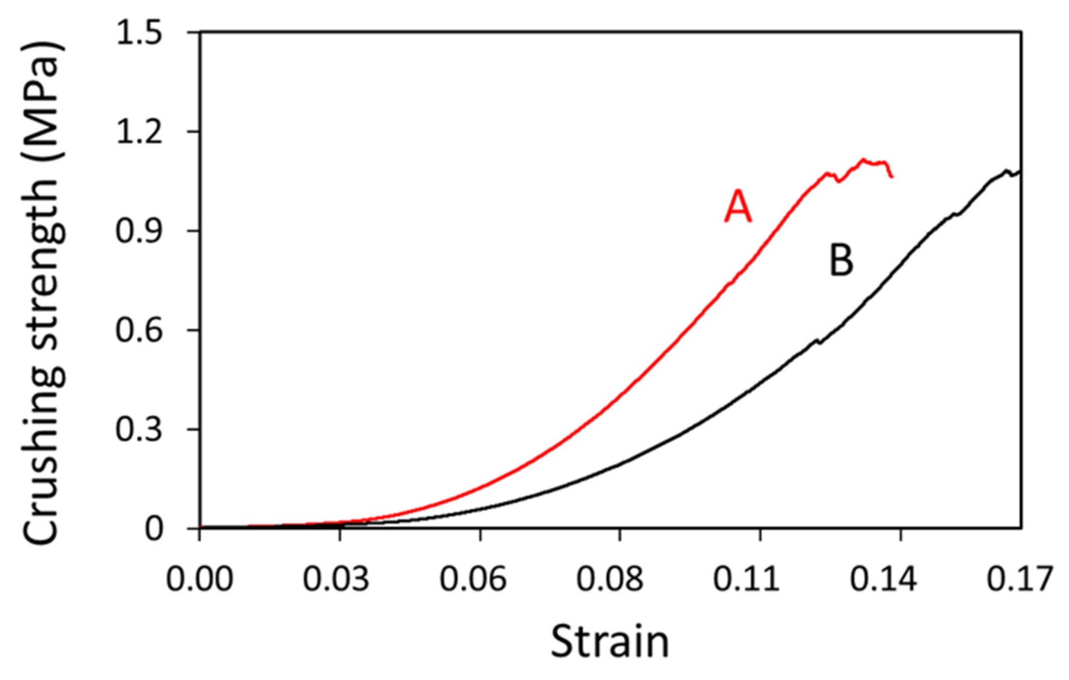
2.4. Crushing Data
3. Discussion
4. Materials and Methods
4.1. Materials
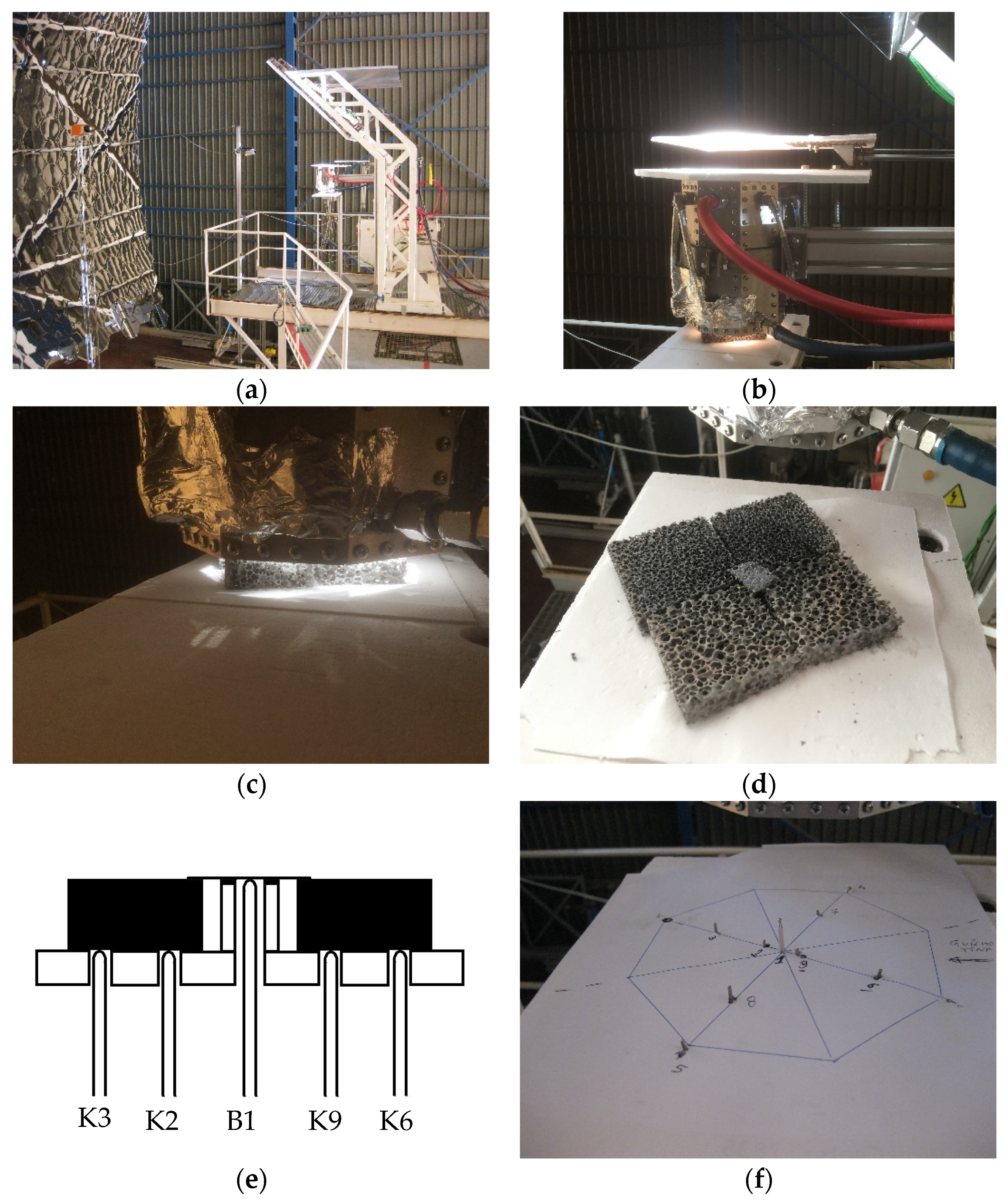
4.2. Thermal Cycling
4.3. Crushing Testing
5. Conclusions
- -
- The ob-SiC RPC foams showed good performance to thermal shock under the conditions investigated;
- -
- The B foam having both lower bulk density and cell size showed better thermal shock behavior;
- -
- Under the most extreme conditions (ΔT = 600 K, 150 cycles), the B foam (20 ppi) showed a crushing strength degradation of nearly half of the A foam (10 ppi) counterparts;
- -
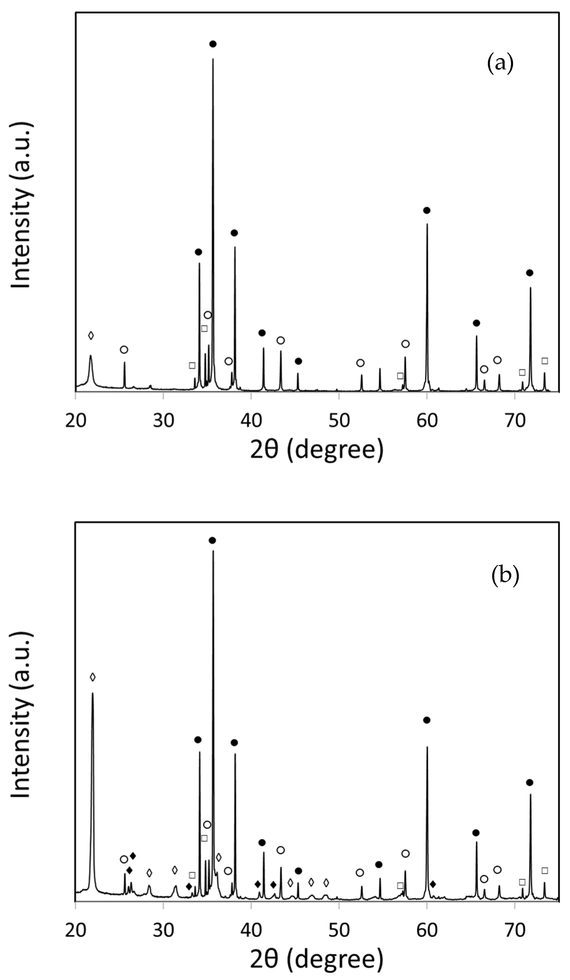
- Exposure of the foams to the thermal cycling resulted in the formation of a SiO2-rich surface layer containing traces of mullite;
- -
- The cooling medium effect on the retained crushing strength was found to be ΔTc = 600 K for A foam;
- -
- The experimental crushing strengths were found to be about double of the predicted by the Gibson-Ashby model, which can be attributed to the fact that outer solid walls are present.
- -
- Future work should focus on evaluating long-term durability, conducting a higher number of thermal cycles, and introducing an air stream during cooling to simulate real appliance conditions.
Author Contributions
Funding
Data Availability Statement
Acknowledgments
Conflicts of Interest
References
- Farjana, S.H.; Huda, N.; Parvez Mahmud, M.A.; Saidur, R. Solar process heat in industrial systems—A global review. Renew. Sust. Energy Rev. 2018, 82 Pt 3, 2270–2286. [Google Scholar] [CrossRef]
- Ravi Kumar, K.; Krishna Chaitanya, N.V.V.; Sendhil Kumar, N. Solar thermal energy technologies and its applications for process heating and power generation—A review. J. Clean. Prod. 2021, 282, 125296. [Google Scholar] [CrossRef]
- Kumar, L.; Ahmed, J.; El Haj Assad, M.; Hasanuzzaman, M. Prospects and challenges of solar thermal for process heating: A comprehensive review. Energies 2022, 15, 8501. [Google Scholar] [CrossRef]
- Aprà, F.M.; Smit, S.; Sterling, R.; Loureiro, T. Overview of the enablers and barriers for a wider deployment of CSP tower technology in Europe. Clean Technol. 2021, 3, 377–394. [Google Scholar] [CrossRef]
- Ávila-Marín, A.L. Volumetric receivers in solar thermal power plants with central receiver system technology: A review. Sol. Energy 2011, 85, 891–910. [Google Scholar] [CrossRef]
- Ho, C.K. Advances in central receivers for concentrating solar applications. Sol. Energy 2017, 152, 38–56. [Google Scholar] [CrossRef]
- Fend, T.; Hoffschmidt, B.; Pitz-Paal, R.; Reutter, O.; Rietbrock, P. Porous materials as open volumetric solar receivers: Experimental determination of thermophysical and heat transfer properties. Energy 2004, 29, 823–833. [Google Scholar] [CrossRef]
- Roldán, M.I.; Smimova, O.; Fend, T.; Casas, J.; Zarza, E. Thermal analysis and design of a volumetric solar absorber depending on the porosity. Renew. Energy 2014, 62, 116–128. [Google Scholar] [CrossRef]
- Wang, F.; Shuai, Y.; Tan, H.; Yu, C. Thermal performance analysis of porous media receiver with concentrated solar irradiation. Int. J. Heat Mass Transf. 2013, 62, 247–254. [Google Scholar] [CrossRef]
- Kribus, A.; Gray, Y.; Grijnevich, M.; Mittelman, G.; Mey-Cloutier, S.; Caliot, C. The promise and challenge of solar volumetric absorbers. Sol. Energy 2014, 110, 463–481. [Google Scholar] [CrossRef]
- Lidor, A.; Fend, T.; Roeb, M.; Sattler, C. Parametric investigation of a volumetric solar receiver-reactor. Sol. Energy 2020, 204, 256–269. [Google Scholar] [CrossRef]
- Hajimirza, S.; Sharadga, H. Learning thermal radiative properties of porous media from engineered geometric features. Int. J. Heat Mass Transf. 2021, 179, 121668. [Google Scholar] [CrossRef]
- Zhao, Y.; Tang, G.H. Monte Carlo study on extinction coefficient of silicon carbide porous media used for solar receiver. Int. J. Heat Mass Transf. 2016, 92, 1061–1065. [Google Scholar] [CrossRef]
- Nimvari, M.E.; Jouybari, N.F.; Esmaili, Q. A new approach to mitigate intense temperature gradients in ceramic foam solar receivers. Renew. Energy 2018, 122, 206–215. [Google Scholar] [CrossRef]
- Patil, V.R.; Kiener, F.; Grylka, A.; Steinfeld, A. Experimental testing of a solar air cavity-receiver with reticulated porous ceramic absorbers for thermal processing at above 1000 °C. Sol. Energy 2021, 214, 72–85. [Google Scholar] [CrossRef]
- Ávila-Marín, A.L.; Caliot, C.; Flamant, G.; Alvarez de Lara, M.; Fernandez-Reche, J. Numerical determination of the heat transfer coefficient for volumetric air receivers with wire meshes. Sol. Energy 2018, 162, 317–329. [Google Scholar] [CrossRef]
- Mey-Cloutier, S.; Caliot, C.; Kribus, A.; Gray, Y.; Flamant, G. Experimental study of ceramic foams used as high temperature volumetric solar absorber. Sol. Energy 2016, 136, 226–235. [Google Scholar] [CrossRef]
- Fey, T.; Betke, U.; Rannabauer, S.; Scheffler, M. Reticulated replica ceramic foams: Processing, functionalization, and characterization. Adv. Eng. Mater. 2017, 19, 1700369. [Google Scholar] [CrossRef]
- Hammel, E.C.; Ighodaro, O.L.-R.; Okoli, O.I. Processing and properties of advanced porous ceramics: An application based review. Ceram. Int. 2014, 40, 15351–15370. [Google Scholar] [CrossRef]
- Lougou, B.G.; Wu, L.; Ma, D.; Geng, B.; Jiang, B.; Han, D.; Zhang, H.; Łapka, P.; Shuai, Y. Efficient conversion of solar energy through a macroporous ceramic receiver coupling heat transfer and thermochemical reactions. Energy 2023, 271, 126989. [Google Scholar] [CrossRef]
- Costa Oliveira, F.A.; Dias, S.; Fernandes, J.C. Thermal shock behaviour of open-cell cordierite foams. Mater. Sci. Forum 2006, 514–516, 764–767. [Google Scholar] [CrossRef]
- Costa Oliveira, F.A.; Fernandes, J.C.; Galindo, J.; Rodríguez, J.; Canãdas, I.; Rosa, L.G. Thermal resistance of solar volumetric absorbers made of mullite, brown alumina and ceria foams under concentrated solar radiation. Sol. Energy Mater Sol. Cells 2019, 194, 121–129. [Google Scholar] [CrossRef]
- Hoffschmidt, B.; Tellez, F.M.; Valverde, A.; Fernandez, J.; Fernandez, V. Performance evaluation of the 200-kWth HiTRec-II open volumetric air receiver. J. Sol. Energy Eng. 2003, 125, 87–94. [Google Scholar] [CrossRef]
- Fend, T.; Pitz-Paal, R.; Reutter, O.; Bauerb, J.; Hoffschmidt, B. Two novel high-porosity materials as volumetric receivers for concentrated solar radiation. Sol. Energy Mater. Sol. Cells 2004, 84, 291–304. [Google Scholar] [CrossRef]
- Behar, O.; Khellaf, A.; Mohammedi, K. A review of studies on central receiver solar thermal power plants. Renew. Sustain. Energy Rev. 2013, 23, 12–39. [Google Scholar] [CrossRef]
- Ávila-Marín, A.L.; Alvarez-Lara, M.; Fernandez-Reche, J. Experimental results of gradual porosity wire mesh absorber for volumetric receivers. Energy Procedia 2014, 49, 275–283. [Google Scholar] [CrossRef]
- Narushima, T.; Goto, T.; Hirai, T.; Iguchi, Y. High-temperature oxidation of silicon carbide and silicon nitride. Mater. Trans. 1997, 38, 821–835. [Google Scholar] [CrossRef]
- Ding, S.; Zhu, S.; Zeng, Y.; Jiang, D. Fabrication of mullite-bonded porous silicon carbide ceramics by in situ reaction bonding. J. Eur. Ceram. Soc. 2007, 27, 2095–2102. [Google Scholar] [CrossRef]
- Costa Oliveira, F.A.; Baxter, D.J. The effect of thermal cycling conditions on oxide scale structure and morphology on a hot-pressed silicon nitride. J. Eur. Ceram. Soc. 1999, 19, 2747–2756. [Google Scholar] [CrossRef]
- Seuba, J.; Deville, S.; Guizard, C.; Stevenson, A.J. Mechanical properties and failure behavior of unidirectional porous ceramics. Sci. Rep. 2016, 6, 24326. [Google Scholar] [CrossRef]
- Gibson, L.G.; Ashby, M.F. Cellular Solids Structure & Properties, 2nd ed.; Cambridge University Press: Cambridge, UK, 1997. [Google Scholar]
- Baitalik, S.; Kayal, N. Thermal shock and chemical corrosion resistance of oxide bonded porous SiC ceramics prepared by infiltration technique. J. Alloys Compd. 2019, 781, 289–301. [Google Scholar] [CrossRef]
- Brezny, R.; Green, D.J. Uniaxial strength behavior of brittle cellular materials. J. Am. Ceram. Soc. 1993, 76, 2185–2192. [Google Scholar] [CrossRef]
- Orenstein, R.M.; Green, D.J. Thermal shock behavior of open-cell ceramic foams. J. Am. Ceram. Soc. 1992, 75, 1899–1905. [Google Scholar] [CrossRef]
- Vedula, V.R.; Green, D.J.; Hellman, J.R. Thermal shock resistance of ceramic foams. J. Am. Ceram. Soc. 1999, 82, 649–656. [Google Scholar] [CrossRef]
- Zaversky, F.; Sánchez, M.; Roldán, M.I.; Ávila-Marín, A.L.; Füssel, A.; Adler, J.; Knoch, M.; Dreitz, A. Experimental evaluation of volumetric solar absorbers—Ceramic foam vs. an innovative rotary disc absorber concept. AIP Conf. Proc. 2018, 2033, 040044. [Google Scholar]
- Rodríguez, J.; Galindo, J.; Cañadas, I.; Monterreal, R.; Fernández-Reche, J. Desing and characterization of the new FAHEX100 concentrator of PSA’s SF60 Solar Furnace. In Proceedings of the SolarPACES 2022, 28th International Conference on Concentrating Solar Power and Chemical Energy Systems, Albuquerque, NM, USA, 27–30 September 2022; Volume 1. [Google Scholar] [CrossRef]
- ASTM C1525-04; Standard Test Method for Determination of Thermal Shock Resistance for Advanced Ceramics by Water Quenching. ASTM International: West Conshohocken, PA, USA, 2004.
- Costa Oliveira, F.A.; Sardinha, M.; Galindo, J.; Rodríguez, J.; Cañadas, I.; Leite, M.; Fernandes, J.C. Manufacturing and thermal shock resistance of 3D-printed porous black zirconia for concentrated solar applications. Crystals 2023, 13, 1323. [Google Scholar] [CrossRef]


| Pore Size (ppi) | Bulk Density 1 (Mg m−3) | Relative Density | Porosity (%) |
|---|---|---|---|
| 10 | 0.46 ± 0.01 | 0.15 | 85 |
| 20 | 0.38 ± 0.01 | 0.13 | 87 |
| (A) | ||||
| Nº. Cycles | ΔT (K) | |||
| 200 | 400 | 500 | 600 | |
| 25 | 0 | 0.04 ± 0.01 | 0.36 ± 0.17 | 1.77 ± 0.65 |
| 100 | 0.28 ± 0.03 | 1.37 ± 0.32 | 2.68 ± 0.39 | |
| 150 | 0.99 ± 0.20 | 1.47 ± 0.06 | 3.30 ± 0.67 | |
| (B) | ||||
| Nº. Cycles | ΔT (K) | |||
| 200 | 400 | 500 | 600 | |
| 25 | 0 | 0.25 ± 0.03 | 0.61 ± 0.08 | 1.23 ± 0.49 |
| 100 | 0.38 ± 0.03 | 1.69 ± 0.51 | 2.26 ± 0.08 | |
| 150 | 0.89 ± 0.05 | 1.72 ± 0.52 | 2.99 ± 0.81 | |
| Foam | Number of Cycles | |||||
| A (10 ppi) | ΔT (K) | 0 | 1 | 25 | 100 | 150 |
| 200 | 0.70 ± 0.01 | |||||
| 400 | 0.59 ± 0.04 | 0.56 ± 0.02 | 0.58 ± 0.01 | |||
| 500 | 0.60 ± 0.02 | 0.55 ± 0.01 | 0.52 ± 0.01 | |||
| 600 | 0.57 ± 0.02 | 0.56 ± 0.02 | 0.53 ± 0.02 | |||
| As-received | 0.70 ± 0.01 | |||||
| 400 (H2O) | 0.52 ± 0.02 | |||||
| 600 (H2O) | 0.50 ± 0.02 | |||||
| Number of Cycles | ||||||
| B (20 ppi) | ΔT (K) | 0 | 1 | 25 | 100 | 150 |
| 200 | 0.67 ± 0.01 | |||||
| 400 | 0.65 ± 0.01 | 0.59 ± 0.07 | 0.60 ± 0.01 | |||
| 500 | 0.64 ± 0.01 | 0.59 ± 0.04 | 0.60 ± 0.04 | |||
| 600 | 0.61 ± 0.02 | 0.58 ± 0.01 | 0.59 ± 0.01 | |||
| As-received | 0.67 ± 0.01 | |||||
| 400 (H2O) | 0.62 ± 0.01 | |||||
| 600 (H2O) | 0.56 ± 0.02 | |||||
| ΔT (°C) | Heating Time (s) | Cooling Time (s) | Number of Cycles | ||
|---|---|---|---|---|---|
| 25 | 100 | 150 | |||
| 800–1000 | 15 | 15 | x | - | - |
| 800–1200 | 35 | 45 | x | x | x |
| 800–1300 | 40 | 45 | x | x | x |
| 800–1400 | 45 | 50 | x | x | x |
Disclaimer/Publisher’s Note: The statements, opinions and data contained in all publications are solely those of the individual author(s) and contributor(s) and not of MDPI and/or the editor(s). MDPI and/or the editor(s) disclaim responsibility for any injury to people or property resulting from any ideas, methods, instructions or products referred to in the content. |
© 2024 by the authors. Licensee MDPI, Basel, Switzerland. This article is an open access article distributed under the terms and conditions of the Creative Commons Attribution (CC BY) license (https://creativecommons.org/licenses/by/4.0/).
Share and Cite
Costa Oliveira, F.d.A.; Galindo, J.; Rodríguez, J.; Cañadas, I.; Cruz Fernandes, J. Thermal Shock Resistance of Commercial Oxide-Bonded Silicon Carbide Reticulated Foams under Concentrated Solar Radiation at PSA: A Feasibility Study. Inorganics 2024, 12, 246. https://doi.org/10.3390/inorganics12090246
Costa Oliveira FdA, Galindo J, Rodríguez J, Cañadas I, Cruz Fernandes J. Thermal Shock Resistance of Commercial Oxide-Bonded Silicon Carbide Reticulated Foams under Concentrated Solar Radiation at PSA: A Feasibility Study. Inorganics. 2024; 12(9):246. https://doi.org/10.3390/inorganics12090246
Chicago/Turabian StyleCosta Oliveira, Fernando de Almeida, José Galindo, José Rodríguez, Inmaculada Cañadas, and Jorge Cruz Fernandes. 2024. "Thermal Shock Resistance of Commercial Oxide-Bonded Silicon Carbide Reticulated Foams under Concentrated Solar Radiation at PSA: A Feasibility Study" Inorganics 12, no. 9: 246. https://doi.org/10.3390/inorganics12090246
APA StyleCosta Oliveira, F. d. A., Galindo, J., Rodríguez, J., Cañadas, I., & Cruz Fernandes, J. (2024). Thermal Shock Resistance of Commercial Oxide-Bonded Silicon Carbide Reticulated Foams under Concentrated Solar Radiation at PSA: A Feasibility Study. Inorganics, 12(9), 246. https://doi.org/10.3390/inorganics12090246