1. Introduction
The wide diffusion of portable electronic devices, electric vehicles (EVs), and energy storage systems required increasingly performing Lithium-Ion Batteries (LIBs). In particular, for the use in EVs, the fast-charging behavior is an almost mandatory request. The large number of LIBs in the market poses, however, many different questions. On the one hand, it is important to deal in the coming years with the problem of the high number of spent batteries and the need for correct and sustainable recycling. Unfortunately, this is still in its early stages because of many obstacles, including science and technology gaps, economic impediments, collection, logistics, and regulatory lacks [
1,
2,
3]. On the other hand, a worldwide known topic is the need to search for substitutes for LIBs due to the reduced reserves and uneven distribution of lithium, as is well explained in plenty of papers [
4,
5].
It is also well established that the most concrete alternative to LIBs is represented by Sodium-Ion Batteries (SIBs) because Na
+ is more abundant and cheaper than Li
+. However, even if similar electrochemical processes are involved, the large ionic radius of Na
+ (Na
+ 1.02 Å; Li
+ 0.76 Å) is the main drawback of SIBs because it hinders a fast ion diffusion in the electrode and causes high volume expansion during intercalation/deintercalation processes [
6,
7,
8]. This issue requires finding new and engineered materials for SIBs, particularly for the anode compartment [
9]. Many materials were proposed as anodes during the last few years, passing from metals to alloys, carbon-based materials, organic-type anode materials, and phosphorus–carbon complexes, each of them functioning with different electrochemical mechanisms [
10,
11,
12,
13,
14]. A large part of the recent research is mainly devoted to hard carbons, which seem very promising for SIBs due to a wide source of precursors, peculiar microstructure, multiple active sites, and low sodium storage potential, even if the mechanism of sodium storage is still controversial. Other possible anode materials are based on the IV group elements either in 2D forms (silicene, germanene) or as alloys [
15,
16]. In particular, those based on germanium have been receiving attention in recent years.
Ge has a limited number of natural minerals that are rare and not widespread on the Earth’s crust [
17]. Between these compounds, Ge-based ternary oxides, in particular, have been recently proposed as anodes for both LIBs and SIBs due to good electrochemical performances allowed by their unique reaction mechanism, i.e., a combination of conversion and alloying [
18,
19]. In LIBs, at the first electrochemical discharge reaction, Ge-based ternary oxides convert to Ge, Li
2O, and the other metals because of an irreversible conversion reaction. The presence of different species limits the expansion of the volume during the electrochemical processes [
20,
21]. In addition, the electronic conductivity could be increased by the second metal, allowing for the improvement in the electrochemical performances. For SIBs, analog mechanisms have been suggested [
22]. However, the performance of the batteries is limited by poor electronic conductivity and volume expansion. In fact, the volume change generates mechanical stress at the base of the detachment of active material from the current collector. Therefore, a short cycling life is obtained, and the bad electrochemical behavior at a high charge/discharge rate is due to the low conductivity of Ge-based ternary oxide.
GeFe
2O
4 (GFO), named brunogeierite, was suggested as an anode for LIBs and SIBs. It has a peculiar story: the identification of the correct cation oxidation states was difficult, and for many years, a lot of uncertainty about them remained. It was then established that the right structure was Ge
4+Fe
2+2O
4 [
17,
23], which differed from the large part of normal spinels having 2+ and 3+ ions in tetrahedral and octahedral sites, respectively.
GeFe
2O
4 can deliver high discharge capacities, but it has poor cycling stability [
22,
24]. Nanostructured engineering, the use of doping ions, and hybrid structures are considered good strategies for overcoming the abovementioned issues. In fact, mechanical stress can be decreased in the case of nanometric particles, which can also abbreviate the paths of ions and electrons, improving the electrochemical performance.
Hybrid structures consisting of active materials and a conductive carbon film are useful for increasing the electrode electronic conductivity and mitigating the active material volume expansion [
25]. However, the use of both strategies to obtain a synergistic effect for improving the electrochemical performances in an electrode is still challenging.
In the few published articles on GFO anodes, their production methods included the hydrothermal method with a carbon coating or the freeze-drying technology [
20,
22,
24]. Other syntheses have been proposed, such as the solid-state one, to synthesize GFO for electrocatalysis or with the aim of determining its physical properties. GFO single crystals have also been obtained [
26,
27,
28]. As discussed, doping for electrode materials could be a strategy to improve their structural stability and increase electron conductivity [
9,
29]. For GFO, up to now, only Mn doping has been reported [
30].
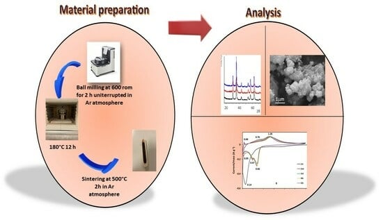
In the present paper, pure and Mg or Sn-doped GeFe2O4 samples have been prepared by an easy mechano-chemical synthesis and tested as anodes in SIBs for the first time, as far as we know. The prepared materials were carbon coated, and the carbon was quantified by thermo gravimetric analysis (TGA) and further investigated by micro-Raman spectroscopy to obtain insights into its order/disorder degree. The purity level has been verified by X-ray powder diffraction, and the main structural parameters have been determined with Rietveld refinement applied to the diffraction patterns; scanning electron microscopy (SEM) was instead used for investigating the morphology. The stoichiometries have been studied by energy dispersive spectroscopy (EDS) and inductively coupled plasma optical emission spectrometer (ICP-OES) measurements. Then, the samples were electrochemically characterized in half-cell configuration by cyclic voltammetry tests and galvanostatic cycling at different C rates. The electrode stability was tested during long-term cycling for 120 cycles at 0.2 C.
2. Materials and Methods
GeFe
2O
4 and Ge
0.95M
0.05Fe
2O
4 (M = Sn or Mg) samples have been obtained by a mechano-chemical solid-state synthesis via ball-milling [
27], starting from Fe (Sigma-Aldrich, Saint Louis, MO, USA max 60 μm), Fe
2O
3 (Sigma-Aldrich, nanopowder < 50 μm), GeO
2 (Sigma-Aldrich, >99.99%) and, in case of doping, SnO
2 (Sigma-Aldrich, 99+%) or MgO (Sigma-Aldrich, >97%). Before the synthesis, Fe was grounded alone via ball milling in WC jars and balls at 300 rpm for 1 h to obtain smaller grain sizes. The proper amount of the reagents was subsequently mixed in a mortar and transferred in WC jars with WC balls (powder to balls ratio 1:30) that were closed in a dry box under an Ar atmosphere. Then, they were ball milled in a Fritsch Pulverisette 7 (Fritsch GmbH, Idar-Oberstein, Germany) ball milling apparatus at 600 rpm for 2 h uninterrupted.
A hydrothermal method was chosen to produce the carbon coating of the samples. An amount of 0.4 g of pure or doped GFO was dispersed in a glucosamine aqueous solution (0.8 g in 60 mL) via sonication. The dispersion so obtained was transferred into an autoclave and heated in a muffle at 140 °C for 12 h. The samples were collected by centrifugation, washed twice with water and once with ethanol, then dried at 80 °C overnight. Finally, the powders were calcinated at 500 °C for 2 h in an argon atmosphere to realize the carbon layer. In the following sections, the acronyms GFO, GFO-Sn, and GFO-Mg will be used for GeFe2O4, Ge0.95Sn0.05Fe2O4, and Ge0.95Mg0.05Fe2O4 samples, respectively, and acronyms GFO-C, GFO-Sn-C, and GFO-Mg-C will be used for the compounds covered with carbon.
X-ray powder diffraction (XRD) measurements were collected on a Bruker D5005 diffractometer (Karlsruhe, Germany) via CuKα radiation. The experimental conditions were 17–110°, a step size of 0.03°, and 15 s/step of counting time. Rietveld method (TOPAS3.0 software) was used to perform the structural refinement by using the known structural model of the GeFe2O4 cubic spinel phase. Lattice parameters, crystallite sizes, zero error, background coefficients, oxygen coordinates, occupancies, and thermal factors have been varied. Proper constraints have been used to determine the occupancies, i.e., the maximum value for the occupancy have been set to the unit (the complete site occupation), to avoid negative values.
A Zeiss EVO MA10 (Carl Zeiss, Oberkochen, Germany) microscope coupled with an EDS detector (X-max 50 mm, Oxford Instruments, Oxford, UK) was employed to perform Scanning Electron Microscopy (SEM) and microanalysis (EDS) measurements. The samples were gold-sputtered for the SEM, while they were used as loose powders for the EDS measurements.
Element measurements were carried out by a Thermo-Fisher iCAP 7400 inductively coupled plasma-optical emission spectrometer (Thermo Fischer Scientific, Waltham, MA, USA) equipped with a cyclonic spray chamber, a concentric nebulizer, and a ceramic duo-torch, according to the operating conditions suggested by the manufacturer. Small amounts, exactly weighted, of each sample were digested with a few milliliters of different acid mixtures (ultrapure 65% HNO3 and ultrapure 37% HCl, ultrapure 65% HNO3 and ultrapure 47–51% HF) and gently heated. The obtained solutions were first diluted to 40 mL with ultrapure water and then to 10 mL before ICP-OES measurements.
Thermo-Gravimetric Analysis (TGA) and Differential Scanning Calorimetry (DSC) were performed with an SDT Q600 TA simultaneous instrument (TA Instruments, New Castle, DE, USA). All the measurements were carried out in an air atmosphere (heating rate 10 °C/min) in the temperature range 20–750 °C.
An automated XploRA Plus HORIBA Scientific (Osaka, Japan) equipped with an Olympus (Tokyo, Japan) microscope BX43 confocal micro-Raman spectrometer was used to perform Raman measurements at room temperature, with a spectral resolution of about 1 cm−1. The incident laser power was set using neutral filters with different optical densities. The samples were positioned on a motorized XY stage. The detector was an Open Electrode CCD camera with a multistage Peltier air cooling system. A 638 nm (90 mW) laser source was employed for the measurements, using a 50x magnification objective (spot size of about 4 μm2). The laser power density on the samples was about 2.5 × 10⁴ W/cm2. An integration time of 10 s and a number of accumulations of 10 were used to record the spectra in different areas of the samples. The shown spectra are the average of the collected ones.
Electrodes were produced by mixing 70 wt% of the active material with 20 wt% of carbon (Super C65, Imerys, Paris, France) in water and 10 wt% of Sodium Carboxymethylcellulose (Na-CMC) as binder. The slurries were coated on an aluminum carbon-coated foil with a homemade doctor blade; then, they were kept overnight at room temperature and dried at 60 °C for 6 h in a vacuum oven. The electrodes were then hot pressed and cut in discs (mass loading of about 1.5 mg/cm2) before being used as anodes in Swagelok test cells assembled in an argon-filled dry box (MBraun, Garching bei München, Germany; O2 < 1 ppm, H2O < 1 ppm). Na metal was the reference and counter electrode, while a Whatman GF/D membrane was the separator. As an electrolyte, a 1 M NaPF6 in a mixture of ethylene carbonate (EC)/diethyl carbonate (DEC) (1:1 by volume) was employed.
Cyclic voltammetry (CV) measurements were carried out between 0.01 V and 3 V for five cycles (scan rate 0.1 mV/s) using an Autolab PGSTAT30 (Eco Chemie, Metrohm, Utrecht, The Netherlands). Na insertion/deinsertion mechanism (diffusive or pseudo-capacitive) was determined by cycling the half-cells at 0.1 mV/s for 3 cycles, then at 0.2, 0.5, 0.7, and 1.0 mV/s for one cycle. The Galvanostatic charge and discharge tests were performed in the 0.01–3 V potential range between 0.1 C and 2 C with a Neware (Hong Kong, China) Battery Test System. Long-term cycling stability was evaluated for all the electrodes at 0.2 C for about 120 cycles.
3. Results and Discussion
3.1. XRD and Rietveld Refinement
As previously explained, doping could be a winning approach to improve the electrochemical performances of electrode materials. In the literature, there is only one paper reporting the effect of doping on GFO samples obtained from hydrothermal synthesis, in particular, the Mn doping on Fe crystallographic sites [
30]. In the current case, doping was supposed to occur on Ge sites, and the dopants were chosen with two different aims. Sn, having the same valence state as Ge and similar physical–chemical characteristics, could easily substitute germanium and possibly provide an increase in capacity values because it is an active redox species and, as is well known, the capacities provided by Sn and its compounds in SIBs can be higher than those of the corresponding Ge-based compounds [
31]. In fact, SnFe
2O
4 is a spinel phase proposed for use in LIBs that can provide interesting capacity values [
32]. Mg ions, such as Sn, should have complete solubility in the spinel structure and can provide an increase in structural stability, particularly useful for long-term cycling, as reported for other kinds of anode materials [
33,
34]. In addition, due to the lower oxidation state of Mg (2+), with respect to Ge (4+), the formation of oxygen vacancies cannot be excluded, possibly improving the Na
+ diffusion.
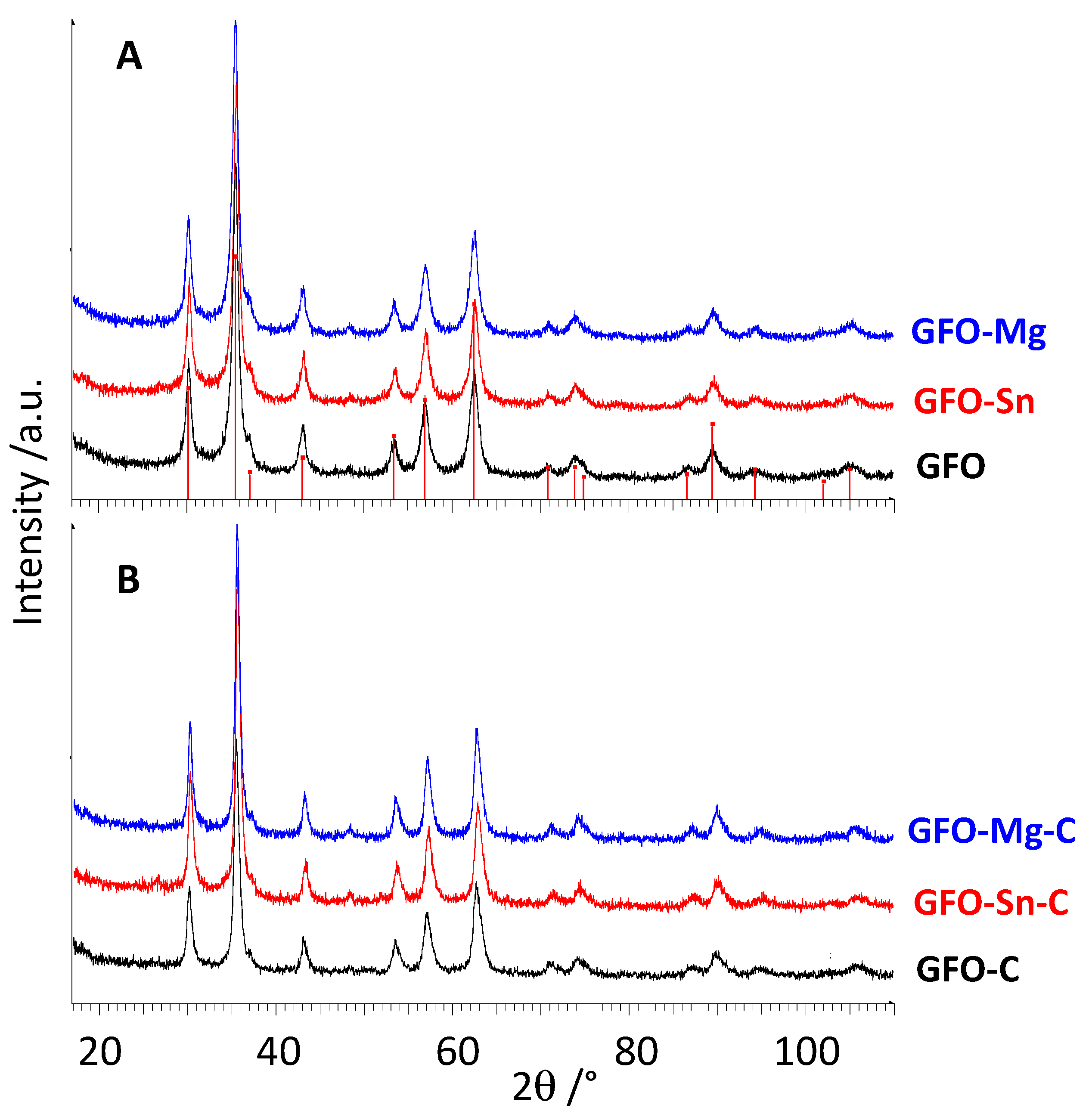
Figure 1A,B shows XRD patterns of pure and doped GFO samples before and after carbon coating, respectively.
All the peaks of the XRD patterns are well explained with the expected peak positions of cubic GeFe
2O
4 spinel (card N. 25-0359) (
Figure 1A). The doping does not cause significant changes either in peak positions or in the peak intensities and broadening. Due to the absence of crystalline phases containing the dopant, a complete solubility of Sn and Mg ions in the GeFe
2O
4 cubic structure, at least for the chosen amount, can be supposed. On the other hand, Mg ions can form a well-known and studied spinel phase, i.e., MgFe
2O
4 and Sn has many similarities with Ge, so justifying the ease of substitution. The carbon-coated samples are over-imposable between them and to the corresponding uncoated samples (
Figure 1B), suggesting that the coating does not change the spinel structure as expected and, due to the absence of peaks of graphite, that the carbon is in an amorphous state. From the pattern’s inspection (
Figure 1B), a slightly higher crystallinity degree for coated samples can be expected even if the materials are still nanosized, probably due to the additional hydrothermal treatment performed to obtain the coating.
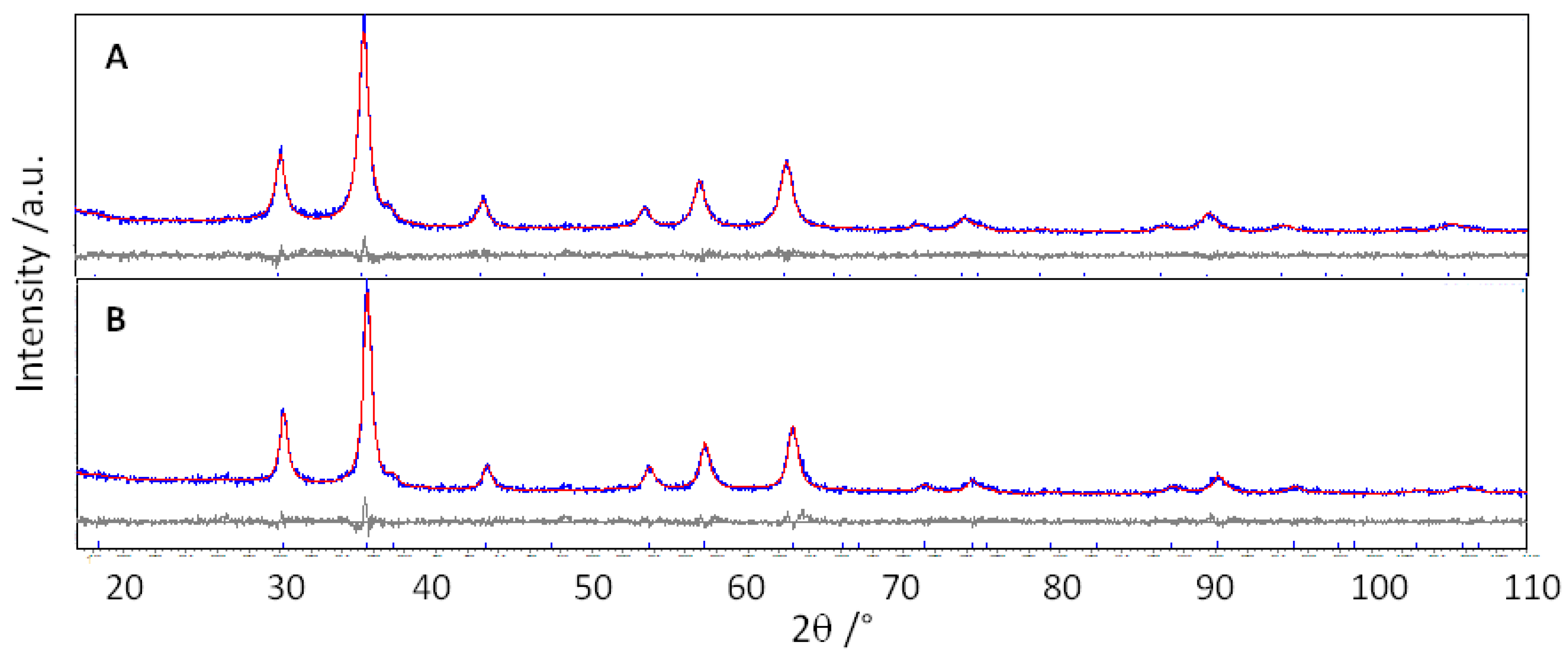
The Rietveld refinements have been performed to determine the main structural parameters, starting from the known structural model of GeFe
2O
4. In
Table 1, the main structural parameters are reported, and in
Figure 2, as an example, the experimental and calculated patterns of GFO-Sn and GFO-Sn-C samples are compared.
A good graphical agreement between the experimental and calculated patterns is evident, suggesting the reliability of the refinements, as also indicated by the agreement indices values (
Table 1, GoF near 1).
Pure and doped samples present similar lattice parameters that are analogous to the values reported in the literature for the same material [
22,
24]. The parameters of the carbon-coated samples instead slightly decrease (0.4–0.65%) with respect to the corresponding uncoated ones. A similar effect seems present for a GFO sample reported in the literature [
22]. Two different reasons for the lattice parameters’ decrease could be hypothesized: (i) the formation of some amount of Fe
3+ after the carbonization process, having a lower ionic radius with respect to Fe
2+; or (ii) oxygen vacancies formation. Due to the tendency to oxidation of iron and the easy formation of a solid solution of brunogeierite and magnetite [
17], the first hypothesis seems the most conceivable, as also suggested by the observation of the oxygen coordinate values (
Table 1). It is evident that passing from undoped to doped samples, the values increase, addressing x = 0.25, occurring for an ideal cubic structure. Due to the electronic configuration of Fe
3+ and Fe
2+ ions, more regular octahedral coordination is expected for Fe
3+, possibly explaining the small increase in the oxygen coordinate.
The crystallite size values are typical of nanometric materials, as expected for ball-milled powders. The carbon-coated samples have slightly greater sizes, as speculated also from the patterns’ inspection (
Figure 1), due to the additional thermal treatment performed to produce the carbon coating.
The site occupancies can be reliably determined by the Rietveld refinement due to the different atomic scattering factors of X-rays of the involved atoms, allowing us to verify the sample stoichiometries. As also stated in the experimental part, proper constraints were used to fix the sum of Ge+M on the tetrahedral site to 1, the maximum occupancy. In all the cases, the 5% atomic substitution corresponding to the stoichiometric value has been confirmed within the standard deviations (
Table 1).
3.2. TGA and Micro-Raman Results
TG-DSC combined analysis was performed to determine the carbon amount for the different samples, and the results are reported in
Figure S1: an amount of about 14–16 wt% of carbon was found for all the samples. In the curves, it has been observed that an initial small mass loss was associated with adsorbed water, followed by a slight increase in weight at about 250 °C, suggesting the possible oxidation process of Fe
2+ during the heat treatment. Then, a huge decrease in weight at about 300 °C can be explained by carbon loss in the form of CO
2: this is, in fact, a highly exothermic and rapid process, as suggested by the heat flow values and, at least for GFO-C and GFO-Mg-C, also by the form of the TGA curve (see
Figure S1A,C).
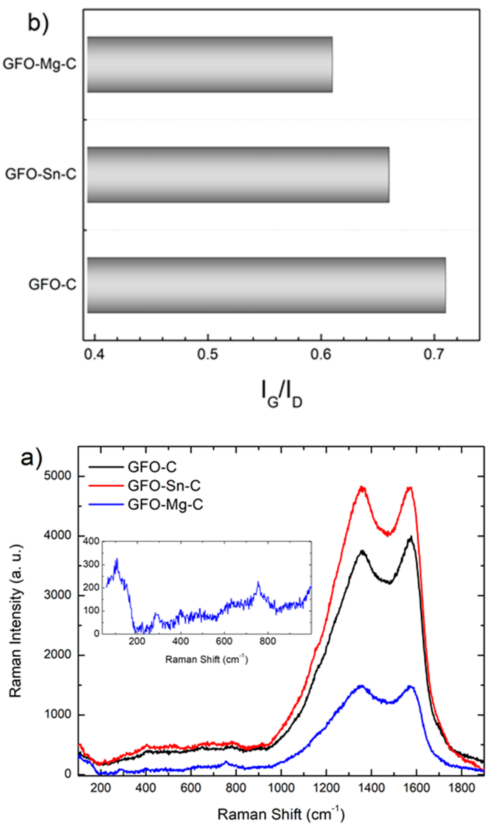
The carbon coating was further analyzed using a micro-Raman investigation.
Figure 3a reports the Raman signals of the carbon-coated samples in the range between 100 cm
−1 and 1900 cm
−1. At first, as highlighted in the inset for the GFO-Mg-C sample, Raman features typical of the brunogeierite phase could be observed in the low region of the spectra: three sharp modes at about 290, 400, and 760 cm
−1 and a wider band centered at 640 cm
−1 [
28].
The main Raman activity in all the three investigated samples falls in the higher energy portion of the spectrum, characterized by two broadened bands peaked at around 1370 and 1570 cm−1, pertinent to the carbon cages activity. Indeed, the mode at 1570 cm−1 is called the G band, and it is characteristic of an ordered sp2 graphitic-like network. The mode at 1370 cm−1, known as the D band, is undoubtedly attributed to the structural disorder even if the source of the disorder is different, i.e., sp3 hybridized amorphization, structural defects, edge effects, and symmetry-breaking dangling sp2 carbon bonds.
The intensity ratio between G and D bands provides an indication of the quality of the carbon matrix. The IG/ID ratio was derived by performing a best-fitting procedure by the sum of a Lorentzian curve accounting for the G-mode and a Gaussian curve for the D mode. The obtained values (
Figure 3b) seem to suggest that the presence of a dopant introduces further disorder in the carbonaceous matrix if compared to the pure sample.
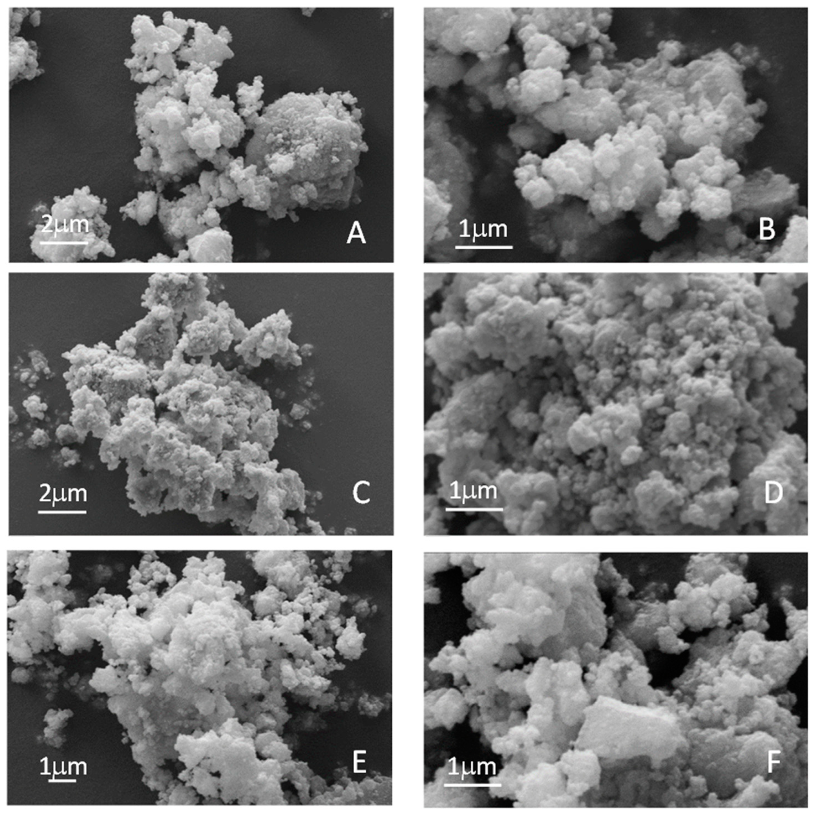
3.3. Morphological Analysis
The sample’s morphology and the possible changes introduced by the dopants have been investigated by SEM (
Figure 4).
All the samples shared the same morphologies, constituted by aggregates of smaller spherical particles. No changes seem to have been introduced by the doping, as could be expected due to the same synthesis route and the high solubility of the dopants in the cubic cells, as also demonstrated by XRD (
Figure 1).
The EDS results about the chemical compositions of the samples are shown in
Table 2.
In all the cases, a good agreement between the expected and the detected stoichiometries is found. The Fe/Ge ratios are near to the stoichiometric ones, as well as the Sn/Ge ratio. The Mg/Ge ratio, unfortunately, cannot be detected by EDS because the energies of MgKα and GeLα are similar, and their peaks are completely overlapped. Thus, ICP-OES measurements were performed after acid digestion of the samples to determine the Mg stoichiometric amount (80%) and to confirm the stoichiometric amount of the other elements (Ge 97%, Fe 93%, Sn 86%, RSD% ≤ 10%; n = 3) determined by EDS.
3.4. Electrochemical Characterization
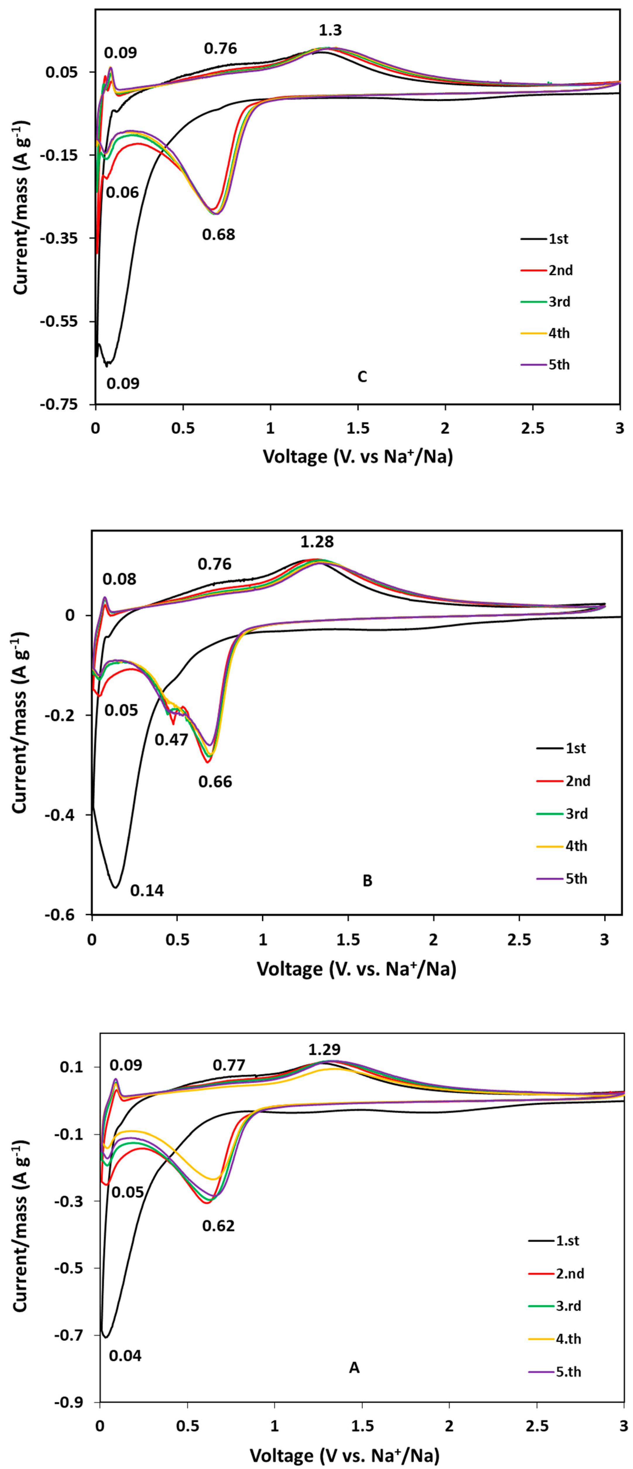
Cyclic voltammograms of the carbon-coated samples are shown in
Figure 5.
The electrochemical reactions for GeFe
2O
4 are the same accepted worldwide for the spinels applied in the battery field, i.e., conversion and alloying combined mechanism [
35,
36]:
For the GFO-C sample (
Figure 5A), in the reduction scan of the first cycle, a broad peak near 0 V is attributed to the irreversible reaction of GeFe
2O
4 to amorphous Ge and Fe metallic particles embedded in Na
2O matrix (Equation (1)), followed by the alloying process of Ge with sodium (Equation (2)). In the first anodic scan, instead, the two-step oxidation reaction of Fe to Fe
2+ and Fe
3+ is highlighted by the two oxidation peaks at about 0.77 V and 1.3 V, respectively [
22]. Starting from the second cycle, the cathodic peak at about 0.6 V is related to the reduction of Fe
3+ to metallic Fe, following the conversion reaction (Equation (3)) represented by the anodic peak at about 1.3 V. In addition, the reduction peak at about 0.03 V can be associated with the Ge dealloying process. From the third to the fifth cycle, the curves are well-reproducible, suggesting that the electrochemical processes are well-reversible.
The voltammograms of the doped samples are similar to those of pure ones, indicating the same redox phenomena and similar process reversibility. For the GFO-Sn-C sample (
Figure 5B), it could be better appreciated in the cathodic scan the peak due to the alloying process (at about 0.5 V) that is well separated from the peak corresponding to the reduction of Fe
3+ to Fe
0 (0.7 V), while for the other samples, only a broad peak could be observed. This evidence can also be due to the contribution of Sn to the alloying phenomenon with Na.
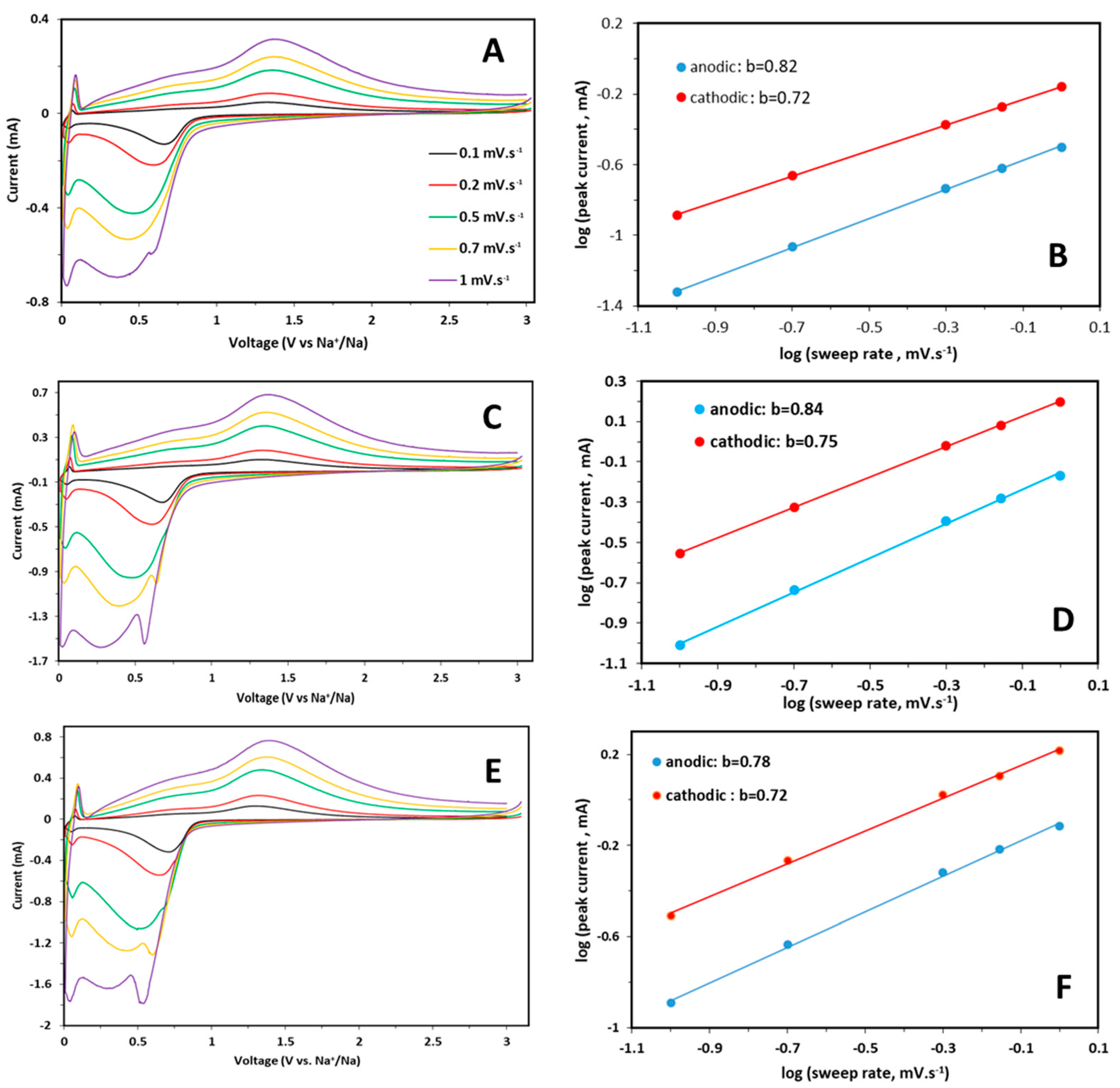
CV curves were also collected for each sample at scan rates from 0.1 to 1.0 mV s
−1, as shown in
Figure 6A,C,E.
An increase in the peak intensity and broadening with a limited shift of redox peaks is observed for each sample by increasing the sweep rate, suggesting an intrinsic pseudo-capacitive behavior. It is known that the relationship between peak current and sweep rates can provide information about the characteristics of an electrochemical reaction, i.e., if the process is mainly solid phase, diffusion-controlled, or surface-confined charge transfer. The pseudocapacitive contribution for each sample was calculated starting from the relation Ip = av
b, where a and b are variable parameters: b = 1 denotes 100% capacitive behavior, whereas b = 0.5 reveals 100% diffusion-controlled behavior [
37]. The equation can be written as log Ip = log a + b log v to determine the b parameter. These plots are reported in
Figure 6B,D,F for pure and doped samples. The obtained b values, are slightly higher for the anodic part, suggest a predominant capacitive effect in the electrochemical processes for all the samples. The increasing scan rate causes a peculiar behavior: the separation of the broad peak of the cathodic scan in two separated contributions, that is more evident for doped samples than for pure one. It can be suggested that this new peak is related to an obvious diffusion-controlled process, whereas the lower peak at about 0.25 V indicates a pseudocapacitive contribution due to a faradaic reaction, as suggested by the b value (
Figure 6). The performances at high C rates can be influenced by the capacitive contribution, while the diffusive one, more evident in the doped samples, could provide better performances at low C rates.
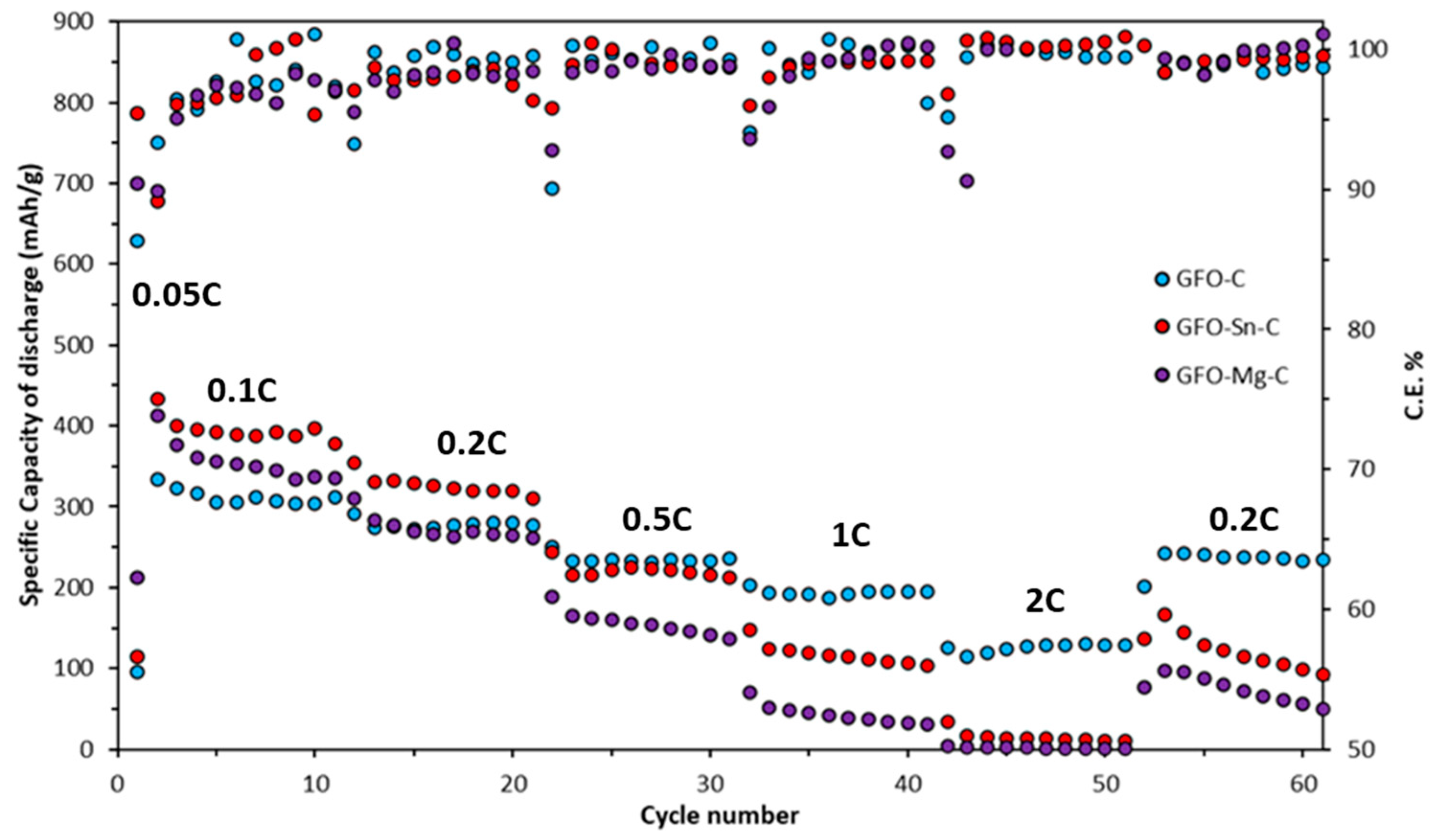
The voltage profiles at the fourth cycle at different C rates are reported in
Figure S2, and the galvanostatic cycling at various C rates is shown in
Figure 7.
The voltage profiles of all the samples show a plateau at approximately 0.6 V, ascribed to the irreversible decomposition reaction of GeFe
2O
4 into its individual components during the first discharge at C/20. For the subsequent fourth cycles at different C rates, the other two plateaus can be observed at ~1.6 V and ~0.6 V, respectively, which are in good agreement with the peaks of the CV curves (
Figure 5). It can be noted that the curves are gradually shifted by switching the C rate at lower capacity values, as is also evident in the rate capability tests (
Figure 7).
However, good performances are provided by all the samples (
Figure 7): the doped ones outperform the pure GFO at low currents (up to about 0.5 C, at least for the GFO-Sn-C). This can be due to the prevalence of the diffusive component for the redox process, as evidenced by the CV at different scan rates (see
Figure 6). All the samples in the first conditioning cycle at 0.05 C showed capacity values between 700 and 790 mAh/g. Passing to 0.1 C, the capacity decreases to values between 312 and 396 mAh/g, depending on the sample. This is due to irreversible phenomena, such as the spinel decomposition and the SEI formation. The highest capacity is provided by the GFO-Sn-C sample, with about 396 mAh/g at 0.1 C, followed by GFO-Mg-C with 355 mAh/g and the GFO-C with 312 mAh/g. In all the cases, the capacities tend to decrease by increasing the C rate; however, at 1C, values of about 193 and 114 mAh/g are again provided by GFO-C and GFO-Sn-C samples, respectively. At 2 C, the pure sample has capacity values higher than 100 mAh/g, while the doped ones have values near zero. By returning to 0.2 C, the GFO-C sample recovers the initial capacities, while both doped samples reach lower values, suggesting some structural instability. The Coulombic efficiencies are good for all the samples, near 97–98%, at least up to 1 C, apart from GFO-Mg with the lowest values (about 97% and 94% at 0.5 C and 1 C, respectively). At 2 C and after the return to 0.5 C, only the GFO-C has good values, near 100%.
On the base of the galvanostatic cycling, some observations can be made. The doping, in general, both with Sn and Mg, seems useful for the improvement in the capacity values: at 0.1 C increase of about 26 and 14% and 18% and 13% at 0.2 C for GFO-Sn-C and GFO-Mg-C, with respect to the pure GFO-C are observed. The best performances are presented by the Sn-doped sample. This behavior could have been expected because tin is an element that is able to alloy with 15 sodium ions compared to germanium, providing additional capacity. The capacity values are stable at the different C rates, suggesting a reversible sodiation–desodiation process, apart from when the current returns to 0.2 C, and a decreasing trend of the capacity is evident. This could be due to a not sufficiently optimized structure and/or morphology. For the improvement in performance, it will be necessary to optimize the carbon layer, which should help to increase the electronic conductivity and should be sufficiently porous to buffer the volume expansion and favor the electrolyte permeation. A strong bond between the carbon layer and ferrite nanoparticles could help to better accommodate the volume expansion and provide stability during cycling. This is particularly true for performances at a high C rate when the pseudocapacitive behavior should prevail on the diffusive one. To this aim, the morphology of the native GFO particles could also be better tuned. We recall that the samples were produced by a mechanochemical synthesis, and some aggregation was evidenced from SEM images. Another strategy could be the variation in the dopant amount to find a proper value that could help to further increase the capacities and improve the structural stability. The tested amount was low, but we could expect that a higher dopant amount could be accommodated in the spinel structure due to the complete solubility of the chosen dopants in this kind of structure (as previously explained).
To better explain the GCPL results, the diffusion coefficients (D) were estimated using the Randles–Servick equation, and the results are reported in
Table 3.
The values are in line with those reported for other electrode oxide materials [
38,
39]. There is an evident improvement in the D values of the doped samples with respect to the pure in a more evident way for the sodiation with respect to the desodiation process. The doping was helpful for the improvement in sodium diffusion, explaining the high-capacity values, particularly at a low C rate.
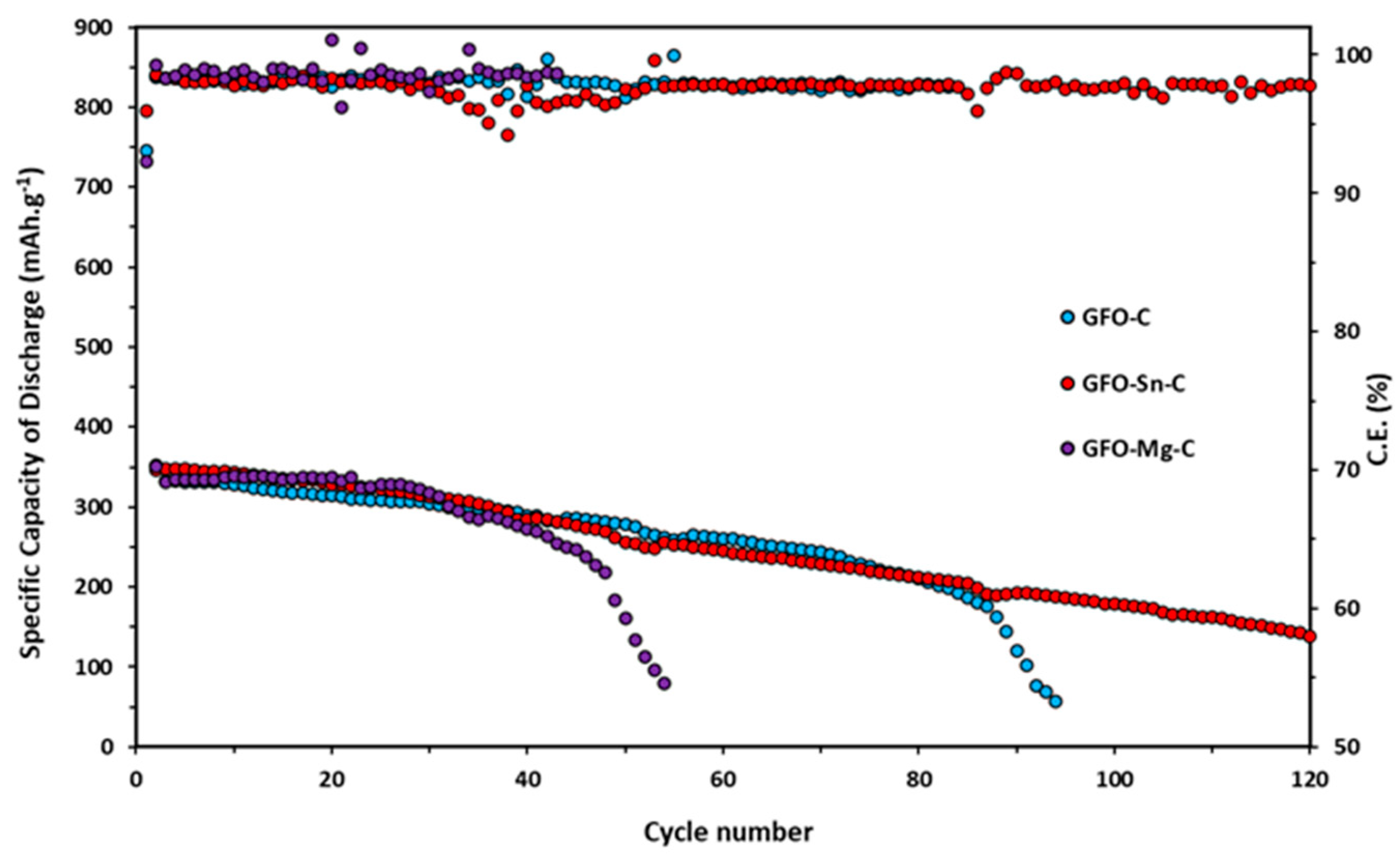
Long-term cycling tests at 0.2 C for all the samples are reported in
Figure 8.
Doped samples exhibit slightly higher initial specific discharge capacity (345 mAh/g for GFO-Sn@C and 336 mAh/g for GFO-Mg@C) in the first ten cycles compared to the undoped one (331 mAh/g). However, these values tend to decrease during cycling: the GFO-Mg-C sample stops working after about 50 cycles, and the GFO-C—after about 90 cycles. The sample with the best performance is the Sn-doped sample, which, after 120 cycles, even if with a decreasing trend, provides a capacity value of about 180 mAh/g. The coulombic efficiency of GFO-C and GFO-Sn-C is very good, near 100%. These results confirm those obtained from the cycling at the different C rates and strengthen the conviction that the performances could be improved with a properly optimized carbon coating.


 ,
, 


