Article

Numerical Analysis of a High-Velocity Projectile’s Impact on Shallow Steel Tunnels in Soft Sandstone

1
Graduate School of Engineering, Hokkaido University, Sapporo 060-8628, Japan
2
Department of Civil Engineering, Indian Institute of Technology Kharagpur, Kharagpur 721302, India
3
Department of Civil Engineering, Indian Institute of Technology Delhi, New Delhi 110016, India
*
Author to whom correspondence should be addressed.
Infrastructures 2024, 9(3), 49; https://doi.org/10.3390/infrastructures9030049
Submission received: 19 December 2023 / Revised: 24 January 2024 / Accepted: 2 March 2024 / Published: 4 March 2024
(This article belongs to the Special Issue Geotechnical Earthquake Engineering)

Abstract

:
Tunnels are underground infrastructures intended for diverse community applications as well as military applications. During impact loading due to high-velocity projectiles such as ballistic missiles, materials experience a high strain rate. Moreover, there is a superficial augmentation of the dynamic strength when geomaterials such as rock are subjected to a high strain rate. Despite this strength enhancement, tunnels can get damaged by the impact load of a projectile hitting at a high velocity if they are present at a shallow depth. The present study is an effort to comprehend the response of a shallow tunnel in soft sandstone due to the impact load by a ballistic projectile using the FEM-based software ABAQUS/CAE 6.11. The Drucker–Prager damage model and the Johnson–Cook damage model were used to define the properties of the rock mass and steel tunnel lining, respectively. The crown of the 3 m diameter tunnel was kept at different depths from 1 m to 5 m from the surface. A striking velocity of 1000 m/s at a normal position to the target was given to the projectile. The projectile caused noticeable damage to the tunnel lining up to 3 m crown depth. Increasing the crown depth had a positive effect on the maximum depth of the projectile penetration up to 4 m tunnel crown depth, after which the effect reversed, making the tunnel safer. The maximum von Mises stress on the tunnel lining reduced in a logarithmic trend with an increase in the crown depth, gradually lowering to an impact load lesser than the yield stress of the tunnel lining material after a crown depth of 4.5 m.

1. Introduction

Tunnels are underground infrastructures or geostructures intended for diverse community applications such as transportation, conveyance of cables (electricity, telephone), sewers, recreation, etc., as well as military applications such as strategic defense, storage, etc. Tunnels are considered shallow when the tunnel crown is close to the ground surface [1]. Ballistic threats are those that intend to damage the target by penetration (e.g., missile), striking at a high velocity. The possibility of damage to a buried structure by such a round depends on its ability to penetrate overlying soil or rock [2]. Zukas [3] categorized ballistic threats into kinetic energy threats (small armor projectiles, high caliber rounds) and chemical energy threats (shaped charges, explosively formed projectiles). Shallow tunnels at risk of kinetic energy threats such as high-velocity ballistic missiles, during emergency situations such as war, terrorist attack, etc., will be subjected to impact load during the strike, affecting the stability of the tunnel. It is also possible to blast inside a tunnel after penetrating it during such an event by applying chemical energy threats [4].
Impact load is a class of non-periodic dynamic loads applied for a short duration of time [5]. Dynamic events such as impact and blast are characterized by transient responses in terms of stress and strain states. The duration of the event plays a significant role in these processes. As the duration of the event gets smaller (i.e., increasing strain rate), the response of the material diverges from the quasi-static behavior to dynamic equilibrium [3].
Materials experiencing impact load undergo a high strain rate, and geomaterials such as rock and concrete subjected to a high strain rate show a superficial augmentation in dynamic strength [6]. Therefore, the dynamic strength increase in geomaterials has drawn enormous concern in structural design under impact loading conditions. Taking into account the dynamic strength variations of geomaterials when designing structures subjected to impact loading conditions can enhance safety and cost-effectiveness. However, despite this strength improvement, shallow underground structures may still be vulnerable to damage from the impact force of a high-speed ballistic projectile. Therefore, it is essential to evaluate the optimum tunnel crown depth for the safety of a shallow tunnel subjected to impact load.
Examples of experimental, analytical, and numerical studies related to impact loading on different materials (metals, concrete, soil, rock, and rubber) individually can be found in the literature, although these studies conducted in the past related to impact loading on metals and geomaterials separately [7,8,9,10,11,12,13,14,15,16,17,18,19,20,21,22,23]. At present, there is a rise in experimental and numerical studies associated with tunnels subjected to impact loading [4,24,25,26,27,28,29,30,31,32,33]. However, these studies are mostly related to the study of crack propagation, deformation on the tunnel lining, and rock mass properties. Therefore, literature related to the influence of crown depth on the impact load on such geo-structures is not yet extensive.
The availability of sophisticated software and high-speed computers has made it easier to interpret complex rock mass behavior with the help of numerical modeling. The numerical methods in rock engineering are classified either as continuum or as discontinuum. A continuum model, as the name suggests, can be used for numerical analysis when there is enough evidence that the actual physical system of the rock mass can be represented in a continuum. Continuum models will be representative only if the rock mass in the field conditions acts like a continuum, i.e., only a few fractures or joints are present in the system. FEM is a numerical modeling technique based on continuum models.
The FEM approach involves dividing a complex region into discrete elements that are represented by simple geometric shapes. Mathematical equations express the properties and governing relationships of the elements, with unknown values at specific points known as nodes. These individual elements are then linked together using an assembly process to form the complete system. Load and boundary conditions are taken into account to obtain a set of linear or non-linear algebraic equations. The solution of these equations yields an approximate representation of the system’s behavior. The stress–strain behavior of the elements is approximated by constitutive relationships. FEM is the first numerical method with enough flexibility for the treatment of material heterogeneity and non-linear deformability, mainly plasticity. Among the various software packages available for numerical modeling, ABAQUS/CAE does not have predefined material properties, and thus, it can be defined independently. For this reason, ABAQUS/CAE was selected for use in this study. Preprocessing, simulation, and postprocessing are the three major components of a complete ABAQUS analysis (Figure 1). Preprocessing involves defining the model of the physical problem and creating the input file. The simulation stage runs in the background, solving the problem; postprocessing involves the display and evaluation of the results in a suitable viewer.
The present study is an effort to comprehend the response of shallow steel tunnels in soft sandstone due to the impact load by a ballistic projectile using FEM-based software ABAQUS/CAE 6.11. A 3 m diameter tunnel with the crown placed at different depths (from 1 m up to 5 m) from the rock surface. A striking velocity of 1000 m/s at a normal position to the target was given to the non-deformable projectile. The depth of penetration, velocity of the projectile, and impact load/von Mises stress on the tunnel lining corresponding to different crown depths were evaluated.

2. Methodology

2.1. Geometric Properties

The geometry of the projectile, tunnel lining, and surrounding rock were created in their local coordinates in the part module. The part module allowed us to create, edit, manage the parts, define features (e.g., solids, shells, rounds, etc.), and add reference points to a rigid part.

2.1.1. Projectile Geometry

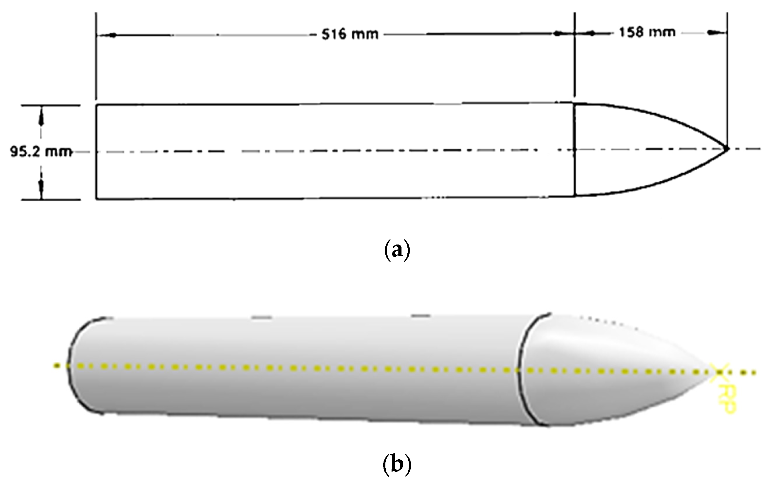
A solid, non-deformable steel projectile, as shown in Figure 2, was modelled with a single node reference point to assign mass and initial velocity for the analysis. A striking velocity of 1000 m/s at a normal position to the target was assigned to the projectile.

2.1.2. Tunnel and Surrounding Rock Geometry

Steel tunnels in soft sandstone were considered with different crown depths from 1 m to 5 m below the overburden rock. The tunnel lining material was considered to be 50 mm thick steel. The tunnel section was considered to be 3 m in diameter. The vertical side boundaries of the soft sandstone were kept at a 2 m distance from the tunnel center. The upper half part of the tunnel and surrounding rock assembly were considered for the analysis. A schematic of the tunnel at 1 m crown depth with the surrounding rock mass is shown in Figure 3.

2.2. Material Properties

2.2.1. Constitutive Damage Models

The Drucker–Prager hardening plasticity model was used to define the damage model for the soft sandstone and the Johnson–Cook damage model was used to define the damage model for the steel in their respective material properties in the library.

Johnson–Cook Damage Model

The Johnson–Cook damage model is an elasto-viscoplastic material model proposed by Johnson and Cook [35] to predict the flow and fracture behavior of different metals under a wide range of strain, high strain rate, high temperature, and high pressures. The expression for the damage model is given by
σ = A + B ε n 1 + C l n ε ˙ * 1 T * m
where σ is von Mises stress, ε is equivalent plastic strain, ε ˙ * is the dimensionless plastic strain rate, T* is homologous or current temperature, A is the yield stress constant, B and n are strain hardening constants, C is the viscous effect constant, and m is the thermal softening constant.
The general expression for the strain rate at fracture is given by
ϵ f = D 1 + D 2 e x p D 3 σ * 1 + D 4 l n ϵ ˙ * 1 + D 5 T *
where D1, D2, D3, D4, and D5 are fracture strain constants; σ* is dimensionless pressure-stress ratio.

Drucker–Prager Yield Criterion

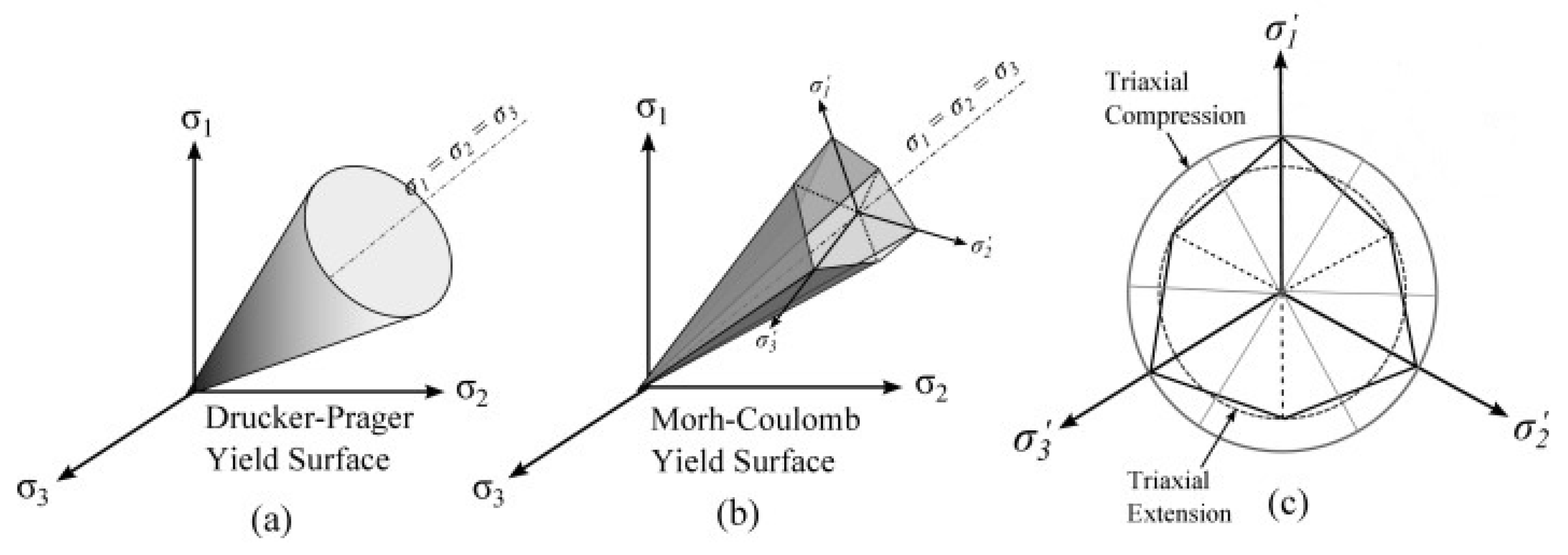
The Drucker–Prager yield criterion (Figure 4) is an isotropic smooth approximation of the Mohr–Columb yield criterion proposed by Drucker and Prager used for geomaterials [36]. Mathematically,
σ = α I 1 +   J 2 k = 0
where I1 = first invariant of stress tensor = σ 1 + σ 2 + σ 3 ; J2 = second invariant of stress tensor = 1 6 σ 1 σ 2 2 + σ 2 σ 3 2 + σ 3 σ 1 2 ; σ 1 , σ 2 , and σ 3 are the principal effective stresses; α and k are material constants dependent upon the internal friction angle, ϕ and cohesion, c defined as
α = 2 s i n ϕ 3 ( 3 s i n ϕ )
k = 6 c c o s ϕ 3 ( 3 s i n ϕ )
This elasto-plastic failure criterion becomes a modification of the von Mises failure criterion when α = 0 [37]. The Drucker–Prager yield criterion tends to overestimate the strength of intact rock, which makes it suitable for defining the strength augmentation of the soft sandstone in the event of impact loading. For this reason, the present study opted for the utilization of this criterion to define the rock mass properties [6,36,37].

2.2.2. Material Properties

The material properties were created for soft sandstone and steel lining in the material library. For soft sandstone, the material properties given in Table 1 were used. The properties used for steel are given in Table 2. The stress–strain parameters and dynamic increase factor (DIF) values for soft sandstone were adopted from Chakraborty [38]. The projectile was assumed to be a rigid non-deformable steel projectile with a weight of 33.665 kg. The material properties from the library were assigned to different parts after creating sections in the property module.

2.3. Boundary Conditions and Loading

After defining the material properties, all the parts created were assembled to fix their position in the global coordinate system in the assembly module. Subsequently, an initial step and an explicit step with a 0.01 time period (10 ms) were created in the step module, and boundary conditions were applied to all the parts. Explicit dynamic analysis is a superior and efficient computation technique for evaluating the dynamic responses of simulations of considerable-sized models within a short time span. This procedure performs a large number of small time increments efficiently using an explicit central-difference time integration rule [40]. The top horizontal boundary was free to displace in all directions, while the bottom horizontal boundary was restrained against both vertical and horizontal displacements. All the side boundaries were allowed for vertical displacements but restrained against horizontal displacements. Gravity loading was applied to the rock and tunnel, and the projectile was given a velocity of 1000 m/s in the predefined fields of the load module. General contact was defined between the projectile and target in the interaction section. Hard contact was employed in the interaction module to define the interaction between the rock/steel interface during the assembly of the different parts in the model. This allowed the transfer of stress between the two surfaces in contact using a kinematic contact algorithm that conserved the momentum between two contacting bodies. Separation was allowed after contact. The assembly at 1 m depth with boundary conditions and loading is shown in Figure 5a.

2.4. Mesh

Adaptive meshing (ALE) was used to define the mesh region of the parts in the step module. This meshing technique is a combination of the features of pure Lagrangian analysis and pure Eulerian analysis that aids in maintaining a superior grade mesh during the entire analysis by allowing the mesh to alter irrespective of the material, even in the case of excessive strain/deformation or material depletion. Arbitrary mesh sizes were assigned to the different parts in the mesh module, and a task was created in the optimization module. Thereafter, the model was analyzed in the job module to observe the results. After the mesh convergence study, C3D8R type elements of size 0.05 for rock, R3D3 type elements of size 0.025 for steel lining, and R3D3 type elements of size 0.01 for the projectile were defined in the mesh module for all the analyses. The meshed assembly at 1 m depth is shown in Figure 5b.

3. Results and Discussion

3.1. Damage Modes of Rock and Tunnel Lining

3.1.1. Tunnel Crown Located at 1 m Depth

The deformation, as well as the stress distribution after 10 ms of the impact on the overburden rock and steel tunnel lining with crown at 1 m depth, are shown in Figure 6. A crater region was visible on the rock after impact, indicating perforation of the rock, as shown in Figure 6a. The projectile was observed to be coming out of the lining after perforating the latter at the crown, as clearly seen in Figure 6b. The steel lining was damaged significantly with a hole in the crown. The tunnel lining was distorted downwards along with the projectile indicating that the stress generated in the tunnel lining was due to the momentum of the projectile.

3.1.2. Tunnel Crown Located at 2 m Depth

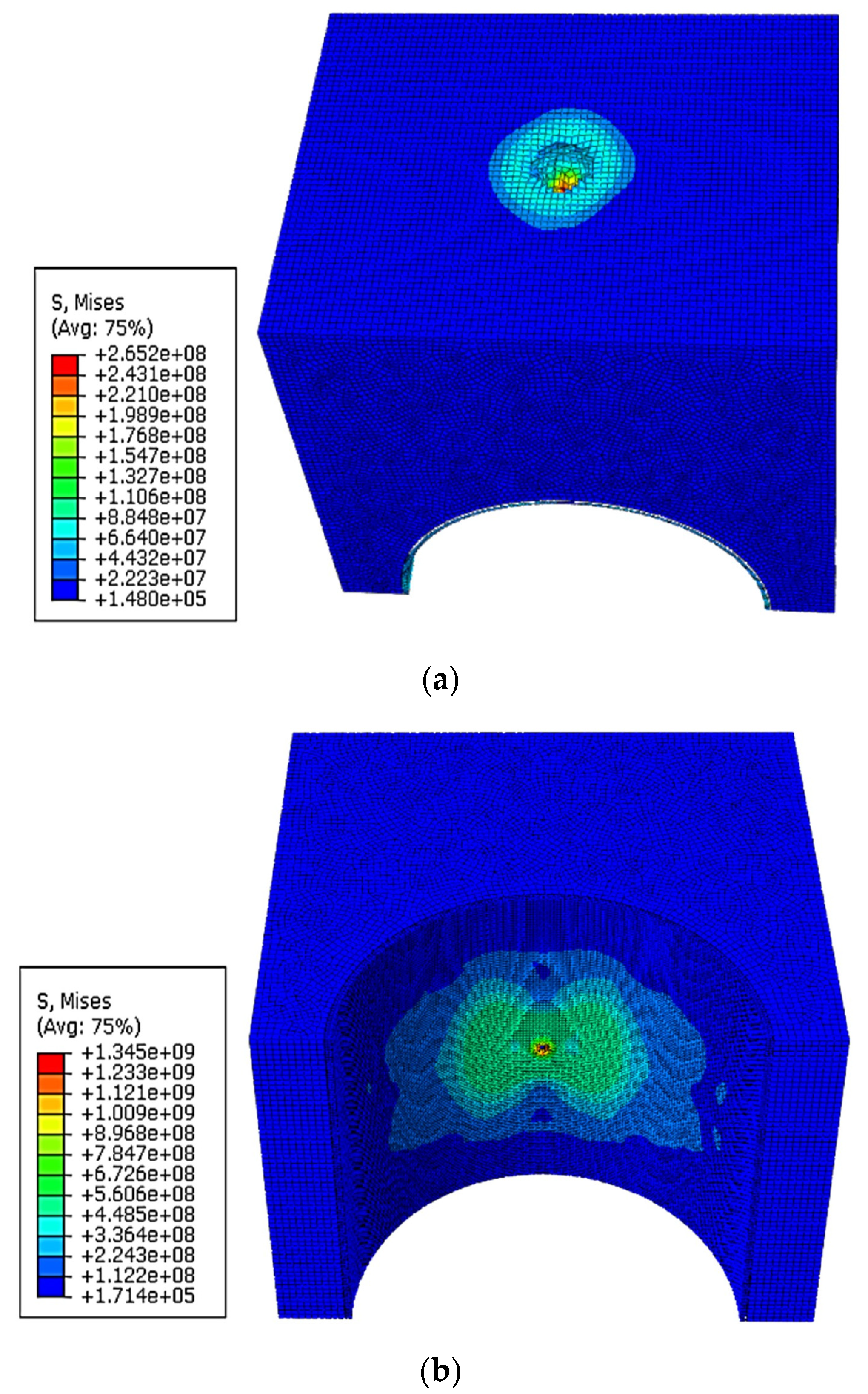
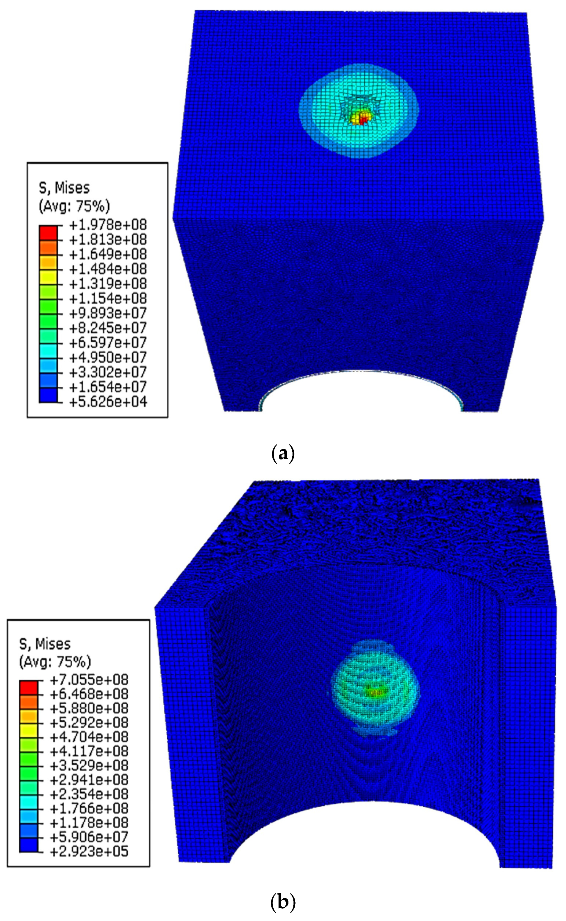
The deformation of the rock and steel tunnel lining with a crown at 2 m depth, along with the respective stress distribution 10 ms after the impact, are illustrated in Figure 7. A crater region with circular stress distribution after 10 ms of the strike was displayed on the rock part after impact, as shown in Figure 7a. The projectile could not perforate the steel lining but damaged it extensively, as seen in Figure 7b. Due to the propagation of shock waves, the tunnel lining was subjected to a high stress, distributed over a combination of two elliptical areas.

3.1.3. Tunnel Crown Located at 3 m Depth

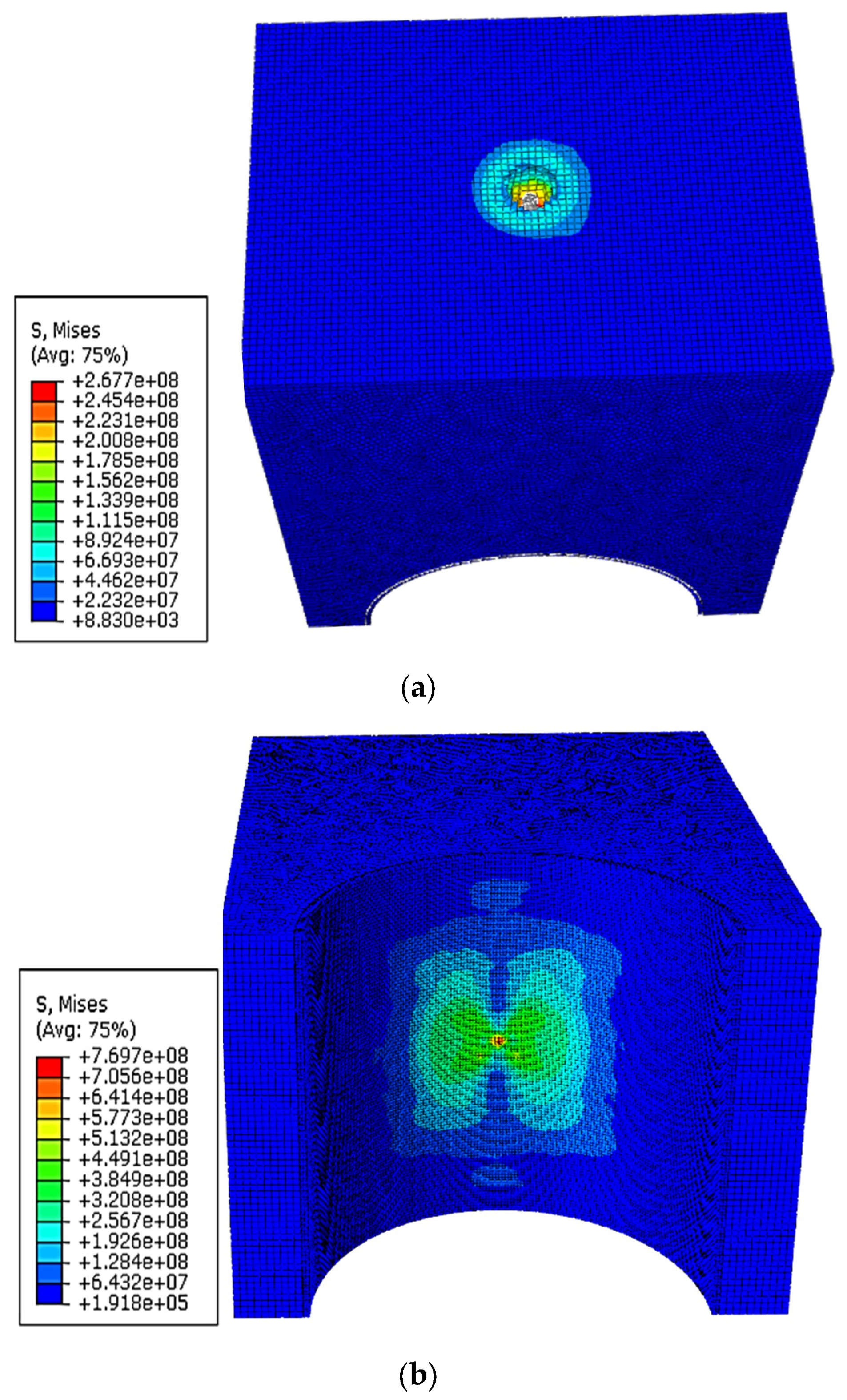
Figure 8 displays the deformation with a stress distribution 10 ms after striking the rock and steel tunnel with 3 m crown depth. The impact created a crater with circular stress distribution on the rock part as shown in Figure 8a. The projectile was not able to perforate the lining at the crown after striking. Only a marginal deformation without any significant damage was observed at the crown from Figure 8b due to the propagation of shock waves. The stress distribution pattern on the tunnel lining was observed to be a combination of two elliptical areas.

3.1.4. Tunnel Crown Located at 4 m Depth

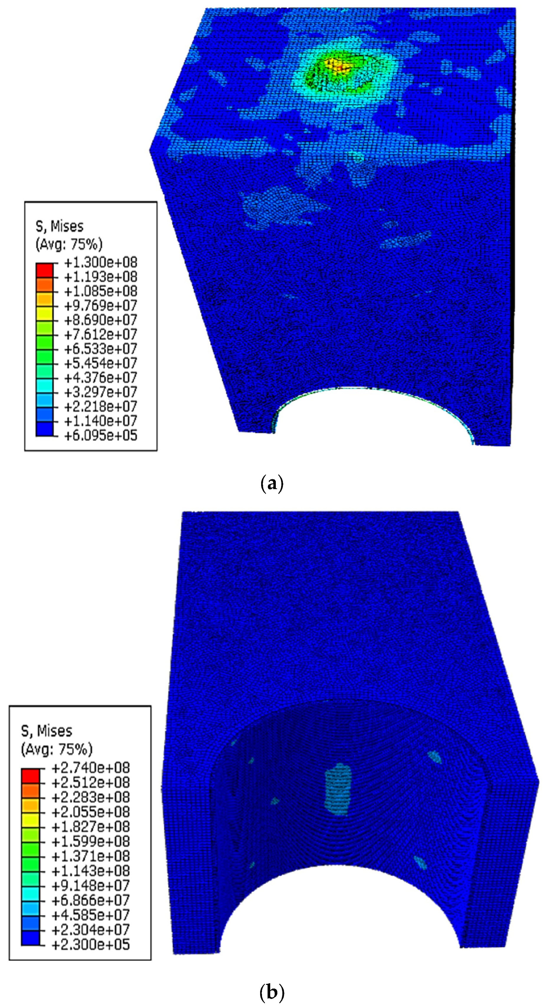
Figure 9 displays the deformation as well as the stress distribution of the rock and steel tunnel lining at 4 m crown depth. A crater with a circular stress distribution pattern was created on the overburden rock by the impact of the projectile, as visible in Figure 9a. The steel lining was not damaged as the projectile could not penetrate the crown, as seen in Figure 9b, although it was subjected to a circular stress distribution due to the formation and propagation of shock waves.

3.1.5. Tunnel Crown Located at 4.5 m Depth

The deformation, along with the stress distribution on the rock and steel tunnel with the crown at 4.5 m depth 10 ms after the impact, are shown in Figure 10. The impact resulted in a crater region with circular stress distribution on the overburden rock, as depicted in Figure 10a. As the projectile could not penetrate the lining, no permanent deformation was observed from Figure 10b at the crown with minor stress distributed over the whole lining due to shock wave propagation.

3.1.6. Tunnel Crown Located at 5 m Depth

The deformation of the rock and steel lining at 5 m crown depth, along with the respective stress distribution, is displayed in Figure 11. A crater region with circular stress distribution similar to the previous cases was visible on the rock part after the impact, as seen from Figure 11a. The projectile could not penetrate the lining. No permanent deformation was observed from Figure 11b at the crown, and a scanty of stress distribution regions due to shock wave propagation were observed scattered over the tunnel lining.

3.2. Stresses on the Tunnel Lining

The variations of von Mises stress/impact load on the tunnel crown with time (stress–time history curve) for different crown depths are represented in Figure 12. The impact load or von Mises stress generated on the tunnel lining 5 ms after the impact at the rock surface for all the tunnel depths due to the propagation of shock waves. The linings at 1 m, 2 m, and 3 m crown depths were subjected to a high stress/impact load, and the stress-time history plot showed typical impact load behavior with propagation of the projectile through the tunnel lining. The stress–time history plots at 1 m and 2 m crown depths displayed two von Mises stress peaks with maximum values of 800.7 MPa and 525.1 MPa at 5 ms and 4 ms after the impact, respectively. The maximum von Mises stress values at 3 m and 4 m crown depths dropped to 486.8 MPa and 220.7 MPa occurring 5.5 ms and 10 ms after the impact, respectively. The impact load/von Mises stress at 4.5 m and 5 m depths were measured as 67.7 MPa and 45.1 MPa at 9 ms and 9.5 ms after the impact, respectively; however, the projectiles were not able to penetrate the tunnel crown. This indicates the propagation of shock waves after the impact, which were not able to influence the tunnel lining at such depth significantly and were non-destructive to the structure.
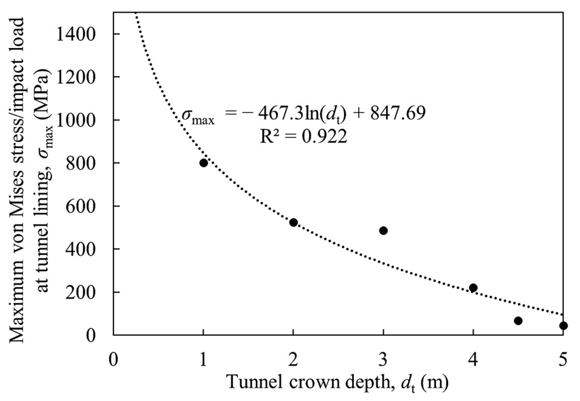
The maximum von Mises stress/impact load generated on the tunnel lining due to the projectile impact is plotted in Figure 13. It was observed that the maximum stress on the tunnel lining started to reduce in a logarithmic trend with an increase in the tunnel crown depth. The regression coefficient (coefficient of determination, R2) for the logarithmic equation of the trend line was calculated as 0.922, which is higher than the acceptable range (>0.7). The impact load became asymptotic with a value less than the yield stress of the tunnel lining material after a tunnel depth of 4.5 m. Therefore, it could be inferred that to minimize the effect of the ballistic load due to a 33.655 kg projectile at a velocity of 1000 m/s, a 3 m diameter tunnel with 50 mm thick steel lining should be located at a crown depth below 4.5 m.

3.3. Displacement of the Projectile Nose

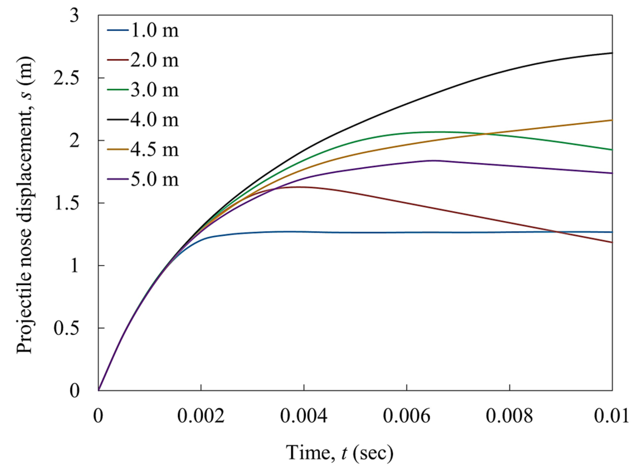
The displacements of the projectile nose for different tunnel depths are plotted in Figure 14. At 1 m tunnel depth, the projectile nose displacement reached a peak of 1.250 m at 2.2 ms, after which the rate of change of displacement became negligible, indicating that the projectile was attached to the lining after perforation. The maximum depth of penetration in this condition was 1.268 m at 10 ms. At 2 m tunnel crown depth, the projectile nose was observed to be displaced to a maximum depth of 1.627 m after 4 ms, which was greater than that of 1 m crown depth. In this case, the rate of change of displacement decreased after the peak, indicating a reversal of projectile direction. At 3 m tunnel depth, the projectile was observed to be displaced to a maximum of 2.066 m after 6.5 ms, showing similar behavior as the crown depth at 2 m. At 4 mand 4.5 m tunnel crown depths, the maximum displacements were 2.698 m, and 2.168 m, respectively. At these crown depths, the projectile nose displacements continued to increase, indicating the advancement of the projectile through the rock mass. At 5 m tunnel depth, the projectile nose was observed to be displaced to a maximum of 1.837 m after 6.5 ms and followed by a reversal of the direction of displacement.
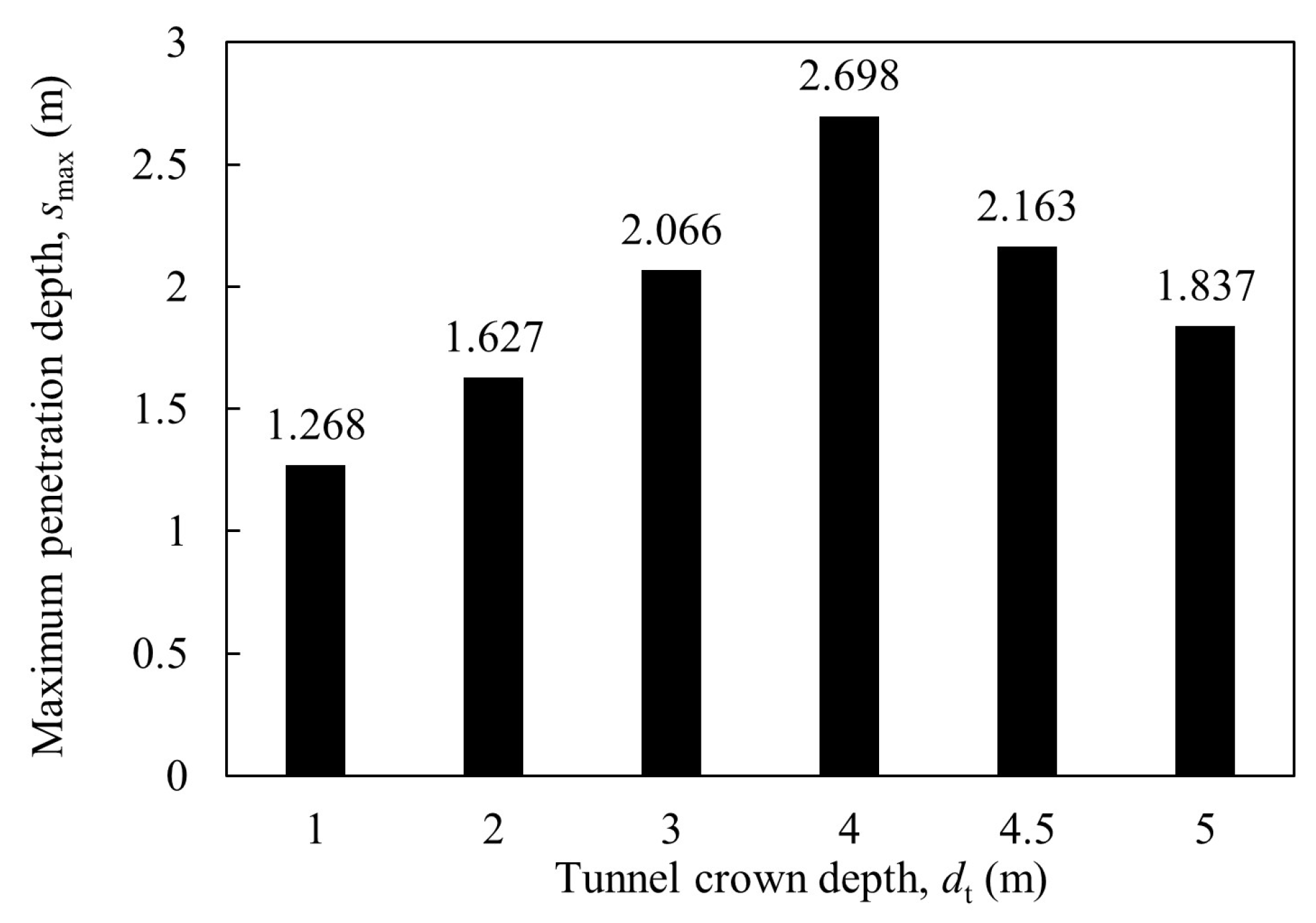
The maximum displacements of the projectile for the tunnel crown at different depths are presented in Figure 15. The maximum depth of penetration showed an increasing trend with increasing crown depth up to 4 m, after which it decreased. At a very shallow crown depth (<4 m), the strength of the steel lining dominated in penetration resistance despite the dynamic strength augmentation in the soft sandstone. The maximum projectile penetration depth was observed as 2.698 m when the tunnel was at a depth of 4 m. The dynamic strength augmentation of soft sandstone was employed to resist the projectile penetration after the depth of 4 m, thus reducing the projectile penetration depth for the crown depth after 4 m.

3.4. Velocity of the Projectile

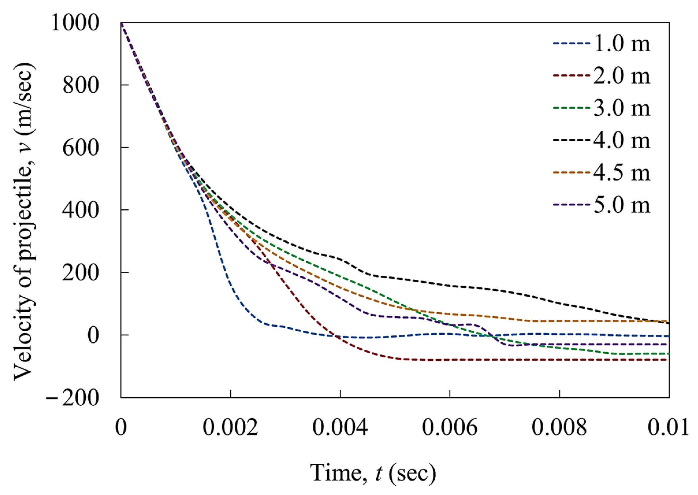
The variations of the velocity of the projectile with time for different tunnel depths are plotted in Figure 16. At 1 m, 4 m, and 5 m tunnel depths, the velocity–time history curves of the projectile were found to be irregular or wavy in nature. At 2 m and 3 m crown depths, the velocity of the projectile became negative at 4 ms and 7 ms indicating a reversal of direction which was also inferred from the projectile nose displacement. The resistance from steel was contributing to this reversal of direction of displacement. At 4 m and 4.5 m crown depths, the velocity of the projectile continued to decrease but did not become negative. As a result, the displacement direction was not reversed. The resistance from rock and its strength augmentation under the dynamic load were contributing to this. At a 5 m crown depth, the rock reduced the velocity of the projectile to a negative value at 6.5 ms, due to which the direction of displacement reversed.

4. Conclusions

In this study, the response of a 3 m diameter shallow tunnel in soft sandstone rock subjected to impact load by a projectile was observed with the help of numerical analysis in ABAQUS/CAE 6.11. The tunnel crowns were placed at different depths from 1 m to 5 m. The Drucker–Prager damage criteria and the Johnson–Cook damage model were used to define the properties of the rock mass and steel tunnel lining, respectively. The non-deformable projectile strikes normal to the rock surface with a velocity of 1000 m/s.
The projectile caused noticeable deformation or damage to the tunnel lining up to a crown depth of 3 m. Moreover, the shape of the stress distribution pattern due to the impact load at the crown appeared unique depending upon the tunnel crown depth from the overburden rock and propagation of shock waves.
At depths of 1 m, 4 m, and 5 m, the velocity–time history curves of the projectile were irregular or wavy in nature. The reversal of the projectile direction was observed at crown depths of 2 m, 3 m, and 5 m. Increasing crown depth had a positive effect on the maximum depth of the projectile penetration up to 4 m tunnel crown depth, after which the effect reversed, making the tunnel safer. The projectile penetrated to a maximum depth of 2.698 m when the tunnel crown was at a depth of 4 m.
The maximum stress at the tunnel lining reduced in a logarithmic trend with an increase in the crown depth, gradually lowering to an impact load less than the yield stress of the tunnel lining material after a crown depth of 4 m. At a very shallow crown depth (< 4 m), the strength of the steel lining dominated the penetration resistance despite the dynamic strength augmentation in the soft sandstone. The influence of dynamic strength augmentation of soft sandstone instigated after a crown depth of 4 m, hindering the projectile penetration into the rock.
From this study, to mitigate the impact of a ballistic load caused by a 33.655 kg projectile traveling at a velocity of 1000 m/sec, it is recommended that a 3 m diameter tunnel, with a 50 mm thick steel lining, should be positioned at or below 4.5 m crown depth.

Author Contributions

R.S.: Conceptualization, visualization, resources, methodology, analysis, validation, writing—original draft preparation, writing—review and editing; T.T.D.: Methodology, resources, writing—review and editing; K.S.R.: Supervision, conceptualization, methodology, validation, writing—review and editing. All authors have read and agreed to the published version of the manuscript.

Funding

This research received no external funding.

Data Availability Statement

The data supporting reported results can be made available upon request.

Conflicts of Interest

The authors declare no conflicts of interest.

References

  1. Jia, J.; Tenorio, V.O.; Zhang, B.; Li, M.; Xin, C. Stability and reliability of a shallow tunnel in soft surrounding rock: Construction technology and prediction. Arab J. Geosci. 2022, 15, 289. [Google Scholar] [CrossRef]
  2. Smith, P.D.; Hetherington, J.G. Blast and Ballistic Loading of Structures; Butterworth-Heinmen Ltd.: Oxford, UK, 1994. [Google Scholar]
  3. Zukas, J.A. High Velocity Impact Dynamics; John Wiley & Sons. Inc.: Hoboken, NJ, USA, 1990. [Google Scholar]
  4. Mishra, S.; Zaid, M.; Rao, K.S.; Gupta, N.K. FEA of Urban Rock Tunnels Under Impact Loading at Targeted Velocity. Geotech. Geol. Eng. 2021, 40, 1693–1711. [Google Scholar] [CrossRef]
  5. Rajasekaran, S. Structural Dynamics of Earthquake Engineering; Series in Civil and Structural Engineering; Woodhead Publishing: Cambridge, UK, 2009. [Google Scholar] [CrossRef]
  6. Zhu, W.C.; Bai, Y.; Li, X.B.; Niu, L.L. Numerical simulation on rock failure under combined static and dynamic loading during SHPB tests. Int. J. Impact Eng. 2012, 49, 142–157. [Google Scholar] [CrossRef]
  7. Aziznejad, S.; Esmaieli, K.; Hadjigeorgiou, J.; Labrie, D. Responses of jointed rock masses subjected to impact loading. J. Rock Mech. Geotech. Eng. 2018, 10, 624–634. [Google Scholar] [CrossRef]
  8. Gupta, N.K.; Madhu, V. An Experimental Study of Normal and Oblique Impact of Hard-Core Projectile on Single and Layered Plates. Int. J. Impact Eng. 1997, 19, 395–414. [Google Scholar] [CrossRef]
  9. Gupta, N.K.; Iqbal, M.A.; Sekhon, G.S. Effect of Projectile Nose Shape, Impact Velocity and Target Thickness on Deformation Behaviour of Aluminum Plates. Int. J. Solids Struct. 2007, 44, 3411–3439. [Google Scholar] [CrossRef]
  10. Hoge, L.R.; Shugar, T.A. Three Dimensional Finite Element Modelling of Confinement Stress for Projectiles Embedded in Rock—A Preliminary Study; Defense Technical Information Center (DTIC): Port Hueneme, CA, USA, 1992; 93043–94328. [Google Scholar]
  11. Børvik, T.; Dey, S.; Clausen, A.H. Perforation Resistance of Five Different High Strength Steel Plates Subjected to Small-arms Projectiles. Int. J. Impact Eng. 2009, 36, 948–964. [Google Scholar] [CrossRef]
  12. Forrestal, M.J.; Altman, B.S.; Cargile, J.D.; Hanchak, S.J. An Empirical Equation for Penetration Depth of Ogive- Nose Projectiles into Concrete Targets. Pergamon. Int. J. Impact Eng. 1994, 15, 395–405. [Google Scholar] [CrossRef]
  13. Backman, M.; Goldsmith, W. The Mechanics of Penetration of Projectiles into Targets. Int. J. Eng. Sci. 1978, 16, 1–99. [Google Scholar] [CrossRef]
  14. Forrestal, M.J.; Piekutowski, A.J. Penetration Experiments with 6061-T6511 Aluminum Targets and Spherical-Nose Steel Projectiles at Striking Velocities between 0.5 And 3.0 km/s. Int. J. Impact Eng. 2000, 24, 57–67. [Google Scholar] [CrossRef]
  15. Lixin, Q.; Yunbin, Y.; Tong, L. A Semi-Analytical Model for Truncated-Ogive-Nose Projectiles Penetration into Semi-infinite Concrete Targets. Int. J. Impact Eng. 2000, 24, 947–955. [Google Scholar] [CrossRef]
  16. Senthil, K.; Iqbal, M.A.; Gupta, N.K. Thin Metallic Plates Subjected to Projectile Impact. In Proceedings of the International Conference of Impact Loading of Lightweight Structures, Cape Town, South Africa, 12–16 January 2014. [Google Scholar]
  17. Zha, T.; Li, J.; Lv, S.; Chen, Z. Residual velocity for truncated ogival-nose projectile into stiffened plates. Ships Offshore Struct. 2016, 11, 636–644. [Google Scholar]
  18. Senthil, K.; Iqbal, M.A.; Arindam, B.; Mittal, R.; Gupta, N.K. Ballistic resistance of 2024 aluminium plates against hemispherical, sphere and blunt nose projectiles. Thin-Waled Struct. 2018, 126, 94–105. [Google Scholar] [CrossRef]
  19. Ambriško, L.; Marasová, D. Experimental Research of Rubber Composites Subjected to Impact Loading. Appl. Sci. 2020, 10, 8384. [Google Scholar] [CrossRef]
  20. Erdem, R.T. Dynamic responses of reinforced concrete slabs under sudden impact loading. Rev. Constr. 2021, 20, 346–358. [Google Scholar]
  21. Teixeira, P.; Pina, L.; Rocha, R.; Sadek, S. Parametric analysis of energy absorption capacity of thin aluminum plates impacted by rigid spherical projectiles. Thin-Waled Struct. 2021, 159, 107240. [Google Scholar] [CrossRef]
  22. Alsabhan, A.H.; Sadique, M.R.; Alqarni, A.S.; Alam, S.; Suh, W. Behavior of Sedimentary Rock Tunnel against Rigid Projectile Impact. Appl. Sci. 2022, 12, 9595. [Google Scholar] [CrossRef]
  23. Anas, S.M.; Alam, M.; Shariq, M. Behavior of two-way RC slab with different reinforcement orientation layouts of tension steel under drop load impact. Mater. Today Proc. 2023, 87, 30–42. [Google Scholar] [CrossRef]
  24. Gahoi, A.; Zaid, M.; Mishra, S.; Rao, K.S. Numerical Analysis of the Tunnels Subjected to Impact Loading. In Proceedings of the 7th Indian Rock conference (Indorock2017), New Delhi, India, 25–27 October 2017. [Google Scholar]
  25. Zhou, L.; Zhu, Z.; Wang, M. Dynamic propagation behaviour of cracks emanating from tunnel edges under impact loads. Soil Dyn. Earthq Eng. 2018, 105, 119–126. [Google Scholar] [CrossRef]
  26. Baziar, M.H.; Shahnazari, H.; Kazemi, M. Mitigation of surface impact loading effects on the underground structures with geofoam barrier: Centrifuge modeling. Tunn. Undergr. Sp. Technol. 2018, 80, 128–142. [Google Scholar] [CrossRef]
  27. Mishra, S.; Rao, K.S.; Gupta, N.K.; Kumar, A. Damage to shallow tunnels in different geomaterials under static and dynamic loading. Thin-Walled Struct. 2018, 126, 138–149. [Google Scholar] [CrossRef]
  28. Zhou, L.; Zhu, Z.; Dong, Y. The influence of impacting orientations on the failure modes of cracked tunnel. Int. J. Impact Eng. 2019, 125, 134–142. [Google Scholar] [CrossRef]
  29. Mishra, S.; Kumar, A.; Rao, K.S.; Gupta, N.K. Experimental and numerical investigation of the dynamic response of tunnel in soft rocks. Structures 2021, 29, 2163–2173. [Google Scholar] [CrossRef]
  30. Zaid, M. Dynamic stability analysis of rock tunnels subjected to impact loading with varying UCS. Geomech. Eng. 2021, 24, 505–518. [Google Scholar]
  31. Zaid, M. Preliminary Study to Understand the Effect of Impact Loading and Rock Weathering in Tunnel Constructed in Quartzite. Geotech. Geol. Eng. 2021, 42, 725–753. [Google Scholar] [CrossRef]
  32. Thai, D.K.; Tran, M.T.; Phan, Q.M.; Pham, T.H. Local damage of the RC tunnels under ballistic missile impact investigated by finite element simulations. Structures 2021, 31, 316–329. [Google Scholar] [CrossRef]
  33. Senthil, K.; Pelecanos, L.; Rupali, S.; Sharma, R.; Saini, K.; Iqbal, M.A.; Gupta, N.K. Experimental and numerical investigation of transient dynamic response on reinforced concrete tunnels against repeated impact loads. Int. J. Impact Eng. 2023, 178, 104604. [Google Scholar] [CrossRef]
  34. Forrestal, M.J.; Luk, V.K. Penetration into Soil Targets. Int. J. Impact Eng. 1992, 12, 427–444. [Google Scholar] [CrossRef]
  35. Johnson, G.R.; Cook, W.H. Fracture Characteristics of Three Metals Subjected to Various Strains, Strain Rates, Temperatures and Pressures. Eng. Fract. Mech. 1985, 21, 3148. [Google Scholar] [CrossRef]
  36. Garner, S.; Strong, J.; Zavaliangos, A. The extrapolation of the Drucker–Prager/Cap material parameters to low and high relative densities. Powder Technol. 2015, 28, 210–226. [Google Scholar] [CrossRef]
  37. Alejano, L.R.; Bobet, A. Drucker–Prager Criterion. Rock Mech. Rock Eng. 2012, 45, 995–999. [Google Scholar] [CrossRef]
  38. Chakraborty, T. Impact Simulation of Rocks under SHPB Test. Proc. Indian Natl. Sci. Acad. 2013, 79, 605. [Google Scholar] [CrossRef]
  39. Børvik, T.; Hopperstad, O.S.; Berstad, T.; Langseth, M. Perforation of 12mm Thick Steel Plates by 20mm Diameter Projectiles with Flat, Hemispherical and Conical Noses Part II: Numerical Simulations. Pergamon. Int. J. Impact Eng. 2002, 27, 37–64. [Google Scholar] [CrossRef]
  40. Abaqus v6.11 User’s Manual; Abaqus Inc., DS Simulia: Providence, RI, USA, 2011.
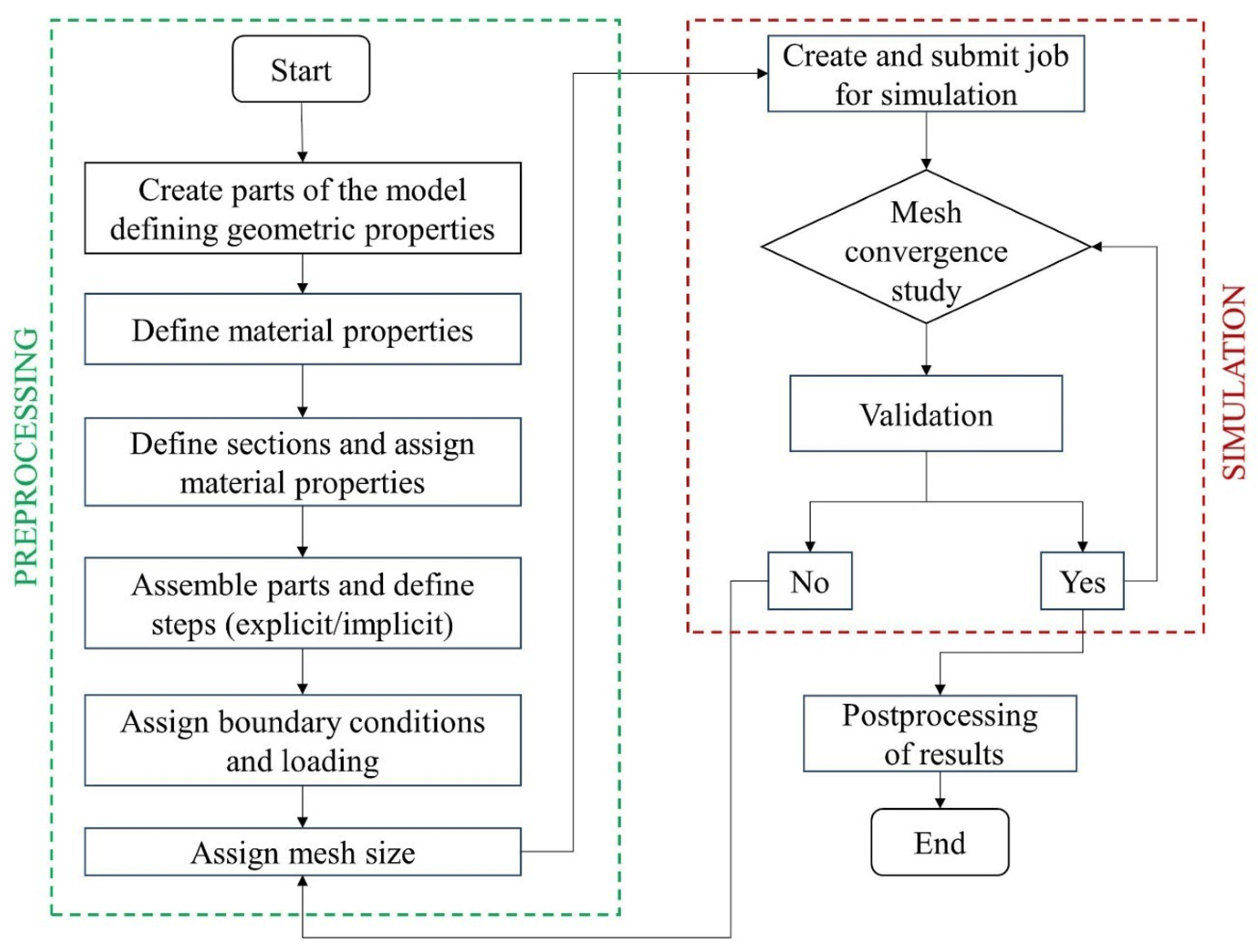
Figure 1. Flow chart of the numerical analysis procedure using ABAQUS/CAE.
Infrastructures 09 00049 g001
Figure 2. Projectile geometry (a) Dimension of the projectile; reproduced with permission from [34] published by Elsevier, 1992, and (b) Perspective view of the projectile created in ABAQUS/CAE.
Infrastructures 09 00049 g002
Figure 3. Schematic of the tunnel at 1 m crown depth with the surrounding rock mass (a) front view, and (b) side view.
Infrastructures 09 00049 g003
Figure 4. The yield surfaces of (a) Drucker–Prager, (b) Mohr–Coulomb, and (c) in π plane. Reproduced with permission from [36] published by Elsevier, 2015.
Infrastructures 09 00049 g004
Figure 5. (a) Assembly with tunnel crown at 1 m depth showing boundary conditions and loading, and (b) Meshed assembly with tunnel crown at 1 m depth.
Infrastructures 09 00049 g005
Figure 6. Deformation at the striking point of the (a) rock surface, and (b) steel lining with tunnel crown at 1 m depth.
Infrastructures 09 00049 g006
Figure 7. Deformation at the striking point of the (a) rock surface, and (b) steel lining with tunnel crown at 2 m depth.
Infrastructures 09 00049 g007
Figure 8. Deformation at the striking point of the (a) rock surface, and (b) steel lining with tunnel crown at 3 m depth.
Infrastructures 09 00049 g008
Figure 9. Deformation at the striking point of the (a) rock surface, and (b) steel lining with tunnel crown at 4 m depth.
Infrastructures 09 00049 g009
Figure 10. Deformation at the striking point of the (a) rock surface, and (b) steel lining with tunnel crown at 4.5 m depth.
Infrastructures 09 00049 g010
Figure 11. Deformation at the striking point of the (a) rock surface, and (b) steel lining with tunnel crown at 5 m depth.
Infrastructures 09 00049 g011
Figure 12. Variation of von Mises stress/impact load with time on the tunnel lining with crowns depths at (a) 1 m, (b) 2 m, (c) 3 m, (d) 4 m, (e) 4.5 m, and (f) 5 m.
Infrastructures 09 00049 g012
Figure 13. Relationship between maximum von Mises stress/impact load on the tunnel lining and tunnel crown depths.
Infrastructures 09 00049 g013
Figure 14. Relationship between displacement of projectile nose and time for tunnels at different crown depths.
Infrastructures 09 00049 g014
Figure 15. Maximum penetration depth of projectile for different tunnel crown depths.
Infrastructures 09 00049 g015
Figure 16. Relationship between velocity of the projectile nose and time for tunnels at different crown depths.
Infrastructures 09 00049 g016
Table 1. Material parameters for soft sandstone. Reproduced from [10] published by DTIC (USA), 1992.
Density,
ρ
Young’s Modulus,
E
Poisson’s Ratio,
υ
Angle of Friction,
ϕ
Flow Stress RatioDilation Angle,
ψ
2291 kg/m313.6 × 109 N/m20.3530°0.778
Table 2. Material parameters of steel tunnel lining. Reproduced with permission from [39] published by Elsevier, 2002.
ParameterValue
Modulus of elasticity, E200 × 109 N/m2
Poisson’s ratio, υ0.3
Density, ρ7850 kg/m3
Yield stress constant, A490 × 106 N/m2
Strain hardening constantsB807 × 106 N/m2
n0.73
Viscous effect constant, C0.001
Thermal softening constant, m0.94
Reference strain rate, ε01.000 s−1
Melting temperature, θmelt1800 K
Transition temperature, θtransition293 K
Fracture strain constants,D10.0705
D21.732
D30.54
D4−0.015
Disclaimer/Publisher’s Note: The statements, opinions and data contained in all publications are solely those of the individual author(s) and contributor(s) and not of MDPI and/or the editor(s). MDPI and/or the editor(s) disclaim responsibility for any injury to people or property resulting from any ideas, methods, instructions or products referred to in the content.