
Fatigue Consideration for Tension Flange over Intermediate Support in Skewed Continuous Steel I-Girder Bridges

 ,
,  ,
,  and
and
Abstract
1. Introduction
1.1. Background
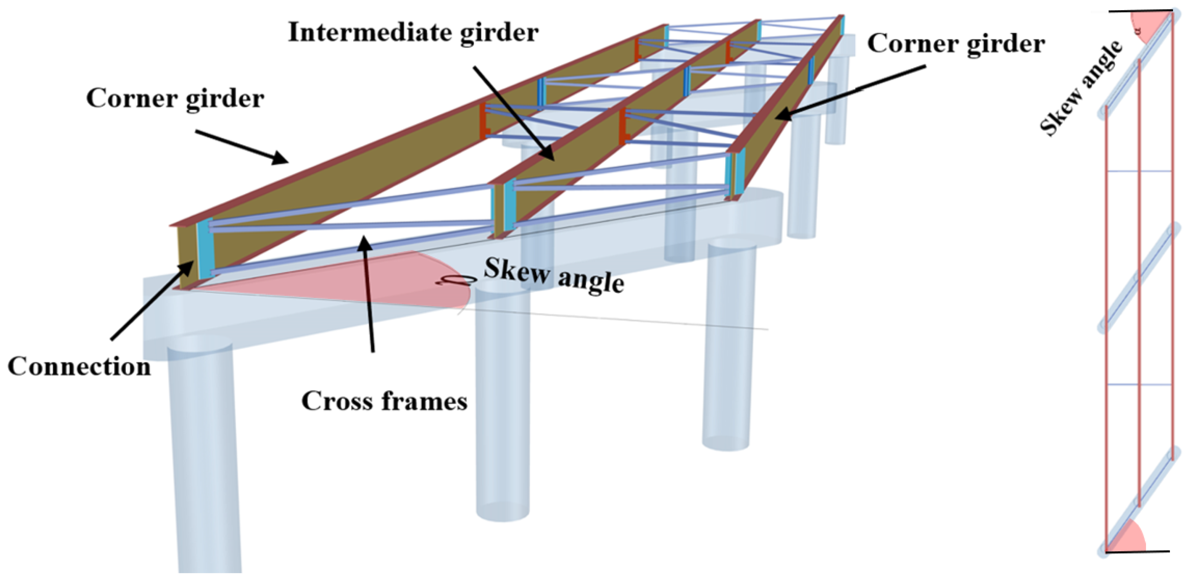
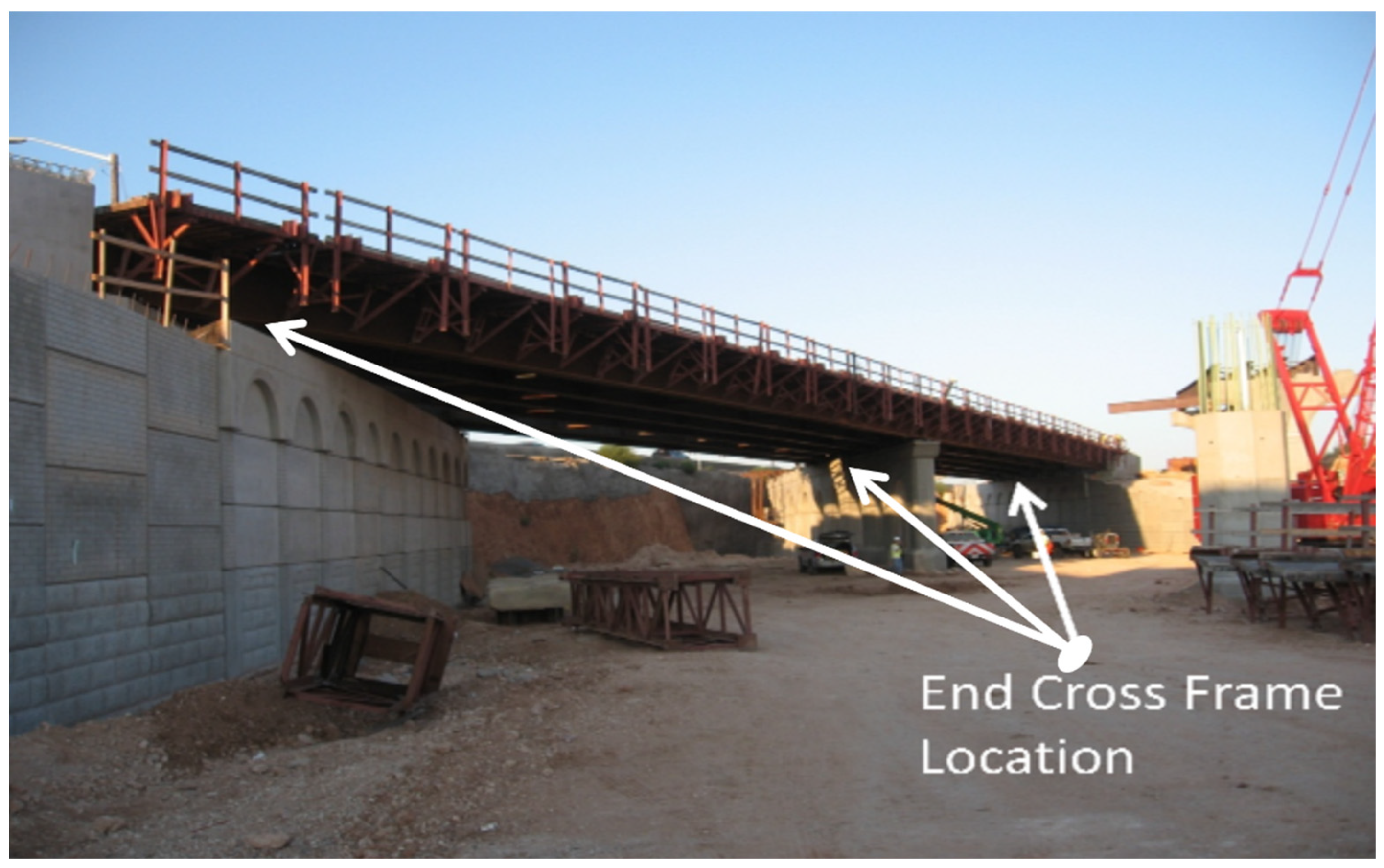
1.1.1. Cross-Frames in Skewed Steel Girder Bridges
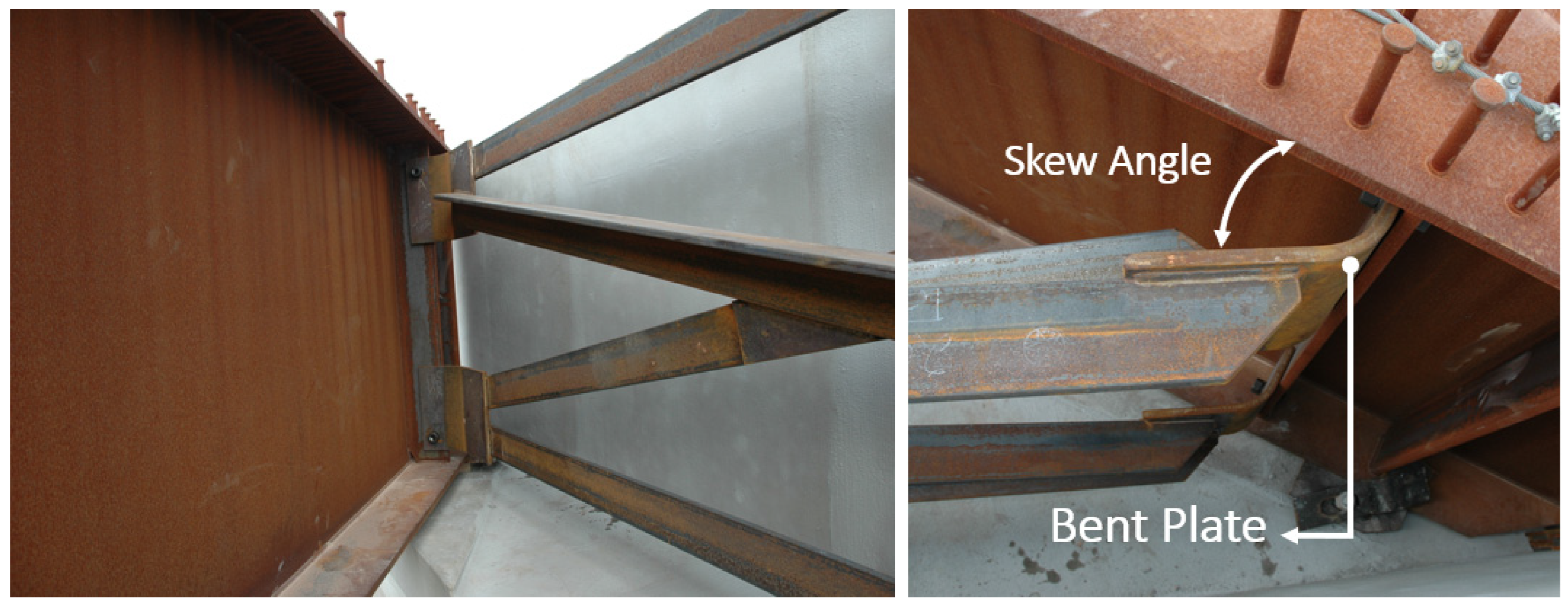
1.1.2. Skewed Connections in Bridges
Bent Plate Connection
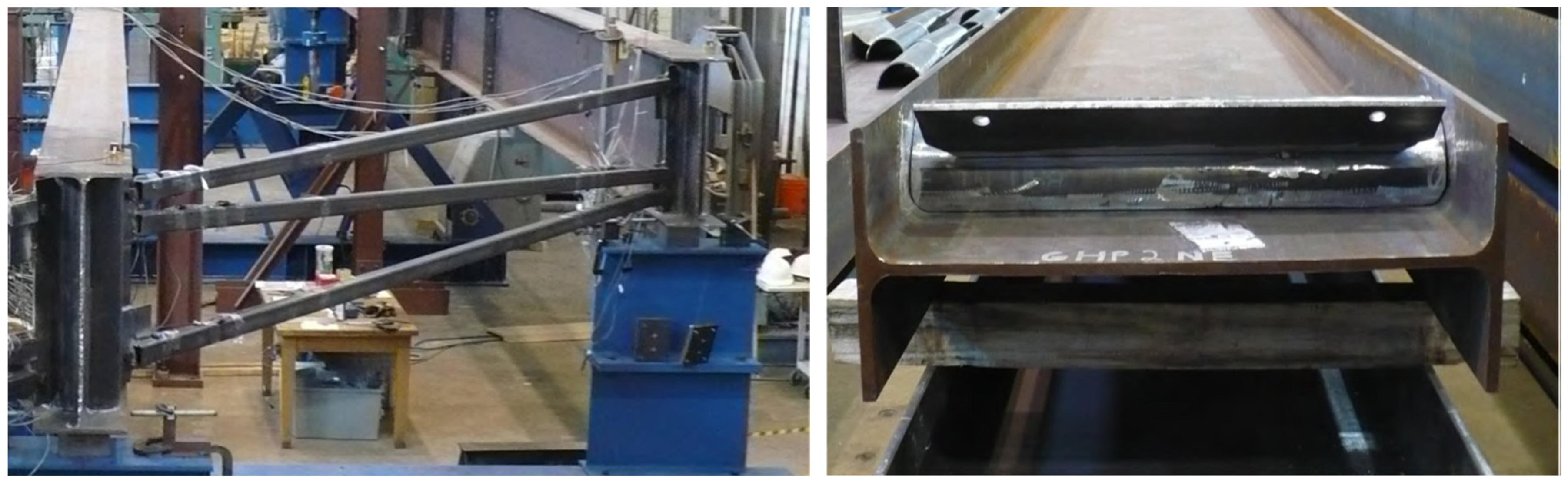
Half-Round Bearing Stiffener Connections (HRBS)
2. Methodology
2.1. Selection of the Representative Bridges for Analytical Study
2.2. FEM Modeling
2.2.1. General Assumptions
Structural Elements
Materials
Dimensions and Quantities
2.2.2. Fatigue Loading
3. Results and Discussions
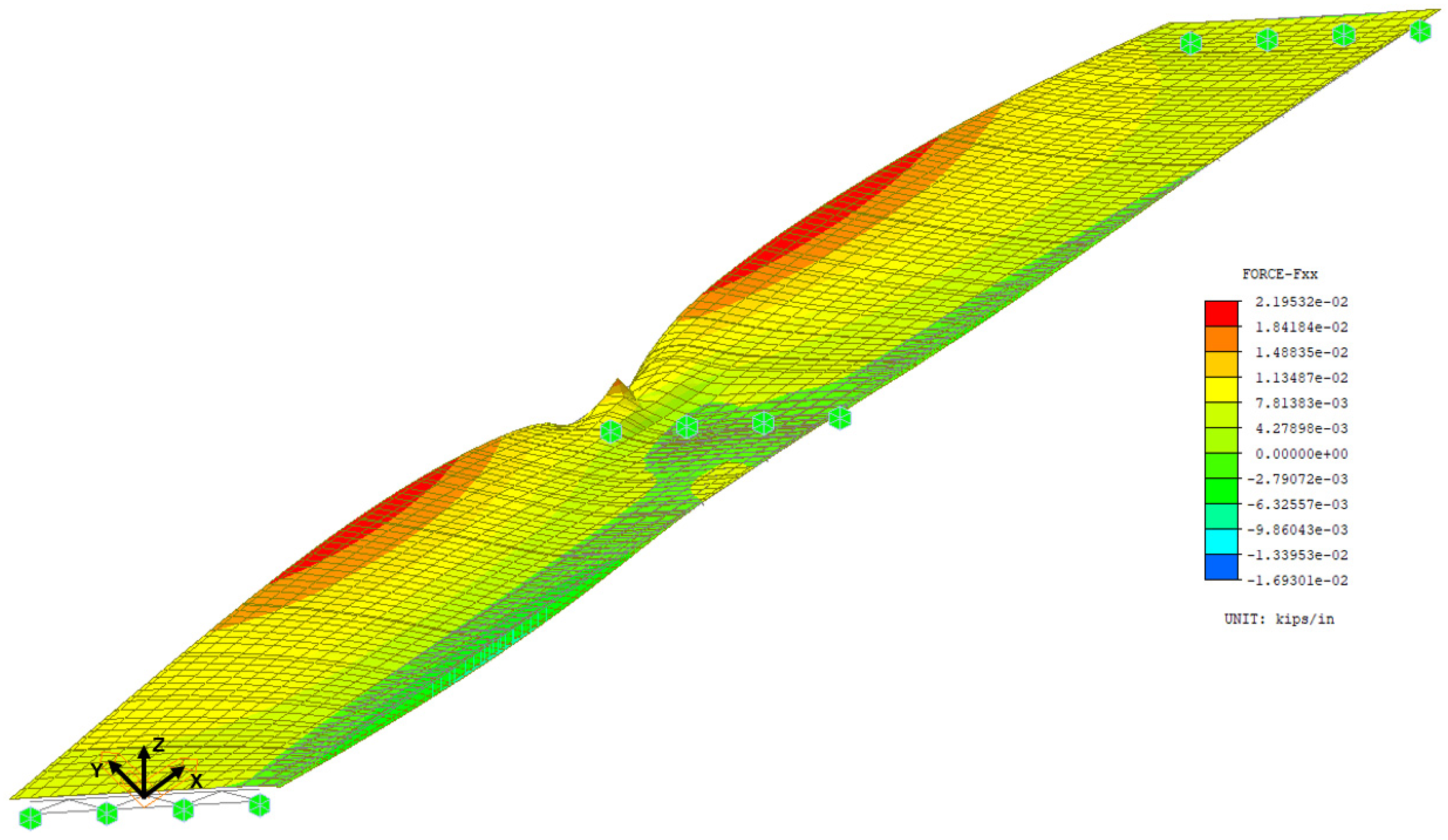
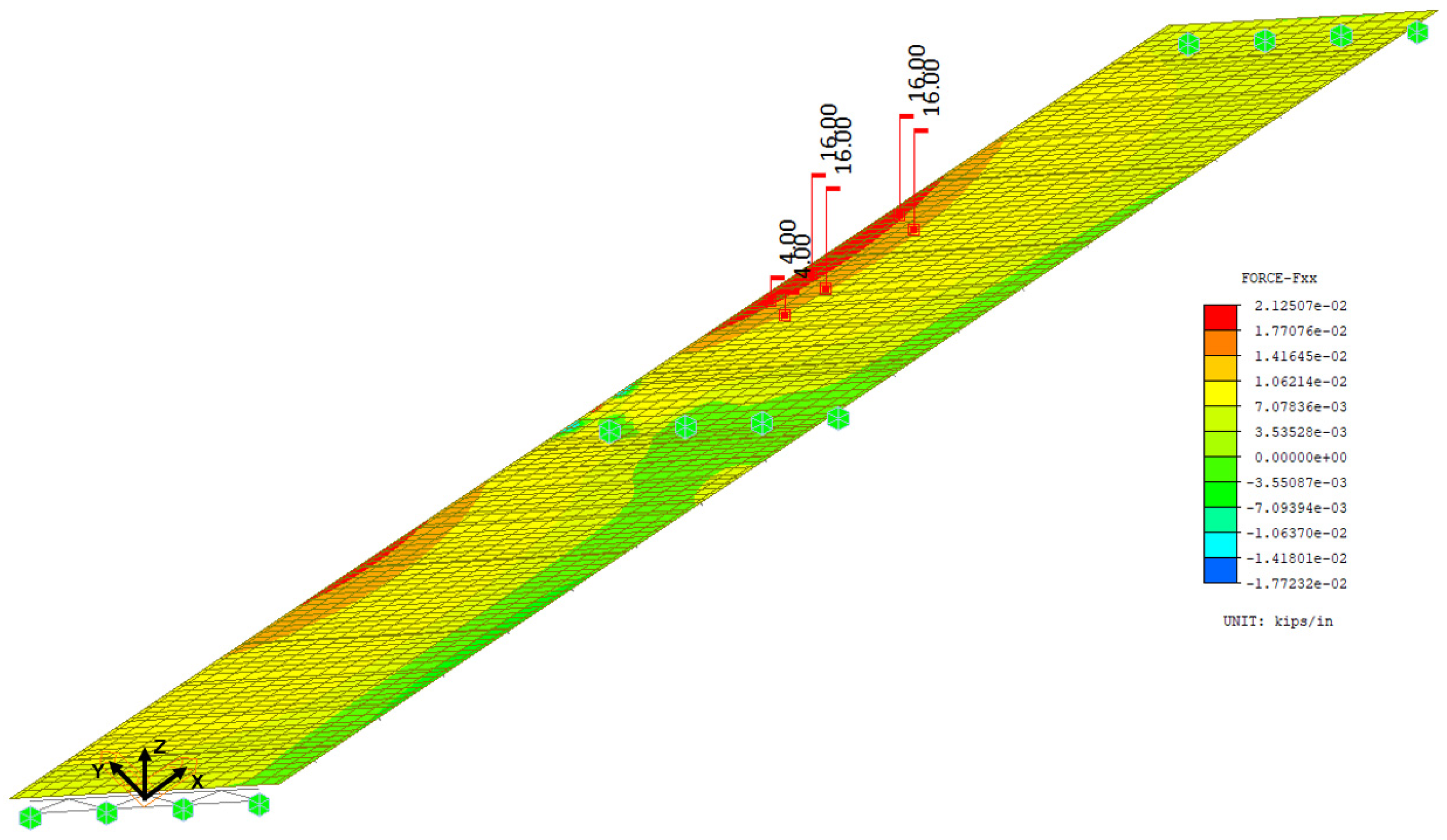
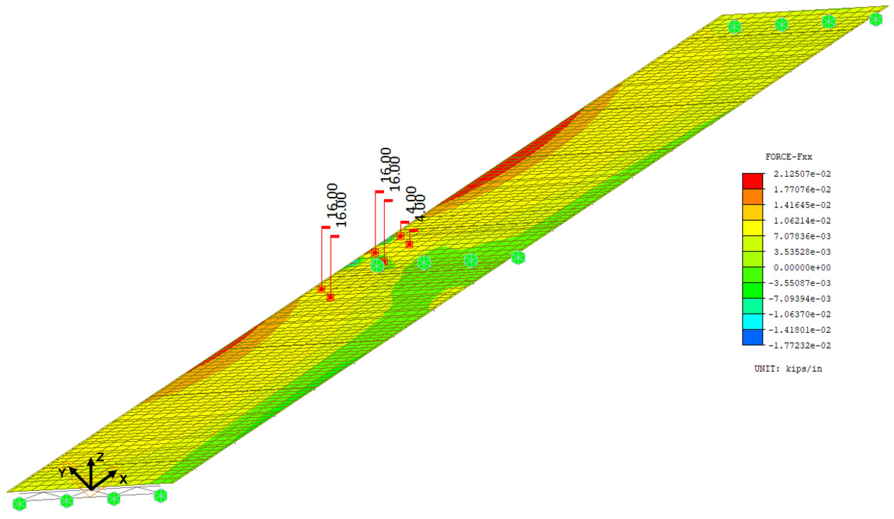
3.1. Fatigue Stress Ranges in Top Flanges over Skewed Piers
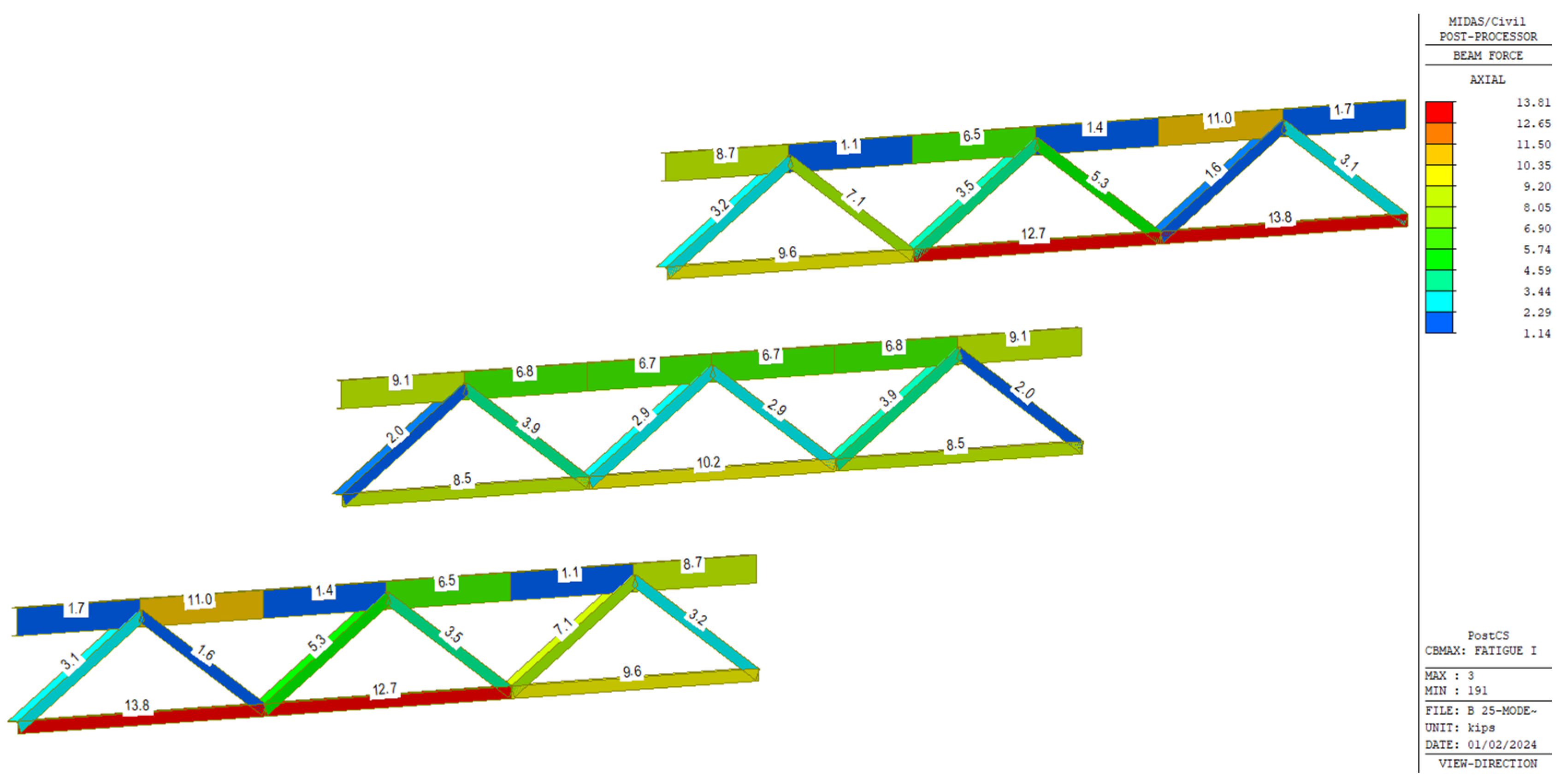
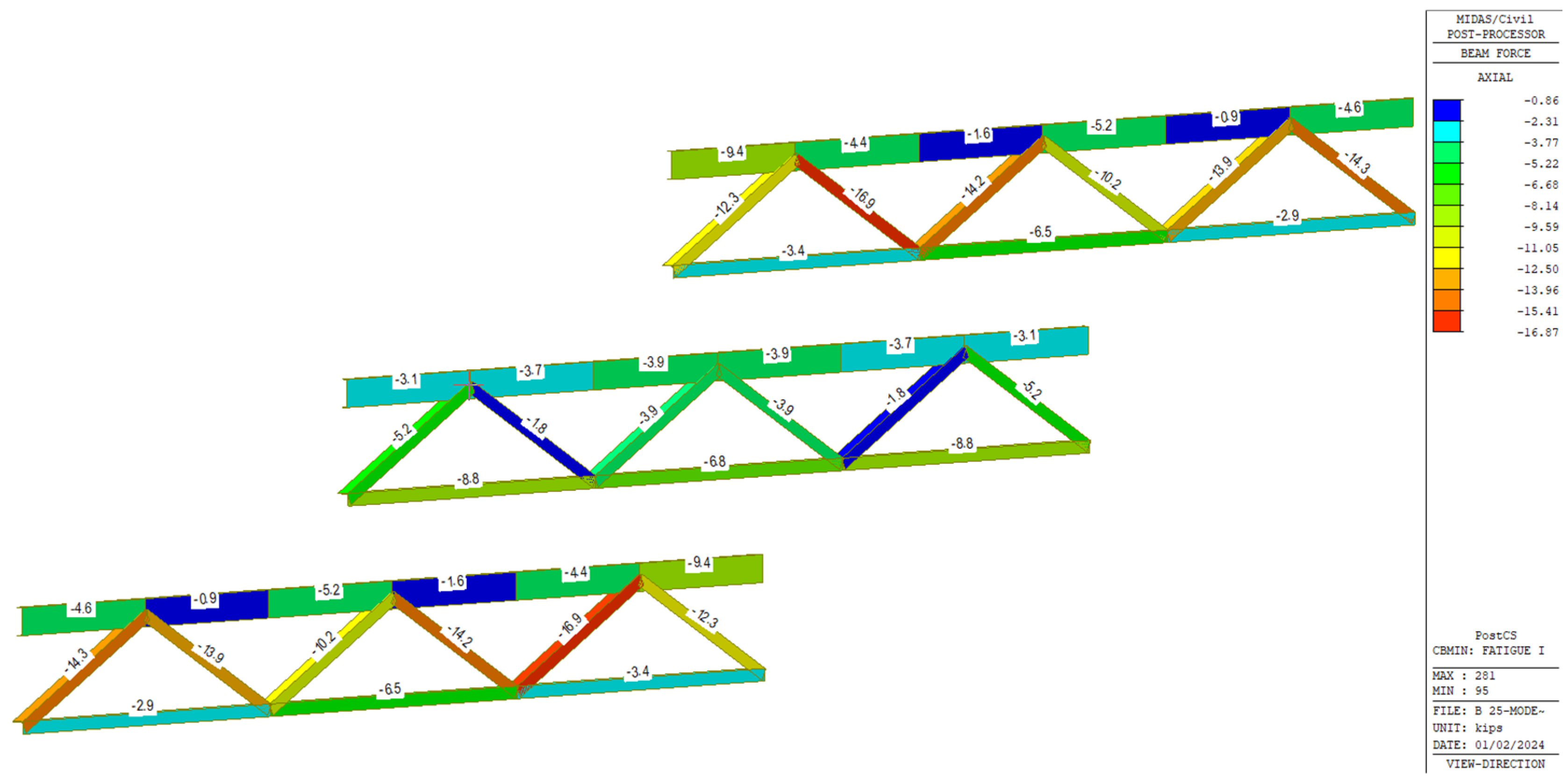
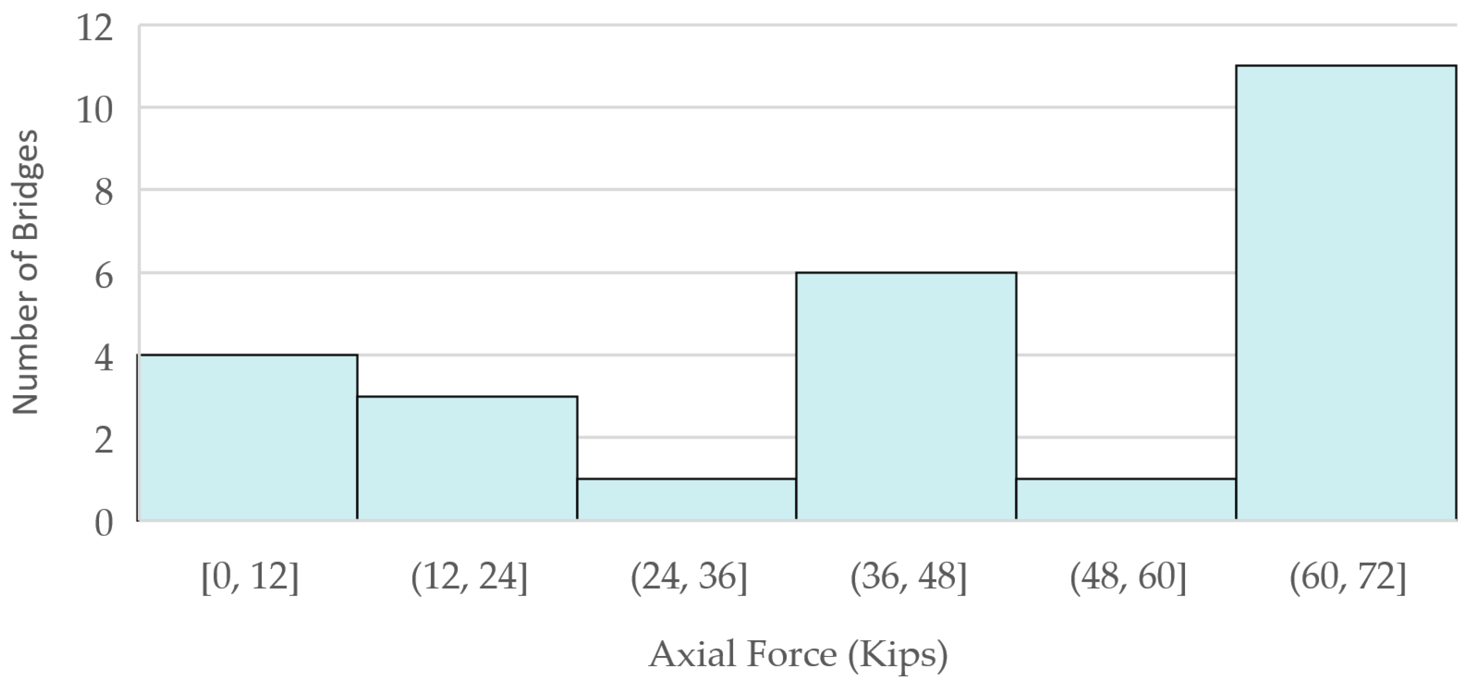
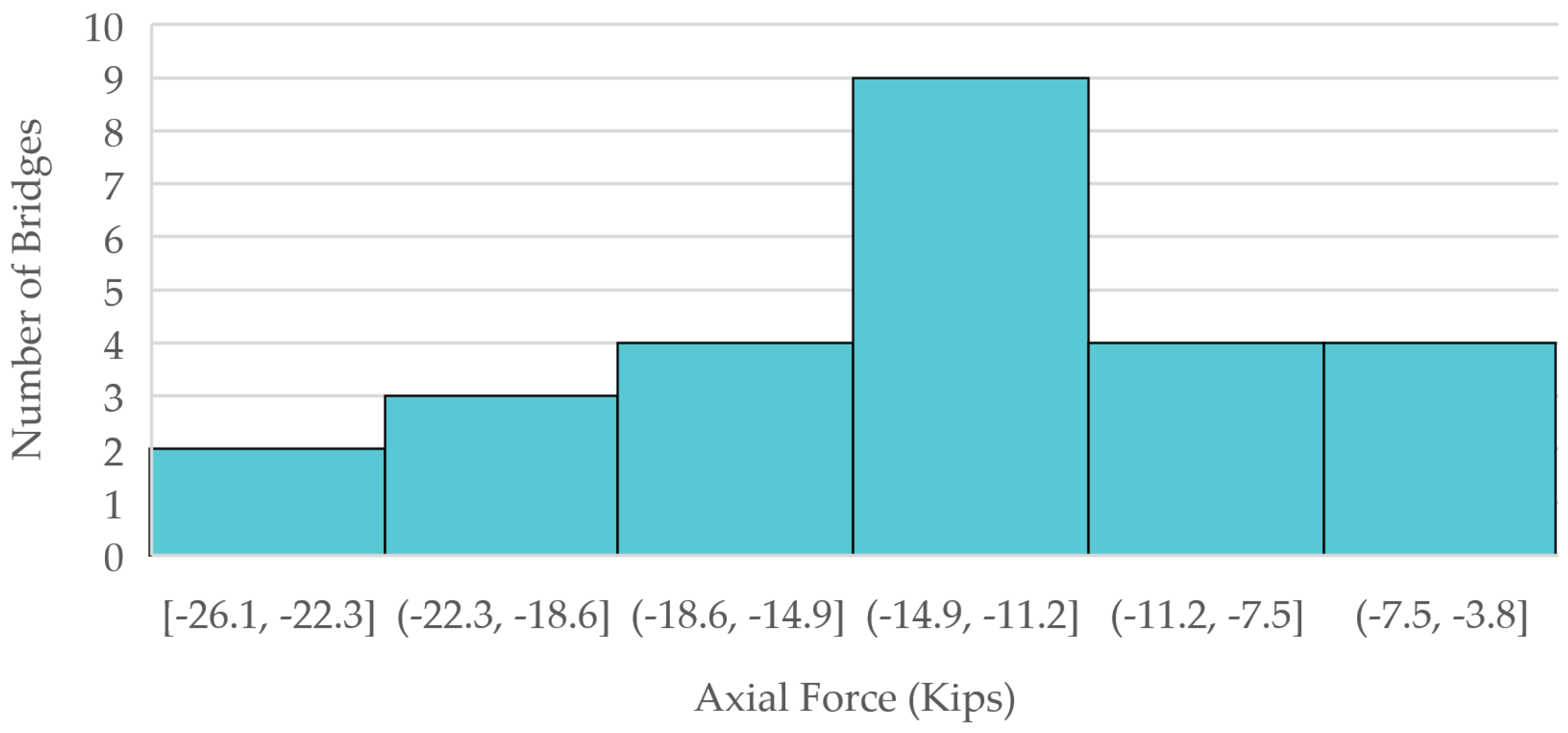
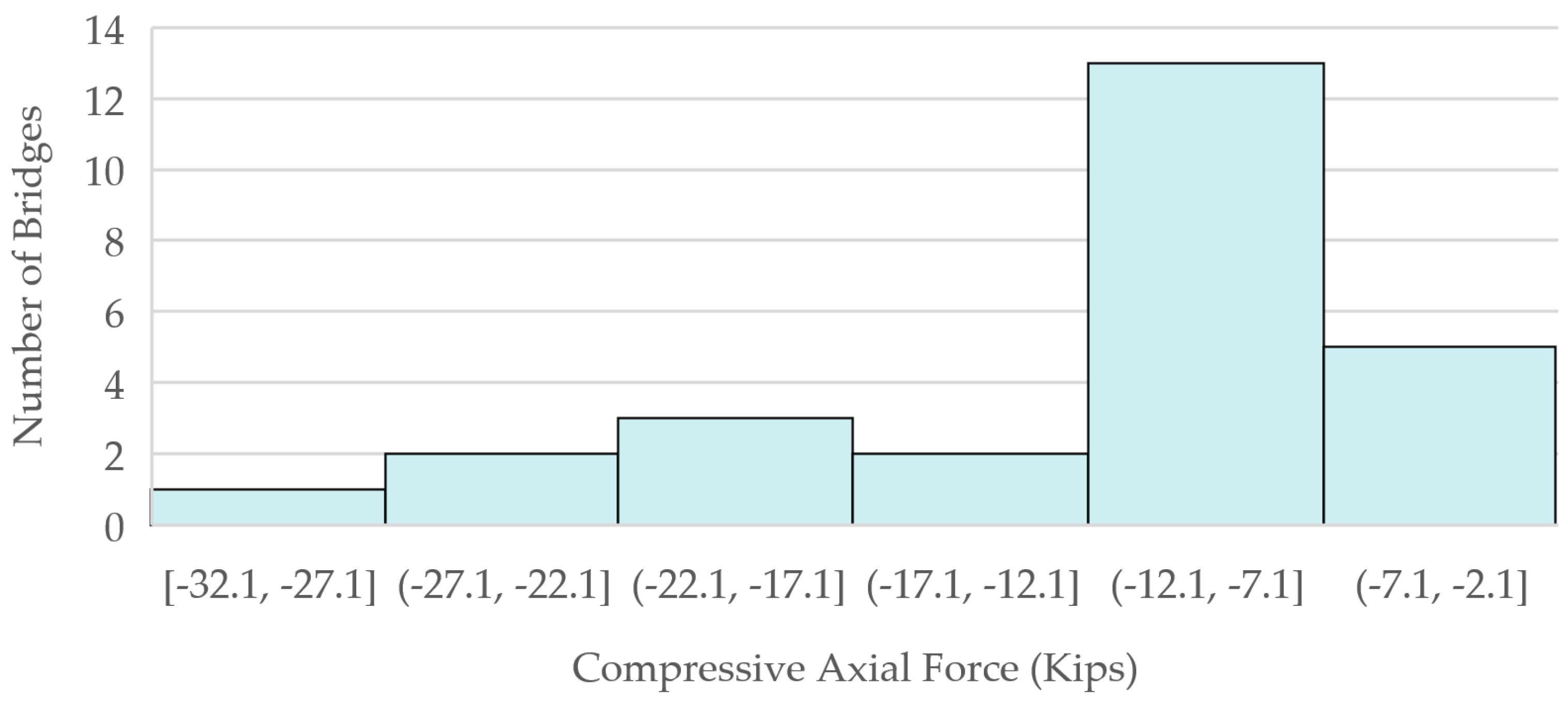
3.2. Cross-Frame Forces for Fatigue Envelope
3.3. Fatigue Consideration in Skewed Connections
4. Conclusions
- Finite element analyses of 26 bridges representing the range of geometries of skew bridges in the State of Florida were utilized to quantify flange fatigue stress ranges and axial forces in the cross-frame members for fatigue assessment.
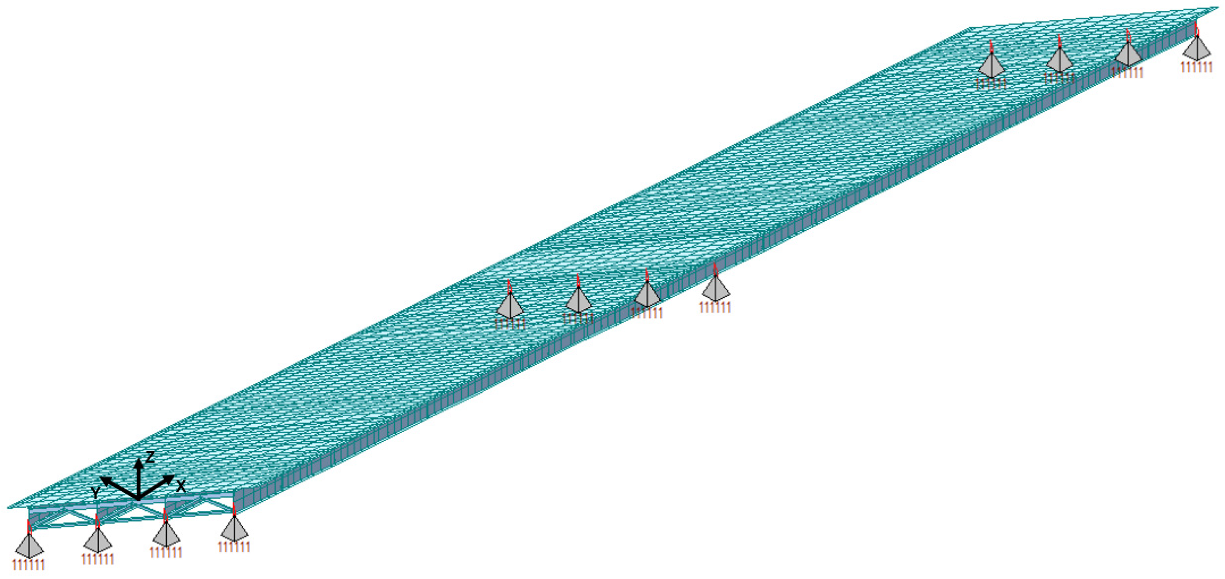
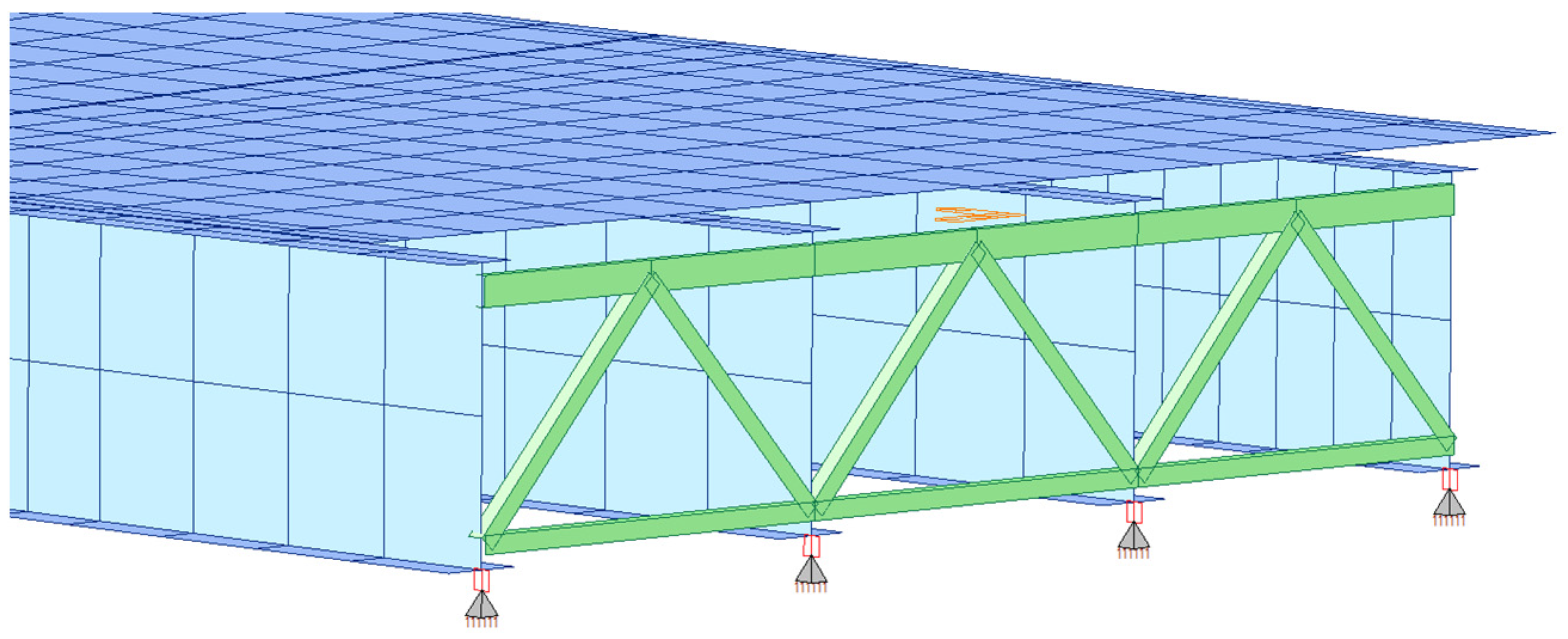
- A preliminary analysis helped to identify the appropriate modeling details. This included the use of plate FE elements for the deck and girders, and beam elements for cross-frame members. Also, the analysis showed that the effect of modeling the substructure is negligible when the neoprene bearings are included.
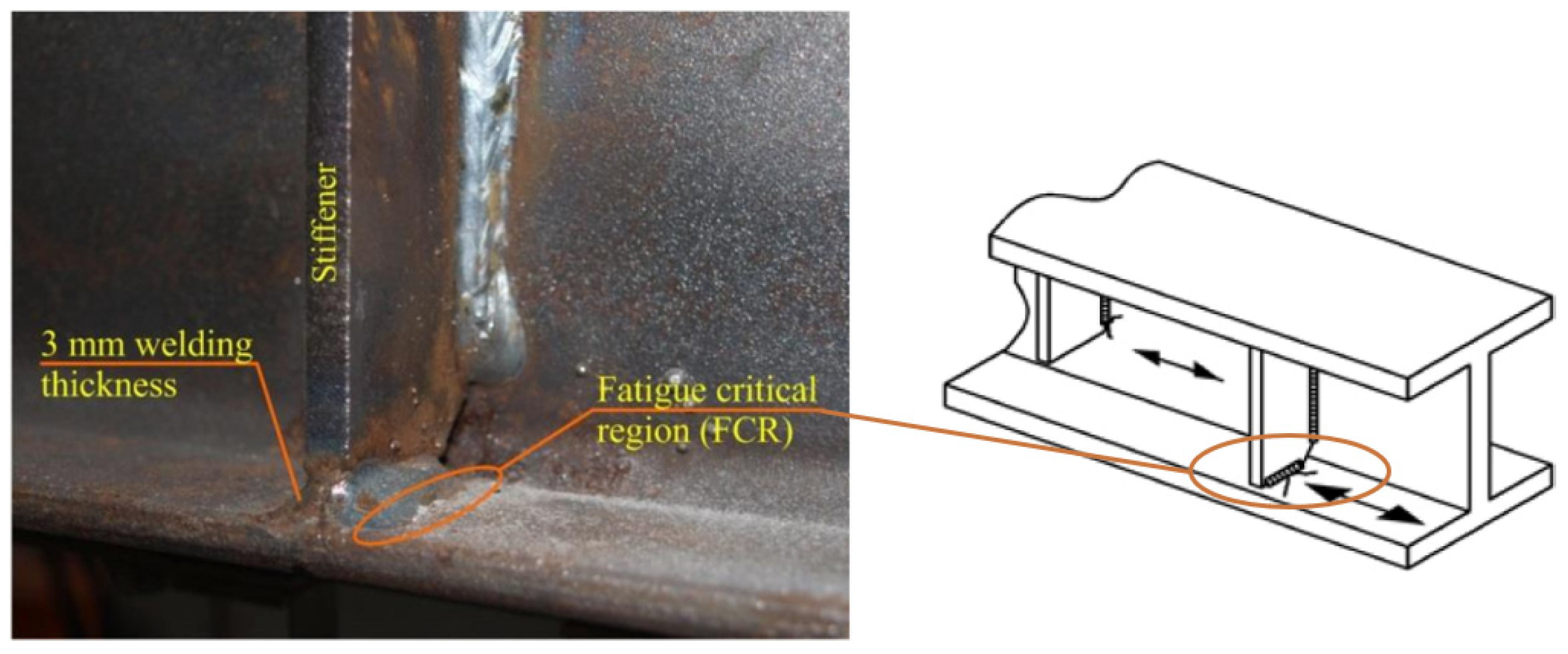
- The maximum top-flange fatigue stress range at the intermediate supports under fatigue truck loading was found to be 3.63 ksi. This condition is shown in Figure 3 in relation to the weld between the stiffener plate and the girder flange.
- The calculated factored fatigue stress ranges are well below the fatigue threshold of 10 ksi for AASHTO Category C or 12 ksi for Category C’ normally associated with such connections, shown in Figure 3. Therefore, fatigue is not likely to be a concern in the flanges themselves.
- Forces in the skewed end cross-frame members were also presented, providing data for future studies.
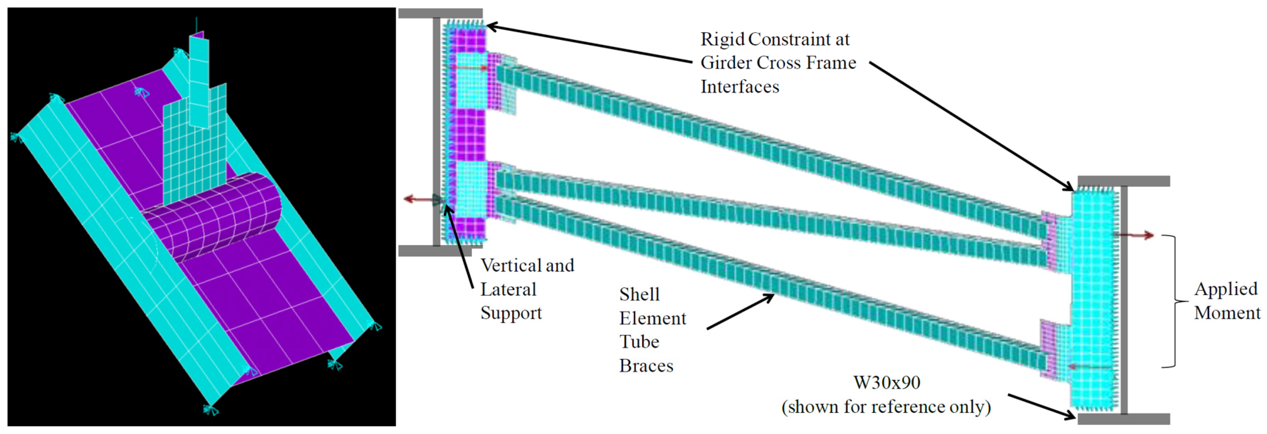
- A refined FE model of a skew connection of an end cross-frame to the steel girder was constructed to investigate the connection under fatigue loading. The maximum fatigue envelope force ranges were applied on this connection to study the stress concentration range and location of stress risers. The results show that a Half-Round Bearing Stiffener (HRBS) improves the stress distribution, especially when the stiffener plate is welded to the girder flanges. The stress concentration range calculated in the girder flange is around 18 to 50 percent lower for the HRBS connection compared to the bent plate connection for the welded and unwelded conditions, respectively. For the connection components, the maximum stress concentration range for the bent plate is 23.33 ksi, which is significantly higher than the maximum stress concentration range of 16.42 ksi for the stiffener plate connected to HRBS.
Author Contributions
Funding
Data Availability Statement
Acknowledgments
Conflicts of Interest
References
- U.S. Department of Transportation; Federal Highway Administration (FHWA). National Bridge Inventory; Federal Highway Administration (FHWA): Washington, DC, USA, 2022.
- AASHTO. AASHTO LRFD Bridge Design Specifications, 9th ed.; American Association of State Highway and Transportation Officials: Washington, DC, USA, 2020.
- Menassa, C.; Mabsout, M.; Tarhini, K.; Frederick, G. Influence of skew angle on reinforced concrete slab bridges. J. Bridge Eng. 2007, 12, 205–214. [Google Scholar] [CrossRef]
- Bishara, A.G.; Liu, M.C.; El-Ali, N.D. Wheel load distribution on simply supported skew I-beam composite bridges. J. Struct. Eng. 1993, 119, 399–419. [Google Scholar] [CrossRef]
- Rajagopalan, N. Bridge Superstructure; Alpha Science Int’l Ltd.: Oxford, UK, 2006. [Google Scholar]
- Wang, L. Cross-Frame and Diaphragm Behavior for Steel Bridges with Skewed Supports; University of Houston: Houston, TX, USA, 2002. [Google Scholar]
- Connor, R.J.; Lloyd, J.B. Maintenance Actions to Address Fatigue Cracking in Steel Bridge Structures; NCHRP Project; Transportation Research Board: Washington, DC, USA, 2017. [Google Scholar]
- Gunes, B.; Ilki, A.; Oztorun, N.K. Determination of Monitoring Parameters for Fatigue Behavior of Steel-Concrete Composite Bridge Girders with Welded Full Depth Transverse Stiffeners. Sustainability 2020, 12, 283. [Google Scholar] [CrossRef]
- Berglund, E.M.; Schultz, A.E. Girder differential deflection and distortion-induced fatigue in skewed steel bridges. J. Bridge Eng. 2006, 11, 169–177. [Google Scholar] [CrossRef]
- Connor, R.J.; Fisher, J.W. Identifying effective and ineffective retrofits for distortion fatigue cracking in steel bridges using field instrumentation. J. Bridge Eng. 2006, 11, 745–752. [Google Scholar] [CrossRef]
- Tabiatnejad, B.; Siddiqua, S.; Siemens, G. Impact of pore fluid salinity on the mechanical behavior of unsaturated bentonite–sand mixture. Environ. Earth Sci. 2016, 75, 1434. [Google Scholar] [CrossRef]
- Hartman, A.S.; Hassel, H.L.; Adams, C.A.; Bennett, C.R.; Matamoros, A.B.; Rolfe, S.T. Effects of cross-frame placement and skew on distortion-induced fatigue in steel bridges. Transp. Res. Rec. 2010, 2200, 62–68. [Google Scholar] [CrossRef]
- McConnell, J.R.; Almoosi, Y.S. Field Evaluation of Fatigue Stresses in a Modern Highly Skewed Steel I-Girder Bridge. J. Bridge Eng. 2022, 27, 4022005. [Google Scholar] [CrossRef]
- Tedesco, J.; Stallings, J.; Tow, D. Finite element method analysis of bridge girder-diaphragm interaction. Comput. Struct. 1995, 56, 461–473. [Google Scholar] [CrossRef]
- Dong, Z.-Q.; Li, G.; Li, H.-N. Dynamic tests of the collapse-prevention performance of a low-ductility low-rise steel concentrically braced frame. Eng. Struct. 2021, 240, 112420. [Google Scholar] [CrossRef]
- Schaefer, A.L. Crossframe Analysis of Highly-Skewed and Curved Steel I-Girder Bridges. Ph.D. Thesis, University of Colorado at Denver, Denver, CO, USA, 2012. [Google Scholar]
- Quadrato, C.; Wang, W.; Battistini, A.; Wahr, A.; Helwig, T.; Frank, K.; Engelhardt, M. Cross-Frame Connection Details for Skewed Steel Bridges; University of Texas at Austin, Center for Transportation Research: Austin, TX, USA, 2010. [Google Scholar]
- Astaneh-Asl, A.; Bolt, B.; McMullin, K.M.; Donikian, R.; Modjtahedi, D.; Cho, S. Seismic Performance of Steel Bridges during the 1994 Northridge Earthquake; University of California at Berkeley: Berkeley, CA, USA, 1994. [Google Scholar]
- Bruneau, M.; Wilson, J.C.; Tremblay, R. Performance of steel bridges during the 1995 Hyogo-ken Nanbu (Kobe, Japan) earthquake. Can. J. Civ. Eng. 1996, 23, 678–713. [Google Scholar] [CrossRef]
- Ballantyne, D.; Borcherdt, R.D.; Buckle, I.G.; O’Rourke, T.D.; Schiff, A.J. The Hanshin-Awaji Earthquake of January 17, 1995: Performance of Lifelines; National Center for Earthquake Engineering Research: Taipei, Taiwan, 1995.
- Carden, L.; Itani, A.; Buckle, I. An Experimental Study into the Distribution of Earthquake Forces in Steel Plate Girder Bridges. In Proceedings of the Pacific Conference on Earthquake Engineering, Christchurch, New Zealand, 13–15 February 2003. [Google Scholar]
- Kloiber, L.A. Orthogonal and Skewed Shear Connections—Design and Detailing Requirements; American Institute of Steel Construction (AISC): Chicago, IL, USA, 2004. [Google Scholar]
- Mehrabi, A.; Tabiatnejad, D.; Dolati, S.S.K. Connection Systems and Methods for Skewed Frames. U.S. Patents 11746484, 5 September 2023. [Google Scholar]
- Mehrabi, A.; Farhangdoust, S.; Dolati, S.S.K.; Tabiatnejad, D.; Lee, S.J.; Garber, D. Epoxy Dowel Pile Splice Evaluation; Research Center, Florida Department of Transportation: Tallahassee, FL, USA, 2022. [Google Scholar]
- G12.1—Guidelines for Design Constructability; AASHTO/NSBA Steel Bridge Collaboration: Chicago, IL, USA, 2003.
- Battistini, A.D.; Wang, W.; Helwig, T.A.; Engelhardt, M.D.; Frank, K.H. Stiffness behavior of cross frames in steel bridge systems. J. Bridge Eng. 2016, 21, 4016024. [Google Scholar] [CrossRef]
- Quadrato, C.; Battistini, A.; Helwig, T.; Engelhardt, M.; Frank, K. Increasing Girder Elastic Buckling Strength Using Split Pipe Bearing Stiffeners. J. Bridge Eng. 2014, 19, 4013017. [Google Scholar] [CrossRef]
- mBrace3D, 2.0; Nessos Information Technologies SA: Athens, Greece, 2023.
- MIDAS. MIDAS Civil (Software), MIDAS IT: Seongnam, Republic of Korea, 2024.
- Reichenbach, M.; White, J.; Park, S.; Zecchin, E.; Moore, M.; Liu, Y.; Liang, C.; Kövesdi, B.; Helwig, T.; Engelhardt, M. Proposed Modification to AASHTO Cross-Frame Analysis and Design; National Academies of Sciences, Engineering, and Medicine: Washington, DC, USA, 2021. [Google Scholar]
- Gull, J.H.; Azizinamini, A.; Helwig, T.A. Comparison of detailing methods for straight skewed steel I-girder bridges. J. Constr. Steel Res. 2017, 136, 24–34. [Google Scholar] [CrossRef]
- Horas, C.S.; De Jesus, A.M.; Calçada, R. Efficient progressive global-local fatigue assessment methodology for existing metallic railway bridges. J. Constr. Steel Res. 2022, 196, 107431. [Google Scholar] [CrossRef]
- Horas, C.S.; De Jesus, A.M.; Ribeiro, D.; Calçada, R. Efficient multiscale methodology for local stress analysis of metallic railway bridges based on modal superposition principles. Eng. Fail. Anal. 2022, 138, 106391. [Google Scholar] [CrossRef]
- De Jesus Abílio, M.; Rui, C. Efficient computational approach for fatigue assessment of riveted connections. J. Constr. Steel Res. 2019, 153, 1–18. [Google Scholar]
- Albuquerque, C.; Silva, A.L.; de Jesus, A.M.; Calçada, R. An efficient methodology for fatigue damage assessment of bridge details using modal superposition of stress intensity factors. Int. J. Fatigue 2015, 81, 61–77. [Google Scholar] [CrossRef]
- Correia, J.A.; da Silva, A.L.; Xin, H.; Lesiuk, G.; Zhu, S.-P.; de Jesus, A.M.; Fernandes, A.A. Fatigue performance prediction of S235 base steel plates in the riveted connections. In Structures; Elsevier: Amsterdam, The Netherlands, 2021; pp. 745–755. [Google Scholar]
- Aygül, M.; Al-Emrani, M.; Barsoum, Z.; Leander, J. Investigation of distortion-induced fatigue cracked welded details using 3D crack propagation analysis. Int. J. Fatigue 2014, 64, 54–66. [Google Scholar] [CrossRef]
- AWS D1. 1/D1. 1M; Structural Welding Code Steel. American Welding Society: Miami, FL, USA, 2020.


| Bridge Number | Span Length (ft) | Skew Angle at Pier (Degree) | Curvature | ||||||||||
|---|---|---|---|---|---|---|---|---|---|---|---|---|---|
| Span 1 | Span 2 | Span 3 | Span 4 | SUM | Bent/ Pier 1 | Bent/ Pier 2 | Bent/ Pier 3 | Bent/ Pier 4 | Bent/ Pier 5 | θ | R (ft) | L/R | |
| 1 | 190 | 140 | - | - | 330 | 52.8 | 56.1 | 57.2 | - | - | 1°44′46″ | 3281.4 | 0.058 |
| 2 | 204 | 160 | - | - | 364 | 56.2 | 56.2 | 56.2 | - | - | - | - | 0 |
| 3 | 123 | 137 | - | - | 260 | 23.0 | 23.0 | 23.0 | - | - | - | - | 0 |
| 4 | 217 | 234 | - | - | 450 | 39.8 | 39.8 | 39.8 | - | - | - | - | 0 |
| 5 | 210 | 234 | - | - | 445 | 36.1 | 39.2 | 42.7 | - | - | 1°30′0″ | 3819.7 | 0.061 |
| 6 | 186 | 167 | 156 | - | 509 | 40.8 | 27.0 | 0.0 | 0.0 | - | 4°45′0″ | 738.2 | 0.252 |
| 7 | 218 | 250 | - | - | 468 | 40.6 | 45.0 | 45.0 | - | - | 1°59′59″ | 2865.0 | 0.087 |
| 8 | 187 | 154 | 149 | - | 491 | 41.1 | 50.9 | 34.7 | 0.0 | - | 5° | 1145.9 | 0.163 |
| 9 | 159 | 239 | 235 | 176 | 809 | 0.0 | 57.0 | 50.5 | 39.7 | 0.0 | 8°14′38″ | 695.0 | 0.344 |
| 10 | 198 | 213 | - | - | 411 | 44.1 | 48.7 | 46.8 | - | - | 7°04′25″ | 810.0 | 0.263 |
| 11 | 172 | 253 | 253 | 202 | 880 | 0.0 | 50.1 | 50.1 | 50.1 | 0.0 | - | - | 0 |
| 12 | 189 | 157 | 159 | 228 | 732 | 53.0 | 36.0 | 8.0 | 45.0 | 45.0 | 15°34′32″ | 5725.1 | 0.040 |
| 13 | 156 | 145 | - | - | 301 | 40.5 | 40.5 | 40.5 | - | - | - | - | 0 |
| 14 | 172 | 172 | - | - | 343 | 55.0 | 55.0 | 55.0 | - | - | - | - | 0 |
| 15 | 262 | 255 | - | - | 517 | 52.2 | 53.3 | 54.7 | - | - | 0°29′14″ | 11,758.0 | 0.022 |
| 16 | 178 | 178 | - | - | 355 | 25.6 | 25.6 | 25.6 | - | - | - | - | 0 |
| 17 | 253 | 253 | - | - | 505 | 50.4 | 50.4 | 50.4 | - | - | - | - | 0 |
| 18 | 252 | 252 | - | - | 503 | 50.2 | 50.2 | 50.2 | - | - | - | - | 0 |
| 19 | 149 | 174 | - | - | 323 | 23.4 | 23.4 | 23.4 | - | - | - | - | 0 |
| 20 | 230 | 210 | - | - | 440 | 43.8 | 43.8 | 43.8 | - | - | - | - | 0 |
| 21 | 208 | 209 | - | - | 416 | 36.7 | 36.0 | 35.3 | - | - | - | - | 0 |
| 22 | 170 | 170 | - | - | 340 | 52.7 | 52.7 | 52.7 | - | - | - | - | 0 |
| 23 | 199 | 199 | - | - | 398 | 54.5 | 54.5 | 54.5 | - | - | - | - | 0 |
| 24 | 181 | 174 | - | - | 355 | 25.0 | 0.0 | 25.0 | - | - | 1°48′ | 3183.1 | 0.057 |
| 25 | 167 | 185 | - | - | 353 | 35.5 | 35.5 | 35.6 | - | - | - | - | 0 |
| 26 | 204 | 196 | 185 | - | 585 | 44.2 | 44.7 | 58.7 | 58.7 | - | - | - | 0 |
| Bridge Number | Girder Spacing (in.) | No. of Lanes | No. of Girders | Deck Width (ft) | wg (ft) | Skew Index (Is) Is = wg · tan q/Ls | Max Skew Index (Is) | End Cross-Frame Type | |||
|---|---|---|---|---|---|---|---|---|---|---|---|
| Span 1 | Span 2 | Span 3 | Span 4 | ||||||||
| 1 | 123 | 3 | 6 | 58.2 | 51.3 | 0.40 | 0.57 | - | - | 0.57 | Inverted-V |
| 2 | 114 | 3 | 6 | 54.3 | 47.5 | 0.35 | 0.44 | - | - | 0.44 | Inverted-V |
| 3 | 120 | 2 | 4 | 37.1 | 30.0 | 0.10 | 0.09 | - | - | 0.10 | V |
| 4 | 144 | 3 | 5 | 56.1 | 48.0 | 0.18 | 0.17 | - | - | 0.18 | V |
| 5 | 144 | 4 | 6 | 67.1 | 60.0 | 0.23 | 0.24 | - | - | 0.24 | V |
| 6 | 150 | 2 | 4 | 48.4 | 37.4 | 0.17 | 0.11 | - | - | 0.17 | V |
| 7 | 132 | 1 | 3 | 30.1 | 22.0 | 0.10 | 0.09 | - | - | 0.10 | Inverted-V |
| 8 | 111 | 2 | 5 | 43.1 | 37.0 | 0.24 | 0.29 | 0.17 | - | 0.29 | V |
| 9 | 144 | 1 | 4 | 44.0 | 36.0 | 0.35 | 0.23 | 0.19 | 0.17 | 0.35 | Inverted-V |
| 10 | 116 | 1 | 4 | 37.3 | 29.0 | 0.17 | 0.15 | - | - | 0.17 | Inverted-V |
| 11 | 144 | 2 | 4 | 43.1 | 36.0 | 0.25 | 0.17 | 0.17 | 0.21 | 0.25 | V |
| 12 | 148 | 3 | 5 | 60.2 | 49.2 | 0.35 | 0.23 | 0.31 | 0.22 | 0.35 | Inverted-V |
| 13 | 117 | 2 | 5 | 47.1 | 39.0 | 0.21 | 0.23 | - | - | 0.23 | V |
| 14 | 150 | 2 | 4 | 47.1 | 37.5 | 0.31 | 0.31 | - | - | 0.31 | Inverted-V |
| 15 | 144 | 2 | 4 | 43.1 | 36.0 | 0.18 | 0.20 | - | - | 0.20 | Inverted-V |
| 16 | 161 | 2 | 4 | 50.2 | 40.3 | 0.11 | 0.11 | - | - | 0.11 | Inverted-V |
| 17 | 140 | 2 | 6 | 65.0 | 58.3 | 0.28 | 0.28 | - | - | 0.28 | Inverted-V |
| 18 | 153 | 2 | 5 | 59.0 | 51.0 | 0.24 | 0.24 | - | - | 0.24 | Inverted-V |
| 19 | 160 | 4 | 8 | 101.1 | 93.3 | 0.27 | 0.23 | - | - | 0.27 | Inverted-V |
| 20 | 127 | 4 | 7 | 71.1 | 63.4 | 0.26 | 0.29 | - | - | 0.29 | Inverted-V |
| 21 | 127 | 3 | 6 | 59.1 | 52.9 | 0.19 | 0.18 | - | - | 0.19 | Inverted-V |
| 22 | 97 | 2 | 7 | 55.3 | 48.3 | 0.37 | 0.37 | - | - | 0.37 | Inverted-V |
| 23 | 141 | 2 | 4 | 43.1 | 35.3 | 0.25 | 0.25 | - | - | 0.25 | Inverted-V |
| 24 | 96 | 1 | 4 | 30.1 | 24.0 | 0.06 | 0.06 | - | - | 0.06 | Inverted-V |
| 25 | 108 | 3 | 6 | 54.4 | 45.1 | 0.19 | 0.17 | - | - | 0.19 | Inverted-V |
| 26 | 105 | 2 | 5 | 42.5 | 35.0 | 0.17 | 0.29 | 0.31 | - | 0.31 | Inverted-V |
| Case Name | Rigid Supports | Neoprene Bearings | Piers Modeled |
|---|---|---|---|
| Case A | ✓ * | - | - |
| Case B | - | ✓ | - |
| Case C | - | ✓ | ✓ |
| Case | 1 Plate: Deck, Girder Web, and Flanges Beam: Cross-Frames | 2 Plate: Deck and Girder Web Beam: Girder Flange & Cross-Frames |
|---|---|---|
| A Simple Rigid Support | 1.45 | 1.22 |
| B Neoprene Bearing | 1.39 | 1.44 |
| C Piers Modeled | 1.40 | 1.57 |
| Material | Strength (ksi) | Modulus of Elasticity (kips/in2) | Poisson’s Ratio | Weight Density (kips/ft3) | Damping Ratio |
|---|---|---|---|---|---|
| Steel | Fy = 50 | 2.90 × 10⁴ | 0.3 | 0.49 | 0.02 |
| Concrete | f′c = 4.5 | 3.86 × 10³ | 0.2 | 0.15 | 0.05 |
| Bridge Number | Maximum Top-Flange Fatigue Stress Range (ksi) | Bridge Number | Maximum Top-Flange Fatigue Stress Range (ksi) |
|---|---|---|---|
| 1 | 2.23 | 14 | 2.53 |
| 2 | 1.24 | 15 | 2.42 |
| 3 | 1.60 | 16 | 1.84 |
| 4 | 1.70 | 17 | 2.04 |
| 5 | 1.93 | 18 | 1.46 |
| 6 | 2.86 | 19 | 2.17 |
| 7 | 3.63 | 20 | 2.76 |
| 8 | 3.17 | 21 | 2.48 |
| 9 | 2.84 | 22 | 1.66 |
| 10 | 3.14 | 23 | 3.13 |
| 11 | 1.94 | 24 | 3.57 |
| 12 | 2.40 | 25 | 2.90 |
| 13 | 2.35 | 26 | 2.79 |
| Bridge Number | Top Chord Force (ksi) | Diagonal Elements Force (ksi) | Bottom Chord Force (ksi) | |||
|---|---|---|---|---|---|---|
| Min | Max | Min | Max | Min | Max | |
| 1 | −7.6 | 14.0 | −15.8 | 4.7 | −8.8 | 10.5 |
| 2 | −8.9 | 10.3 | −19.5 | 8.3 | −11.5 | 18.0 |
| 3 | −4.5 | 16.2 | −8.0 | 4.9 | −4.4 | 26.2 |
| 4 | −6.8 | 15.9 | −6.0 | 5.6 | −17.4 | 14.5 |
| 5 | −9.5 | 19.6 | −5.7 | 5.7 | −10.7 | 12.4 |
| 6 | −8.5 | 16.2 | −6.0 | 6.1 | −17.4 | 25.6 |
| 7 | −18.6 | 12.7 | −12.5 | 9.1 | −32.1 | 36.5 |
| 8 | −4.8 | 17.1 | −3.8 | 3.8 | −11.4 | 13.9 |
| 9 | −6.6 | 12.6 | −20.3 | 6.3 | −25.1 | 36.1 |
| 10 | −6.5 | 7.7 | −10.3 | 9.8 | −13.7 | 21.1 |
| 11 | −11.7 | 20.8 | −12.8 | 12.2 | −22.3 | 27.5 |
| 12 | −7.1 | 16.1 | −20.2 | 4.9 | −9.2 | 16.1 |
| 13 | −6.2 | 18.8 | −9.0 | 6.6 | −8.9 | 13.2 |
| 14 | −7.6 | 14.2 | −26.1 | 7.8 | −9.4 | 20.9 |
| 15 | −4.6 | 8.5 | −24.5 | 7.4 | −18.1 | 23.4 |
| 16 | −6.3 | 17.0 | −15.3 | 2.9 | −5.2 | 12.4 |
| 17 | −5.2 | 9.2 | −14.7 | 5.1 | −7.1 | 8.8 |
| 18 | −6.0 | 11.5 | −12.6 | 4.0 | −8.8 | 9.9 |
| 19 | −8.3 | 13.4 | −13.8 | 5.5 | −2.9 | 10.9 |
| 20 | −5.8 | 11.9 | −11.7 | 3.0 | −2.1 | 7.2 |
| 21 | −7.0 | 11.0 | −14.2 | 5.2 | −11.2 | 12.0 |
| 22 | −5.1 | 8.9 | −15.5 | 4.1 | −4.3 | 8.8 |
| 23 | −9.4 | 11.0 | −16.9 | 7.1 | −8.8 | 13.8 |
| 24 | −13.0 | 10.0 | −11.0 | 3.6 | −8.9 | 12.5 |
| 25 | −9.7 | 10.4 | −11.3 | 4.6 | −8.2 | 9.0 |
| 26 | −7.7 | 9.7 | −12.4 | 10.3 | −13.2 | 16.9 |
| Weld Condition | Skewed Connection Type | Maximum Principal Stress Concentration Range and Position in Steel I-Girder | Maximum Principal Stress Concentration Range and Position in Stiffener Plate | Maximum Principal Stress Concentration Range and Position in Skewed Connection |
|---|---|---|---|---|
| Unwelded | Half-Round Bearing Stiffener | 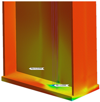 | 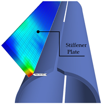 |  |
| Max SCR = 2.62 (ksi) | Max SCR = 16.42 (ksi) | Max SCR = 14.71 (ksi) | ||
| Welded | Half-Round Bearing Stiffener | 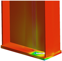 | 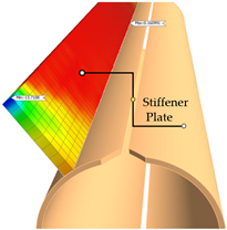 | 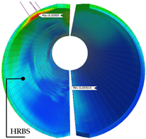 |
| Max SCR = 4.33 (ksi) | Max SCR = 13.71 (ksi) | Max SCR = 8.00 (ksi) | ||
| Welded | Bent Plate | 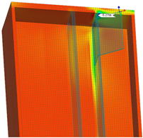 | 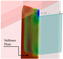 | 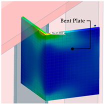 |
| Max SCR = 5.27 (ksi) | Max SCR = 9.19 (ksi) | Max SCR = 23.33 (ksi) |
Disclaimer/Publisher’s Note: The statements, opinions and data contained in all publications are solely those of the individual author(s) and contributor(s) and not of MDPI and/or the editor(s). MDPI and/or the editor(s) disclaim responsibility for any injury to people or property resulting from any ideas, methods, instructions or products referred to in the content. |
© 2024 by the authors. Licensee MDPI, Basel, Switzerland. This article is an open access article distributed under the terms and conditions of the Creative Commons Attribution (CC BY) license (https://creativecommons.org/licenses/by/4.0/).
Share and Cite
Tabiatnejad, D.; Khedmatgozar Dolati, S.S.; Mehrabi, A.; Helwig, T.A. Fatigue Consideration for Tension Flange over Intermediate Support in Skewed Continuous Steel I-Girder Bridges. Infrastructures 2024, 9, 99. https://doi.org/10.3390/infrastructures9070099
Tabiatnejad D, Khedmatgozar Dolati SS, Mehrabi A, Helwig TA. Fatigue Consideration for Tension Flange over Intermediate Support in Skewed Continuous Steel I-Girder Bridges. Infrastructures. 2024; 9(7):99. https://doi.org/10.3390/infrastructures9070099
Chicago/Turabian StyleTabiatnejad, Dariya, Seyed Saman Khedmatgozar Dolati, Armin Mehrabi, and Todd A. Helwig. 2024. "Fatigue Consideration for Tension Flange over Intermediate Support in Skewed Continuous Steel I-Girder Bridges" Infrastructures 9, no. 7: 99. https://doi.org/10.3390/infrastructures9070099
APA StyleTabiatnejad, D., Khedmatgozar Dolati, S. S., Mehrabi, A., & Helwig, T. A. (2024). Fatigue Consideration for Tension Flange over Intermediate Support in Skewed Continuous Steel I-Girder Bridges. Infrastructures, 9(7), 99. https://doi.org/10.3390/infrastructures9070099