Article

The Potential of One-Sided Traditional Windcatchers for Outdoor Use as a Sustainable Urban Feature

by
Hossein Ghandi
* and
Mattia Federico Leone
LUPT-PLINIVS Study Centre, University of Napoli Federico II, NA 80134 Naples, Italy
*
Author to whom correspondence should be addressed.
Urban Sci. 2024, 8(4), 229; https://doi.org/10.3390/urbansci8040229
Submission received: 7 October 2024 / Revised: 22 November 2024 / Accepted: 27 November 2024 / Published: 28 November 2024

Abstract

:
Urbanization is exacerbating heat islands, causing adverse effects on life and health, including thermal stress. This highlights the importance of using natural resources for thermal regulation, particularly through historically employed passive strategies. Windcatchers have traditionally been installed in arid and hot areas to provide thermal comfort (TC), especially in indoor spaces. However, despite significant internal shape development, a notable gap remains in exploring their outdoor applications. This paper investigates a new integrated design for a one-sided windcatcher, which captures wind through a single inlet by combining traditional principles with modern sustainable features, such as green façade, to enhance outdoor urban space. The design concept was developed in two stages: the “Initial Design Step” and the “Geometrical Assessment”, utilizing iterative computational fluid dynamics (CFD) simulations. This study aimed to evaluate the potential of windcatchers for outdoor applications using an upstream, curved shaft and guide vanes, tested at wind velocities of 1.5 m/s for a 5 m high windcatcher and 4 m/s for a 10 m high windcatcher. The study revealed a meaningful relationship among the parameters, as they influence each other. Achieving optimal performance requires careful control of the parameters, such as balancing the inner wall curvature and inlet size to optimize airflow dynamics. In urban contexts, turbulence and morphology affect airflow but can be mitigated through regionally tailored windcatcher designs. Nevertheless, several critical research gaps remain, highlighting the windcatcher’s potential for improvement and the need for further investigation in future studies.

1. Introduction

Nowadays, urbanization is rapidly increasing due to population growth, leading to a higher demand for energy. The International Energy Agency (IEA) [1] analysis showed that energy-related CO2 emissions rose by 1.1% in 2023 to 37.4 billion tones, exacerbating global warming. In addition, poor city management and excessive use of carbon-intensive heating, ventilation, and air conditioning (HVAC) systems amplify the effect of an urban heat island (UHI) [2,3]. It also negatively impacts the quality of life for city dwellers by causing thermal discomfort, heat disorders, and ecological changes [4]. This outlines the significance of adaption and mitigation strategies to deal with UHI and provide both indoor air quality (IAQ) and outdoor thermal comfort (OTC). Although IAQ due to advancement in technology is facilitated, reaching OTC still takes a long way to go [5]; thus, it has become a central focus of scientists and researchers [3]. Additionally, improving OTC is complicated since it depends on a comprehensive understanding of microclimate conditions because of varying environmental perceptions. Microclimate, defined as the climate near the ground [6], is influenced by several factors such as individual building envelopes and urban morphology [2,4] (Figure 1). These factors also impact energy demands and thermal conditions at any location [7]. To remedy this, passive mitigation and adaptation strategies, including climate-responsive designs such as orienting streets to the prevailing wind direction, demonstrate the potential to reduce the impact of urban heat islands (UHIs) and the equivalent temperature perceived by people [8]. These strategies also alleviate thermal loads [2], leading to an enhanced TC, long-term resilience, and sustainability. For instance, during hot summer months, people prefer higher wind velocities, such as sea breezes, and seek shade under canopies, buildings, and trees, as shaded surfaces are cooler due to reduced sun exposure [9,10]. Additionally, they tend to stay near vegetation, which helps lower temperatures through evapotranspiration [11]. These factors collectively contribute to TC, defined as the “state of mind that expresses satisfaction with the thermal surroundings” [12].
Remarkably, humans have historically developed ways to leverage natural resources, such as wind, in innovative ways to regulate climatic conditions to naturally ventilate spaces, especially in hot climates [13]. Undoubtedly, one of the most sophisticated techniques is the windcatcher. It exemplifies architectural features that harmonize human-created environments with nature [14,15] and is ingeniously customized to suit local climatic conditions [16]. Windcatchers are recognized as a passive cooling design that operates without energy consumption and significantly reduces the cooling energy load [17]. This highlights the importance of minimizing reliance on energy-intensive HVAC systems.

1.1. Windcatcher: From Vernacular Architecture to Contemporary Applications

A windcatcher (or “Badgir” in Persian) is a tower mounted on the roof of a building, typically consisting of an inlet to catch air, a vertical shaft to channel it, and an outlet to expel it [18]. Its continuous operation is driven by two primary factors: wind force due to air pressure, and buoyancy caused by temperature differences between the inside and the outside [19]. Windcatchers come in various forms, differing in tower height, cross-section, and the number of openings [20]. These variations are influenced by environmental conditions and the architect’s preferences. For example, in the Persian Gulf region, windcatchers incorporate water and evaporative cooling technology, such as underground water canals known as ‘Qanat’ or ‘Naghab’ (Figure 2) [21,22]. Windcatchers are further categorized into two main groups: unidirectional and bidirectional [23]. These categories vary in the number of openings to suit the climate conditions of the area and ensure compatibility with periodic changes in prevailing winds [21,24]. This underscores their scalability and adaptability to diverse environmental conditions [25].
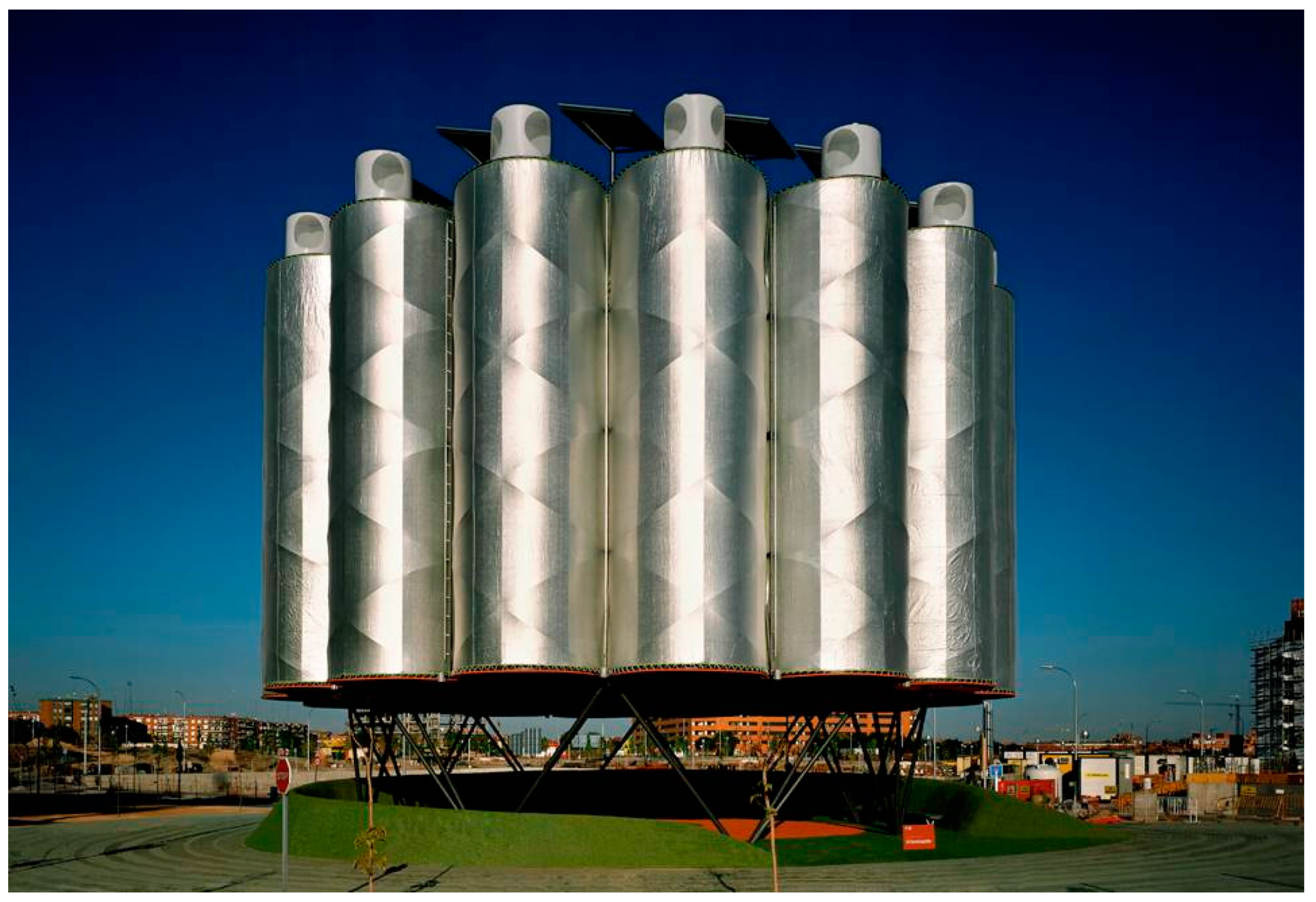
Nowadays, windcatchers are enhanced in their design and performance by integrating traditional shapes with modern devices, as exemplified by the Visitor Center at Zion National Park in the US [26]. In urban settings, a notable modern example is the wind tower in Masdar City, designed by Foster + Partners. This innovative structure incorporates advanced technology to control the orientation of inlet louvers based on wind direction, and utilizes mist jets to enhance air quality [27]. As another example, the “Air Trees” designed by Ecosistema Urbano [28] (Figure 3) Office Architects consist of sixteen metallic wind towers evenly distributed around its external perimeter [29]. Each wind tower is equipped with three cylinders containing electric fans to facilitate evaporative cooling ventilation. Additionally, six nozzles positioned just below the windcatcher section redirect the airflow toward the pedestrian area [30].

1.2. Windcatcher’s Challenges

The airflow circulation inside a windcatcher is a complex phenomenon influenced by various external and internal factors, resulting in flow separation, recirculation, reattachment, and secondary swirling flows [18,31,32]. As depicted in Figure 4, at the 90-degree bend, the air undergoes a sudden change in direction, leading to a centrifugal force that pushes the flow toward the outer wall of the bend. This creates a significant pressure gradient between the inner and outer walls, causing flow separation and the formation of a recirculation zone due to the lower momentum of fluid near the inner wall [18,33]. This tendency of airflow moving toward the outer wall extends the recirculation zone, leading to increased flow losses and reduced performance of windcatchers. Therefore, frictional and dynamic losses are crucial factors to consider as they directly impact the efficiency of windcatchers. In recent years, numerous studies have aimed to address these challenges and enhance windcatcher performance, as summarized in a non-exhaustive review in Table A1.
In urban contexts, windcatcher performance is significantly influenced by the surrounding morphology [19,34], which affects the air mass by reducing its velocity and altering its direction [35]. This influence is particularly notable at the level of the urban canopy layer (UCL), which spans between ground level and the average height of buildings [36]. Morphological configurations can have both positive and negative effects on the performance of windcatchers. For instance, the wind channel phenomenon can be utilized to accelerate wind towards openings [37], while low-velocity regions created by obstacles can diminish the induced airflow rate [38]. According to Nejat et al. [38], even at low wind velocities, windcatchers are potential architectural elements that can enhance IAQ and TC in diverse regions. Several studies have been conducted to assess the influence of external factors on windcatcher performance, summarized in a non-exhaustive review in Table A2.

2. Materials and Methods

2.1. Research Gap and Scopes

Previous research has extensively studied windcatcher geometry and design parameters such as the cross-section, internal partitions, openings, height, roof design, louvers, and dampers. However, fewer investigations have evaluated the impact of external design factors on windcatcher efficiency, such as upstream objects [13]. Despite technological advancements leading to improvements, most studies still primarily focus on their performance in indoor space ventilation. Consequently, there remain several unexplored areas in the application of windcatchers in outdoor environments and their interaction with external factors.
In this study, an innovative approach is proposed to utilize traditional windcatchers, addressing a significant gap in current outdoor research. Our proposal involves employing windcatchers as passive outdoor ventilators integrated with blue and green features. Our objectives were twofold: to uphold the inherent environmental sustainability of this technology and to explore novel applications. Additionally, we aimed to demonstrate how this distinctive architectural feature and time-honored design can be creatively adapted to meet contemporary needs, thereby promoting healthier and more sustainable living environments. The focus of this paper is centered on assessing the performance of a one-sided windcatcher to evaluate feasibility and potential future advancements. To achieve this, the research objectives were structured into two main steps:
(a)
Initial Design Step: During this phase, the theoretical concept was defined, emphasizing the development and interpretation of both geometric and sustainable attributes. This process involved establishing foundational design principles and features, while also identifying key parameters essential to design.
(b)
Geometrical Assessment: This phase entailed evaluating the designed geometry and its associated parameters through an iterative process involving multiple sequential steps. This encompassed creating the geometry using Rhinoceros 7 (McNeel), conducting computational fluid dynamics (CFD) simulations in ANSYS to assess its performance, and subsequently analyzing the outcomes to refine and finalize the design.

2.2. Design Concept and Principles

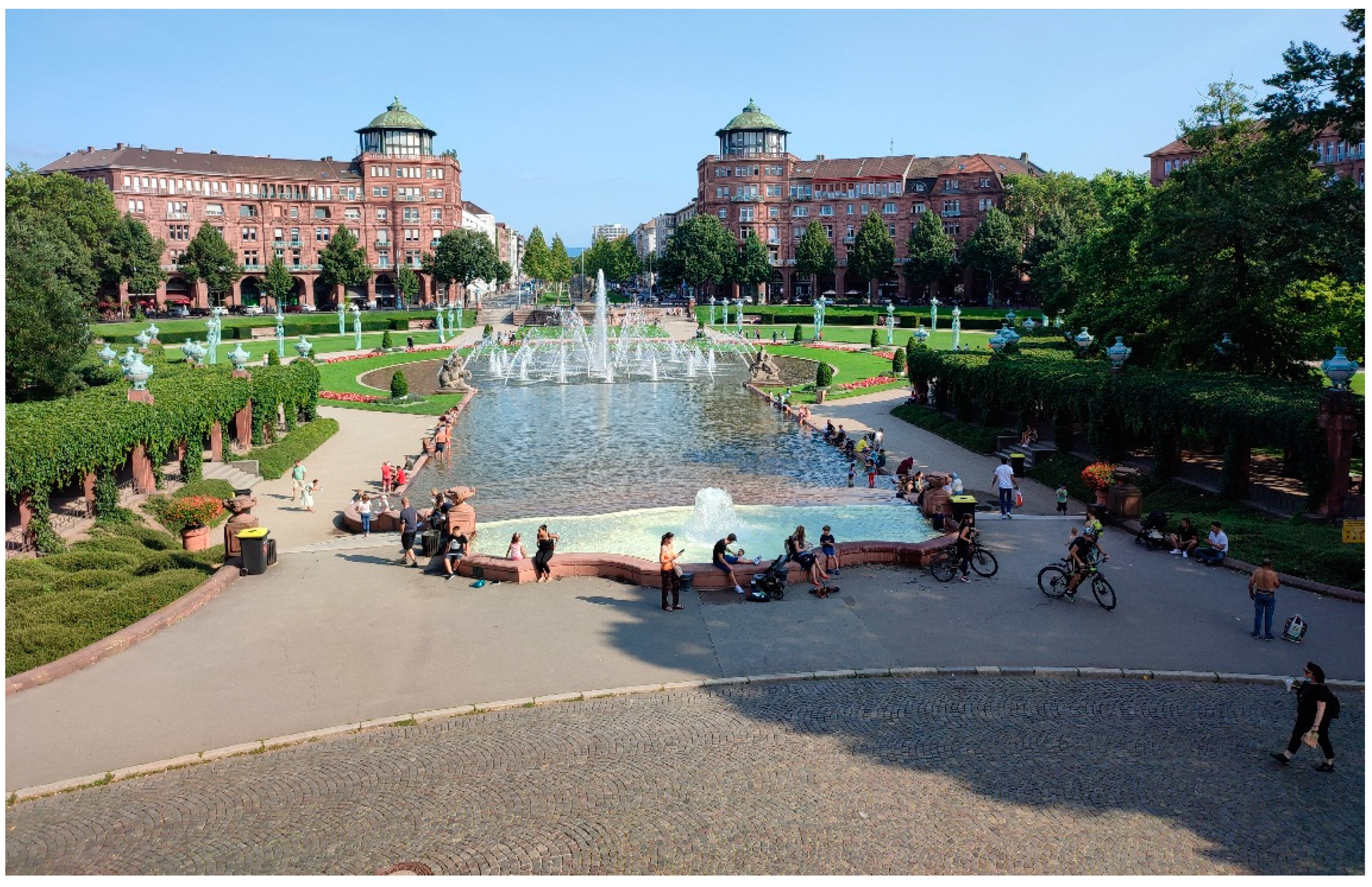
TC is influenced by various factors, encompassing environmental, spatial, physiological, and psychological aspects. The human body demonstrates remarkable adaptability in maintaining its homeostasis. Adaptation can be classified into reactive and interactive acclimatization, where reactive adjustments are personal and interactive adaptations involve changes in the environment. These adaptations encompass both conscious and subconscious adjustments to the surroundings, enabling individuals to thrive and respond uniquely to extreme environments and changing conditions (Figure 5) [39]. Air temperature, wind velocity, and humidity collectively influence how humans perceive the outdoor environment, shaping what is commonly referred to as the “feels like” temperature. This concept integrates factors such as wind chill temperature to accurately represent the combined effect of these variables [40]. For instance, sweating is a biophysical function considered a natural response of our body to regulate abnormal internal temperatures, facilitating cooling through convective heat dissipation [10,41]. This process is highly influenced by the surrounding wind velocity. In hot and humid environments, a high airflow velocity accelerates the evaporation of sweat and enhances moisture removal by displacing saturated air from the skin with unsaturated air [42]. To sum up, higher wind speeds are generally associated with improved thermal comfort, particularly in humid climates, as they enhance the body’s cooling process through faster heat dissipation, provided they do not exceed comfortable levels.
On the other hand, windcatchers can capture high-velocity winds, particularly when compared to those at the street level, resulting in purer air with reduced dust and pollution. It is important to note that their effectiveness is directly dependent on their height, typically ranging from 2 to 20 m above the building roof [43].
These correlations raise several questions:
(a)
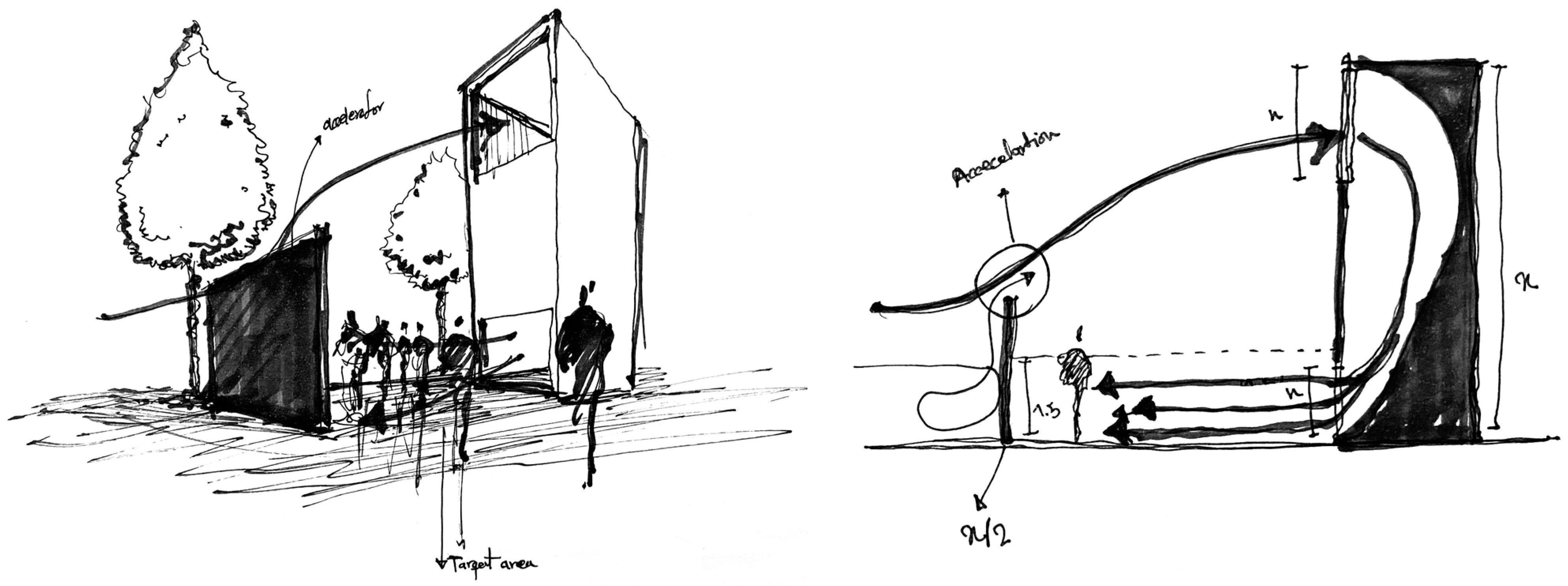
How effective would it be to design windcatchers at the street level as urban public facilities (urban furniture) to capture higher air velocities present above the street level and direct them downward? This could accelerate heat dissipation on pedestrians’ skin by directing induced airflow toward them (Figure 6).
(b)
How could incorporating blue and green features enhance the public space surrounding windcatchers?
(c)
How can the windcatcher design be made adaptable to fit into various urban contexts with different site restrictions, such as obstacles like trees?
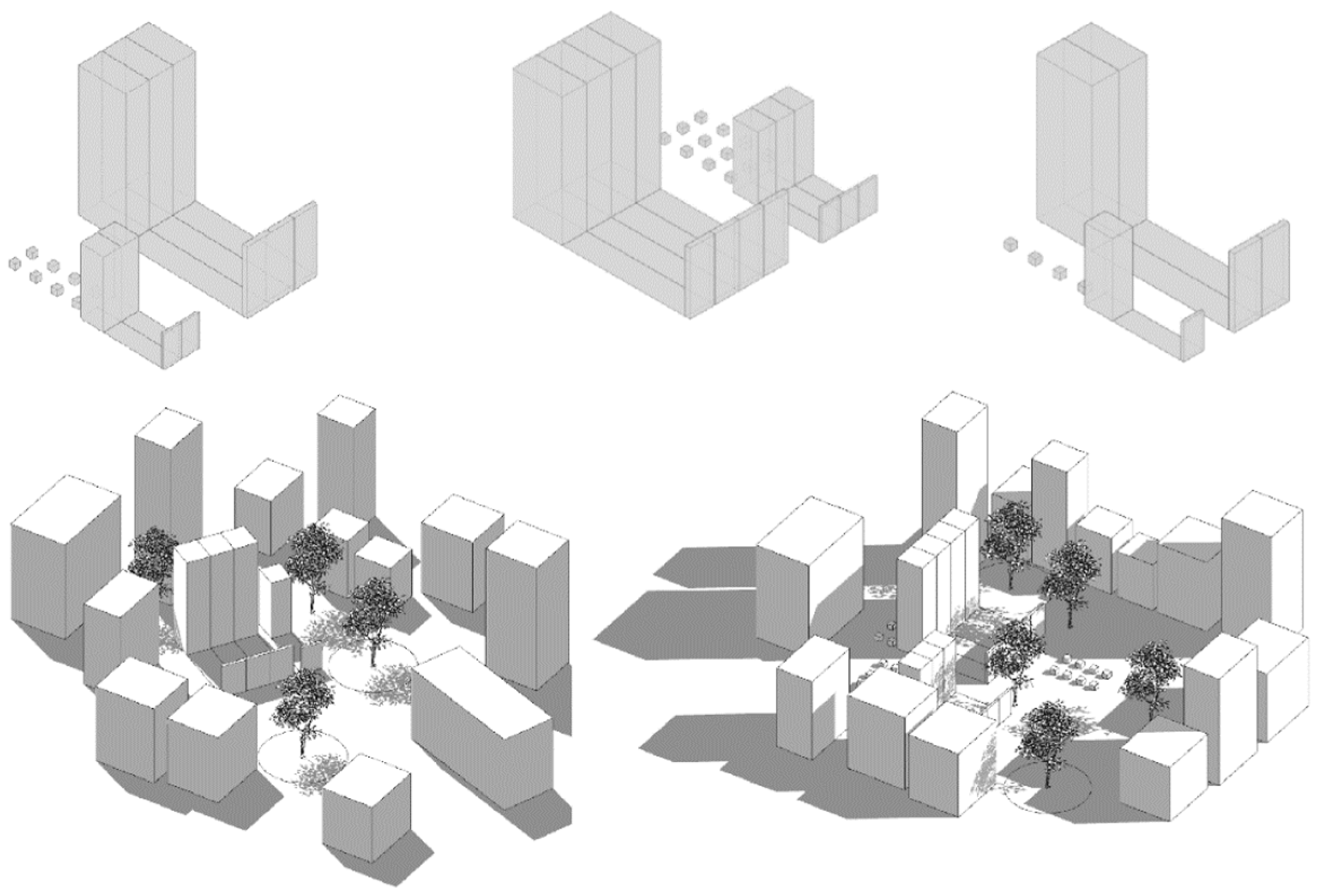
To address the design questions, the windcatcher is conceived as a modular element that can be assembled in various configurations based on the dimensions of the project site, surrounding urban morphology, and potential obstructions (Figure 7). Each module incorporates a variety of green and blue features aimed at enhancing passive cooling performance and contributing to the overall aesthetic appeal in public spaces (Figure A1). In terms of adaptability, the incorporation of green and blue features is tailored to meet the specific requirements of the area (Figure 8a). For seasonal functional adaptation, during winter, when cold and harsh winds prevail, the openings of the windcatchers can be closed to prevent the channeling of cold winds while surfaces are kept dry. This adjustment provides perceived shelter for pedestrians (Figure 8b).
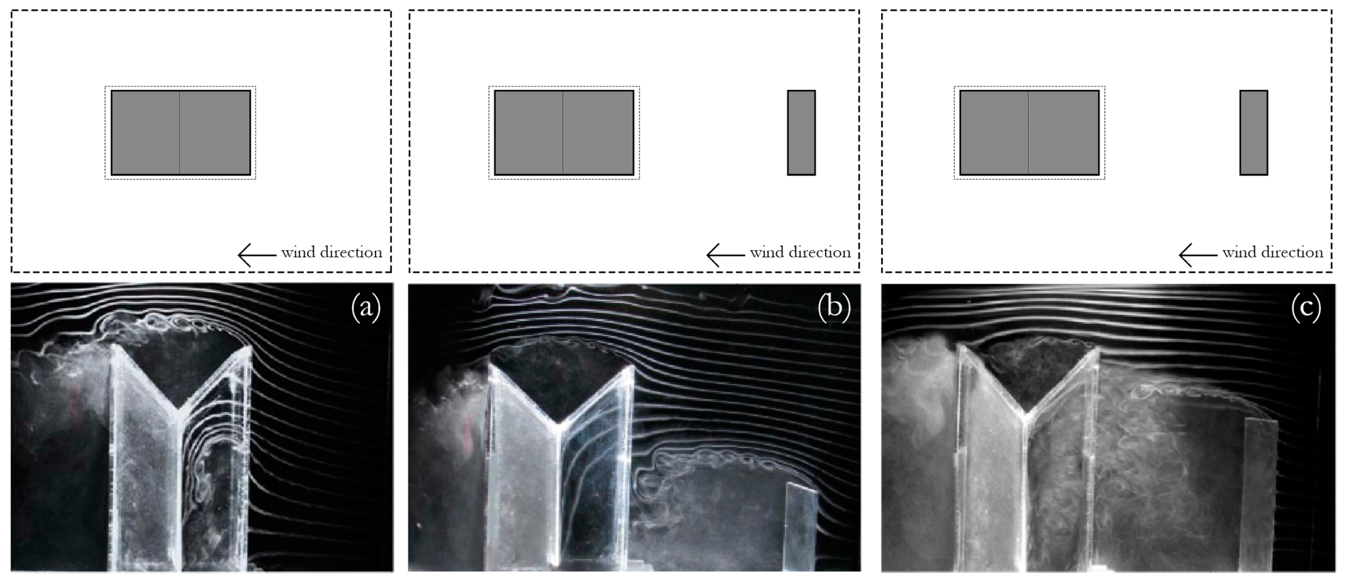
To realize the design concept, two types of windcatchers were devised: 5 m height and 10 m height. Additionally, an upstream object was incorporated to accelerate airflow toward the openings. According to refs. [44,45], 0.5 height (H) is optimal for an upstream element to enhance airflow and improve the performance of the windcatcher (Figure 9). A curved outer wall, integrated with both the upper and bottom outer wall, was designed to streamline airflow within the shaft, following recommendations from refs. [18,46,47,48,49]. Additionally, guide vanes, if necessary, will be incorporated to further optimize airflow inside the shaft, as suggested by ref. [18]. During the optimization process, the distance between the upstream object and the windcatcher (ranging from 4 to 5 m) was a variable under examination. It is important to note that the outlet size remained fixed at 1.5 m, which corresponds to the typical height of an adult human face [50].

2.3. CFD Simulation Parameters

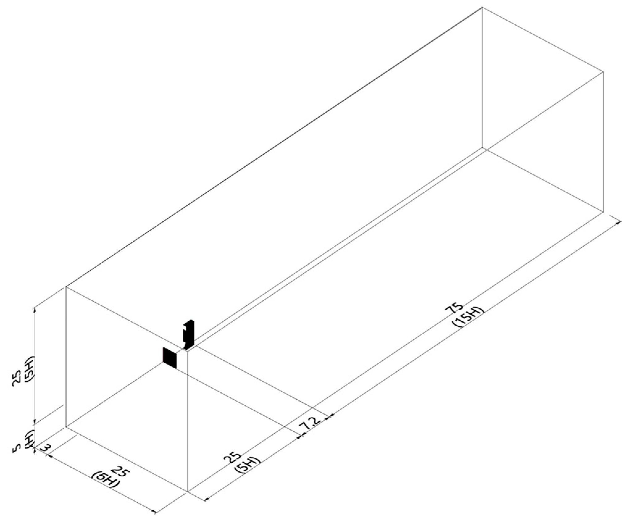
For the CFD simulation, a computational model of a reduced-scale building was constructed (details in Table 1), and the realizable k-ε turbulence model was chosen for its proven effectiveness in predicting airflow inside windcatchers, supported by previous studies [18,31,45,51]. The computational grid was fully structured, consisting of 5,561,905 tetrahedral cells for a wind incident angle of 0°. The boundary conditions were set according to the dimensions depicted in Figure 10.

3. Results

3.1. CFD Simulation

The primary objective of conducting CFD simulations was to investigate how wind is delivered and distributed at the windcatcher outlet with the designed curved shaft. Additionally, this study aimed to explore how the upstream object can support the design and accelerate wind flow inside the shaft to facilitate efficient wind delivery. To examine this, the wind velocity was set at 1.5 m/s for the 5 m high windcatcher and 4 m/s for the 10 m high windcatcher. The decision to increase the wind velocity for the 10 m high windcatcher served two purposes: firstly, to account for the higher wind flow gradient at greater heights, and secondly, to explore the functionality of the windcatcher under higher-velocity conditions. The simulation process was divided into three phases, each progressively evaluating all predetermined parameters to achieve the optimal design.
  • Phase (1): Investigating optimal opening sizes and curvature radii for the upper and bottom outer walls, while determining the ideal distance for the upstream element.
  • Phase (2): Introducing guide vanes, if necessary, to enhance airflow dynamics within the windcatcher selected in Phase (1).
  • Phase (3): Apply insights gained from Phases (1) and (2) to refine the design of the 10 m windcatcher.

3.2. Phase (1) Simulation Results

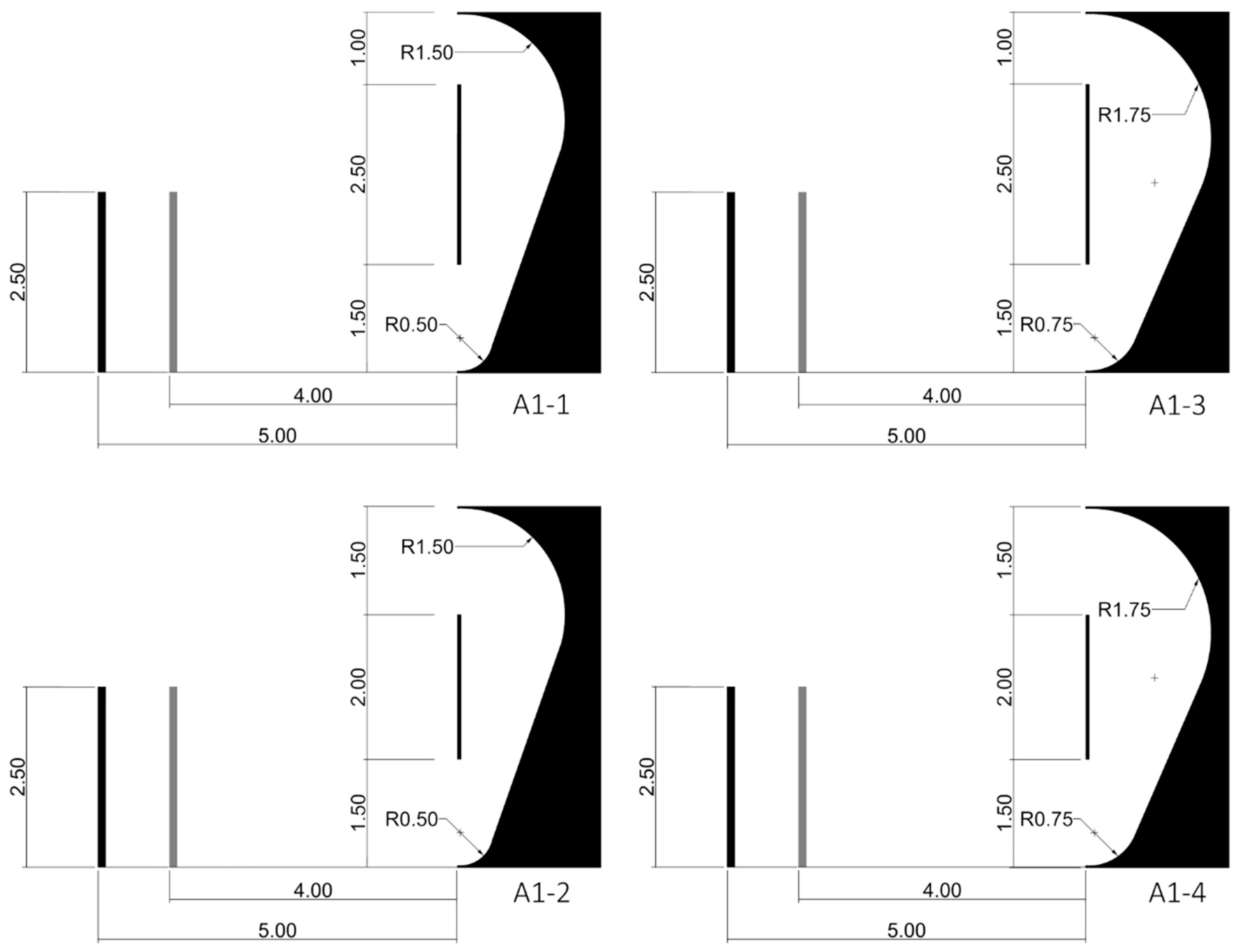
To test and optimize the designed windcatcher, a series of experiments were conducted, involving variations in windcatcher shaft geometries and distances from the upstream element. These configurations are illustrated in Figure 11 and detailed in Table A3.
The results show that incorporating both upper and bottom curved outer walls improves wind delivery at the outlet and diminishes the outer recirculation zone. Additionally, windcatchers positioned at distances of 4 and 5 m from the upstream exhibited similar performance in cases (A1-3) and (A1-4), with an exception noted for (A1-3-1). Furthermore, in the case of (A1-2-2), increasing the inlet size from 1 m to 1.5 m with a radius of 1.5 m resulted in a longer reattachment length and decreased airflow acceleration inside the shaft, as illustrated in Figure 12. Conversely, in the case of (A1-4-2), increasing the inlet size along with an increase in the radius of the outer wall to 1.75 m demonstrated enhanced airflow. However, it extended the inner recirculation zone. Ultimately, widening the inlet size and the shaft’s radius increased the inner recirculation zone and reattachment length, which need to be addressed. Based on the results, categories A1-3-2 and A1-4-2 were selected for further enhancements, as they demonstrated slight superiority over other cases, as well as offered one extra meter of space for pedestrians, leading to maximizing the use of space in the design.

3.3. Phase (2) Simulation

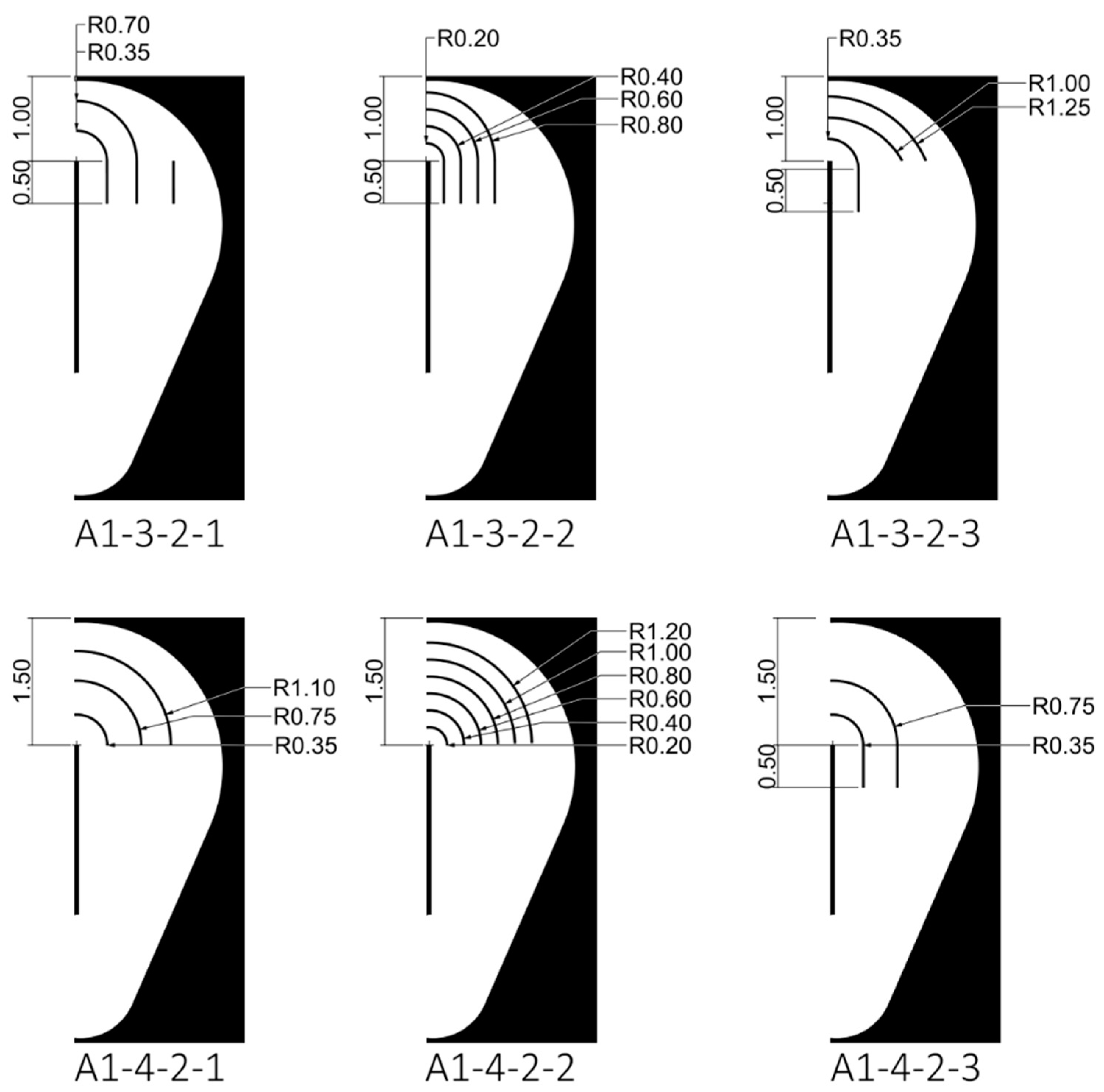
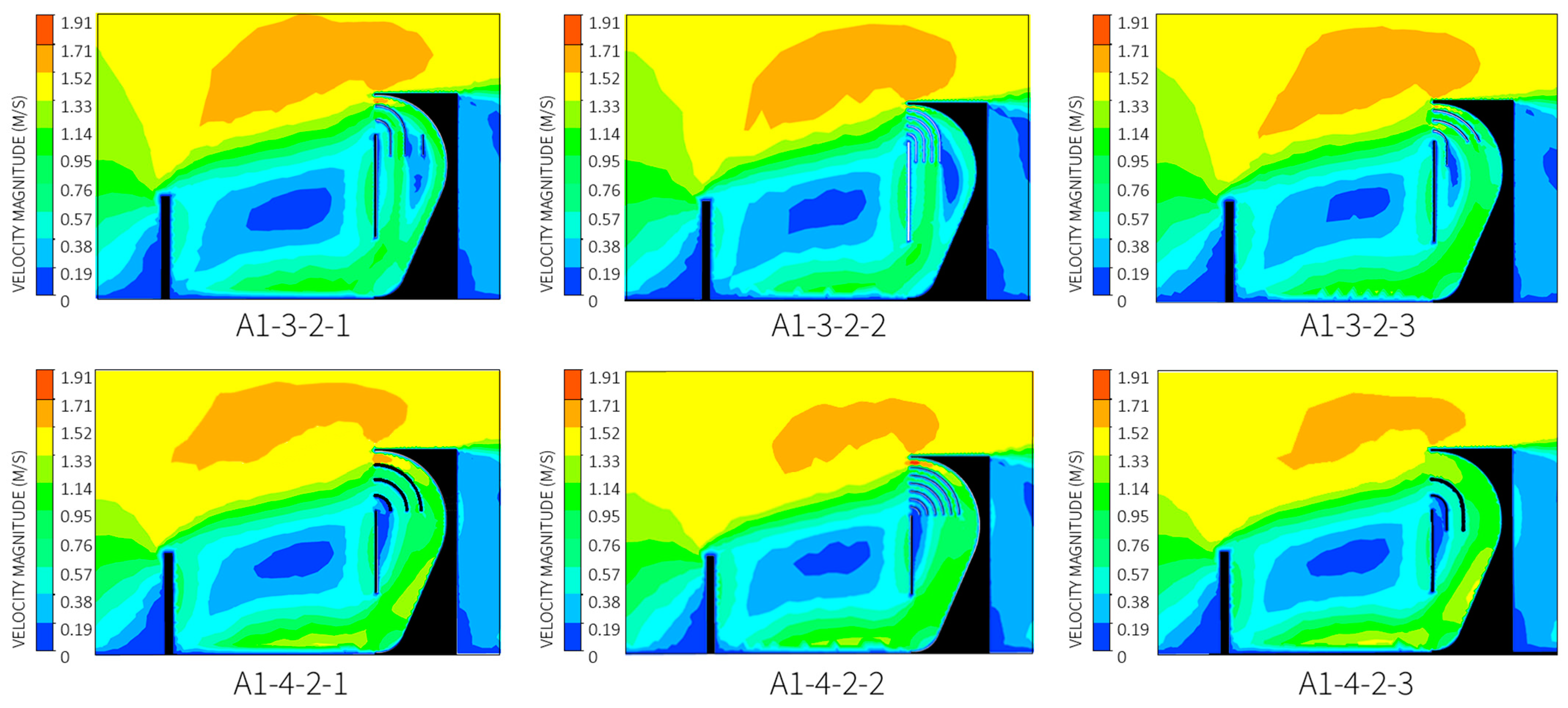
To address the issue of the inner recirculation zone, guide vanes (Figure 13 and Table A4) were introduced to assess their effectiveness in reducing reattachment length and enhancing airflow uniformity in this design, following the methodology outlined in ref. [18]. Different types of guide vanes are proposed and were designed based on the inlet size and the curvature shape of the shaft.
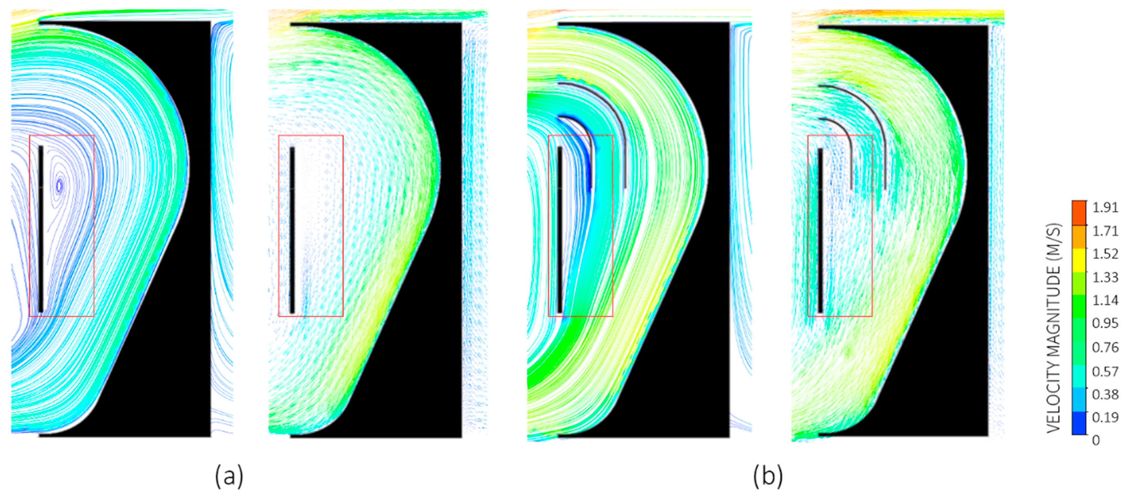
As a result, improvements are observed across all cases (Figure 14). The guide vanes prevented the outward drift of the flow in the bend and streamlined the flow by directing it through narrower channels, leading to a higher flow uniformity at the windcatcher outlet. However, while the 1 m inlet showed improved airflow and uniformity, it also exhibited a slight reduction compared to the 1.5 m inlet. This is attributed to the complexity and narrower passage of the guide vanes, which result in increased pressure losses. In contrast, with a 1.5 m inlet, the windcatcher achieved greater uniformity efficiency while maintaining accelerated airflow inside the shaft. These results underscore the critical role of attentively designing the guide vanes to optimize airflow. In the conclusion of this phase, the configuration identified as (A1-4-2-3) demonstrated slight superiority over other alternatives due to its higher uniformity, simpler design, and effective airflow acceleration and uniformity inside the shaft (Figure 15).

3.4. Phase (3) Simulation

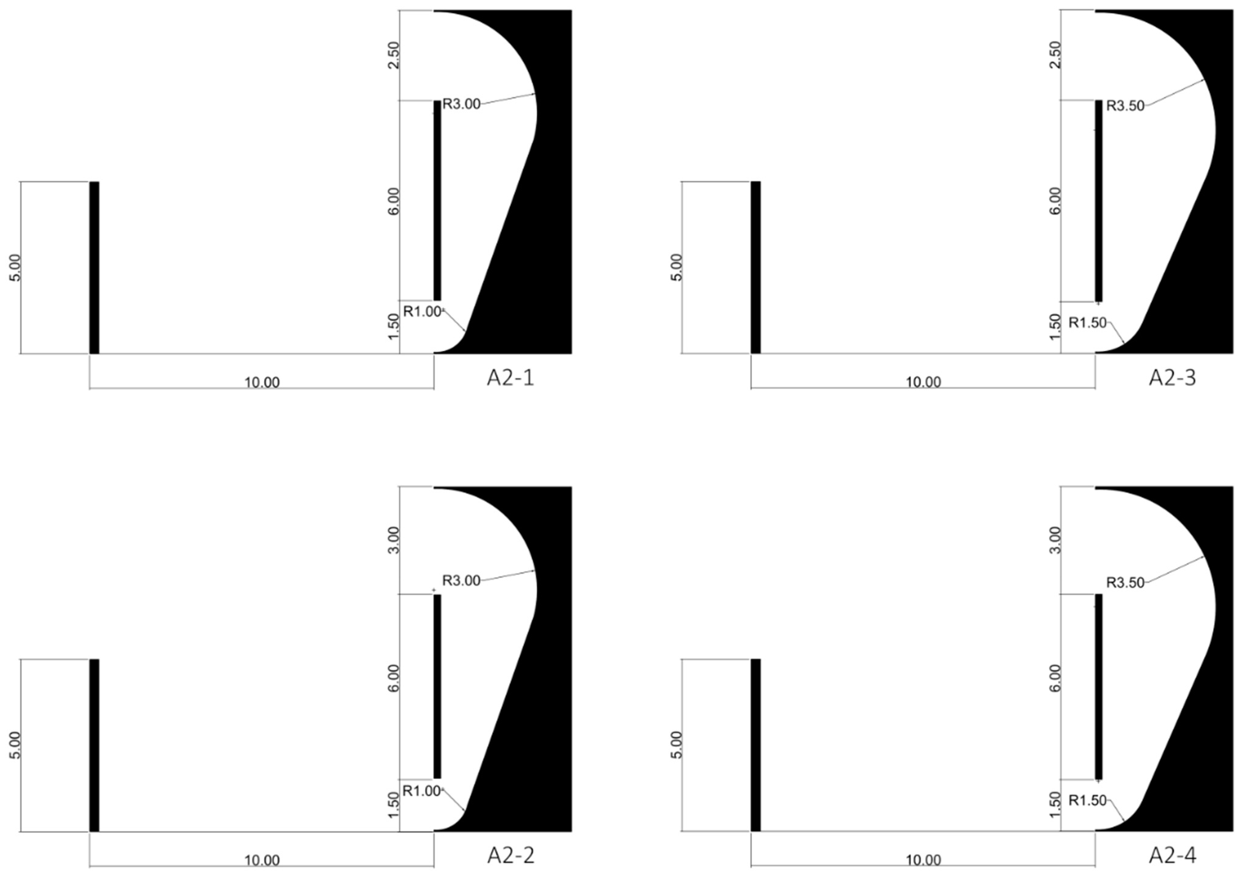
During Phase (3), simulations were conducted for a 10 m height windcatcher, characterized in Table A5 and depicted in Figure 16. The airflow across all cases was found to circulate effectively with appropriate uniformity. These configurations efficiently directed wind at an acceptable velocity (~2 m/s) and distribution, as depicted in Figure 17. However, cases A2-1 and A2-2 exhibited higher pressure levels compared to A2-3 and A2-4, attributed to narrower shaft dimensions. Increasing the radius of the outer wall was found to mitigate pressure loss, resulting in smoother airflow. Additionally, case A2-4 showed a slight advantage over A2-3, with a lower pressure observed within the shaft. These findings align well with the design requirements, indicating that the incorporation of guide vanes is not necessary.

3.5. The Designed Windcatcher in an Urban Context

The optimization study of the windcatcher design was conducted assuming an open country terrain for simplicity and to establish fundamental design concepts. However, evaluating its performance in an urban context was essential for a comprehensive understanding of its functionality. The objectives included analyzing how urban morphology and turbulence affect the windcatcher’s performance and comparing it with simulations in a free stream. This assessment aimed to offer insights into the windcatcher’s effectiveness in urban settings and suggests improvements for urban applications in the future.
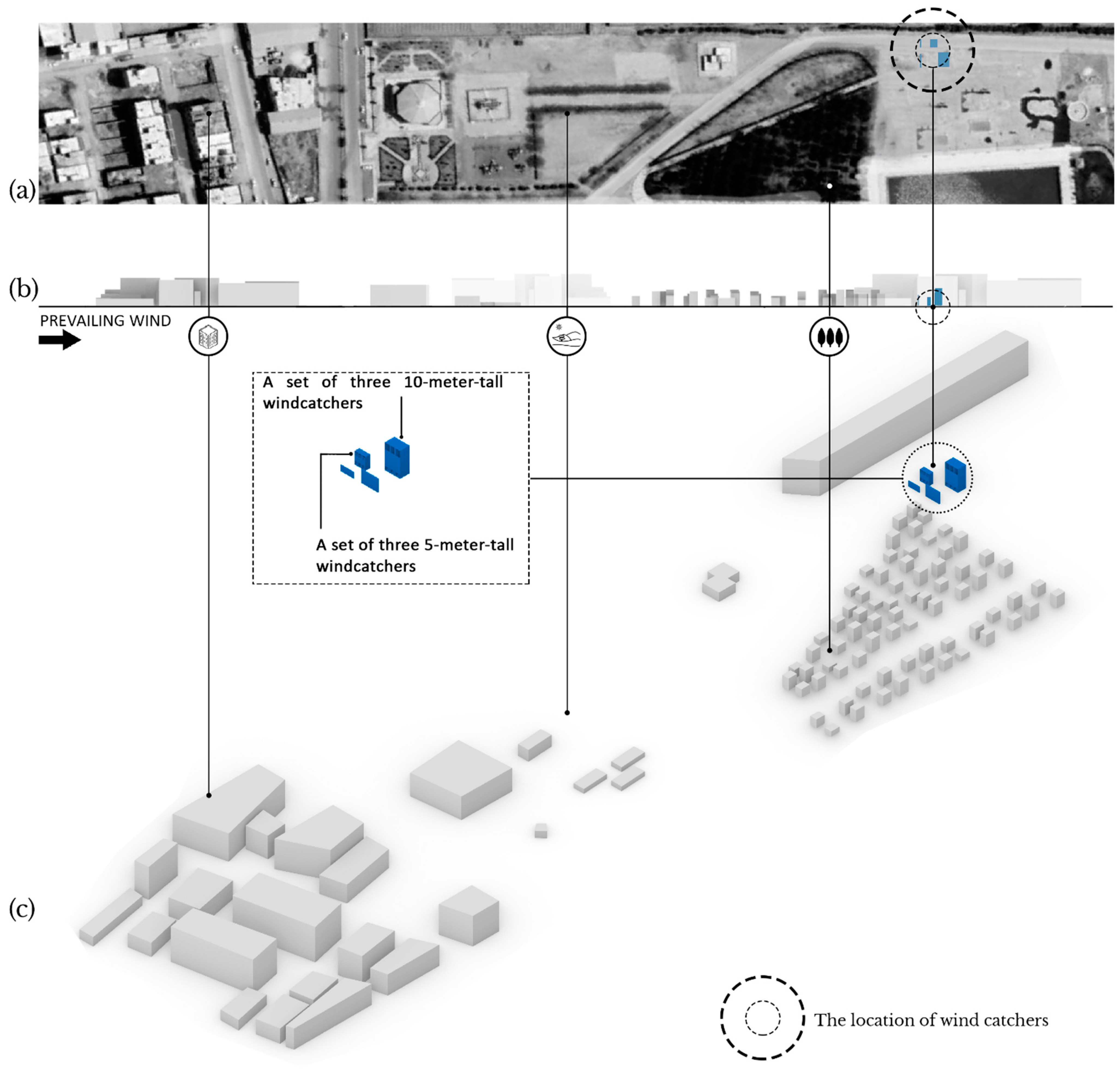
To accomplish this, we selected “Marker Park”, a location in Yazd located in the eastern part of the city (Figure A2). Yazd is known for its rich history and traditional architecture, where windcatchers have been utilized for centuries. By incorporating a new approach to the design of windcatchers, this paper contributes to preserving the cultural heritage of the region. Data extracted from Energy Plus Weather (EPW) [52], generated by Ladybug [53], indicate extreme discomfort from May to September, particularly during the daytime, with the Universal Thermal Climate Index (UTCI) peaking at around 42 °C (Figure S1a). Consequently, there is a high demand for ventilation and air conditioning systems. The prevailing wind direction, identified from the Wind Rose (Figure S1b), predominantly comes from the north–north–west (NNW) with a frequency of 12.5%. Velocities below 0.5 m/s were excluded as they are generally considered calm and may go unnoticed [54]. The wind velocity was set at 3.84 m/s at a 10 m height. For efficient simulation, the district’s 3D model (Figure 18) was simplified using 14,218,384 tetrahedral cells. Building dimensions were estimated from Google Earth Pro [55], assuming typical heights based on Eurocode terrain categories. This classification applies to areas with regular vegetation or buildings, with isolated obstacles spaced up to 20 obstacle heights apart, encompassing environments like villages, suburbs, and permanent forests [56].
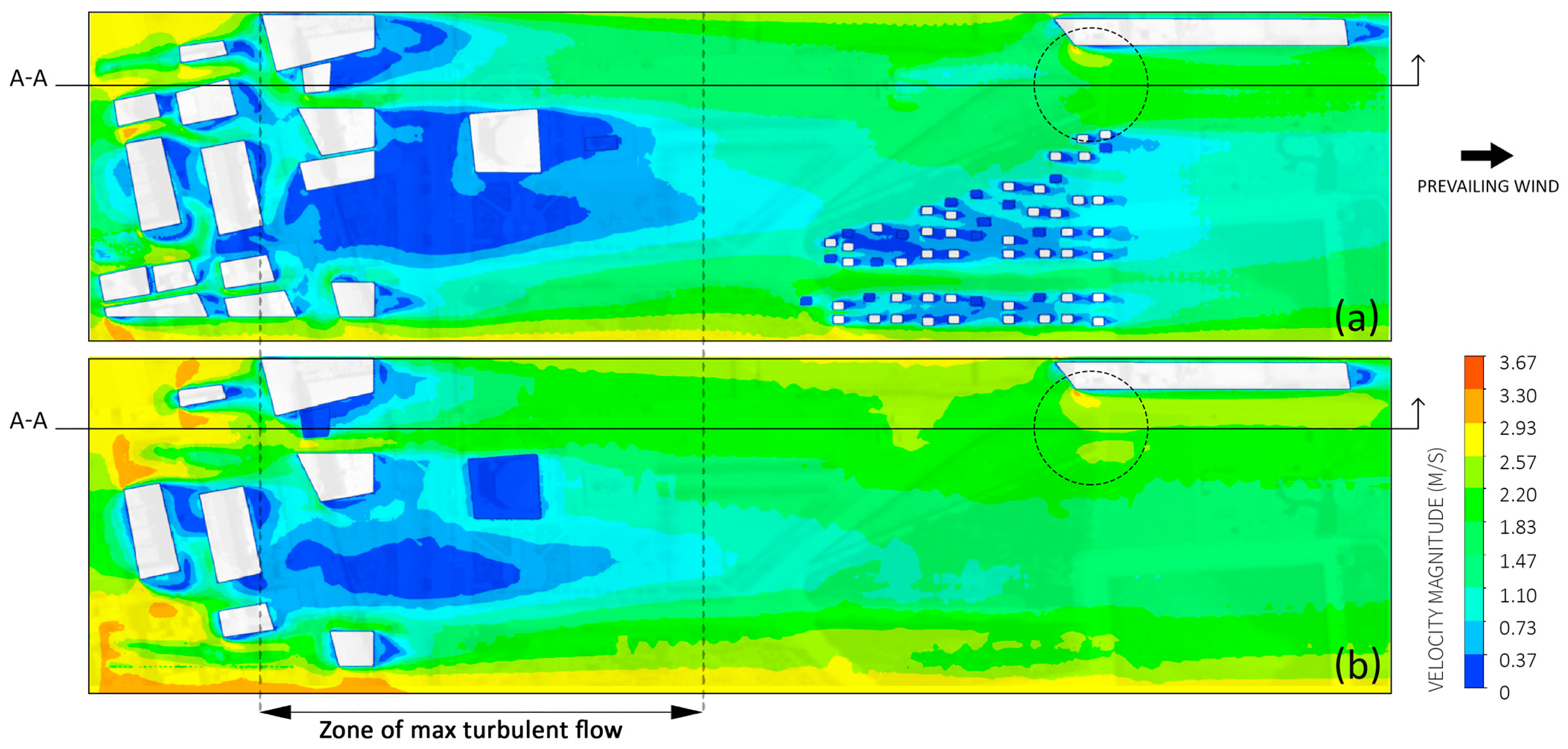
The initial step involved analyzing natural wind flow patterns in the area without windcatchers. The findings from Figure 19, marked within the dashed circle, indicate a wind-channeling effect influenced by urban morphology. This effect becomes more pronounced at higher elevations due to reduced obstruction disruptions. The presence of buildings creates an extended wake zone that directly affects airflow toward the windcatcher, leading to significant low-velocity regions caused by urban roughness. The reduction in wind velocity is primarily due to morphological factors: as the wind passes through buildings, its kinetic energy transforms into pressure energy, diminishing airflow momentum and thereby decreasing velocity.
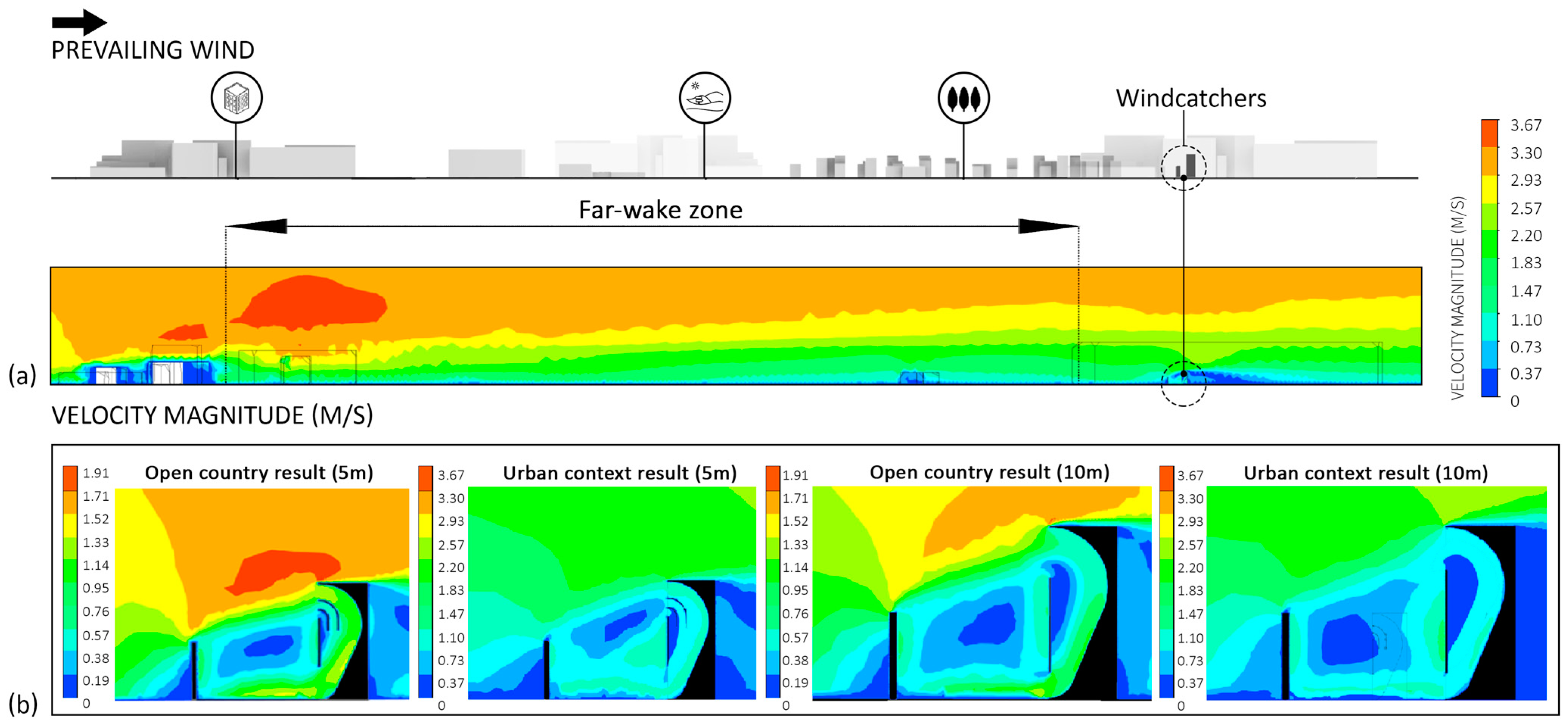
In the second step, six windcatchers were installed; three were 5 m high and the remaining three were 10 m high, as shown in Figure 18. The results indicate that reduced wind velocity diminishes the induced wind capacity of the windcatchers due to decreased airflow momentum. Additionally, upstream acceleration is less effective compared to an open country terrain. While the behavior of the designed windcatchers differs in urban contexts compared to simulations in open country settings, they still effectively deliver induced airflow within urban environments and fulfill the intended design concept. However, future improvements are necessary to enhance the design’s adaptation to urban conditions.

4. Discussion

In the simulation conducted across three phases to assess the potential of the designed windcatcher, several key observations emerged.

4.1. Open Country Simulation Result

(a)
Effectiveness of curvature in airflow: This study demonstrated that the curvature of both the upper and bottom outer walls plays a crucial role in directing airflow toward the target. By ensuring streamlined airflow, the upper curvature optimizes the air movement, while the lower curvature facilitates the delivery of the induced wind toward the outlet. These findings underscore the importance of carefully designing inner walls to maximize efficiency.
(b)
Impact of upstream on windcatcher performance: Leveraging the upstream object, in this case a wall, can be a preferred alternative to effectively channel wind toward the windcatcher’s inlet in an urban context.
(c)
Influence of inlet and curvature radius parameters on enhancing airflow and reducing pressure: In case (A1-2-2), increasing the inlet size from 1 m to 1.5 m with a 1.5 m radius results a longer reattachment length and reduced airflow acceleration. In contrast, case (A1-4-2) shows improved airflow with a larger inlet and a 1.75 m outer wall radius. This highlights the link between the inlet size and inner wall curvature. Expanding on the findings for the 10 m windcatchers, increasing the curvature radius of both the outer and inner walls led to a notable decrease in pressure within the system, facilitating improved air circulation and a more efficient distribution throughout the windcatcher. However, widening the shaft led to the formation of an inner recirculation zone, underscoring the need for careful consideration when altering structural dimensions.
(d)
Impact of guide vanes on reducing reattachment length and minimizing the inner recirculation zone: Although more complex configurations slightly impacted performance, the effectiveness of guide vanes in minimizing the inner recirculation zone was evident. These results highlight the importance of balancing design modifications to avoid negatively impacting the windcatcher’s efficiency, preferably keeping the design as simple as possible.

4.2. Urban Context Simulation Result

The initial simulations were conducted in an open country terrain setting. Recognizing the importance of understanding windcatcher performance in an urban context, a district in Yazd was selected for further testing. The goal was to evaluate the feasibility of the designed windcatcher within a dense urban fabric.
(a)
The initial step: Initial simulations without the windcatchers revealed a complex turbulent pattern and an extended wake zone due to the urban morphology. However, the selected site demonstrated a beneficial wind channel effect, making it optimal for the windcatcher installation. This finding highlights the critical importance of considering urban morphology and the impact of obstructions on general airflow conditions before implementing windcatcher designs. The simulations illustrated that existing buildings in the area accelerated wind velocity, which could be harnessed to channel airflow toward the windcatchers effectively. This acceleration is crucial for enhancing the performance of the windcatchers by increasing the airflow within the system.
(b)
The second step: Upon installing six windcatchers, it was observed that the interaction of airflow with urban structures led to a conversion of kinetic energy into pressure energy. This process resulted in a reduction in wind velocity, which in turn impacted the performance of the upstream elements and reduced acceleration due to decreased momentum (Figure 20a). Furthermore, this reduction affected the guide vanes and the overall airflow circulation within the windcatchers (Figure 20b). Despite these challenges, the simulations demonstrated that the designed windcatchers could still provide effective airflow circulation and channel higher velocity downward, even under the influence of the complex urban morphology. While turbulence and the urban fabric inevitably affect wind velocity and direction, these issues can be mitigated through future design improvements.

4.3. Research Gap

(a)
Exploration of multi-directional windcatchers: This research focused on one-sided windcatchers. Future advancements should explore the potential of multi-directional windcatchers. Integrating windcatchers with advanced technologies, such as automatic rotation toward incoming wind by utilizing sensors, could significantly enhance their performance.
(b)
Incorporation of Atmospheric Boundary-Layer (ABL) profiles: The experiments in this study primarily focused on airflow and distribution using a uniform mean wind velocity. To address this limitation, future research should incorporate ABL profiles and mean wind speed variations.
(c)
Optimization for various terrain types: The design optimization in this study was based on open country terrain without obstacles, providing a straightforward guideline and prototype. Future research should explore other terrain types to develop designs better adapted to urban conditions. This approach can raise awareness of the impact of morphological patterns on windcatcher performance and help identify the most suitable urban contexts for such designs. For instance, categorizing building morphologies could lead to guidelines for windcatcher implementation in diverse urban environments.
(d)
Evaluation of TC and OTC: The primary aim of this paper was to assess the feasibility of windcatchers as an urban feature under isothermal conditions. Future studies should evaluate the influence of windcatchers on OTC and temperature-reduction windcatchers to better understand the relationship between aerodynamic features and TC.
(e)
Impact of various upstream geometries: In the present work, the upstream object was considered a simple shape. Future research should investigate the impact of various upstream geometries on airflow and windcatcher performance to gain a deeper understanding of their external impacts such as the curved, inclined forms. This would provide more comprehensive insights into optimizing windcatcher designs based on different upstream configurations.

5. Conclusions

By identifying key research gaps, this study provides a roadmap for future advancements in windcatcher technology. The design innovatively combines traditional principles with proven strategies such as guide vanes [18], upstream objects [44,45], and curved shafts [46,47,48,49,57,58], alongside sustainable features like green façades and water elements to enhance outdoor comfort and promote sustainable urban environments. This work also encourages designers to modernize traditional designs, adapting them to meet contemporary demands. Through iterative CFD simulations, parameters such as curvature radius, inlet size, upstream height, and object placement were studied to optimize windcatcher performance. The curvature of the windcatcher walls plays a crucial role in directing airflow, while well-positioned upstream objects improve performance based on their height. Increasing the curvature radius and inlet size enhances airflow but can cause inner recirculation if dimensions are not properly balanced. Guide vanes reduce recirculation zones and reattachment lengths, with simpler designs proving more efficient. In complex urban environments, accelerated wind due to the tunnel effect can benefit windcatcher performance. However, obstructions, such as buildings or trees, can cause a reduction in wind velocity, negatively impacting upstream and vane efficiency, which highlights the need for the careful consideration of urban morphology and context. Despite these challenges, windcatchers demonstrated the potential to channel wind effectively even in the urban context if designed well. Looking ahead, future research should explore multi-directional windcatchers, incorporate ABL profiles, analyze diverse terrain types, explore the numerical and experimental analysis of TC and OTC, and investigate various upstream geometries to optimize windcatcher efficiency in urban settings.

Supplementary Materials

The following supporting information can be downloaded at: https://www.mdpi.com/article/10.3390/urbansci8040229/s1, Figure S1: Environmental data related to Yazd (the city of the case study). Figure S2: Three-dimensional visualization of the designed windcatcher.

Author Contributions

H.G.: Conceptualization, Methodology, Software, Validation, Formal analysis, Investigation, Resources, Data curation, Writing—Section (Section 1.1, Section 1.2, Section 2, Section 3, Section 4 and Section 5), Visualization; M.F.L.: Writing—introduction and abstract, Supervision, Project administration, Funding acquisition. All authors have read and agreed to the published version of the manuscript.

Funding

This research received no external funding.

Institutional Review Board Statement

Not applicable.

Informed Consent Statement

Not applicable.

Data Availability Statement

The data presented in this study are available on request from the corresponding author.

Conflicts of Interest

The authors declare that they have no known competing financial interests or personal relationships that could have appeared to influence the work reported in this paper.

Nomenclature

IEAInternational Energy Agency
HVACHeating, ventilation, and air conditioning
UHIUrban heat island
IAQIndoor air quality
OTCOutdoor thermal comfort
TCThermal comfort
QanatA system for transporting water from an aquifer or water well to the surface through an underground aqueduct; the system originated approximately 3000 years ago in Iran.
NaghbThe earth–air heat exchanger in Persian
UCLUrban canopy layer
EPWEnergy Plus Weather
UTCIUniversal Thermal Climate Index
NNWNorth–north–west
CFDComputational fluid dynamics
RWHRainwater harvesting
HHeight of windcatcher

Appendix A. Summary Tables of the Lectures

Table A1. Summary of previous lectures on internal geometrical parameters affecting windcatcher performance.
Ref.ParameterWindcatcher TypeKey Findings
[18]Roof geometry and guide vansOne-sided
-
Adding the inlet extensions, using guide vanes, and rounding the outer wall improve the performance of the windcatcher.
[46]Width, height, and curved roofFour-sided
-
Adding a curved roof can potentially increase airflow speed by promoting better aerodynamic flow over the structure.
-
Reducing the width from 2.5 m to 2 m resulted in a 34% increase in airflow through the middle, maintaining suitable comfort levels. However, further reducing the width from 2 m to 1.5 m led to a 50% increase in velocity, causing discomfort due to higher airflow speed.
[47]Shaft shape, inletOne-sided
-
Curved shapes with double inlets enhance airflow by promoting dynamic air movement, which can lead to improved airflow speeds at outlet points.
[48]Flat, inclined, and curved roofsOne-sided
-
Inclined and curved roof wind catchers achieve a 7% and 15% increase in flow rate, respectively, compared to flat roof types.
-
At air incident angles of 30° and 60° with a free stream, induced airflow is reduced by 10% and 67%, respectively.
[49]Roof geometry and the wind directionOne-sided
-
Windcatcher ventilation relies on induced pressure, which is influenced by the shape of the roof and the direction of the wind.
-
Curved roof windcatchers perform optimally at zero wind incident angles, resulting in higher induced flow rates.
[57]Flat, inclined, and curved roofsTwo-sided
-
Modifying the geometry of the inlet, such as installing a curved lip, can reduce the reduction of airspeed due to turbulence by up to 40%.
[58]Curved roofOne-sided
-
The curved roof windcatcher improved airflow distribution within the courtyard.
Table A2. Summary of previous lectures on external geometrical parameters affecting windcatcher performance.
Ref.ParameterWindcatcher TypeKey Findings
[38]Influence of terrains Two-sided
-
High roughness length and non-uniform distribution in suburban and urban terrains compared to open and rough regions with relatively smoother surface features.
-
The highest flow rate is typically observed in open terrain, primarily due to the higher average wind velocity in such environments.
-
Windcatchers demonstrated the capability to operate effectively even at lower wind velocities.
[44]Upstream Two-sided
-
The performance of a wind-catcher in high-density urban areas significantly depends on the height and distance of upstream structures relative to the windcatcher itself.
-
Implementing an upstream object with 0.5H can effectively increase the airflow directed toward the windcatcher.
[45]UpstreamOne-sided
-
A one-sided windcatcher design holds significant potential for effective ventilation in urban settings.
-
A shorter upstream configuration relative to the height of the windcatcher can enhance airflow efficiency.

Appendix B. Windcatcher Elements in Detail

Figure A1. (a) Each element comprises multiple individual features that can be tailored to suit the specific demand of the area and availability of the resources. (b) The general schematic idea to integrate a circular system, enabling the system to function effectively and sustainably. The arrows indicate the direction of water circulation. The light blue represents the pumped water entering the system, while the dark blue represents the water exiting the system for filtration and purification.
Urbansci 08 00229 g0a1

Appendix C. Summary Tables of Windcatcher Parameters in Each Phase

Table A3. Phase (1), category-A1.
CategoryA1-1A1-2A1-3A1-4
Sub-category-1, -2-1, -2-1, -2-1, -2
Size of windcatcher (m)1.5W×2L×5H1.5W×2L×5H1.5W×2L×5H1.5W×2L×5H
Height of upstream (m)2.52.52.52.5
Distance of upstream (m)4, 54, 54, 54, 5
Inlet (m)11.511.5
Upper and bottom curves (m)R1.5, R0.5R1.5, R0.5R1.75, R0.75R1.75, R0.75
Wind velocity (m/s)1.51.51.51.5
Table A4. Phase (2), category-A2.
CategoryA1-3-2A1-4-2
Sub-category-1, -2, -3-1, -2, -3
Size of windcatcher (m)1.5W×2L×5H1.5W×2L×5H
Height of upstream (m)2.52.5
Distance of upstream (m)55
Inlet (m)11.5
Upper and bottom curves (m)R1.75, R0.75R1.75, R0.75
Wind velocity (m/s)1.51.5
Table A5. Phase (3), category-A3.
CategoryA2-1A2-2A2-3A2-4
Sub-category----
Size of windcatcher (m)2W×4L×10H2W×4L×10H2W×4L×10H2W×4L×10H
Height of upstream (m)5555
Distance of upstream (m)10101010
Inlet (m)2.532.53
Upper and bottom curves (m)R3, R1R3.5, R1.5R3, R1R3.5, R1.5
Wind velocity (m/s)4444

Appendix D. Site Analysis of the Selected Area in Yazd
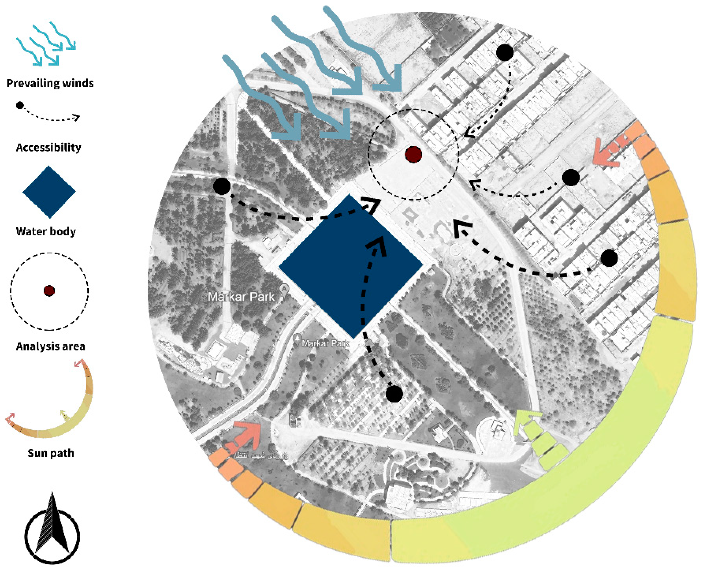
Figure A2. The site plan analysis of Makar Park, Akram Abad, Yazd, Iran (source: Google Map Pro [55]).
Urbansci 08 00229 g0a2

References

  1. IEA. CO2 Emissions in 2023; IEA: Paris, France, 2024; Available online: https://www.iea.org/reports/co2-emissions-in-2023 (accessed on 10 March 2024).
  2. Raven, J.; Stone, B.; Mills, G.; Towers, J.; Katzschner, L.; Leone, M.F.; Gaborit, P.; Georgescu, M.; Hariri, M.; Lee, J.; et al. Urban Planning and Urban Design. In Climate Change and Cities: Second Assessment Report of the Urban Climate Change Research Network; Cambridge University Press: Cambridge, UK, 2018; pp. 139–172. [Google Scholar] [CrossRef]
  3. Li, J.; Mao, Y.; Ouyang, J.; Shi, Z. A review of urban microclimate research based on CiteSpace and VOSViewer analysis. Int. J. Environ. Res. Public Health 2022, 19, 4741. [Google Scholar] [CrossRef] [PubMed]
  4. Ooka, R. Recent development of assessment tools for urban climate and heat-island investigation especially based on experiences in Japan. Int. J. Climatol. 2007, 27, 1919–1930. [Google Scholar] [CrossRef]
  5. Zhang, J.; Li, Z.; Wei, Y.; Hu, D. The impact of the building morphology on microclimate and thermal comfort-a case study in Beijing. Build. Environ. 2022, 223, 109469. [Google Scholar] [CrossRef]
  6. Kearney, M.R.; Shamakhy, A.; Tingley, R.; Karoly, D.J.; Hoffmann, A.A.; Briggs, P.R.; Porter, W.P. Microclimate modeling at macro scales: A test of a general microclimate model integrated with gridded continental-scale soil and weather data. Methods Ecol. Evol. 2014, 5, 273–286. [Google Scholar] [CrossRef]
  7. Allegrini, J.; Dorer, V.; Carmeliet, J. Influence of the urban microclimate in street canyons on the energy demand for space cooling and heating of buildings. Energy Build. 2012, 55, 823–832. [Google Scholar] [CrossRef]
  8. Pompei, L.; Nardecchia, F.; Gugliermetti, L.; Cinquepalmi, F. Design of three outdoor combined thermal comfort prediction models based on urban and environmental parameters. Energy Build. 2024, 306, 113946. [Google Scholar] [CrossRef]
  9. Nikolopoulou, M. Outdoor thermal comfort. Front. Biosci. 2011, S3, 1552. [Google Scholar] [CrossRef]
  10. Oke, T.R.; Mills, G.; Christen, A.; Voogt, J.A. Climates of Humans; Cambridge University Press: Cambridge, UK, 2017; pp. 385–407. [Google Scholar] [CrossRef]
  11. Xiao, T.; Sheng, L.; Zhang, S.; Zheng, L.; Shui, T. Thermal comfort improvement strategies for outdoor spaces in traditional villages based on ENVI-MeT: Shimengao village in Chizhou City. Sustainability 2023, 15, 11785. [Google Scholar] [CrossRef]
  12. American Society of Heating, Refrigerating and Air-Conditioning Engineers. ASHRAE Handbook: Fundamentals; American Society of Heating, Refrigerating and Air-Conditioning Engineers: Atlanta, GA, USA, 1989. [Google Scholar]
  13. Jomehzadeh, F.; Nejat, P.; Calautit, J.K.; Yusof, M.B.M.; Zaki, S.A.; Hughes, B.R.; Yazid, M.N.A.W.M. A review on windcatcher for passive cooling and natural ventilation in buildings, Part 1: Indoor air quality and thermal comfort assessment. Renew. Sustain. Energy Rev. 2017, 70, 736–756. [Google Scholar] [CrossRef]
  14. Ghaemmaghami, P.S.; Mahmoudi, M. Wind tower a natural cooling system in Iranian traditional architecture. In Proceedings of the International Conference Passive and Low Energy Cooling for the Built Environment, Santorini, Greece, 9–21 May 2005; pp. 71–76. [Google Scholar]
  15. Valipour, E.; Oshrieh, R. Survey of traditional wind catchers of the Middle East. In Proceedings of the Developing the Frontier of Sustainable Design, Engineering, and Construction 2012, Fort Worth, TX, USA, 7–9 November 2012; pp. 912–920. [Google Scholar] [CrossRef]
  16. Roaf, S. Air-conditioning avoidance: Lessons from the windcatchers of Iran. In Proceedings of the International Conference Passive and Low Energy Cooling for the Built Environment, Santorini, Greece, 9–21 May 2005; pp. 1053–1057. [Google Scholar]
  17. Ji, Z.; Su, Y.; Khan, N. Performance evaluation and energy saving potential of windcatcher natural ventilation systems in China. Int. J. Arch. Eng. Constr. 2012, 1, 84–95. [Google Scholar] [CrossRef]
  18. Alsailani, M.; Montazeri, H.; Rezaeiha, A. Towards optimal aerodynamic design of wind catchers: Impact of geometrical characteristics. Renew. Energy 2021, 168, 1344–1363. [Google Scholar] [CrossRef]
  19. Jomehzadeh, F.; Hussen, H.M.; Calautit, J.K.; Nejat, P.; Ferwati, M.S. Natural ventilation by windcatcher (Badgir): A review on the impacts of geometry, microclimate and macroclimate. Energy Build. 2020, 226, 110396. [Google Scholar] [CrossRef]
  20. Haghighi, A.; Pakdel, S.H.; Jafari, A. A study of a windcatcher assisted adsorption cooling channel for natural cooling of a 2-storey building. Energy 2016, 102, 118–138. [Google Scholar] [CrossRef]
  21. Saadatian, O.; Haw, L.C.; Sopian, K.; Sulaiman, M.A. Review of windcatcher technologies. Renew. Sustain. Energy Rev. 2012, 16, 1477–1495. [Google Scholar] [CrossRef]
  22. Jafarian, M.; Jaafarian, S.M.; Haseli, P.; Mohebbi, A. Performance analysis of a passive cooling system using underground channel (Naghb). Energy Build. 2010, 42, 559–562. [Google Scholar] [CrossRef]
  23. Erell, E.; Pearlmutter, D.; Etzion, Y. A multi-stage down-draft evaporative cool tower for semi-enclosed spaces: Aerodynamic performance. Sol. Energy 2008, 82, 420–429. [Google Scholar] [CrossRef]
  24. Li, L.; Mak, C.M. The assessment of the performance of a windcatcher system using computational fluid dynamics. Build. Environ. 2007, 42, 1135–1141. [Google Scholar] [CrossRef]
  25. Reyes, V.; Sierra, F.; Moya, S.L.; Carrillo, F. Flow field obtained by PIV technique for a scaled building-wind tower model in a wind tunnel. Energy Build. 2015, 107, 424–433. [Google Scholar] [CrossRef]
  26. Shorbagy, A.M.E. Design with Nature: Windcatcher as a Paradigm of Natural Ventilation Device in Buildings. Int. J. Civ. Environ. Eng. IJCEE IJENS 2012, 10, 21–26. [Google Scholar]
  27. Hassan, A.M.; Lee, H.; Yoo, U.-S. From medieval Cairo to modern Masdar City: Lessons learned through a comparative study. Archit. Sci. Rev. 2015, 59, 39–52. [Google Scholar] [CrossRef]
  28. Ecosistema Urbano. Available online: https://ecosistemaurbano.com/eco-boulevard/ (accessed on 1 July 2024).
  29. Soutullo, S.; Olmedo, R.P.; Sánchez, M.N.; Heras, M.R. Thermal conditioning for urban outdoor spaces through the use of evaporative wind towers. Build. Environ. 2011, 46, 2520–2528. [Google Scholar] [CrossRef]
  30. Soutullo, S.; Guaita, C.S.; Sánchez, M.N.; Zarzalejo, L.F.; Miranda, R.E.; Del Rosario Heras Celemín, M. Comfort evaluation in an urban boulevard by means of evaporative wind towers. Energy Procedia 2012, 30, 1226–1232. [Google Scholar] [CrossRef]
  31. Montazeri, H.; Montazeri, F. CFD simulation of cross-ventilation in buildings using rooftop wind-catchers: Impact of outlet openings. Renew. Energy 2018, 118, 502–520. [Google Scholar] [CrossRef]
  32. Zaki, A.; Richards, P.J.; Sharma, R.N. Analysis of airflow inside a two-sided wind catcher building. J. Wind. Eng. Ind. Aerodyn. 2019, 190, 71–82. [Google Scholar] [CrossRef]
  33. Rup, K.; Sarna, P. Analysis of turbulent flow through a square-sectioned duct with installed 90-degree elbow. Flow Meas. Instrum. 2011, 22, 383–391. [Google Scholar] [CrossRef]
  34. Chew, L.W.; Nazarian, N.; Norford, L.K. Pedestrian-Level Urban Wind Flow Enhancement with Wind Catchers. Atmosphere 2017, 8, 159. [Google Scholar] [CrossRef]
  35. Palusci, O.; Cecere, C. Urban Ventilation in the Compact City: A Critical review and a Multidisciplinary Methodology for improving Sustainability and Resilience in Urban areas. Sustainability 2022, 14, 3948. [Google Scholar] [CrossRef]
  36. Oke, T.R. The distinction between canopy and boundary-layer urban heat islands. Atmosphere 1976, 14, 268–277. [Google Scholar] [CrossRef]
  37. Blocken, B.B.; Carmeliet, J.J. Pedestrian Wind Environment around Buildings: Literature Review and Practical Examples. J. Therm. Envel. Build. Sci. 2004, 28, 107–159. [Google Scholar] [CrossRef]
  38. Nejat, P.; Calautit, J.K.; Fekri, Y.; Sheikhshahrokhdehkordi, M.; Alsaad, H.; Voelker, C. Influence of terrain and atmospheric boundary layer on the ventilation and thermal comfort performance of windcatchers. J. Build. Eng. 2023, 73, 106791. [Google Scholar] [CrossRef]
  39. Nikolopoulou, M.; Lykoudis, S. Use of outdoor spaces and microclimate in a Mediterranean urban area. Build. Environ. 2007, 42, 3691–3707. [Google Scholar] [CrossRef]
  40. National Weather Service. Available online: https://www.weather.gov/ddc/windchillddc#:~:text=Wind%20Chill%20Calculator&text=Wind%20chill%20temperature%20is%20a,temperature%20(which%20can%20kill) (accessed on 1 June 2024).
  41. Givoni, B. Indoor temperature reduction by passive cooling systems. Sol. Energy 2011, 85, 1692–1726. [Google Scholar] [CrossRef]
  42. Roghanchi, P.; Kocsis, K.C.; Sunkpal, M. Sensitivity analysis of the effect of airflow velocity on the thermal comfort in underground mines. J. Sustain. Min. 2016, 15, 175–180. [Google Scholar] [CrossRef]
  43. Mostafaeipour, A.; Bardel, B.; Mohammadi, K.; Sedaghat, A.; Dinpashoh, Y. Economic evaluation for cooling and ventilation of medicine storage warehouses utilizing wind catchers. Renew. Sustain. Energy Rev. 2014, 38, 12–19. [Google Scholar] [CrossRef]
  44. Afshin, M.; Sohankar, A.; Manshadi, M.D.; Daneshgar, M.R.; Kamaragi, G.R.D. Visualized Flow Patterns around and inside a Two-Sided Wind-Catcher in the Presence of Upstream Structures. Int. J. Energy Power Eng. 2014, 8, 1312–1317. [Google Scholar] [CrossRef]
  45. Montazeri, H.; Azizian, R. Experimental study on natural ventilation performance of one-sided wind catcher. Build. Environ. 2008, 43, 2193–2202. [Google Scholar] [CrossRef]
  46. Hosseini, S.H.; Shokry, E.; Hosseini, A.J.A.; Ahmadi, G.; Calautit, J.K. Evaluation of airflow and thermal comfort in buildings ventilated with wind catchers: Simulation of conditions in Yazd City, Iran. Energy Sustain. Dev. 2016, 35, 7–24. [Google Scholar] [CrossRef]
  47. Alwetaishi, M.; Gadi, M.B. New and innovative wind catcher designs to improve indoor air quality in buildings. Energy Built Environ. 2021, 2, 337–344. [Google Scholar] [CrossRef]
  48. Esfeh, M.K.; Dehghan, A.A.; Manshadi, M.D.; Mohagheghian, S. Visualized flow structure around and inside of one-sided wind-catchers. Energy Build. 2012, 55, 545–552. [Google Scholar] [CrossRef]
  49. Dehghan, A.A.; Esfeh, M.K.; Manshadi, M.D. Natural ventilation characteristics of one-sided wind catchers: Experimental and analytical evaluation. Energy Build. 2013, 61, 366–377. [Google Scholar] [CrossRef]
  50. National Weather Service. Available online: https://www.weather.gov/safety/cold-wind-chill-chart (accessed on 1 June 2024).
  51. Shih, T.; Liou, W.W.; Shabbir, A.; Yang, Z.; Zhu, J. A New K-Epsilon Eddy Viscosity Model for High Reynolds Number Turbulent Flows: Model Development and Validation; NASA Technical Report Server: Washington, DC, USA, 1994; Volume 95, p. 11442.
  52. Roudsari, M.S.; Pak, M.; Viola, A. Ladybug: A parametric environmental plugin for Grasshopper to help designers create an environmentally-conscious design. In Proceedings of the Building Simulation 2013: 13th Conference of IBPSA, Chambery, France, 26–28 August 2013; pp. 3128–3135. [Google Scholar] [CrossRef]
  53. Energy Plus. Available online: https://energyplus.net/ (accessed on 28 May 2024).
  54. National Weather Service. Available online: https://www.weather.gov/pqr/wind (accessed on 28 May 2024).
  55. Google Earth Pro, Yazd, Iran. Available online: https://www.google.com/maps/place/31%C2%B052’43.0%22N+54%C2%B023’54.0%22E/@31.8785898,54.3969853,565m/data=!3m1!1e3!4m4!3m3!8m2!3d31.8786111!4d54.3983333?entry=ttu&g_ep=EgoyMDI0MTEyNC4xIKXMDSoASAFQAw%3D%3D(31°52’43”N 54°23’54”E) (accessed on 26 November 2024).
  56. Eurocode Tools. Available online: https://eurocodes-tools.com/en/roughness-factor-crz (accessed on 15 February 2024).
  57. Pearlmutter, D.; Erell, E.; Etzion, Y.; Meir, I.A.; Di, H. Refining the use of evaporation in an experimental down-draft cool tower. Energy Build. 1996, 23, 191–197. [Google Scholar] [CrossRef]
  58. Benkari, N.; Fazil, I.; Husain, A. Design and performance comparison of two patterns of wind-catcher for a semi-enclosed courtyard. Int. J. Mech. Eng. Robot. Res. 2017, 6, 396–400. [Google Scholar] [CrossRef]
Figure 1. Urban climate factors (credit: Jeffrey Raven, 2016) [2].
Urbansci 08 00229 g001
Figure 2. (a) Evaporative cooling system; (b) air path through the Badgir and earth (credit: Hossein Ghandi, 2024).
Urbansci 08 00229 g002
Figure 3. Air Tree, Eco-boulevard in Vallecas, Madrid. “Used with permission from Ecosistema Urbano as designer and Emilio P. Doiztua as photographer; published by Ecosistema Urbano [28]”.
Urbansci 08 00229 g003
Figure 4. (a) Flow topology inside a one-sided windcatcher (vertical cross section) and (b) pressure distribution across a diagonal plane in the bend (© 2020 Alsailani et al., Published by Elsevier Ltd.) [18].
Urbansci 08 00229 g004
Figure 5. On a summer day in the Friedrichsplatz garden in Mannheim, Germany, visitors sought relief by sitting in the shade of the trees or cooling off in the water pool (credit: Hossein Ghandi, 2024).
Urbansci 08 00229 g005
Figure 6. Preliminary conceptual sketches during the initial design steps.
Urbansci 08 00229 g006
Figure 7. Adaptability of the design to site restrictions.
Urbansci 08 00229 g007
Figure 8. Designed with adaptability and functionality for different seasons: (a) during summer, the system demonstrates its functionality by adjusting to the specific needs of the area. For instance, in humid climates, using water features may not be desirable and can easily be replaced with a green wall to maintain effectiveness. (b) In winter, the inlets are closed to prevent wind circulation, allowing the structure to serve as a shelter for pedestrians.
Urbansci 08 00229 g008
Figure 9. Flow visualization with smoke (a) for an isolated windcatcher model, (b) placing under the short upstream object H/2, and (c) with longer a H/3 (H is the height of the windcatcher); “used with permission from Afshin et al. [44], “Visualized Flow Patterns around and inside a Two-Sided Wind-Catcher in the Presence of Upstream Structures”, published by the World Academy of Science, Engineering, and Technology, 2014 (crop from the original)”.
Urbansci 08 00229 g009
Figure 10. Computational domain adapted to the model [18].
Urbansci 08 00229 g010
Figure 11. Simulation parameters for Phase (1).
Urbansci 08 00229 g011
Figure 12. The CFD simulation results from Phase (1).
Urbansci 08 00229 g012
Figure 13. Guide vanes’ configurations for Phase (2).
Urbansci 08 00229 g013
Figure 14. The CFD simulation results from Phase (2).
Urbansci 08 00229 g014
Figure 15. (a) The airflow inside a shaft without guide vanes, as illustrated by red box, exhibits a long recirculation length. (b) The enhancement of guide vanes improves airflow, as highlighted within the red box.
Urbansci 08 00229 g015
Figure 16. Simulation parameters for Phase (3).
Urbansci 08 00229 g016
Figure 17. The CFD simulation results from Phase (3).
Urbansci 08 00229 g017
Figure 18. (a) The boundary of the simulation model (source: Google Earth Pro [55]). (b) Section from the 3D model. (c) The simplified 3D model used for simulation.
Urbansci 08 00229 g018
Figure 19. (a) The site plans of the area with a section taken 5 m above ground level and (b) the section at 10 m above ground level to highlight the differences in wind patterns in the area.
Urbansci 08 00229 g019
Figure 20. (a) Section A-A (check Figure 19). (b) Comparison of the CFD simulation in the urban context and open country boundary.
Urbansci 08 00229 g020
Table 1. Summary of the CFD model boundary conditions [18].
Near-wall treatmentStandard wall functions
Turbulence modelRealizable k-ε
DiscretizationSecond-order
Pressure interpolationSecond-order
Pressure–velocity couplingSimple
Pressure outletStatic, gage, value = 0
Disclaimer/Publisher’s Note: The statements, opinions and data contained in all publications are solely those of the individual author(s) and contributor(s) and not of MDPI and/or the editor(s). MDPI and/or the editor(s) disclaim responsibility for any injury to people or property resulting from any ideas, methods, instructions or products referred to in the content.