Article

Multifractal Characteristics of Smooth Blasting Overbreak in Extra-Long Hard Rock Tunnel

1
School of Resources and Safety Engineering, Central South University, Changsha 410083, China
2
College of Water Resources and Civil Engineering, Hunan Agricultural University, Changsha 410128, China
3
Road & Bridge North China Engineering Co., Ltd., Beijing 101100, China
*
Authors to whom correspondence should be addressed.
Fractal Fract. 2023, 7(12), 842; https://doi.org/10.3390/fractalfract7120842
Submission received: 24 October 2023 / Revised: 21 November 2023 / Accepted: 21 November 2023 / Published: 27 November 2023
(This article belongs to the Special Issue Fractal and Fractional in Geotechnical Engineering)

Abstract

:
With the development of infrastructure construction in mountainous areas, the number of new extra-long tunnels is increasing. However, these tunnels often face the challenge of complex and variable surrounding rock grades, resulting in a large number of overbreak and underbreak due to the untimely adjustment of smooth blasting parameters. This study focuses on the optimization of the peripheral hole charging structure and blasting parameters for extra-long hard rock tunnels, aiming to improve the effectiveness of smooth blasting technology. The results of this study demonstrate a significant improvement in the effect of smooth blasting after implementing bidirectional polymerization blasting in the tunnel. A comparison between the bidirectional shaped charge and spaced decoupled charge blasting reveals that the former yields better results. To obtain accurate data on the tunnel section profile during excavation, a laser cross-section meter is used for measurement. Furthermore, this study quantitatively compares the optimization effect of smooth blasting parameters. The multifractal characteristics of the tunnel profile overbreak point sequences are analyzed under different smooth blasting schemes using the multifractal detrended fluctuation analysis (MF-DFA) method. It is found that both the spaced decoupled charge and the bidirectional shaped charge blasting exhibit multifractal features in the overbreak measurement point sequences. The calculation results of the multifractal features of the tunnel profile under different smooth blasting plans are in line with the actual situation.

1. Introduction

With the rapid development of economic globalization, the scale and quantity of railroad tunnel construction in China have significantly increased. China has the largest number of tunnels, the fastest development speed, and the most complex geological and structural forms in the world [1]. By the end of 2022, the total mileage of China’s railroads reached 155,000 km, with over 42,000 km of high-speed railroads in operation. Among them, 4178 high-speed railroad tunnels, totaling 7032 km, have been constructed, including 105 tunnels longer than 10 km, with a total length of approximately 1339 km. In recent years, the construction of extra-long railroad tunnels in China has rapidly advanced. With the gradual expansion of the construction scale of railroad tunnels, tunnel construction technology is also in constant development [2].
In the process of constructing extra-long tunnels, excavation is the most critical and time-consuming process, which significantly impacts the construction period. Long tunnels have limited working faces, large project volumes, complex hydrogeological conditions, and numerous uncontrollable factors [3,4]. As a result, the construction period of extra-long tunnels is typically the determining factor for the overall project. With the development of infrastructure construction in mountainous areas, the number of new extra-long tunnels is on the rise. This increase in tunnel construction complexity, longer construction periods, and higher construction risks pose challenges for dealing with complex geological conditions [5]. Blasting is the first and most crucial process in tunnel excavation, and subsequent processes such as mucking and support are based on successful blasting operations [6]. The effectiveness of blasting has a significant impact on project progress, quality, and cost [7], particularly in long hard rock tunnels where smooth blasting plays a critical role in maintaining the construction schedule [8,9]. Therefore, how to ensure the effects of smooth blasting in extra-long tunnels will be a difficult problem in tunnel construction.
The effectiveness of smooth blasting in extra-long tunnels is influenced by various complex factors. In addition to the blasting parameters (perimeter hole spacing, charge, decoupling coefficient, and minimum burden), the surrounding rock conditions (degree of fissure development, rock properties, and rock strength) and drilling accuracy also play important roles [10,11,12,13]. Therefore, in tunnels with complex geological conditions and variable surrounding rock grades, the untimely adjustment of blasting parameters often leads to a large number of overbreak and underbreak, resulting in project delays [7,14,15,16,17]. Relevant project data indicate that the time spent on dealing with construction quality issues such as overbreak accounts for 30% of the total construction period of the tunnel [18]. Overbreak not only increases the amount of concrete required for the initial support or even the secondary lining, but also affects the safety of the tunnel cavity [19]. Addressing underbreak is also a critical aspect of tunnel construction. If underbreak is treated using drill and blast methods, it can be time-consuming, and dynamite blasting to address undercutting may lead to overbreak.
It is well-known that new blasting methods such as supercritical carbon dioxide, soundless chemical demolition agents, and high-pressure gas expansion have the advantages of safety and environmental protection [20,21]. These new blasting methods can effectively control the overbreak and underbreak problems of tunnel blasting. However, due to the high cost of new blasting, it cannot be widely used in extra-long hard rock tunnels. Traditional blasting is widely used in extra-long tunnels due to its mature technology and economic benefits. Currently, the optimization of blasting parameters and improvement of blasting equipment are the main focus in the research of extra-long hard rock tunnel blasting technology [10,22]. The efficiency of blasting construction is a crucial factor that determines the progress of the entire project. To optimize the drilling and blasting technology for rapid tunnel boring in hard rock tunnels, scholars have conducted research on explosive selection, drilling accuracy, trenching program, blasting footage, detonation network, and other aspects [3,10,23]. Through the improvement of blasting parameters and blasting equipment, the efficiency of extra-long hard rock tunnel boring projects has significantly improved. Some scholars have optimized the blasting parameters using evaluation and prediction models [24,25,26,27]. For instance, Jang et al. [28] predicted the distribution of the fragmentation size of the debris after blasting using a neural network model, obtained the relationship between the rock fragmentation size and blasting parameters, and optimized the blasting parameters accordingly. Ma et al. [29] conducted a series of bursting tests in the tunnel excavation face to improve the construction efficiency of large section tunnels and reduce production costs. They determined the critical distance of emulsified explosives under the bursting hole constraint and proposed the bare surface blasting technology without a detonating cord. Pan et al. [30] determined the peripheral hole parameters by an eccentric charging structure and studied the blasting effect of different charging structures based on the Riedel–Hiermaier–Thoma (RHT) model. They concluded that the eccentric charging structure has an obvious eccentric pressure and optimized the parameters of surface blasting to control the phenomenon of under-excavation. Numerous scholars at home and abroad have conducted extensive research on the quality control of tunnel smooth blasting, which mainly involves repeated tests and the optimization of blasting parameters [22,31], computer simulation [32,33,34,35,36], three-dimensional laser scanning [37,38], and other techniques [39,40], thus proposing reasonable control techniques.
Multifractals were introduced by Grassberger in the 1980s [41]. The multifractal theory uses geometric probability to describe the local singularities of measures and functions. It utilizes generalized information dimensions and multifractal spectra to describe fractal objects and is an important development in fractal theory [42,43]. Compared with single fractal methods, multifractal methods describe the fractal structure through spectral functions, which can more finely characterize the volatility of fractal objects at different levels [44]. In recent years, some researchers have applied multifractals to the field of geotechnical engineering [45,46,47]. There are a large number of studies in the characterization of structural surface features of rock bodies and the characterization of rock acoustic emission signals [48,49,50]. In the field of tunnel blasting, Yin et al. [51] calculated the fractal dimension of tunnel blasting contour lines. The indicator levels and weights were obtained by cluster analysis and the combined assignment method. An unconfirmed metric model was established and applied to the tunnel blasting evaluation. Li et al. [52] carried out explosion tests on granite specimens under different stress states and analyzed the morphology and fractal characteristics of radial fracturing on the rock surface after blasting. In addition, a large number of scholars have studied the multifractal characteristics of undesirable geological bodies such as rock bursts, faults, and karsts that may exist in tunnel construction [53,54,55]. Therefore, the multifractal theory can be used to analyze the characteristics of overbreak and underbreak of tunnel blasting contour lines and evaluate the construction effect of tunnel smooth blasting.
In previous studies on the drilling and blasting method for extra-long tunnels, the focus has primarily been on optimizing the blasting parameters and improving the drilling accuracy. The objective of this approach is to reduce the problem of overbreak and underbreak during tunnel excavation and enhance the effectiveness of smooth blasting. However, for long tunnels with complex and variable surrounding rock grades, the untimely adjustment of blasting parameters often results in significant overbreak and underbreak issues. To address this challenge, this study employs a combination of theoretical analysis, field tests, and multifractal analysis to conduct an in-depth investigation into the technology of smooth blasting in extra-long hard rock tunnels. The main areas of research encompass the following aspects: (1) Optimizing the peripheral hole charging structure and blasting parameters to enhance the effectiveness of smooth blasting in tunnels. (2) Measuring the actual excavation contour line of the tunnel section using a laser section meter. This enables the acquisition of specific data on the overbreak and underbreak of the tunnel profile line, facilitating a quantitative comparison of the optimization effect of smooth blasting parameters. (3) Utilizing the multifractal detrending fluctuation analysis method to analyze the multifractal characteristics of the sequence of measurement points for overbreak and underbreak in the tunnel profile under different smooth blasting schemes. The calculated results are subsequently compared with the actual situation.

2. Materials and Methods

2.1. Overview of the Tunnel Project

2.1.1. Tunnel Project Introduction

A high-speed railway tunnel, classified as an extra-long tunnel, spans a total length of 10.8 km. The tunnel’s inlet mileage is DK102+727.765, while the exit mileage is DK113+573.89, resulting in a total length of 10,846.125 m. The elevation of the inlet track stands at 460.2 m, whereas the exit track’s elevation is 264.0302 m. Positioned within the middle mountainous region of the tectonic structure, the tunnel traverses the mountain range, characterized by significant terrain undulations. The mountain’s elevation ranges from 250 m to 885 m, with a maximum difference of approximately 635 m. The mountain slopes are steep, with a natural gradient of 40° to 55°, and local areas reaching a steepness of around 500 m. The tunnel itself reaches a maximum depth of approximately 500 m. The surface vegetation along the tunnel route is dense, primarily consisting of tall trees with weeds and shrubs interspersed. The tunnel project roadmap and layout plan can be observed in Figure 1.
The tunnel incorporates two transverse holes, with this study focusing on the section between tunnel DK107+530 and exit DK113+574. The cross-hole is positioned on the right side of the line’s forward direction and intersects with the main tunnel at DK110+850. The angle between the cross-hole and the line mileage direction is 60°, and the overall slope is 1.3%. The cross-hole’s mileage is PKHDK0+945, 0utilizing double lanes for trackless transportation, with a length of 945 m.
The mountain structure of the tunnel area predominantly consists of a backward sloping structure from north to south, primarily exhibiting monoclinic terrain. The slopes on both sides of the tunnel are steeper. The rock formation at the tunnel entrance is relatively fragmented, posing risks of dangerous rocks and rockfall incidents. The surrounding rocks of the mountain consist mainly of metasedimentary siltstone, sandstone, kyanite siltstone, and Aurignacian siltstone. The tunnel site area contains a fracture zone and several joints. Three types of parent materials were selected and sent to the Testing Center of Geological Engineering Survey Institute for rock and mineral identification. The analysis revealed that the surrounding rock lithology composition is primarily quartz, followed by rock chips, feldspar, and black mica. Laboratory testing of exploration core samples and cave slag samples yielded the compressive strength values of the perimeter rock, as shown in Table 1, with an average value of 118.6 MPa. The study focuses on the work area of the tunnel, which has a total length of 3320 m, and the perimeter rock is classified as grade Ⅲ, necessitating the use of the full cross-section construction method.

2.1.2. Original Tunnel Excavation Design

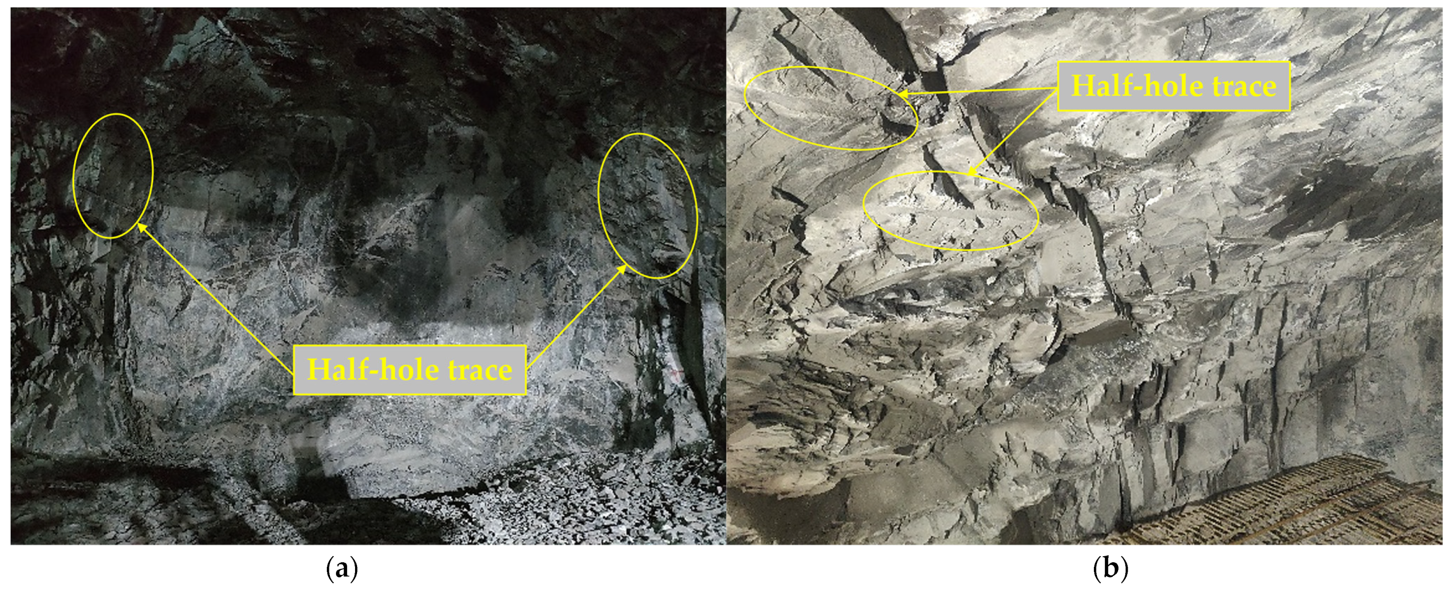
The study focuses on an extra-long tunnel with a length exceeding 10 km. Smooth blasting method has been employed to enhance efficiency. Firstly, auxiliary cross-holes have been installed to increase the excavation working surface, facilitating the construction of a long tunnel with shorter strikes. Additionally, large-scale machinery such as three-arm rock drilling carts, hydraulic trestle bridges, and intelligent lining carts have been utilized for support operations, enabling mechanized and rapid construction of the extra-long tunnel. However, certain engineering challenges have arisen during construction, significantly impacting efficiency. For instance, the drilling and blasting method employed exhibits poor blasting effects, and difficulties arise in the construction of auxiliary cross-holes, resulting in low efficiency. Furthermore, issues regarding the adaptability of large-scale machinery to construction conditions are prevalent. Figure 2 illustrates the blasting effect of the drilling and blasting method employed in construction.
The original design utilizes conventional blasting parameters, with a peripheral hole distance of approximately 0.6 m and a distance of 0.8 m between the auxiliary hole and the tunnel excavation contour line. The hole spacing ranges from 1 m to 1.4 m. However, during the initial stages of construction, these parameters prove to be poorly adaptable to the peripheral rock conditions of the long and hard rock tunnel. Insufficient precision in the drilling and charging operations results in significant overbreak and underbreak in the tunnel blasting peripheral rock cross-section profile. The charging structure of the peripheral holes is located at the bottom, with no utilization of smooth blasting for construction. As depicted in Figure 2, the half-hole trace rate on the tunnel wall after blasting is low, resulting in an uneven wall surface and evident overbreak and underbreak. The maximum value of overbreak at the measuring point of the tunnel section is close to 0.8 m. A significant portion of the explosive energy during blasting is concentrated at the bottom of the hole, leading to pronounced local crushing after blasting. This particularly damages the surrounding rock, posing potential risks to the safety, stability, and quality control of the surrounding rock.
Consequently, it is crucial to promptly adjust and optimize the parameters of smooth blasting to effectively control the overbreak and underbreak during tunnel blasting. Additionally, the fractal characteristics of the tunnel profile before and after the optimization of smooth blasting are analyzed using multifractal theory. The flowchart of the study is presented in Figure 3.

2.2. Optimization of Tunnel Smooth Blasting

To address the issue of overbreak and underbreak, the smooth blasting coefficients were preliminarily optimized and determined. This involved considering factors such as the number of holes, hole spacing, charge amount, and detonation method, using smooth blasting theory. The design of the smooth blasting parameters took into account the physical and mechanical properties of the surrounding rock, as well as the development of internal joints and fissures in the rock mass.

2.2.1. Spaced Decoupled Charge Blasting

The peripheral hole blasting parameters and charging structure are crucial factors influencing the smooth blasting effect. The original peripheral hole blasting parameters for the tunnel are as follows.
  • Blasting equipment
The explosives are No. 2 emulsified explosives. The length and diameter of the cartridge are 200 mm and 32 mm, respectively, and the weight of a single cartridge is 200 g. The detonator is a millisecond differential time-delay detonator with a detonating cord.
2.
Parameters of hole arrangement
The layout of smooth blasting holes with spaced decoupled charging is depicted in Figure 4. The excavation method employed at the site is one-time blasting in full section with invert arch. A total of 65 peripheral holes were set up, with a spacing of 50–60 cm and a hole depth of 420 cm. The auxiliary holes adjacent to the peripheral holes were positioned 80 cm away from the tunnel excavation contour line, resulting in a light blasting layer thickness of 76 cm. The parameters of the blast holes are presented in Table 2.
3.
Charge structure
The decoupled charging structure is employed for the peripheral hole blasting. Each hole has a loading capacity of 0.5 kg, with a loading concentration of 0.2 kg/m and an interval of 55 cm. The uncoupling coefficient is 1.31. The plugging material used is a pre-mixed flexible mortar, with a plugging length of 60 cm. The spacing and uncoupling loading structure are depicted in Figure 5. The other holes are loaded continuously.
For the peripheral holes of the decoupled charging method, smooth blasting is conducted based on the characteristics of the surrounding rock. Detonating cord connection is utilized, and the spacing of the peripheral holes is strictly controlled. The holes are detonated using multi-stage detonators, with a detonation order of hollowing holes, auxiliary holes, base plate holes, and smooth blasting perimeter holes. The detonation time difference between adjacent holes is not less than 50 ms. The detonation time difference control between the holes in a row and the surrounding hole is between 100 to 150 ms. The quality of hole plugging is an important factor that affects the smooth blasting effect. To maximize the explosive energy and extend the effective action time of the blast gas, a mixture of clay and fine sand with good viscosity is used for plugging the holes. This aims to improve rock fragmentation and the effect of smooth blasting on peripheral holes.

2.2.2. Bidirectional Shaped Charge Blasting

In the 1970s, shaped charge blasting was applied in geotechnical engineering. Shaped charge blasting fully utilizes the high compressive and low tensile properties of rocks to form tangential tensile stress. The coupling effect between the shaped charge tank and the explosive charge is perpendicular to the direction of the shaped charge [56,57]. Tangential tensile stress causes initial cracks on the wall of the blast hole. When the radial tensile stress generated by the explosion stress wave acts on the rock between two adjacent main cracks, the rock can be pulled apart to form a circumferential crack, which can connect with each other, thus forming rock fracture. The remaining gas pressure ejects the rock mass, separating it from the parent rock and maximizing the conversion of detonation pressure into tensile action on the surrounding rock.
Due to the complex geological conditions of the extra-long hard rock tunnel project, the smooth blasting effect is not ideal in many instances. To achieve the best smooth blasting effect, the bidirectional shaped charge blasting technology is introduced into the smooth blasting construction of the tunnel. The peripheral hole blasting parameters are reasonably adjusted. The bidirectional shaped charge blasting hole program and the order of detonation are similar to the spaced decoupled charging smooth blasting technology. This study focuses on adjusting the peripheral hole parameters and charge structure.
1.
Peripheral hole parameters
Peripheral hole depth is 420 cm, the number of peripheral holes is adjusted to 51, the hole spacing is adjusted to 60~70 cm, and the thickness of the light explosion layer is adjusted to 60 cm.
2.
Charge structure
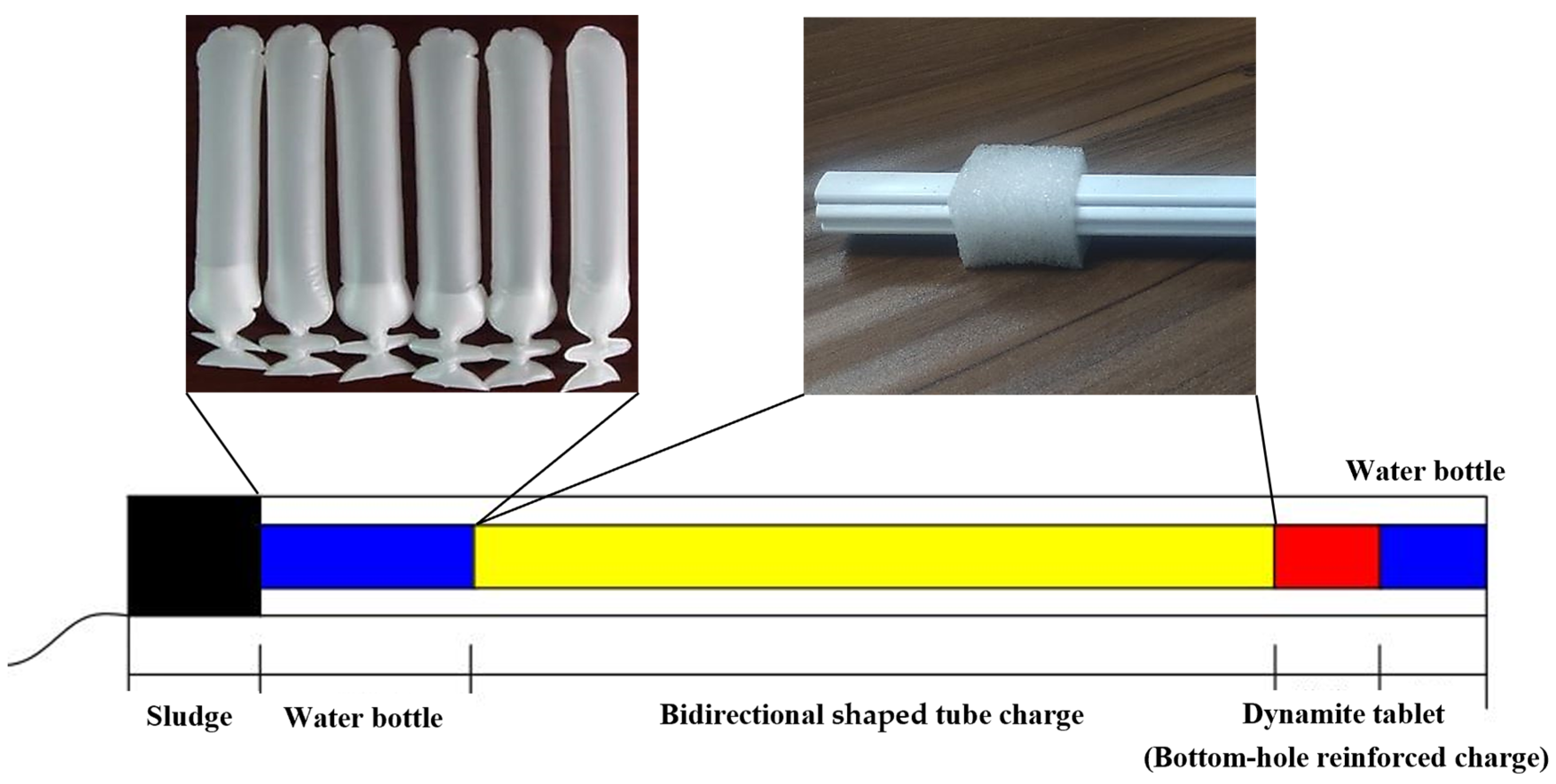
The structure of the glossy blasting charge for bidirectional shaped charge blasting is shown in Figure 6. The peripheral hole is continuously loaded with bidirectional shaped tube charge. Considering that the bottom of the hole is subject to greater rock entrapment, the charge is reinforced at the bottom of the hole. In order to improve the utilization rate of blasting energy, water bags were added at the bottom of the hole and the hole opening. The incompressibility of water is utilized to increase the time of action of the blasting load. The length of the poly energy pipe is 250 cm, its equivalent diameter is 23.5 cm, the charge of a single hole is 0.6 kg, the concentration of the charge is 0.15 kg/m, the non-coupling coefficient is 1.79, and the length of the blast mud blockage is 40 cm. The other holes are loaded in the same structure as the conventional smooth blasting.
The blasting test utilized a specialized PVC pipe with symmetrical grooves on both sides, resulting in an equivalent diameter of 23.5 cm. For tunnel blasting, conventional water bags were employed, filled with water, with a diameter of 3.5 cm and a length of 25 cm.

2.3. Tunnel Profile Measurement

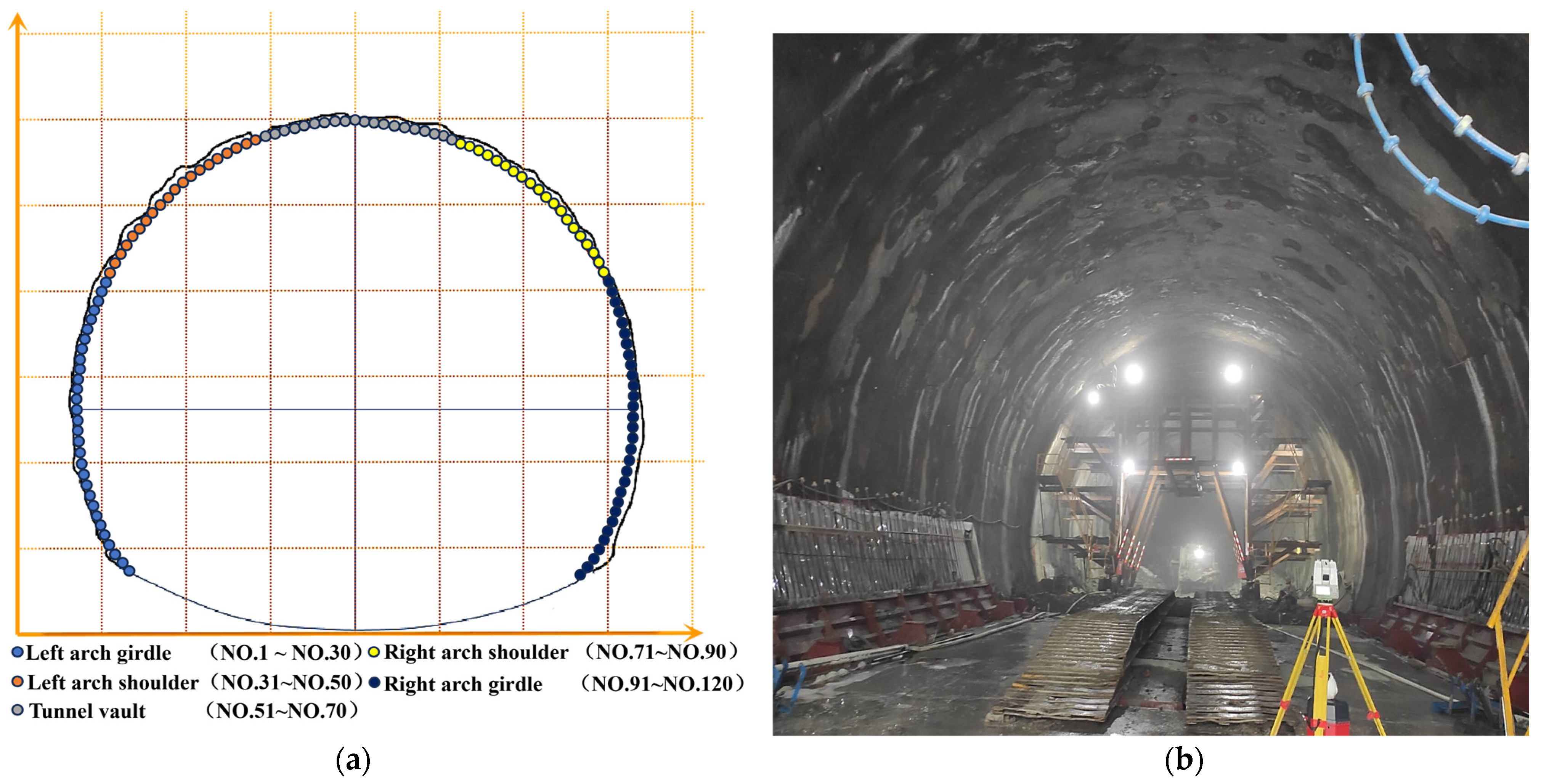
The laser profilometer, also known as the laser tunnel limiter, is widely used in tunnel section measurement due to its simplicity, high accuracy, and intuitive image. It operates based on the polar co-ordinate method, which combines polar co-ordinate measurement with computer technology and specialized graphic post-processing software. This allows for the convenient acquisition of the actual excavation contour line of the measured tunnel section and a comparison with the design contour line to obtain overbreak and underbreak data. The laser profiler can be used to measure both the current section and the forward section, with the current section primarily used for measuring overbreak and underbreak.
The distance between each measuring site should be selected based on the specific conditions of the tunnel site. To facilitate subsequent statistical analysis of the overbreak and underbreak data, 120 uniformly distributed measurement points are typically used for each measurement section. Figure 7 illustrates the design and field implementation of the tunnel profile overbreak and underbreak measurement.

2.4. Multifractal Detrended Fluctuation Analysis Methodology

Fractal theory can be categorized into geometric self-similarity or uniform fractals, and statistical self-similarity or non-uniform fractals, also known as multifractals. Geometric self-similarity is often described using a simple fractal dimension (D), while statistical self-similarity requires the multifractal spectrum f α α to characterize it. The multifractal spectrum, also known as the singularity spectrum, is a mathematical tool used to describe the nature of multifractals [58]. It is utilized to analyze data with a multifractal structure, such as images and time series. The multifractal property refers to the existence of several different fractal dimensions in a system, where physical quantities exhibit different fractal characteristics at different scales. The multifractal spectrum measures the fractal dimensions at these different scales by dividing the fractal body into several small intervals. The singularity index α represents the fractal dimension of each subinterval, and the corresponding f α values represent the fractal dimension of each subinterval. Intervals with the same α value form a subset of the fractal, resulting in an infinite sequence of different α values. The multifractal spectral function, f α , is obtained from this infinite sequence.
The MF-DFA is an extension of detrended fluctuation analysis (DFA) that effectively reveals the dynamic behaviors in nonlinear and nonsmooth signals. Compared to traditional multifractal computation methods, MF-DFA utilizes the length of the sequence data and divides the sequence into equal time lengths in both directions [59]. The polynomials are fitted to each segment using the least squares method to eliminate the influence of the non-stationary trend of the time series. MF-DFA analyzes the scalar behavior of the series at different levels using different orders of fluctuation functions, allowing for a fine characterization of the fractal features and revealing the multifractal features hidden in non-stationary time series [60].
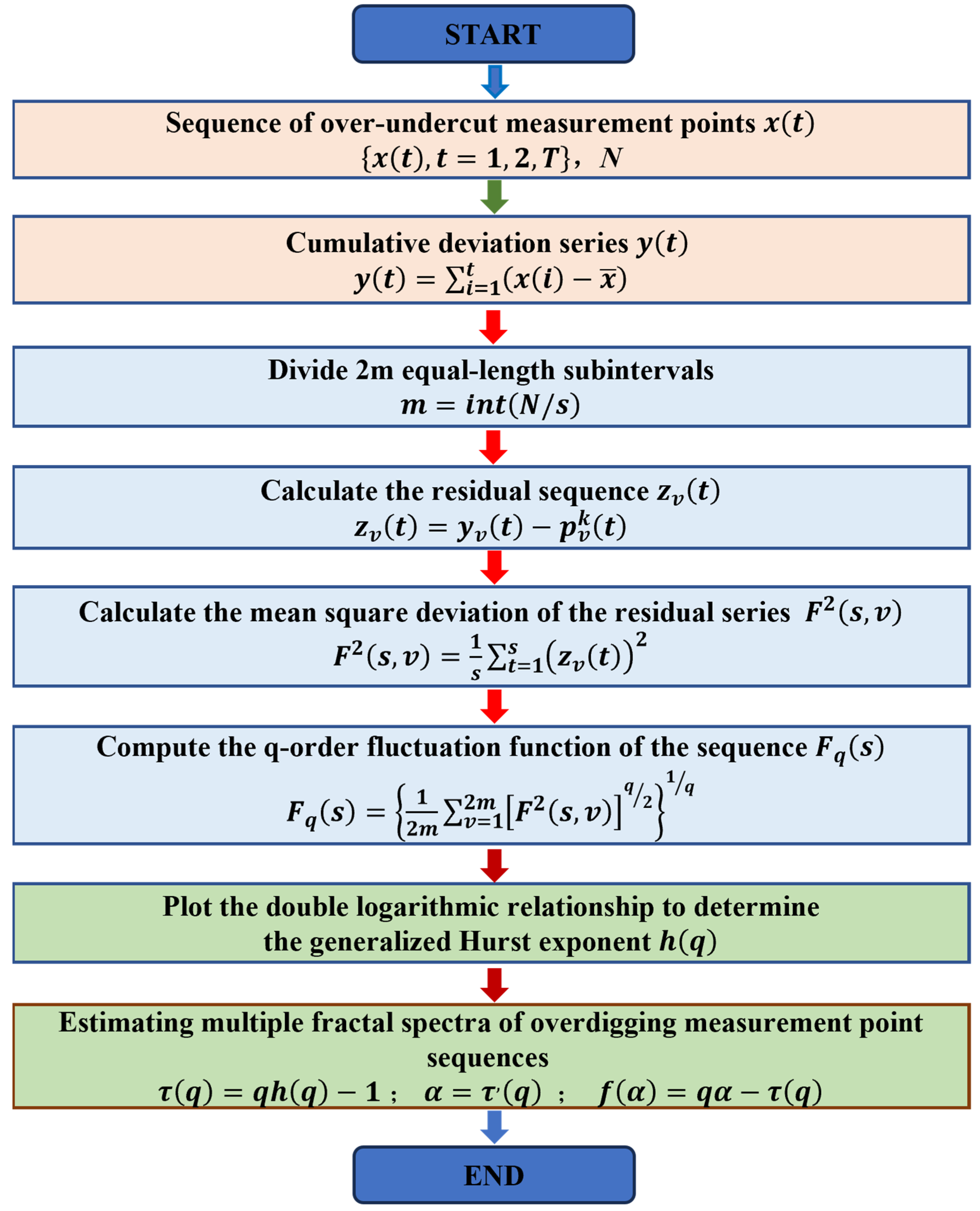
The calculation of MF-DFA involves five steps. The detailed calculation process is shown in Figure 8.
Step 1: Given a nonlinear, nonsmooth time series x t with a sequence length of N and a sequence mean of x ¯ , calculate the cumulative deviation series y t with respect to the mean x ¯ :
y t = i = 1 t x i x ¯
Step 2: The sequence is y t , equalized in terms of time scale s and divided into m equal-length continuous and non-overlapping subintervals:
m = i n t N / s
Since the length of the time series, N, may not be an integer multiple of s, there will be residual values in the division process. To fully utilize the data information, a reverse-order processing method is applied. This means that, after the initial positive-order division, the same operation is repeated starting from the end of the sequence. As a result, 2 m equal-length subintervals are obtained.
Step 3: A trend is fitted to each subinterval and subtracted from the original time series. The residual series obtained is denoted as z v t :
z v t = y v t p v k t
Specifically, y v t represents the v-th subinterval, while p v k t represents a k-th-order fitting polynomial for the v-th subinterval. Here, v takes values in the range [1, 2 m] and t takes values in the range [1, s].
Step 4: The residual sequence, z v t , is calculated for each subinterval v. This forms the F 2 s , v dataset:
F 2 s , v = 1 s t = 1 s z v t 2
Step 5: The mean value of the F 2 s , v dataset is calculated, and the q-order volatility function of the series, F q s , is obtained using Equation (4):
F q s = 1 2 m v = 1 2 m F 2 s , v q 2 1 q
The value of q can be any non-zero real number and is related to the degree of exposure to fluctuations in F q s . It is worth noting that, when q = 2, the MF-DFA degenerates to the standard DFA. Additionally, when q = 0, there is a limiting form of Equation (4):
F 0 s = e x p 1 4 m v = 1 2 m ln F 2 s , v
Conventional MF-DFA is prone to pseudo-fluctuations in the division of intervals, causing interference in the subsequent analysis. In addition, the timing length may not be able to rectify the sub-interval length, resulting in redundancy of data. If the redundancy is ignored, it will cause the loss of data information. If the reverse-order processing method is adopted, the order of the original data will be disturbed, affecting the acquisition of information. In view of this, considering the special characteristics of the over-undercut data of the tunnel profile, a sliding window is used here to optimize the way of dividing subintervals of the traditional MF-DFA. A window of a certain length is used to slide the values on the sequence according to a certain step size to reduce the pseudo-fluctuation of the data and make full use of the data information. Let the length of the window be s, the length of the sequence be N, and take the sliding step to be 1; then, the number of sub-intervals obtained in one run is Ns + 1, and we replace Equations (5) and (6) with Equation (7):
F q s = 1 N s + 1 v = 1 N s + 1 F 2 s , v q 2 1 q   , q 0   e x p 1 2 N s + 1 v = 1 N s + 1 ln F 2 s , v   , q = 0
The q-order fluctuation function corresponding to a certain scale s can be obtained by the above steps. By varying the values of s and repeating the above steps, a series of s F q s point values are obtained. If there is long-range correlation in this time series, there will be a power law relationship between s and F q s as shown in Equation (8):
F q s s h q
Taking logarithms on both sides of the above equation gives the form of Equation (9):
lg F q s = h q lg s + lg b
where F q s is the q-order volatility function of the series, h q is the corresponding generalized Hurst exponent, and b is a constant coefficient.
By creating a double logarithmic scatterplot of lg F q s lg s and fitting it, the slope can be determined as the generalized Hurst exponent, h q . If h q is a constant, this indicates that the sequence is unifractal without multifractal features. However, if h q is a nonlinear subtractive function of q, this suggests that the sequence exhibits multifractal characteristics. Specifically, when h q < 0.5, the sequence demonstrates a memory process with inverse persistence. When h q = 0.5, the sequence behaves as an uncorrelated stochastic process. When h q > 0.5, the sequence exhibits a memory process with positive persistence. Moreover, when h q > 1, the sequence behaves as a long-range positively correlated process with strong non-stationarity.
The fractal intensity and fractal singularity of a time series can usually be characterized by the multifractal spectrum f α to be characterized by solving Equations (10)–(12) as follows:
τ q = q h q 1
α = τ , q
f α = q α τ q
The Renyi index τ q is a scalar function that can be used to determine whether a sequence exhibits multifractal characteristics. If τ q is a nonlinear up-convex function of q, this suggests that the sequence is multifractal. On the other hand, if τ q is a linear function of q, this indicates that the sequence has a single fractal feature. Therefore, the Renyi index is often used as a criterion to determine the multifractality of a sequence. The singular intensity α , and the multifractal spectrum f α , are also important in characterizing the multifractal properties of a sequence. When the plot of α f α is convex with a single peak and resembles a quadratic function, this suggests that the sequence has a multifractal feature. On the other hand, when α f α clusters around a point, this indicates that the sequence is unifractal.
In addition, the fractal spectral width Δ α and the fractal intensity Δ h are commonly used to quantitatively characterize the multifractal properties of a sequence. Δ α mainly reflects the singularity of the over-undercut data of the tunnel profile and the spatial variability of the sequence. On the other hand, Δ h mainly reflects the fractal intensity of the sequence and is proportional to the parameter values:
Δ h = max h q min h q
Δ α = max α q min α q

3. Results and Discussion

3.1. Analysis of the Optimized Effect of Tunnel Smooth Blasting

3.1.1. Smooth Blasting with Spaced Decoupled Charge

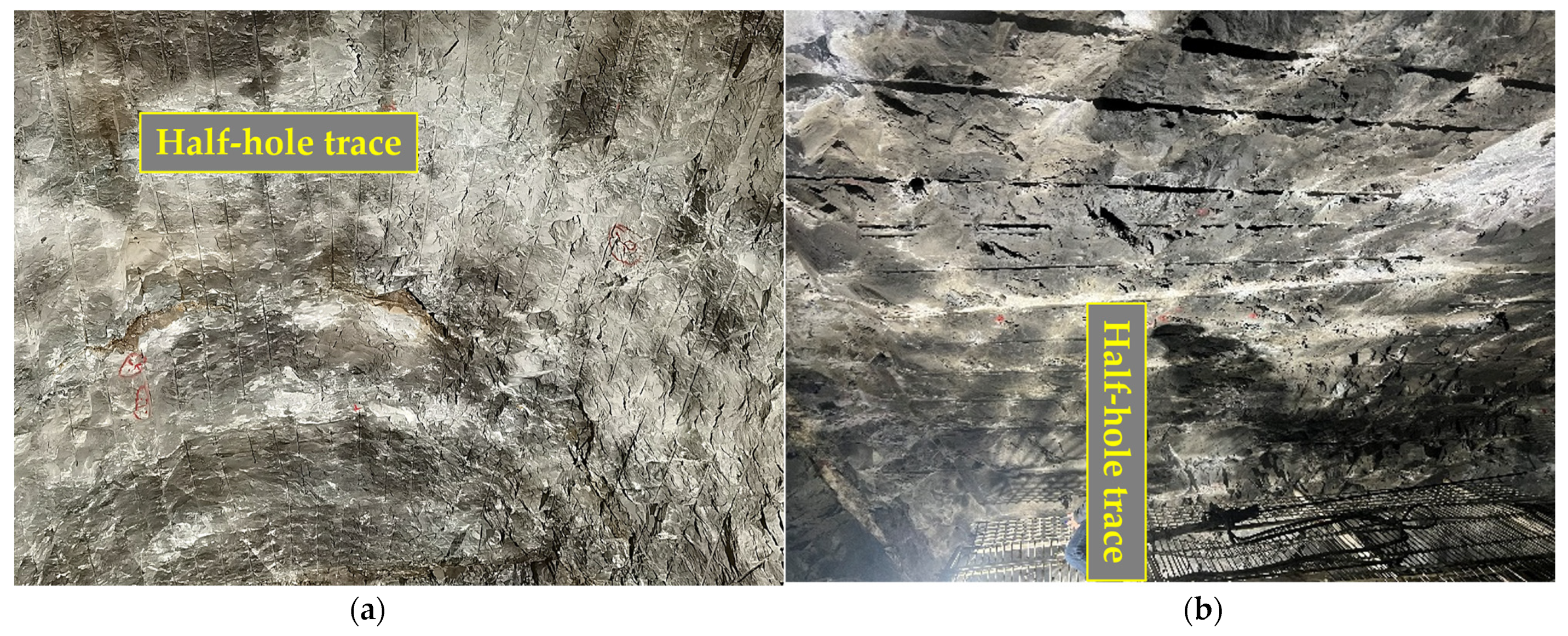
Based on the theory of spaced decoupled charge smooth blasting technology, the aforementioned decoupled charge blasting design was applied in the test section of tunnel excavation. The resulting effect of the smooth blasting is depicted in Figure 9.
As can be seen from Figure 9, the tunnel profile was basically shaped after blasting. However, the tunnel wall exhibits unevenness, and the traces of half-hole marks on the tunnel wall are not clearly visible. The rate of half-hole marks on the tunnel wall is 56%, and the maximum unevenness exceeds 30 cm, indicating a noticeable occurrence of overbreak and underbreak. Upon analysis, it was found that, although the compressive strength of the tunnel rock reached 118.6 MPa, the integrity of the surrounding rock was poor, with certain joints and fissures. Additionally, the deep surrounding rock of the peripheral holes experienced a significant clamping force, resulting in insufficient blasting effectiveness. Consequently, the incomplete separation of the light blasting layer of rock led to overbreak and underbreak.

3.1.2. Smooth Blasting with Bidirectional Shaped Charge

To address this issue, the design scheme of bidirectional shaped charge blasting, based on the theory of smooth blasting technology, was implemented in the test section of tunnel excavation. After blasting the peripheral hole with a bidirectional shaped charge, the improved smooth blasting effect is shown in Figure 10.
As can be seen in Figure 10, the glossy smooth effect was significantly enhanced after the tunnel was loaded with the bidirectional shaped charge. The excavation contour line of the tunnel appeared flat after blasting, and the traces of half-hole marks on the tunnel wall were clearly visible. The rate of half-hole marks on the tunnel wall reached 89%, and the maximum unevenness was less than 10 cm. Laser sectional meter measurements confirmed that the tunnel section profile was nearly free of overbreak and underbreak phenomena.

3.1.3. Overbreak and Underbreak of Tunnel Profile of Smooth Blasting

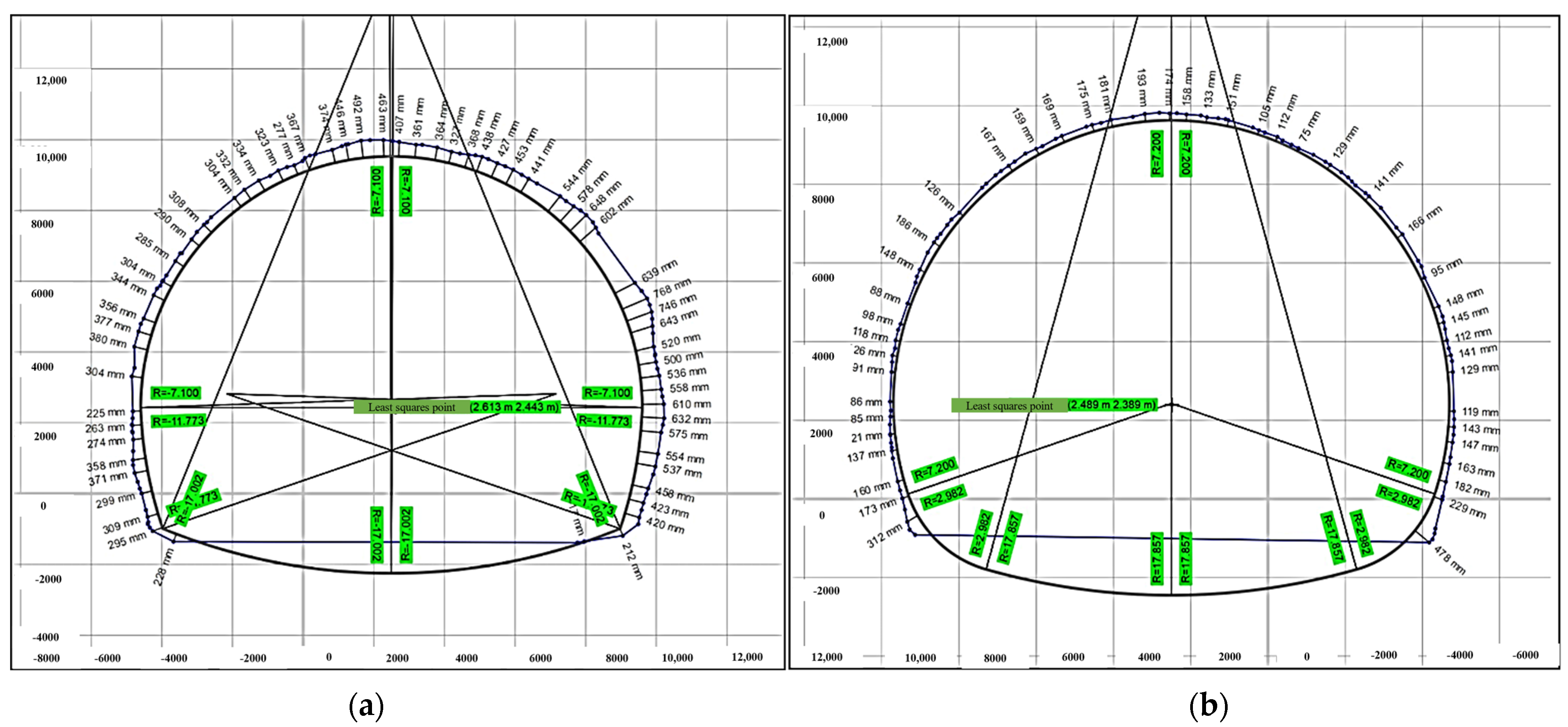
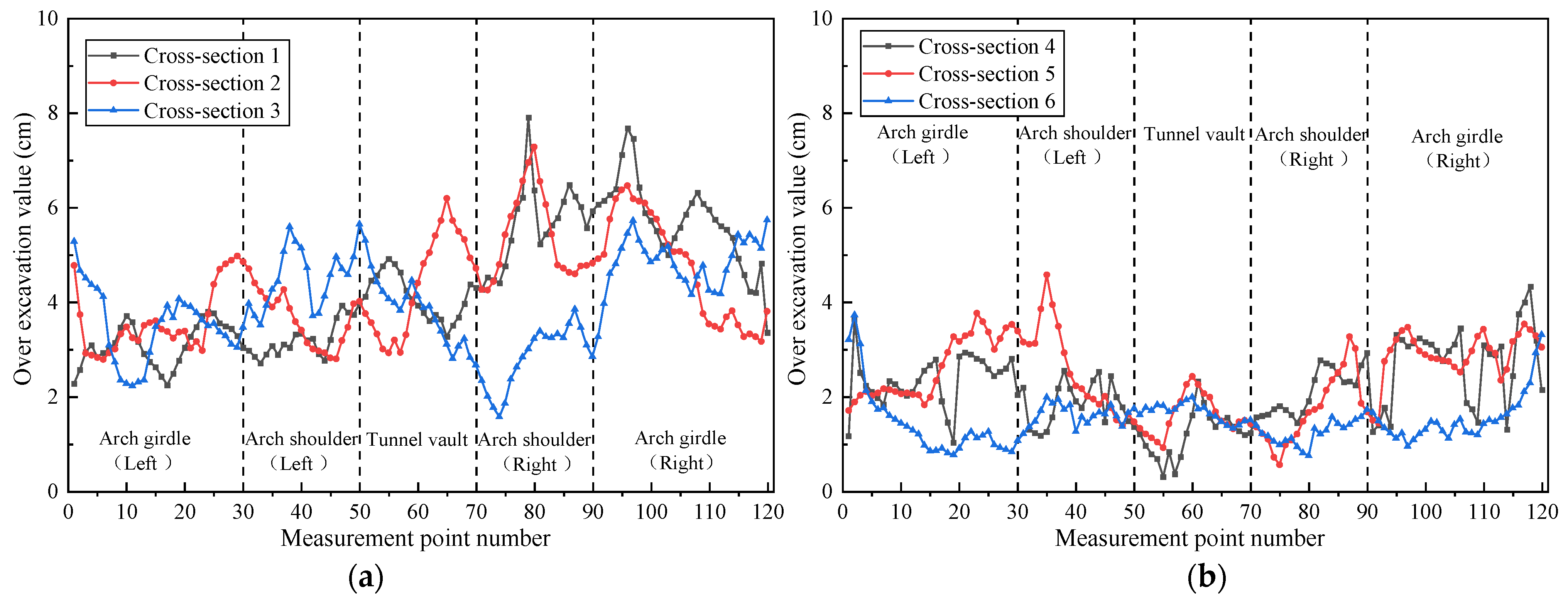
For the long hard rock tunnel perimeter rock section, two different smooth blasting technologies, namely, spaced decoupled charging and bidirectional shaped charge, were tested. Multiple groups of field tests were conducted using distinct smooth blasting programs. A laser profiler was utilized to scan the tunnel profile after blasting, and the scanning results are presented in Figure 11. Based on the scanning results, data on tunnel overbreak and underbreak were extracted. The distribution curves of the overbreak and underbreak of the tunnel profile are depicted in Figure 12.
According to the scanning results shown in Figure 11, the overbreak and underbreak area of the interval decoupled charge blasting section is calculated to be 13.01 m2, while the bidirectional shaped charge blasting only resulted in an overbreak and underbreak area of 4.61 m2. This indicates that the bidirectional shaped charge blasting has a significantly better smooth blasting effect compared to the interval decoupled charge blasting. As depicted in Figure 12, the average overbreak value for each measurement point in the interval decoupled charge blasting is 4.21 cm, with a maximum overbreak value of 7.91 cm occurring at the right arch shoulder. The overbreak at the right arch shoulder and arch waist is more pronounced in the interval decoupled charge blasting. On the other hand, for the bidirectional shaped charge blasting, the average overbreak value at each measurement point is 1.99 cm, with a maximum overbreak value of 4.58 cm occurring at the left arch shoulder. The overbreak values of each area of the tunnel section after bidirectional shaped charge blasting are not significantly different, indicating that the smooth blasting effect is better than that of the interval decoupled charge blasting.
To further compare the blasting effects of the two charging methods in extra-long hard rock tunnels, statistical analysis was conducted, as shown in Table 3.
It can be observed from Table 3 that the bidirectional shaped charge blasting resulted in a decrease of 14 smooth blasting holes compared to the interval decoupled charge blasting, with a 21.5% decrease in the number of holes around the optimized blasting scheme. Additionally, the half-hole trace rate on the tunnel wall increased from 56% to 89%, improving the utilization rate of the shell hole. The explosive dosage of peripheral holes was reduced by 5.8%, leading to an improved utilization rate of blasting energy. These improvements effectively addressed the issue of overbreak and underbreak in the tunnel and saved 8.4 m3 of concrete cubic meters for each meter of advance. As a result, the optimized smooth blasting scheme ensured the safe and efficient completion of the extra-long hard rock tunnel.

3.2. Multifractal Characteristics of Tunnel Profile Overbreak

3.2.1. MF-DFA Key Parameters Determination

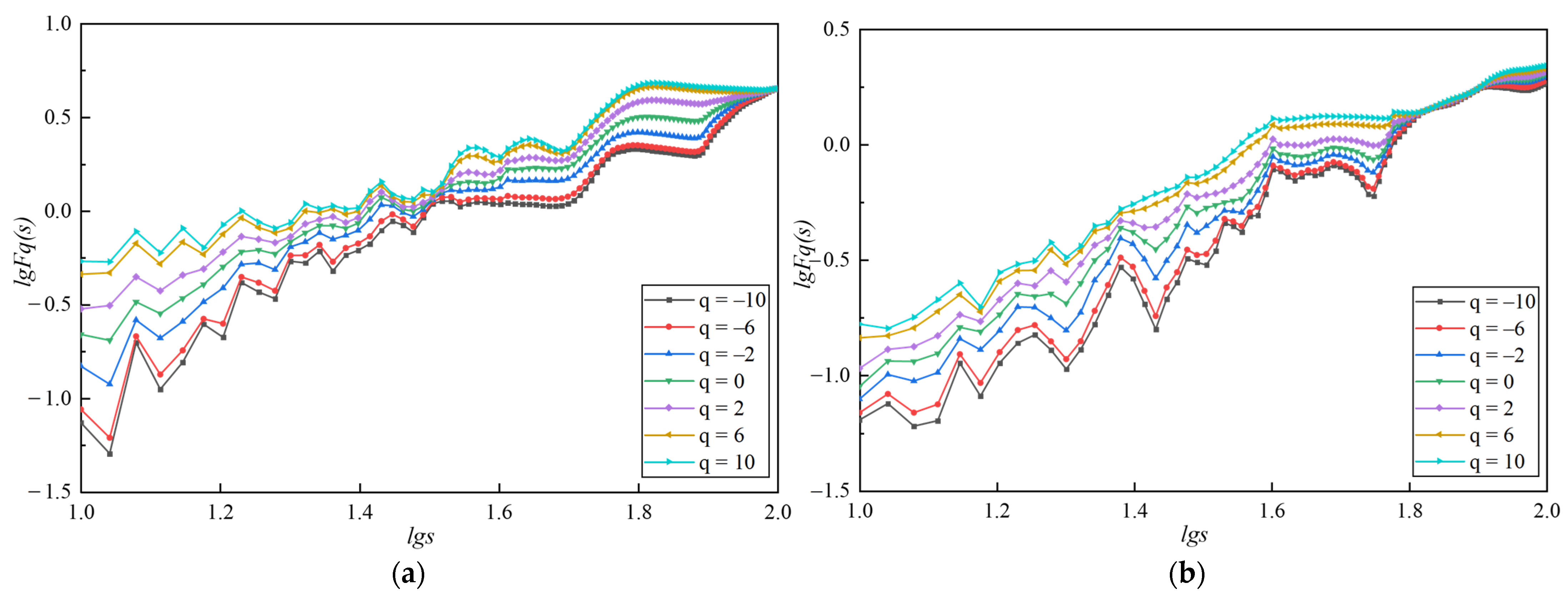
The characteristics of the non-stationary time series obtained under different computational parameters vary significantly, including the signal time window length and fluctuation trend. Therefore, it is necessary to try different key parameters and preset them to obtain more reliable results. The parameter values have different effects on the calculation results. In order to analyze the fractal characteristics of the overbreak and underbreak of the tunnel profile before and after the optimization of smooth blasting more efficiently using multifractal theory, multifractal analysis is conducted on the overbreak characteristics of the tunnel profile. The fluctuation order q is taken in the range of [−10, 10], and a double logarithmic scatter plot of lg F q s lg s is plotted. Least squares fitting is used, and the slope of the fitting line is the generalized Hurst exponent h q . Taking a set of overbreak characteristics of the tunnel profile after spaced decoupled faceted blasting and bidirectional shaped charge blasting as an example, the q-order fluctuation function F q s s is fitted using double logarithmic scale, as shown in Figure 13.

3.2.2. Multifractal Characterization of Overbreak Section Profile

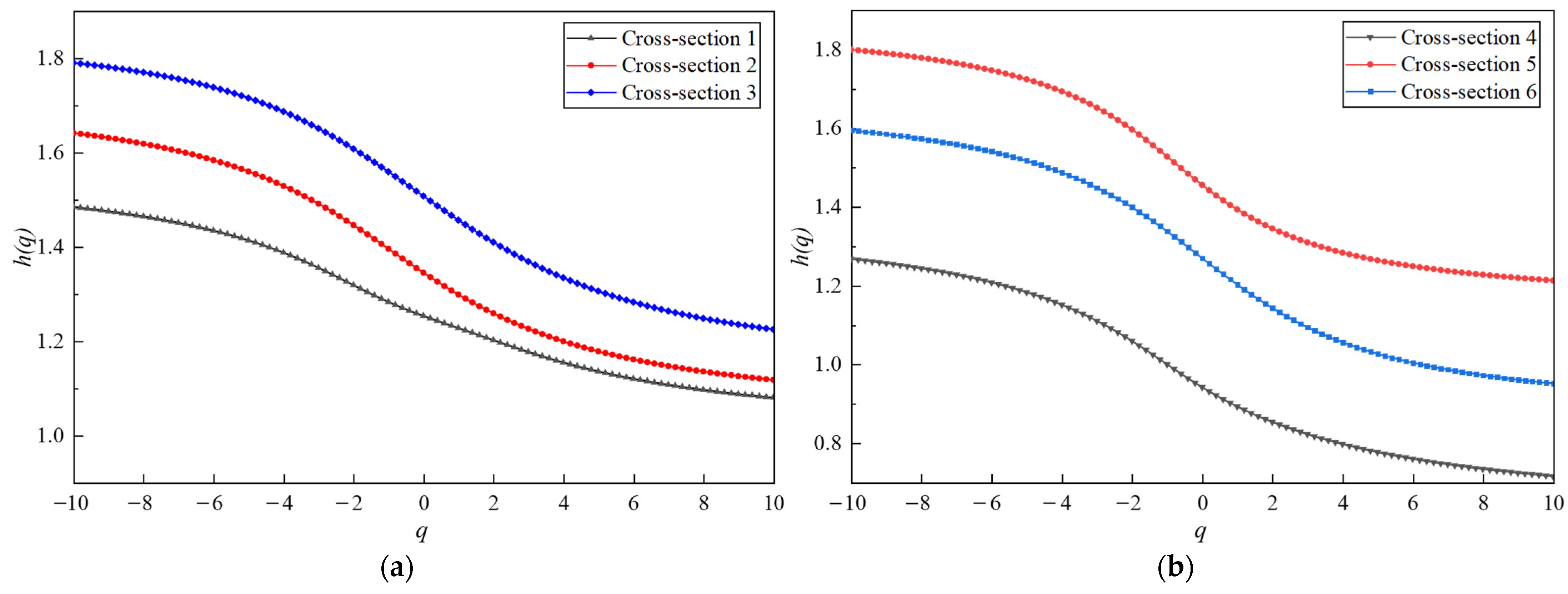
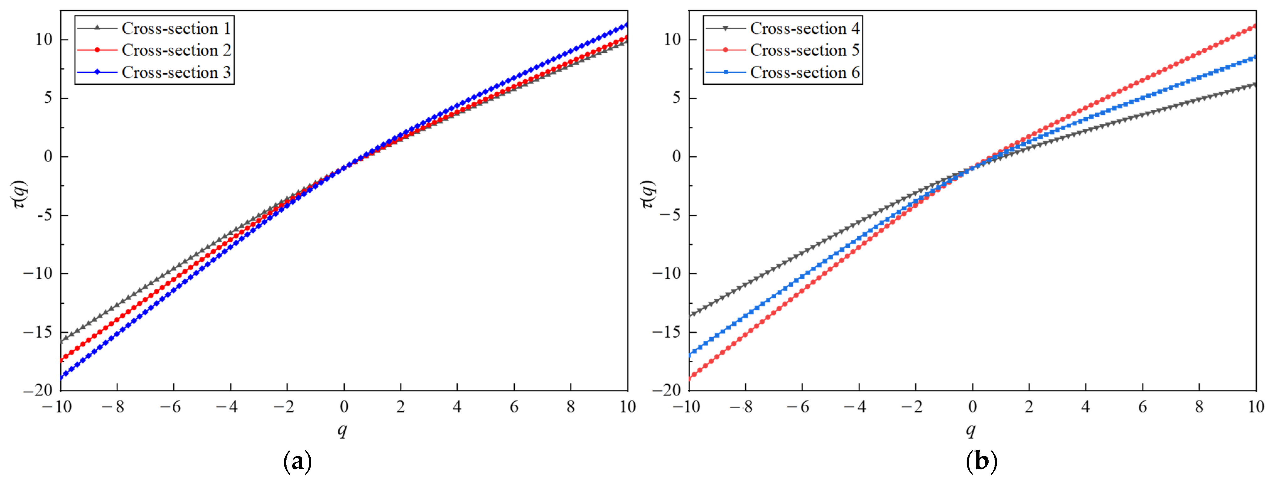
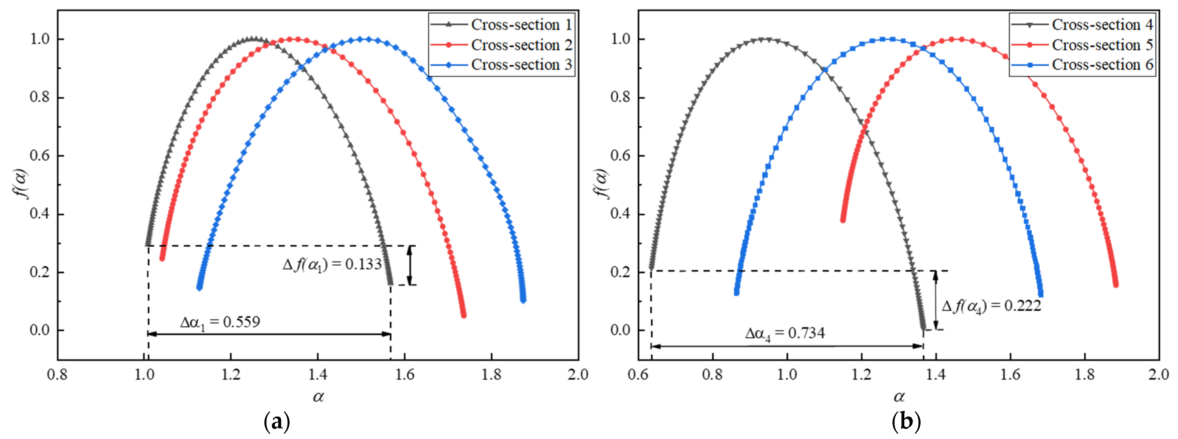
A sliding time window optimization MF-DFA is then used to perform a multifractal analysis on the sequence of overbreak points of the tunnel profile. The fluctuation order q is in the range of [−10, 10], the scale s is in the range of [10, 100], and the sliding window step is 1. The changes of the generalized Hurst exponent of the sequence of overbreak points are shown in Figure 14. The variation of the scalar function τ q of the overbreak point sequence is shown in Figure 15. The multifractal spectrum of the overbreak measurement point sequence is shown in Figure 16.
It can be observed from Figure 14 that the generalized Hurst exponent of each overbreak measurement point sequence is not constant for both spaced decoupled charging and bidirectional shaped charge blasting when q varies between [−10, 10]. Instead, it shows a nonlinear decreasing trend with q, indicating that each sequence of overbreak measurement points exhibits obvious multifractal characteristics. It is not sufficient to describe them with a single fractal theory. Under different fluctuation orders q, the generalized Hurst exponent curves of partially spaced decoupled charge blasting are concentrated in the lower fluctuation range compared to bidirectional shaped charge blasting, indicating a weaker multifractal nature. However, the values of the spaced decoupled charge and bidirectional shaped charge blasting are significantly larger than 0.5. These h q values indicate that the sequence of overbreak measurement points exhibits good memory and long-range correlation from the whole to the local components, combining non-stationarity and randomness.
Based on the h q , the scaling function τ q is calculated. From Figure 15, it can be observed that the scalar function of each overbreak measurement point sequence shows good consistency for both spaced decoupled charging and bidirectional shaped charge blasting. The function is up-convex, satisfying τ q = 1 and exhibiting an overall nonlinear relationship. This further confirms the multifractal characteristics of the overbreak measurement point sequence.
Figure 16 shows the multifractal spectra of the overbreak point sequence of the tunnel profile under different smooth blasting plans. The spectra display a single convex distribution, similar to a quadratic function curve. The local scales of the multifractals in the overbreak point sequences vary, indicating the diversity of local changes at different moments. The singular intensities α are mainly concentrated on the two sides of the image, reflecting the uneven distribution of the fractal structure in the overbreak point sequence. This uneven distribution further confirms the multifractal characteristics of the measurement point sequence. The multifractal spectra of the spaced decoupled charge blasting and bidirectional shaped charge blasting show good overall synergy and stable development status. The spectra of the overbreak point sequences in cross-section 4 and cross-section 5 exhibit obvious right hooks, indicating that small fluctuations have a slightly dominant influence in the overbreak point sequences of these sections. The fractal dimension of the sub-intervals that characterize the overbreak point sequence with the same singularity index α is the same. The fractal dimension of the sub-intervals in the overbreak point sequence is related to the distribution characteristics and fractal strength of the overbreak point sequence.
In Figure 16, Δ α represents the multifractal spectral width, which characterizes the multifractal strength of the sequence at the measurement point and the complexity of the fluctuations. A larger Δ α indicates a stronger multifractal strength and more intense and complex fluctuations. The opposite is also true. Δ f α represents the proportion of large and small fluctuations in the sequence. A larger proportion of small and medium fluctuations in the sequence leads to a larger Δ f α . The calculation method for α and Δ f α can be expressed as follows:
Δ α = α m a x α m i n
Δ f α = Δ f α m a x Δ f α m i n
Combining Figure 14 and Figure 16, it can be observed that the fractal intensity   Δ h and the width of the multifractal spectrum Δ α of the fractal spectrum of the overbreak measurement point sequence in cross-section 1 are minimized. This is because the overbreak measurement point sequences in the same section are not independent of each other but are related to each other to some extent. Overall, the values of the six cross-section overbreak point sequences are close to each other, and the fluctuations have similar odd values. The Δ α values are close to each other, indicating the similar singularity and spatial variability of the fluctuations. The probability distribution ranges of the fluctuations at each measurement point are relatively close to each other, but the fractal intensity Δ h values show slight differences. The fractal strength of the overbreak sequence in the tunnel section after the bidirectional shaped charge blasting is slightly stronger than that of the spaced decoupled charge blasting. Based on the actual situation, it can be initially inferred that the optimization of the tunnel smooth blasting significantly reduces the phenomenon of overbreak in the tunnel profile, leading to differences in the multifractal characteristics of the measurement points in each cross-section.
The statistics of multifractal features for the over-undercut sequence of the tunnel profile under different smooth blasting plans are calculated, and the results are shown in Table 4.
Comparing the widths of the multifractal spectra Δ α of the cross-section profile overbreak point sequences, it can be observed that the width of the multifractal spectrum for the spaced decoupled charge blasting is slightly smaller than that for the bidirectional shaped charge blasting. This indicates that the bidirectional shaped charge blasting results in a larger multifractal intensity in the overbreak point sequence and slightly more complex fluctuations. Furthermore, comparing the proportion of large and small fluctuations Δ f α in the profile undercut point sequences, it can be seen that the bidirectional shaped charge blasting results in a larger proportion of small and medium fluctuations.
These findings align more closely with the actual situation and indicate that the optimization of tunnel smooth blasting through bidirectional shaped charge blasting significantly reduces the phenomenon of overbreak in the tunnel profile. The intensity of the multifractals in the measurement point sequence is larger, and the fluctuation of the cross-section profile overbreak data is slightly more complex, with a larger proportion of small fluctuations.

4. Conclusions

For extra-long tunnels with complex and variable perimeter rock grades, the untimely adjustment of smooth blasting parameters often leads to a significant number of overbreak and underbreak, resulting in project delays. Therefore, this paper focuses on conducting in-depth research on smooth blasting technology for extra-long hard rock tunnels in the context of a high-speed rail project. The research approach combines theoretical analysis, field tests, and multifractal analysis to provide comprehensive insights. The main research conclusions are as follows:
  • The peripheral hole charging structure and blasting parameters are improved and optimized to enhance the effect of tunnel smooth blasting. The implementation of the bidirectional shaped charge significantly improves the smooth blasting effect. After blasting, the tunnel excavation contour line becomes flat, and the half-hole trace marks on the tunnel wall become more distinct. In comparison to spaced decoupled charging blasting, the smooth blasting effect with a bidirectional shaped charge is notably superior.
  • The laser profiler is utilized to measure the actual excavation contour line of the tunnel section, obtaining specific data on overbreak and underbreak. A further quantitative comparison of the optimization effect of smooth blasting parameters is conducted. It is observed that the overbreak and underbreak value of each area of the tunnel section after bidirectional shaped charge blasting does not differ significantly, and the smooth blasting effect is evidently better than that of spaced decoupled charge blasting.
  • MF-DFA is employed to analyze the multifractal features of the overbreak point sequences of the tunnel profile under different smooth blasting plans. It is concluded that both spaced decoupled charge and bidirectional shaped charge blasting result in measurement point sequences with multifractal features in the overbreak area. The statistical calculation results of the multifractal features of the tunnel profile under different smooth blasting plans align more closely with the actual situation.
The smooth blasting tests conducted in this study were carried out in a single surrounding rock grade. Future studies can focus on optimizing the smooth blasting parameters and conducting the multifractal characterization of the sequence of overbreak and underbreak points for different surrounding rock grades of tunnels.

Author Contributions

Methodology, D.L. and Y.T.; software, W.Z.; validation, W.Z. and W.Q.; formal analysis, W.Z. and W.Q.; data curation, D.L. and R.Z.; writing—original draft preparation, W.Z.; writing—review and editing, D.L. and Y.T.; project administration, W.Q. and R.Z.; funding acquisition, D.L. and Y.T. All authors have read and agreed to the published version of the manuscript.

Funding

The research was funded by the Initiation fund for postdoctoral research of Central South University, grant number 228697.

Data Availability Statement

The data that support the findings of this study are available upon request from the authors. The data are not publicly available due to privacy.

Acknowledgments

The authors would like to thank Road and Bridge North China Engineering Co., Ltd. for their assistance with conducting the field experiments.

Conflicts of Interest

The authors declare no conflict of interest. Authors Weichao Qiu and Ruiping Zhang were employed by the company Road & Bridge North China Engineering Co., Ltd., Beijing 101100, China. The remaining authors declare that the research was conducted in the absence of any commercial or financial relationships that could be construed as a potential conflict of interest.

References

  1. Cui, P.; Ge, Y.; Li, S.; Li, Z.; Xu, X.; Zhou, G.G.; Chen, H.; Wang, H.; Lei, Y.; Zhou, L.; et al. Scientific challenges in disaster risk reduction for the Sichuan-Tibet Railway. Eng. Geol. 2022, 309, 106837. [Google Scholar] [CrossRef]
  2. Lv, Y.; Jiang, Y.; Hu, W.; Cao, M.; Mao, Y. A review of the effects of tunnel excavation on the hydrology, ecology, and environment in karst areas: Current status, challenges, and perspectives. J. Hydrol. 2020, 586, 124891. [Google Scholar] [CrossRef]
  3. Liu, X.; Tao, T.; Tian, X.; Luo, Q.; Xie, C. Layout method and numerical simulation study of reduced-hole blasting in large-section tunnels. Front. Earth Sci. 2022, 10, 976419. [Google Scholar] [CrossRef]
  4. Zhou, P.; Li, J.; Jiang, Y.; Zhou, F.; Lin, M.; Lin, J.; Wang, Z. Damage mechanism of tunnels in the high-content salt rock stratum. Bull. Eng. Geol. Environ. 2021, 80, 7633–7652. [Google Scholar] [CrossRef]
  5. Yan, P.; Lu, W.; Chen, M.; Hu, Y.; Zhou, C.; Wu, X. Contributions of In-Situ Stress Transient Redistribution to Blasting Excavation Damage Zone of Deep Tunnels. Rock Mech. Rock Eng. 2015, 48, 715–726. [Google Scholar] [CrossRef]
  6. Wang, S.; Tang, Y.; Li, X.; Du, K. Analyses and predictions of rock cuttabilities under different confining stresses and rock properties based on rock indentation tests by conical pick. Trans. Nonferrous Met. Soc. 2021, 31, 1766–1783. [Google Scholar] [CrossRef]
  7. Hu, Y.; Lu, W.; Chen, M.; Yan, P.; Yang, J. Comparison of Blast-Induced Damage between Presplit and Smooth Blasting of High Rock Slope. Rock Mech. Rock Eng. 2014, 47, 1307–1320. [Google Scholar] [CrossRef]
  8. Wang, S.; Li, X.; Yao, J.; Gong, F.; Li, X.; Du, K.; Tao, M.; Huang, L.; Du, S. Experimental investigation of rock breakage by a conical pick and its application to non-explosive mechanized mining in deep hard rock. Int. J. Rock Mech. Min. Sci. 2019, 122, 104063. [Google Scholar] [CrossRef]
  9. Li, C.; Yang, R.; Wang, Y.; Kang, Y.; Zhang, Y. Theory and numerical simulation of deep hole cut blasting based on dispersed charge and staged detonation. Int. J. Rock Mech. Min. Sci. 2023, 169, 105453. [Google Scholar] [CrossRef]
  10. Yilmaz, O.; Unlu, T. An application of the modified Holmberg-Persson approach for tunnel blasting design. Tunn. Undergr. Space Technol. 2014, 43, 113–122. [Google Scholar] [CrossRef]
  11. Monjezi, M.; Dehghani, H. Evaluation of effect of blasting pattern parameters on back break using neural networks. Int. J. Rock Mech. Min. Sci. 2008, 45, 1446–1453. [Google Scholar] [CrossRef]
  12. Mahdevari, S.; Haghighat, H.S.; Torabi, S.R. A dynamically approach based on SVM algorithm for prediction of tunnel convergence during excavation. Tunn. Undergr. Space Technol. 2013, 38, 59–68. [Google Scholar] [CrossRef]
  13. Oggeri, C.; Ova, G. Quality in tunnelling: ITA-AITES Working Group 16 Final Report. Tunn. Undergr. Space Technol. 2004, 19, 239–272. [Google Scholar] [CrossRef]
  14. Hamdi, E.; Romdhane, N.B.; Le Cléac’h, J.M. A tensile damage model for rocks: Application to blast induced damage assessment. Comput. Geotech. 2011, 38, 133–141. [Google Scholar] [CrossRef]
  15. Garcia Bastante, F.; Alejano, L.; Gonzalez-Cao, J. Predicting the extent of blast-induced damage in rock masses. Int. J. Rock Mech. Min. Sci. 2012, 56, 44–53. [Google Scholar] [CrossRef]
  16. Xia, X.; Li, H.B.; Li, J.C.; Liu, B.; Yu, C. A case study on rock damage prediction and control method for underground tunnels subjected to adjacent excavation blasting. Tunn. Undergr. Space Technol. 2013, 35, 1–7. [Google Scholar] [CrossRef]
  17. Costamagna, E.; Oggeri, C.; Segarra, P.; Castedo, R.; Navarro, J. Assessment of contour profile quality in D&B tunnelling. Tunn. Undergr. Space Technol. 2018, 75, 67–80. [Google Scholar] [CrossRef]
  18. Fodera, G.M.; Voza, A.; Barovero, G.; Tinti, F.; Boldini, D. Factors influencing overbreak volumes in drill-and-blast tunnel excavation. A statistical analysis applied to the case study of the Brenner Base Tunnel—BBT. Tunn. Undergr. Space Technol. 2020, 105, 103475. [Google Scholar] [CrossRef]
  19. Singh, S.P.; Xavier, P. Causes, impact and control of overbreak in underground excavations. Tunn. Undergr. Space Technol. 2005, 20, 63–71. [Google Scholar] [CrossRef]
  20. Habib, K.; Shnorhokian, S.; Mitri, H. Evaluating the Application of Rock Breakage without Explosives in Underground Construction-A Critical Review of Chemical Demolition Agents. Minerals 2022, 12, 220. [Google Scholar] [CrossRef]
  21. Liu, D.; Tang, Y.; Cai, C.; Jian, Y. A Rock Fracturing Method Using High-Pressure Gas Expansion: Case Study on Its Application in Hangzhou-Lin’an Intercity Railway. Adv. Civ. Eng. 2021, 2021, 6654471. [Google Scholar] [CrossRef]
  22. Zare, S.; Bruland, A. Comparison of tunnel blast design models. Tunn. Undergr. Space Technol. 2006, 21, 533–541. [Google Scholar] [CrossRef]
  23. Kim, Y.; Moon, H. Application of the guideline for overbreak control in granitic rock masses in Korean tunnels. Tunn. Undergr. Space Technol. 2013, 35, 67–77. [Google Scholar] [CrossRef]
  24. Chen, Y.; Chen, S.; Wu, Z.; Dai, B.; Xv, L.; Wu, G. Optimization of Genetic Algorithm through Use of Back Propagation Neural Network in Forecasting Smooth Wall Blasting Parameters. Mathematics 2022, 10, 1271. [Google Scholar] [CrossRef]
  25. Liu, K.; Liu, B. Optimization of smooth blasting parameters for mountain tunnel construction with specified control indices based on a GA and ISVR coupling algorithm. Tunn. Undergr. Space Technol. 2017, 70, 363–374. [Google Scholar] [CrossRef]
  26. Khandelwal, M.; Monjezi, M. Prediction of Backbreak in Open-Pit Blasting Operations Using the Machine Learning Method. Rock Mech. Rock Eng. 2013, 46, 389–396. [Google Scholar] [CrossRef]
  27. Zou, B.; Wang, J.; Luo, Z.; Hu, L. Intelligent Control of Smooth Blasting Quality in Rock Tunnels Using BP-ANN, ENN, and ANFIS. Geofluids 2021, 2021, 6612824. [Google Scholar] [CrossRef]
  28. Jang, H.; Topal, E. Optimizing overbreak prediction based on geological parameters comparing multiple regression analysis and artificial neural network. Tunn. Undergr. Space Technol. 2013, 38, 161–169. [Google Scholar] [CrossRef]
  29. Ma, C.; Xie, W.; Liu, Z.; Li, Q.; Xu, J.; Tan, G. A New Technology for Smooth Blasting without Detonating Cord for Rock Tunnel Excavation. Appl. Sci. 2020, 10, 6764. [Google Scholar] [CrossRef]
  30. Pan, C.; Xie, L.; Li, X.; Liu, K.; Gao, P.; Tian, L. Numerical investigation of effect of eccentric decoupled charge structure on blasting-induced rock damage. J. Cent. South Univ. 2022, 29, 663–679. [Google Scholar] [CrossRef]
  31. Huo, X.; Shi, X.; Qiu, X.; Zhou, J.; Gou, Y.; Yu, Z.; Ke, W. Rock damage control for large-diameter-hole lateral blasting excavation based on charge structure optimization. Tunn. Undergr. Space Technol. 2020, 106, 103569. [Google Scholar] [CrossRef]
  32. Ji, L.; Zhou, C.; Lu, S.; Jiang, N.; Gutierrez, M. Numerical Studies on the Cumulative Damage Effects and Safety Criterion of a Large Cross-section Tunnel Induced by Single and Multiple Full-Scale Blasting. Rock Mech. Rock Eng. 2021, 54, 6393–6411. [Google Scholar] [CrossRef]
  33. Zou, B.; Xu, Z.; Wang, J.; Luo, Z.; Hu, L. Numerical Investigation on Influential Factors for Quality of Smooth Blasting in Rock Tunnels. Adv. Civ. Eng. 2020, 2020, 9854313. [Google Scholar] [CrossRef]
  34. Cho, S.H.; Nakamura, Y.; Mohanty, B.; Yang, H.; Kaneko, K. Numerical study of fracture plane control in laboratory-scale blasting. Eng. Fract. Mech. 2008, 75, 3966–3984. [Google Scholar] [CrossRef]
  35. Zhu, Z. Numerical prediction of crater blasting and bench blasting. Int. J. Rock Mech. Min. Sci. 2009, 46, 1088–1096. [Google Scholar] [CrossRef]
  36. Wang, Z.; Wang, H.; Wang, J.; Tian, N. Finite element analyses of constitutive models performance in the simulation of blast-induced rock cracks. Comput. Geotech. 2021, 135, 104172. [Google Scholar] [CrossRef]
  37. Nasseri, M.H.B.; Rezanezhad, F.; Young, R.P. Analysis of fracture damage zone in anisotropic granitic rock using 3D X-ray CT scanning techniques. Int. J. Fract. 2011, 168, 1–13. [Google Scholar] [CrossRef]
  38. Fekete, S.; Diederichs, M.; Lato, M. Geotechnical and operational applications for 3-dimensional laser scanning in drill and blast tunnels. Tunn. Undergr. Space Technol. 2010, 25, 614–628. [Google Scholar] [CrossRef]
  39. Sun, S.; Li, S.; Li, L.; Shi, S.; Liu, H.; Hu, J.; Zhou, S. Structural planes surveying and fractal dimension characteristics of tunnel face based on digital photogrammetry. Arab. J. Geosci. 2018, 11, 622. [Google Scholar] [CrossRef]
  40. Kim, Y.; Bruland, A. A study on the establishment of Tunnel Contour Quality Index considering construction cost. Tunn. Undergr. Space Technol. 2015, 50, 218–225. [Google Scholar] [CrossRef]
  41. Grassberger, P. Generalized dimensions of strange attractors. Phys. Lett. A 1983, 97, 227–230. [Google Scholar] [CrossRef]
  42. Kantelhardt, J.W.; Zschiegner, S.A.; Koscielny-Bunde, E.; Havlin, S.; Bunde, A.; Stanley, H.E. Multifractal detrended fluctuation analysis of nonstationary time series. Phys. A 2002, 316, 87–114. [Google Scholar] [CrossRef]
  43. Liu, J.; Li, Q.; Wang, X.; Wang, Z.; Lu, S.; Sa, Z.; Wang, H. Dynamic multifractal characteristics of acoustic emission about composite coal-rock samples with different strength rock. Chaos Solitons Fract. 2022, 164, 112725. [Google Scholar] [CrossRef]
  44. Lopes, R.; Betrouni, N. Fractal and multifractal analysis: A review. Med. Image Anal. 2009, 13, 634–649. [Google Scholar] [CrossRef] [PubMed]
  45. Ehlen, J. Fractal analysis of joint patterns in granite. Int. J. Rock Mech. Min. Sci. 2000, 37, 909–922. [Google Scholar] [CrossRef]
  46. Nayak, S.R.; Mishra, J.; Palai, G. Analysing roughness of surface through fractal dimension: A review. Image Vis. Comput. 2019, 89, 21–34. [Google Scholar] [CrossRef]
  47. Li, W.; Zhao, H.; Wu, H.; Wang, L.; Sun, W.; Ling, X. A novel approach of two-dimensional representation of rock fracture network characterization and connectivity analysis. J. Pet. Sci. Eng. 2020, 184, 106507. [Google Scholar] [CrossRef]
  48. Xie, X.; Li, S.; Guo, J. Study on Multiple Fractal Analysis and Response Characteristics of Acoustic Emission Signals from Goaf Rock Bodies. Sensors 2022, 22, 2746. [Google Scholar] [CrossRef]
  49. Zhang, Q.; Shen, Y.; Pei, Y.; Wang, X.; Wang, M.; Lai, J. Determination of Integrity Index Kv. in CHN-BQ Method by BP Neural Network Based on Fractal Dimension D. Fractal Fract. 2023, 7, 546. [Google Scholar] [CrossRef]
  50. Zhao, Y.; Feng, Z.; Yang, D.; Liang, W.; Feng, Z. Three-dimensional fractal distribution of the number of rock-mass fracture surfaces and its simulation technology. Comput. Geotech. 2015, 65, 136–146. [Google Scholar] [CrossRef]
  51. Yin, Y.; Wang, J.; Zou, B.; Zhang, J.; Su, Y.; Sun, Q. Evaluation of Controlled Blasting Quality for Rock-Mass Tunneling Based on Multiple Indices. J. Constr. Eng. Manag. 2023, 149, 04022155. [Google Scholar] [CrossRef]
  52. Li, X.; Liu, K.; Sha, Y.; Yang, J.; Ma, S.; Hong, Z. Investigation on radial fracturing around borehole under combined static stress and blasting. Theor. Appl. Fract. Mech. 2023, 127, 104038. [Google Scholar] [CrossRef]
  53. Ren, F.; Zhu, C.; He, M.; Shang, J.; Feng, G.; Bai, J. Characteristics and Precursor of Static and Dynamic Triggered Rockburst: Insight from Multifractal. Rock Mech. Rock Eng. 2023, 56, 1945–1967. [Google Scholar] [CrossRef]
  54. Dimitrakopoulos, R.; Scott, J.; Li, S. Multi-fractal conditional simulation of fault populations in coal seams using analogues: Method and application. Int. J. Min. Reclam. Environ. 2019, 33, 340–352. [Google Scholar] [CrossRef]
  55. Ma, L.H.; Jiang, X.; Chen, J.; Zhao, Y.; Liu, R.; Ren, S. Analysis of Damages in Layered Surrounding Rocks Induced by Blasting During Tunnel Construction. Int. J. Struct. Stab. Dyn. 2021, 21, 2150089. [Google Scholar] [CrossRef]
  56. Liu, D.; Zhang, J.; Tang, Y.; Jian, Y.; Cai, C. Damage Analysis of Concrete Structure under Multidirectional Shaped Charge Blasting Using Model Experiment and Ultrasonic Testing. Adv. Civ. Eng. 2021, 2021, 6677041. [Google Scholar] [CrossRef]
  57. Chen, W.; Ma, H.; Shen, Z.; Wang, D. Experiment research on the rock blasting effect with radial jet cracker. Tunn. Undergr. Space Technol. 2015, 49, 249–252. [Google Scholar] [CrossRef]
  58. Kong, X.; Wang, E.; Hu, S.; Shen, R.; Li, X.; Zhan, T. Fractal characteristics and acoustic emission of coal containing methane in triaxial compression failure. J. Appl. Geophys. 2016, 124, 139–147. [Google Scholar] [CrossRef]
  59. Kong, X.; Wang, E.; He, X.; Li, Z.; Li, D.; Liu, Q. Multifractal characteristics and acoustic emission of coal with joints under uniaxial loading. Fractals 2017, 25, 1750045. [Google Scholar] [CrossRef]
  60. Kong, B.; Wang, E.; Li, Z.; Lu, W. Study on the feature of electromagnetic radiation under coal oxidation and temperature rise based on multifractal theory. Fractals 2019, 27, 1950038. [Google Scholar] [CrossRef]
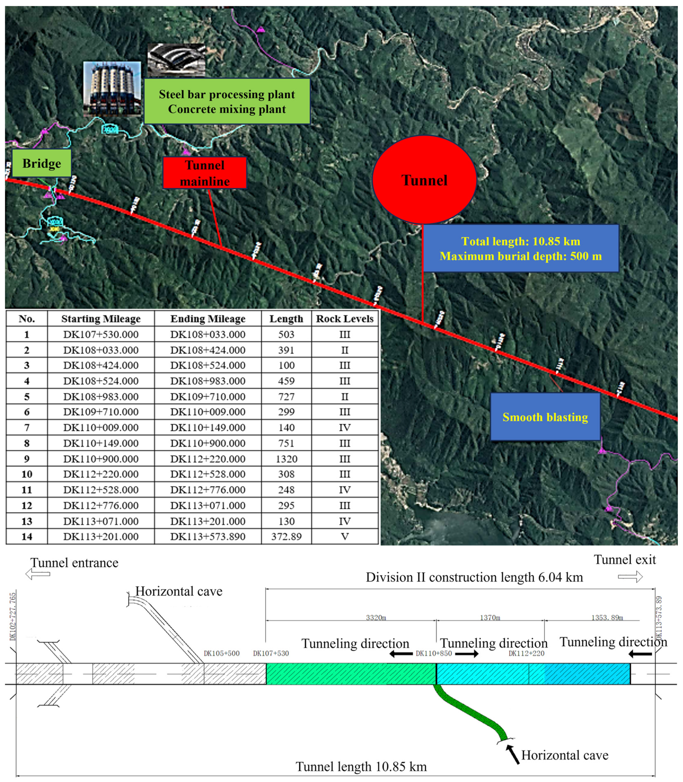
Figure 1. The tunnel project roadmap and layout plan.
Fractalfract 07 00842 g001
Figure 2. Blasting effect of the original design drill and blast method of construction.
Fractalfract 07 00842 g002
Figure 3. Flowchart of this study.
Fractalfract 07 00842 g003
Figure 4. Arrangement of blast holes.
Fractalfract 07 00842 g004
Figure 5. Spaced decoupled charge structure.
Fractalfract 07 00842 g005
Figure 6. Bidirectional shaped charge structure (physical drawing of shaped charge tube and water bag).
Fractalfract 07 00842 g006
Figure 7. Measurement of overbreak and underbreak of the tunnel section: (a) measurement design drawing; and (b) field implementation drawing.
Fractalfract 07 00842 g007
Figure 8. Flowchart of MF-DFA calculation.
Fractalfract 07 00842 g008
Figure 9. The effect of spaced decoupled charge of smooth blasting: (a) overall diagram of half-hole trace; and (b) detail diagram of half-hole trace.
Fractalfract 07 00842 g009
Figure 10. Bidirectional shaped charge blasting effect of smooth blasting diagram: (a) overall diagram of half-hole trace; and (b) detail diagram of half-hole trace.
Fractalfract 07 00842 g010
Figure 11. Scanning results of tunnel profile after blasting with two charge methods: (a) spaced decoupled charge, and (b) bidirectional shaped charge.
Fractalfract 07 00842 g011
Figure 12. Distribution curve of overbreak and underbreak of the profile of the blasting tunnel section for two charge methods: (a) spaced decoupled charge, and (b) bidirectional shaped charge.
Fractalfract 07 00842 g012
Figure 13. q-order wave function F q s s double logarithmic fitting trend image: (a) spaced decoupled charge, and (b) bidirectional shaped charge.
Fractalfract 07 00842 g013
Figure 14. Variation of the generalized Hurst index: (a) spaced decoupled charge, and (b) bidirectional shaped charge.
Fractalfract 07 00842 g014
Figure 15. Variation of the scalar function τ q : (a) spaced decoupled charge, and (b) bidirectional shaped charge.
Fractalfract 07 00842 g015
Figure 16. Multifractal spectra: (a) spaced decoupled charge, and (b) bidirectional shaped charge.
Fractalfract 07 00842 g016
Table 1. Perimeter rock compressive strength test results.
Specimen NumberSpecimen 1Specimen 2Specimen 3Specimen 4Average Value
Compressive strength106.0 MPa119.1 MPa129.1 MPa120.3 MPa118.6 MPa
Table 2. Parameter settings of the shell hole.
EventBlasthole Depth (m)Number of Holes Number of Rolls
per Hole
(Rolls/Hole)
Charge of
Single Hole
(kg/Hole)
Subtotal
Dosage
(kg)
Total
Number of
Holes
Total Amount
of Explosives
(kg)
Cut hole4.43414.52.998.6252437.1
Auxiliary hole4.2139102278
Peripheral hole4.2652.50.532.5
Floor hole4.21410228
Table 3. Comparison of the effects of spaced decoupled faceted blasting and bidirectional shaped charge blasting technology.
Sports EventSpaced Decoupled Charge Smooth
Blasting
Bidirectional Shaped Charge
BSmooth Blasting
Efficiencies
Number of smooth holes6551Decrease 21.5%
Semi-porous trace rate/%5689Increase 59.9%
Peripheral hole explosives/kg32.530.6Decrease 5.8%
Maximum unevenness/cm3010Decrease 66.7%
Amount of concrete m3/m13.014.61Decrease 64.6%
Table 4. Multifractal characterization statistics.
Cross-SectionCross-Section 1Cross-Section 2Cross-Section 3Cross-Section 4Cross-Section 5Cross-Section 6
Index
Δ α 0.5590.6950.7460.7340.7370.818
Δ f α 0.1330.1960.1370.2220.2920.644
Disclaimer/Publisher’s Note: The statements, opinions and data contained in all publications are solely those of the individual author(s) and contributor(s) and not of MDPI and/or the editor(s). MDPI and/or the editor(s) disclaim responsibility for any injury to people or property resulting from any ideas, methods, instructions or products referred to in the content.