Article

Modeling and Control Research of Fractional-Order Cascaded H-Bridge Multilevel STATCOM

School of Electrical Engineering, Guangxi University, Nanning 530004, China
*
Authors to whom correspondence should be addressed.
Fractal Fract. 2024, 8(7), 392; https://doi.org/10.3390/fractalfract8070392
Submission received: 21 May 2024 / Revised: 13 June 2024 / Accepted: 14 June 2024 / Published: 29 June 2024

Abstract

:
This paper introduces fractional-order capacitors and fractional-order inductors into the conventional integer-order cascaded H-bridge multilevel static compensator (ICHM-STATCOM), thereby constructing the main circuit of the fractional-order cascaded H-bridge multilevel static compensator (FCHM-STATCOM). Mechanism-based modeling is employed to establish switching function models and low-frequency dynamic models for the FCHM-STATCOM in the three-phase stationary coordinate system (a-b-c). Subsequently, fractional-order rotating coordinate transformation is introduced to establish the mathematical model of the FCHM-STATCOM in the synchronous rotating coordinate system (d-q). Additionally, a fractional-order proportional-integral (FOPI)-based fractional-order dual closed-loop current decoupling control strategy is proposed. Finally, this paper validates the correctness of the established mathematical models through digital simulation. Moreover, the simulation results demonstrate that by appropriately selecting the order of fractional-order capacitors and fractional-order inductors, the FCHM-STATCOM exhibits superior dynamic and static characteristics compared to the conventional ICHM-STATCOM, and the FCHM-STATCOM provides a more flexible reactive power compensation solution for power systems.

1. Introduction

Fractional calculus is a mathematical tool that is both ancient and novel [1,2]. With the rapid development and application of fractional-order calculus theory, the modeling, analysis, and control of fractional-order circuits have gradually become hot topics in research.
Capacitors and inductors are fundamental components of electrical circuits, and their performance significantly influences the operational characteristics of the circuits. Increasing research indicates that capacitors and inductors inherently possess fractional-order characteristics [3,4,5,6]. However, in conventional studies, they are modeled and analyzed as integer-order components, which may lead to significant discrepancies between theoretical analyses and actual characteristics. Meanwhile, scholars continue to propose methods for manufacturing capacitors and inductors with specific fractional orders, laying a solid foundation for the research of fractional-order circuits.
In recent years, scholars have applied fractional-order capacitors and inductors to power electronic converters, introducing fractional-order Boost converters, fractional-order PWM rectifiers, fractional-order PWM inverters, and other fractional-order power electronic converters. They have also conducted related research on fractional-order modeling, analysis, and control [7,8,9,10].
Considering the fractional-order capacitors and fractional-order inductors, Ref. [6] has established the fractional-order large-signal and small-signal models using the state-space averaging method and the Caputo–Fabrizio definition, respectively. Through transfer function simulation, it has been verified that fractional-order capacitors and fractional-order inductors have a significant impact on the steady-state characteristics of the Boost converter. Ref. [7] models a fractional-order Boost converter operating in continuous conduction mode (CCM) using the equivalent small parameter method and constructs a simulation model of the fractional-order Boost converter. It is found that the operating state of the fractional-order Boost converter is related to the order of the fractional-order capacitor and inductor.
Refs. [8,9] respectively constructed the fractional-order circuit topologies for single-phase and three-phase PWM rectifiers and established corresponding fractional-order PWM rectifier models based on the Caputo definition of fractional calculus. Simulation experiments conducted on this basis revealed that by appropriately configuring the orders of the fractional-order capacitors and inductors, superior dynamic and static performance could be achieved compared to integer-order PWM rectifiers. Furthermore, ref. [10] constructed the fractional-order circuit topology for a three-phase photovoltaic grid-connected inverter and established a corresponding fractional-order inverter model. Subsequently, simulation experiments demonstrated that the fractional-order photovoltaic inverter exhibited improved grid-connection performance.
The research findings on the aforementioned power electronic converters indicate that, compared to traditional integer-order modeling methods, fractional-order modeling approaches that consider the fractional-order characteristics of capacitors and inductors are able to more accurately describe the overall characteristics of the system. Utilizing fractional-order models for scientific research allows for a more realistic reflection of the actual operating conditions of the converters [11,12,13,14,15].
With the development of sustainable energy, the large-scale integration of renewable energy stations, represented by wind and photovoltaic stations, into the grid poses severe challenges to the power quality and stable operation of electrical systems [16,17,18]. Reactive power compensation is one of the methods to improve the power quality of the electrical power system and to maintain its stable operation [19]. Research and engineering practices have demonstrated that installing reactive power compensation devices at the common connection points of new energy stations significantly improves the quality of electrical power and enhances the stability of power systems [20,21,22]. The cascaded H-bridge multilevel static reactive power compensator (CHM-STATCOM) is a type of power electronic converter commonly used as a source of reactive power. The CHM-STATCOM is characterized by its simple structure, fast reactive power adjustment, desirable output performance, and transformer-less design. It is commonly used in high-voltage, large-capacity situations [23,24,25,26].
Currently, the fractional-order controllers commonly used in STATCOMs primarily include a fractional-order proportional integral (FOPI) controller and a fractional-order sliding mode controller. Ref. [27] introduces an FOPI controller to construct the control system for the STATCOM, and simulation experiments based on this have revealed that, compared with using traditional integer-order controllers, STATCOMs equipped with fractional-order controllers are more effective in reducing sub-synchronous oscillations in flexible DC transmission systems. Based on the Riemann–Liouville definition, ref. [28] constructs a fractional-order sliding mode controller. Simulation experiments conducted on this basis demonstrated that, compared to integer-order controllers, STATCOMs using fractional-order sliding mode controllers not only exhibit better dynamic performance but also further enhance the power quality of electrical systems. The research findings from references [26,27] indicate that, compared to STATCOMs utilizing traditional integer-order controllers, STATCOMs employing fractional-order controllers exhibit superior dynamic characteristics and are able to more flexibly meet the reactive power demands of the electrical power system.
Currently, research on fractional-order controllers primarily focuses on the domain of “integer-order controlled objects + fractional-order control”. There is less research concerning “fractional-order controlled objects + fractional-order control”. Therefore, this paper is based on the fractional-order characteristics of capacitors and inductors and primarily investigates the mechanism modeling and fractional-order control issues of the FCHM-STATCOM. The main contributions of this paper are as follows:
  • A new circuit topology of the FCHM-STATCOM is proposed in this paper.
  • This paper establishes the mathematical model of FCHM-STATCOM in both the three-phase stationary coordinate system and the synchronous rotating coordinate system. The models of STATCOMs are extended from the integer-order domain to the fractional-order domain.
  • This paper proposes an FOPI-based fractional-order dual closed-loop current decoupling control strategy for the FCHM-STATCOM that integrates fractional-order control with fractional-order circuits.
  • The digital simulation conducted in this paper demonstrates that the FCHM-STATCOM exhibits superior dynamic and static characteristics compared to the conventional ICHM-STATCOM.
The subsequent sections of this paper are organized as follows: Section 2 provides a brief introduction to the Caputo definition of fractional calculus, as well as fractional-order capacitors and inductors. In Section 3, the mathematical models of the FCHM-STATCOM under the three-phase stationary coordinate system (a-b-c) and the synchronous rotating coordinate system (d-q) are established. In Section 4, a fractional-order dual closed-loop current decoupling control strategy based on FOPI is proposed. In Section 5, a digital simulation is conducted to validate the correctness of the established mathematical models and analyze the impact of fractional-order capacitors and inductors on the operational characteristics of the FCHM-STATCOM. Section 6 provides a conclusion and an outlook for the FCHM-STATCOM.

2. A Brief Introduction of Caputo Fractional Calculus and Fractional-Order Com-Ponent

Due to the advantages of Caputo fractional calculus, such as low dependence on initial values, ease of Laplace transformation, the fractional derivative of a constant being zero, and simplicity in computation, Caputo fractional calculus is widely applied in the field of engineering research [1,29]. This paper will conduct research and analysis on the FCHM-STATCOM based on the Caputo fractional-order calculus definition.
For a function y ( t ) , the definition of Caputo fractional differential is defined as follows [29]:
D t α t 0 C y ( t ) = 1 Γ ( m α ) t 0 t y m ( τ ) ( t τ ) 1 + α m d τ
where t is an independent variable; t 0 is the lower bound of t; D denotes fractional calculus operator; C denotes the Caputo fractional differential; α is differential order, α R + ; m 1 < α < m , m N ; Γ ( ) denotes the Gamma function [29].
The Caputo fractional integral of a function y ( t ) is defined as [29]:
D t γ t 0 C y ( t ) = 1 Γ ( γ ) t 0 t y ( τ ) ( t τ ) 1 γ d τ
where γ is integral order, γ R + .
Figure 1 shows the circuit topology of the fractional capacitor and fractional inductor. In Figure 1 C and L denote the capacitance and inductance values of fractional-order capacitors and fractional-order inductors, respectively. β and α denote the order of fractional-order capacitors and fractional-order inductors, respectively.
The mathematical models for the fractional-order capacitor and fractional-order inductor are given by:
C d β u C d t β = i C
L d α i L d t α = u L
where u C and u L denote the voltage of fractional-order capacitors and fractional-order inductors, respectively; i C and i L denote the current of fractional-order capacitors and fractional-order inductors, respectively. Specifically, when β = α = 1 , fractional-order capacitors and fractional-order inductors behave equivalently to integer-order capacitors and inductors.

3. Modeling of FCHM-STATCOM

3.1. A Brief Description of the Circuit Topology of the FCHM-STATCOM

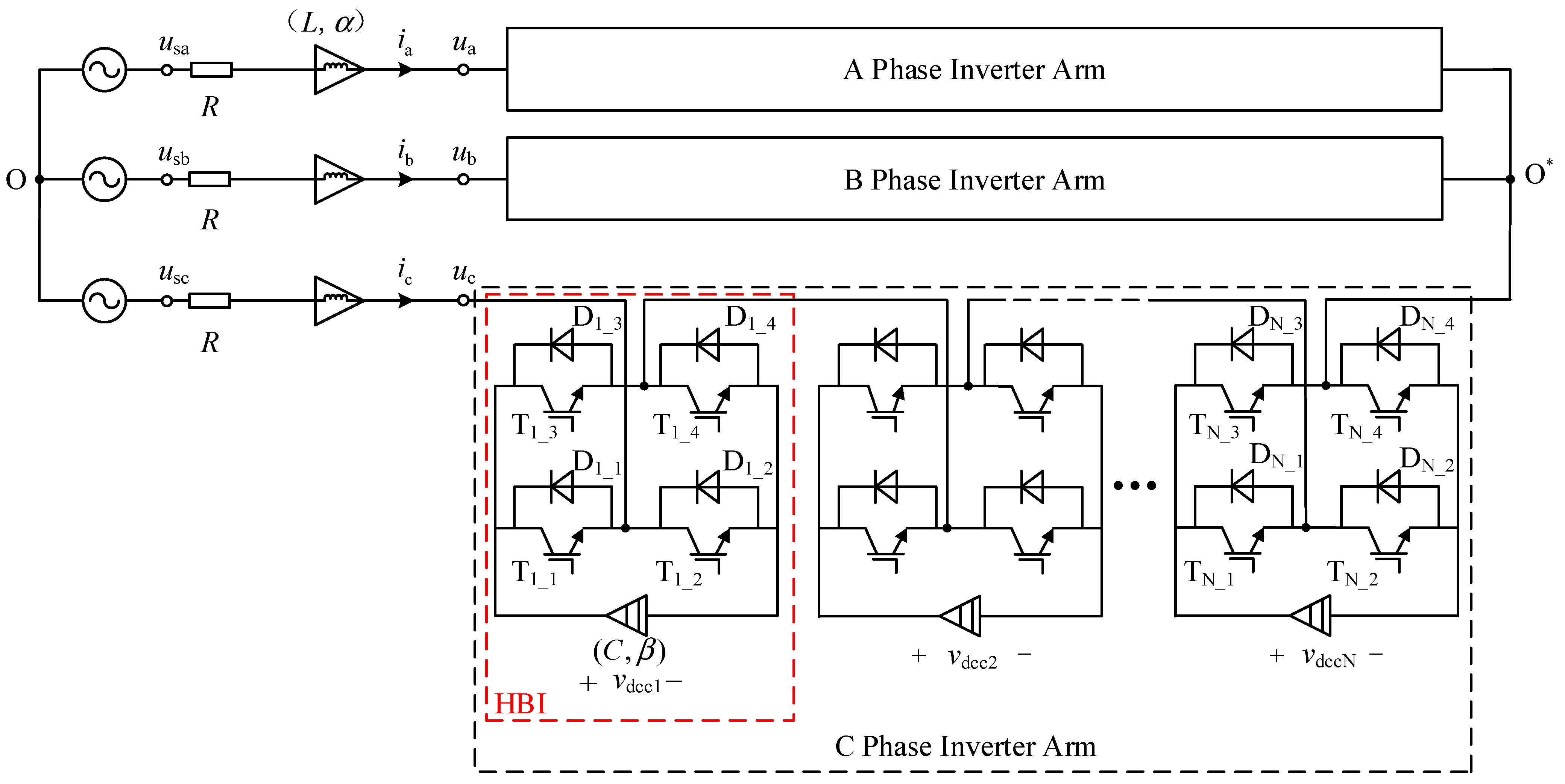
Figure 2 shows the topological structure of the FCHM-STATCOM. In Figure 2, the capacitors and inductors are both fractional-order components. Each phase of the converter arm consists of k ( k = 1 , 2 , 3 N ) H-bridge inverters (HBI) connected in series. u sa , u sb , u sc denote the phase voltages of the three-phase power grid; i a , i b , i c denote the input current of FCHM-STATCOM; u a , u b , u c denote the output voltage of FCHM-STATCOM; v dcc 1 , v dcc 2 v dccn denote DC side capacitor voltage; R denotes equivalent loss resistance, which is used to modify the active power losses in the AC-side filter reactors and the FCHM-STATCOM during actual operation. L denotes the inductance value of the AC-side filter reactors. C denotes the capacitance value of DC side capacitors; β and α denote the order of fractional-order capacitors and fractional-order inductors, respectively; T k _ x denotes the x-th IGBT of the k-th HBI; D k _ x denotes the x-th freewheeling diode of the k-th HBI; O denotes the neutral point of the power grid; O * denotes the neutral point of FCHM-STATCOM (For more detailed explanations of the symbols in this paper, see Appendix A).
In the HBI circuit shown in Figure 2. The triggering signal of T k _ 1 is complementary to the triggering signal of T k _ 2 ; the triggering signal of T k _ 3 is complementary to the triggering signal of T k _ 4 . The relationship between T k _ 1 , T k _ 2 and T k _ 3 , T k _ 4 can be expressed as:
{ s T k _ 1 = s ˜ T k _ 2 s T k _ 3 = s ˜ T k _ 4
where s T k _ 1 ~ s T k _ 4 denote the triggering signal of T k _ 1 ~ T k _ 4 .
According to (5), the switching function of HBI can be expressed as:
s jk = { 1 ( T k _ 1   is   on   , T k _ 4   is   on ) 0   ( T k _ 1   is   on   ,   T k _ 3   is   on   or   T k _ 2   is   on   , T k _ 4   is   on ) 1 ( T k _ 2   is   on   , T k _ 3   is   on   )
where j = ( a , b , c ) denotes the j-phase; k denotes the k-th HBI.
The mathematical models of the FCHM-STATCOM can be divided into three types: The switching function model, the average model, and the low-frequency dynamic model. By introducing switching functions, the switching function model is able to accurately describe the switching process of the FCHM-STATCOM. This model is typically utilized for analyzing the harmonic characteristics and selecting the modulation strategy of the FCHM-STATCOM. However, the complexity of the model leads to it being unsuitable for the design of controllers. The average model builds on the switching function model by approximating the switching function with a duty cycle. The role of the average model is similar to that of the switching function model. The low-frequency dynamic model, based on the switching function model, ignores the switching process and high-frequency components, retaining only the fundamental frequency components, making it directly applicable to controller design. This paper will establish both the switching function model and the low-frequency dynamic model for the FCHM-STATCOM.

3.2. The Switching Function Model of the FCHM-STATCOM

Based on Kirchhoff’s voltage (KVL) and current (KCL) laws, the mathematical model of the FCHM-STATCOM can be derived as follows:
{ L d α i j d t α + R i j = u sj u j u O * O u j = k = 1 N s jk v dcjk ( j = a , b , c )
where v dcjk denotes the DC-side capacitor voltage of the k-th HBI in phase j. u O * O denotes the voltage between the grid neutral point O and the FCHM-STATCOM neutral point O * .
There is no neutral wire connection between O and O * . When the FCHM-STATCOM is at a three-phase balanced condition at the point of common coupling (PCC), the grid voltages and input currents will present the following relationship: i a + i b + i c = 0 , u sa + u sb + u sc = 0 . Therefore, in (7), u O * O can be expressed as:
u O * O = k = 1 N s ak v dcak + k = 1 N s bk v dcbk + k = 1 N s ck v dcck 3
Combining (7) and (8), the switching function model of the FCHM-STATCOM in the three-phase stationary coordinate system can be derived as follows:
{ L d α i a d t α + R i a = u sa 1 3 ( 2 k = 1 N s ak v dcak k = 1 N s bk v dcbk k = 1 N s ck v dcck ) L d α i b d t α + R i b = u sb 1 3 ( 2 k = 1 N s bk v dcbk k = 1 N s ak v dcak k = 1 N s ck v dcck ) L d α i c d t α + R i c = u sc 1 3 ( 2 k = 1 N s ck v dcck k = 1 N s ak v dcak k = 1 N s bk v dcbk )   C d β v dcak d t β = i a s ak C d β v dcbk d t β = i b s bk C d β v dcck d t β = i c s ck
Under the condition of zero initial value, the Laplace transform of the Caputo fractional differential can be expressed as:
[ D t α C f ( t ) ] = s α F ( s )
where F ( s ) = [ f ( t ) ] .
The Laplace expression of (9) has the form as follows:
{ I a ( s ) = U sa ( s ) 1 3 [ 2 k = 1 N S ak ( s ) U dcak ( s ) k = 1 N S bk U dcbk ( s ) k = 1 N S ck U dcck ( s ) ] L s α + R I b ( s ) = U sb ( s ) 1 3 [ 2 k = 1 N S bk ( s ) U dcbk ( s ) k = 1 N S ak U dcak ( s ) k = 1 N S ck U dcck ( s ) ] L s α + R I c ( s ) = U sc ( s ) 1 3 [ 2 k = 1 N S ck ( s ) U dcck ( s ) k = 1 N S ak U dcak ( s ) k = 1 N S bk U dcbk ( s ) ] L s α + R U dcak ( s ) = I a ( s ) S ak ( s ) C s β U dcbk ( s ) = I b ( s ) S bk ( s ) C s β U dcck ( s ) = I c ( s ) S ck ( s ) C s β
where U dcjk ( s ) denotes the Laplace expression of v dcjk .
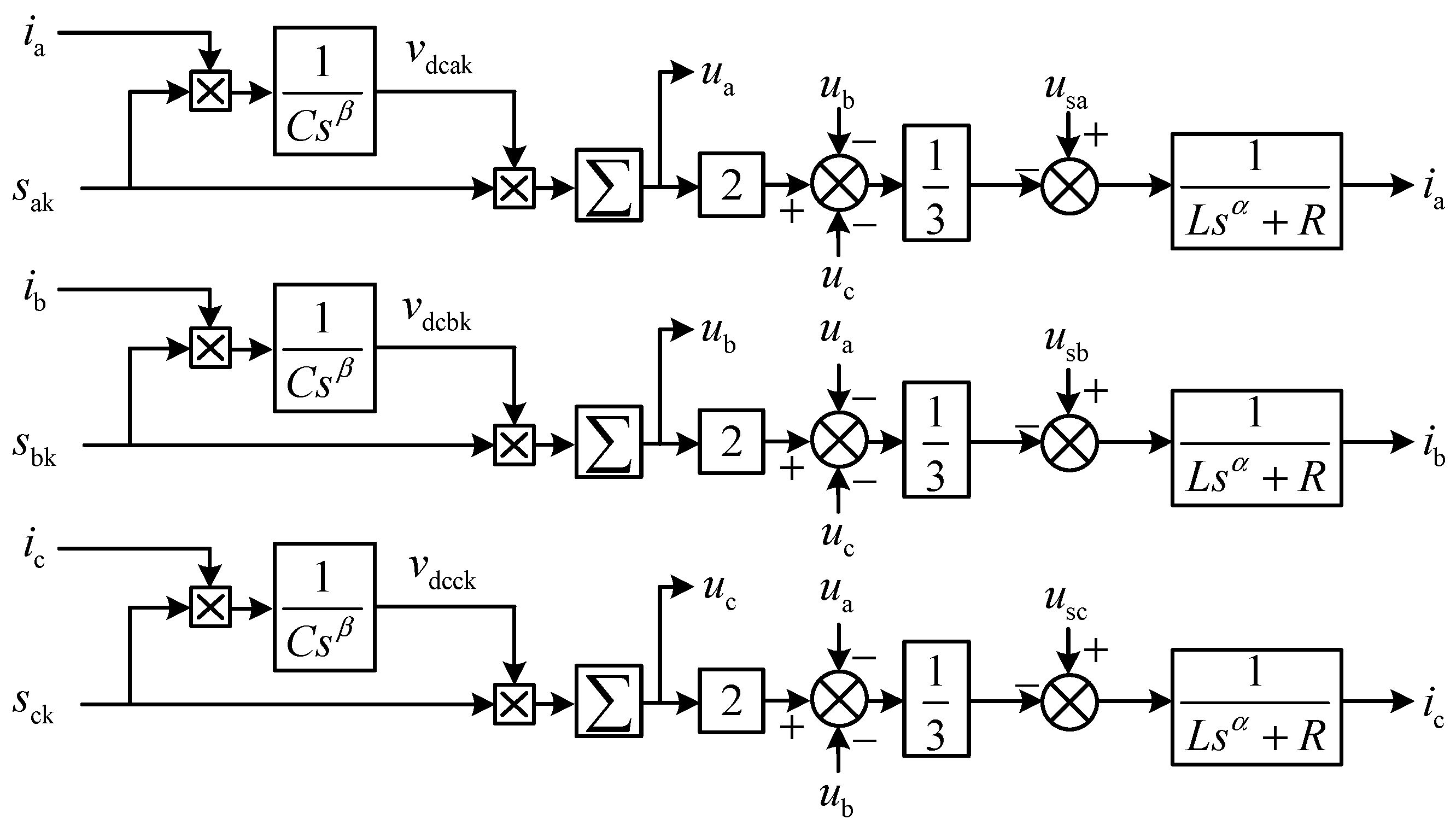
According to (9) and (11), the structure of the switching function model for the FCHM-STATCOM in the three-phase stationary coordinate system (a-b-c) can be obtained, as shown in Figure 3.
To facilitate the construction of the control system, this paper proposes a method of fractional-order coordinate transformation. By incorporating Caputo-type fractional calculus into the Park transformation, the Park transformation matrix can be directly applied to fractional-order models.
For the convenience of analysis, it is assumed that the average value of the total DC voltage on the three-phase DC side can be expressed as [30]:
u dcm = ( | u dca | + | u dcb | + | u dcc | ) / 3
where u dcm denotes the average value of the total DC voltage on the three-phase DC side; u dca , u dcb , u dcc denote the sum of the voltages on the individual DC sides of each phase which can be expressed as: u dcj = k = 1 N s jk v dcjk       ( j = a , b , c ) , | u dcj | denotes the amplitude of u dcj .
Combining (9) and (12), the switching function model in the three-phase stationary coordinate system is able to be equivalently represented in the following vector form:
{ L [ d α i a d t α d α i b d t α d α i c d t α ] + R [ i a i b i c ] = [ u sa u sb u sc ] [ s a u dca s b u dcb s c u dcc ] 3 C d β u dcm d t β = [ s a s b s c ] [ i a i b i c ]
where s j = k = 1 N s jk       ( j = a , b , c ) .
The transformation matrix from the three-phase stationary coordinate system to the synchronous rotating coordinate system (Park transformation) is given by:
P = T abc / dq 0 = 2 3 [ cos ω t cos ( ω t 2 π 3 ) cos ( ω t + 2 π 3 ) sin ω t sin ( ω t 2 π 3 ) sin ( ω t + 2 π 3 ) 1 2 1 2 1 2 ]
Substituting (14) into (13), the result can be expressed as:
{ L P [ d α i a d t α d α i b d t α d α i c d t α ] + R P [ i a i b i c ] = P [ u sa u sb u sc ] P [ s a u dca s b u dcb s c u dcc ] 3 C P d β u dcm d t β = P [ s a s b s c ] [ i a i b i c ]
Given the differential criterion as:
L P d α i abc d t α = L d α ( P i abc ) d t α L d α P d t α i abc = L d α ( i dq ) d t α L d α P d t α P 1 i dq
where i abc = [ i a i b i c ] T and i dq = [ i d i q ] T .
Based on the Caputo fractional-order differential definition, the fractional-order differential form of the Park transformation matrix presented in (14) can be expressed as follows:
d α P d t α = 2 3 [ ω α cos ( ω t + α π 2 ) 1 2 ω α cos ( ω t + α π 2 ) + 3 2 ω α sin ( ω t + α π 2 ) 1 2 ω α cos ( ω t + α π 2 ) 3 2 ω α sin ( ω t + α π 2 ) ω α sin ( ω t + α π 2 ) 1 2 ω α sin ( ω t + α π 2 ) + 3 2 ω α cos ( ω t + α π 2 ) 1 2 ω α sin ( ω t + α π 2 ) 3 2 ω α cos ( ω t + α π 2 ) 0 0 0 ]
The Park inverse transformation matrix is given by:
P 1 = T dq / abc = [ cos ω t sin ω t 1 cos ( ω t 2 π 3 ) sin ( ω t 2 π 3 ) 1 cos ( ω t + 2 π 3 ) sin ( ω t + 2 π 3 ) 1 ]
Based on Equations (15)–(18), the switching function model of the FCHM-STATCOM in the synchronous rotating coordinate system can be derived as follows:
{ L d α i d d t α + ( R + ω α L cos π α 2 ) i d ω α L sin π α 2 i q = u sd s d u dcm L d α i q d t α + ( R + ω α L cos π α 2 ) i q + ω α L sin π α 2 i d = u sq s q u dcm C d β u dcm ( t ) d t β = 1 3 ( i d s d + i q s q )
where i d , i q denote the d-q components of i a , i b , i c ; u sd , u sq denote the d-q components of u sa , u sb , u sc ; s d , s q denote the d-q components of s a , s b , s c .
The Laplace expression of (19) has the form as follows:
{ L s α I d ( s ) + ( R + ω α L cos π α 2 ) I d ( s ) ω α L sin π α 2 I q ( s ) = U sd ( s ) S d ( s ) U dcm ( s ) L s α I q ( s ) + ( R + ω α L cos π α 2 ) I q ( s ) + ω α L sin π α 2 I d ( s ) = U sq ( s ) S q ( s ) U dcm ( s ) C s β U dcm ( s ) = 1 3 [ I d ( s ) S d ( s ) + I q ( s ) S q ( s ) ]
According to (20), the structure of the switching function model for the FCHM-STATCOM in the synchronous rotating coordinate system (d-q) can be obtained, as shown in Figure 4.

3.3. The Low-Frequency Dynamic Model of the FCHM-STATCOM

For the convenience of controller design, the low-frequency dynamic model ignores the switching process and high-frequency components, retaining only the fundamental frequency components.
When the AC side system is in a three-phase balanced state and the output voltage of each phase converter arm is also in a three-phase balanced state (with an equal number of HBIs conducting in each converter arm), it can be considered that u O * O = 0 . It is assumed that the fundamental frequency component of the switching function is expressed as: ε a ( t ) , ε b ( t ) , ε c ( t ) . Substituting the aforementioned conditions into (7), the low-frequency dynamic model of the FCHM-STATCOM can be derived as follows:
{ L d α i j d t α + R i j = u sj u j C d β v dcjk d t β = i j ε jk   ( j = a , b , c )
The Laplace expression of (21) has the form as follows:
{ I j ( s ) = U sj ( s ) U j ( s ) L s α + R U dcjk ( s ) = I j ( s ) E j k ( s ) C s β   ( j = a , b , c )
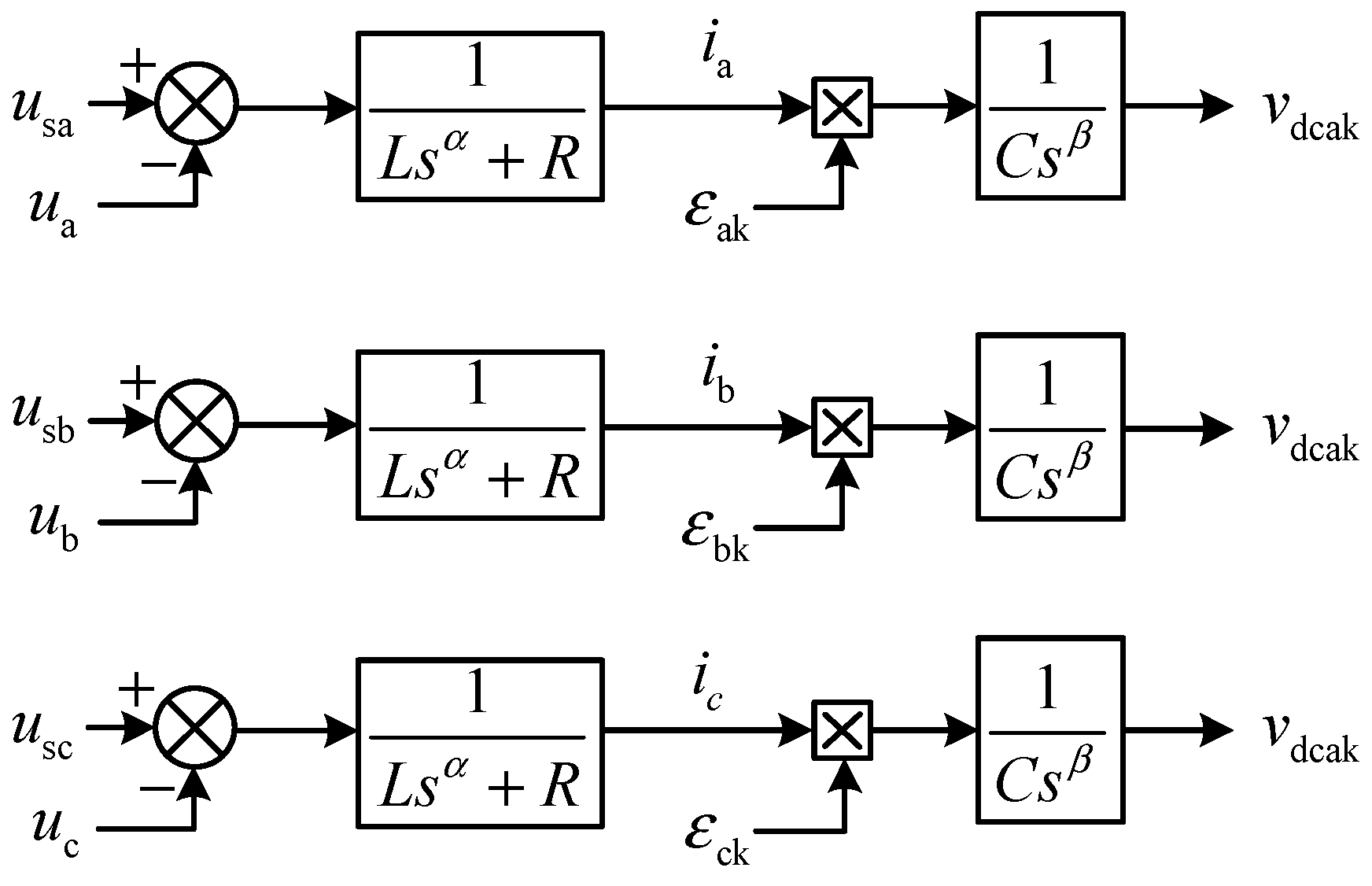
According to (21) and (22), the structure of the low-frequency dynamic model for the FCHM-STATCOM in the three-phase stationary coordinate system (a-b-c) can be obtained, as shown in Figure 5.
Applying the fractional-order coordinate transformation method to (21), the low-frequency dynamic model of the FCHM-STATCOM in the synchronous rotating coordinate system can be derived as follows:
{ L d α i d d t α + ( R + ω α L cos π α 2 ) i d ω α L sin π α 2 i q = u sd u d L d α i q d t α + ( R + ω α L cos π α 2 ) i q + ω α L sin π α 2 i d = u sq u q C d β u dcm d t β = 1 3 ( i d ε d + i q ε q )
where u d , u q denote the d-q components of u a , u b , u c ; ε d , ε q denote the d-q components of ε a , ε b , ε c .
The Laplace expression of (23) has the form as follows:
{ L s α I d ( s ) + ( R + ω α L cos π α 2 ) I d ( s ) ω α L sin π α 2 I q ( s ) = U sd ( s ) U d ( s ) L s α I q ( s ) + ( R + ω α L cos π α 2 ) I q ( s ) + ω α L sin π α 2 I d ( s ) = U sq ( s ) U q ( s ) C s β U dcm ( s ) = 1 3 [ I d ( s ) E d ( s ) + I q ( s ) E q ( s ) ]
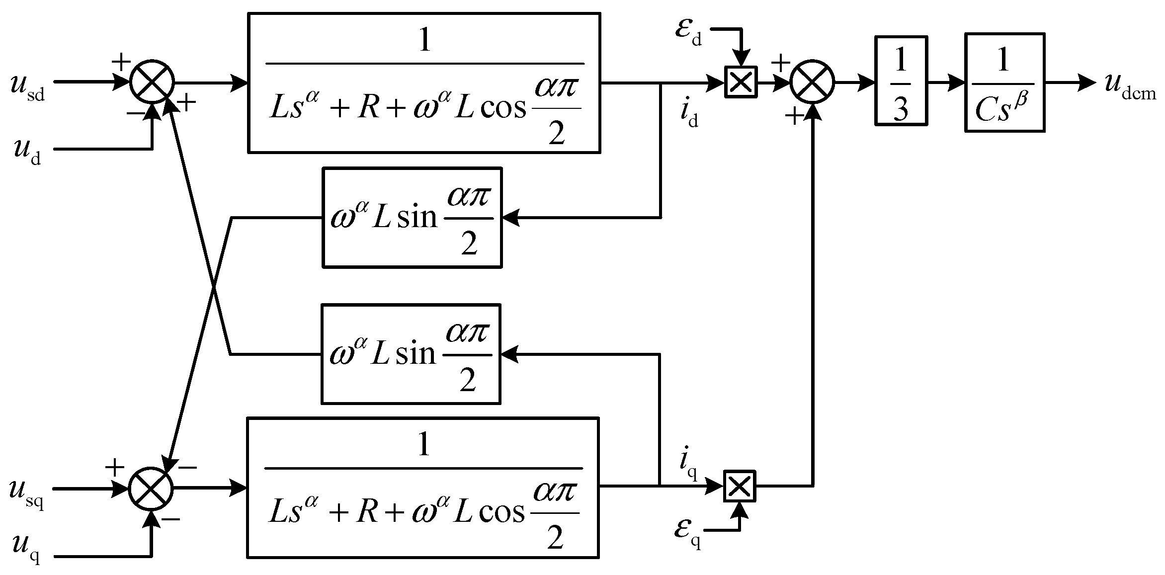
According to (24), the structure of the low-frequency dynamic model for the FCHM-STATCOM in the synchronous rotating coordinate system (d-q) can be obtained, as shown in Figure 6.

4. Fractional-Order Control Strategy of the FCHM-STATCOM

4.1. Current Inner Loop Design

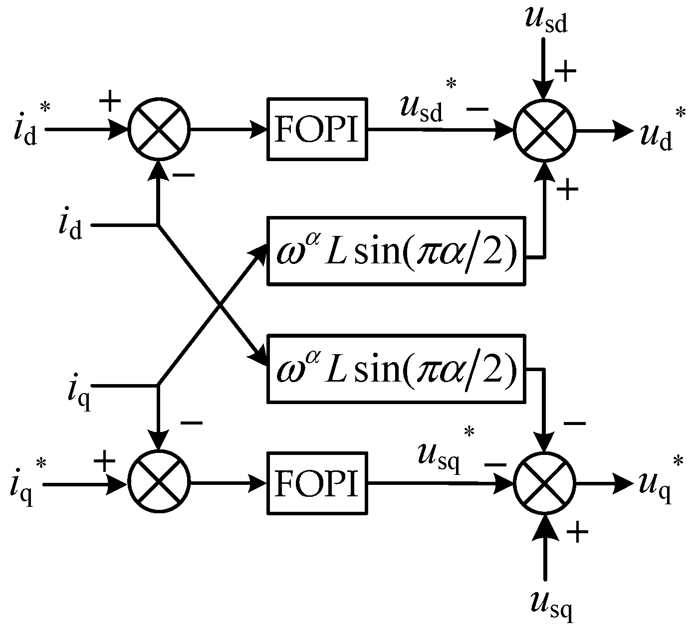
From (23), it is evident that there is a coupling between the d-q axes. To decouple, variables u sd * and u sq * are introduced as follows:
{ u sd * = u sd + ω α L sin π α 2 i q u d u sq * = u sq ω α L sin π α 2 i d u d
Combining (23) and (25), the mathematical model for the decoupled FCHM-STATCOM can be expressed as:
{ L d α i d d t α + ( R + ω α L cos π α 2 ) i d = u sd * L d α i q d t α + ( R + ω α L cos π α 2 ) i q = u sq *
The time-domain mathematical model of the FOPI controller can be expressed as:
y ( t ) = K P x ( t ) + K I x ( t ) d t λ
Utilizing an FOPI controller to achieve zero steady-state error tracking for u sd * and u sq * , the inner current loop of the FCHM-STATCOM controller can be established, as shown in Figure 7:

4.2. Design of the Outer Voltage Loop and Reactive Power Outer Loop

By calculating the total average of the capacitor voltages across all HBI in the three-phase converter arms, the variable u dc can be derived. By inputting the difference between u dc (a variable representing the reference value of the DC voltage outer loop controller) and u dc into the FOPI controller, the output i d can be obtained. In summary, the DC voltage outer loop of the FCHM-STATCOM controller can be derived, as shown in Figure 8.
According to the instantaneous reactive power theory, the power injected into the AC grid by the FCHM-STATCOM is expressed as follows:
q = 3 2 u sd i q
According to (28), the reactive power outer loop of the FCHM-STATCOM controller can be derived, as shown in Figure 9.
Based on the above analysis, The completed fractional-order control strategy of FCHM-STATCOM is given in Figure 10. The fractional-order control strategy consists of the current inner loop control as shown in Figure 7, the DC voltage outer loop control depicted in Figure 8, and the reactive power outer loop control illustrated in Figure 9. The structure of the FCHM-STATCOM shown in Figure 10 is a simplified form of that depicted in Figure 2. A carrier-phase-shifted SPWM (CPS-SPWM) modulation strategy is adopted in this paper.

5. Simulations and Analysis

In order to verify the correctness of the established FCHM-STATCOM mathematical models and analyze the impact of the orders of fractional-order capacitors and fractional-order inductors on the operating characteristics of the FCHM-STATCOM, this paper constructs the fractional-order capacitor and the fractional-order inductor simulation components based on the MATLAB/Simulink 2020b simulation platform, utilizing the high-precision Caputo operator and the Oustaloup filter principle from the FOTF toolbox [31]. A complete mathematical model of the FCHM-STATCOM is established based on the constructed fractional-order components, and a closed-loop simulation of the established simulation model is conducted using an FOPI controller. (See Table 1).
To study the impact of the order of fractional-order capacitors and fractional-order inductors on the operating characteristics of FCHM-STATCOM (See Table 2), this section sets up three different simulation schemes.
Simulation Scheme I: Keep the order of the fractional-order inductors constant, change the order of the fractional-order capacitors, and analyze the impact of the order of fractional-order capacitors on the operating characteristics of the FCHM-STATCOM.
Simulation Scheme II: Keep the order of the fractional-order capacitors constant, change the order of the fractional-order inductors, and analyze the impact of the order of fractional-order inductors on the operating characteristics of the FCHM-STATCOM.
Simulation Scheme III: Based on Simulation Schemes I and II, identify the FCHM-STATCOM with the optimal dynamic and static performance, and compare its operating characteristics with those of the ICHM-STATCOM.

5.1. Simulation Scheme I

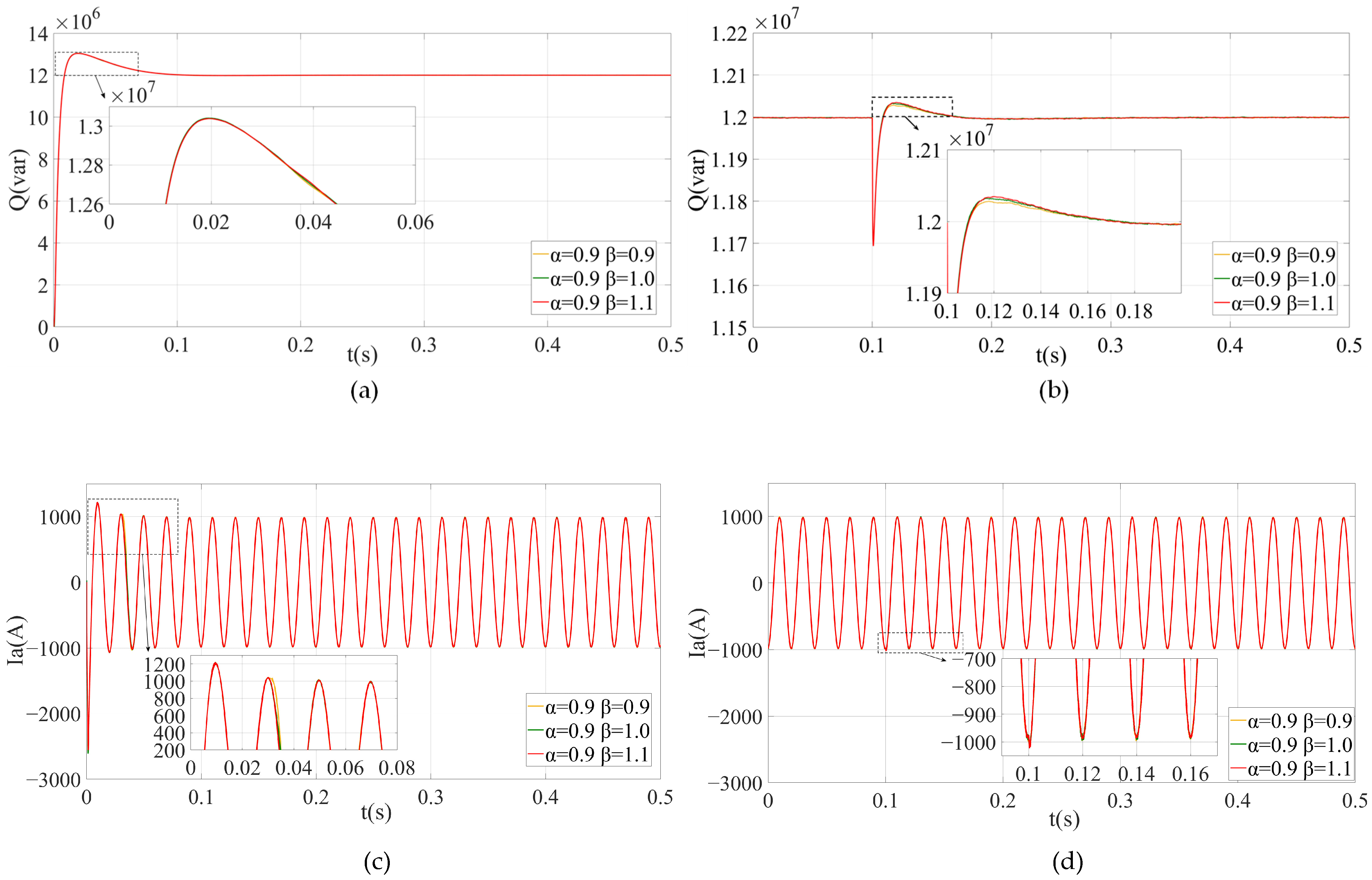
Scheme I maintains the order of the fractional-order inductor at 0.9, with the orders of the fractional-order capacitors being 0.9, 1, and 1.1 (See Table 3), respectively, to study the startup process and load disturbance process of the FCHM-STATCOM. The performance indicators verified by the simulation are the reactive power output (Q) of the FCHM-STATCOM, the output current (Ia) of phase A, and the average value of the DC-side voltage (Udc) of phase A.
From Figure 11 and Table 4, it can be observed that under similar control parameters, when the order of indicators remains constant:
(1)
During the startup process and load disturbance process of the FCHM-STATCOM, as the order of capacitors increases, the settling time, steady-state value, and overshoot of Q and Ia remain essentially unchanged.
(2)
During the startup process and load disturbance process of the FCHM-STATCOM, as the order of capacitors increases, the settling time of Udc decreases, the overshoot decreases, the static error decreases, the ripple peak-to-peak value of Udc significantly decreases, and the total harmonic distortion (THD) of Ia significantly decreases.
Therefore, it can be concluded that changes in the order of capacitors insignificantly affect the dynamic and static characteristics of Q and Ia, but primarily affect the dynamic and static characteristics of the DC side of the FCHM-STATCOM and the THD of Ia.

5.2. Simulation Scheme II

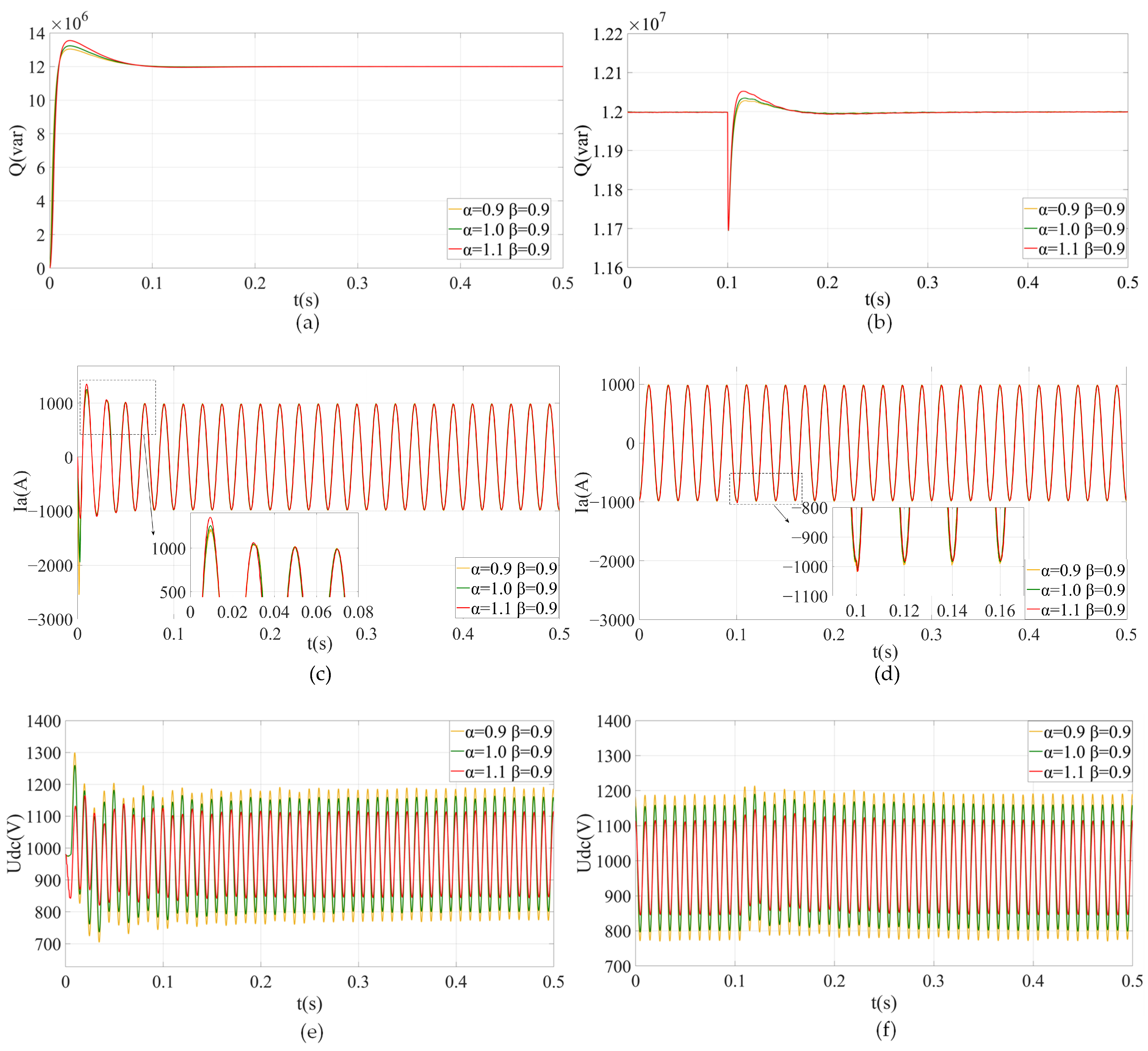
Scheme II maintains the order of the fractional-order capacitors at 0.9, with the orders of the fractional-order inductors being 0.9, 1, and 1.1, respectively, to study the startup process and load disturbance process of the FCHM-STATCOM. (See Table 5).
From Figure 12 and Table 6, it can be observed that under similar control parameters, when the order of capacitors remains constant:
(1)
During the start-up process of the FCHM-STATCOM, as the order of inductors increases, the steady-state value of Q remains essentially unchanged, while the overshoot and settling time increase. During the load disturbance process of the FCHM-STATCOM, as the order of inductors increases, the steady-state value, overshoot, and settling time of Q remain essentially unchanged.
(2)
During the start-up process of the FCHM-STATCOM, as the order of inductors increases, the static error and the overshoot of Ia decrease, the settling time of Ia slightly increases, the phase of Ia is delayed, and the total harmonic distortion (THD) of Ia decreases. During the load disturbance process of the FCHM-STATCOM, as the order of inductors increases, the static error, the overshoot, and the settling time of Ia increases, and the THD of Ia decreases.
(3)
During the start-up process of the FCHM-STATCOM, as the order of inductors increases, the static error, the overshoot, and the ripple peak-to-peak value of Udc decrease, and the settling time of Udc remains essentially unchanged. During the load disturbance process of the FCHM-STATCOM, as the order of inductors increases, the static error, the ripple peak-to-peak value, and the overshoot of Udc decrease, but the settling time of Udc remains essentially unchanged.
Therefore, it can be concluded that changes in the order of inductors primarily affect the dynamic and static characteristics of the AC side of the FCHM-STATCOM. Additionally, changes in the order of inductors indirectly influence the dynamic and static characteristics on the DC side of the FCHM-STATCOM by affecting the dynamic and static characteristics of Ia.

5.3. Simulation Scheme III

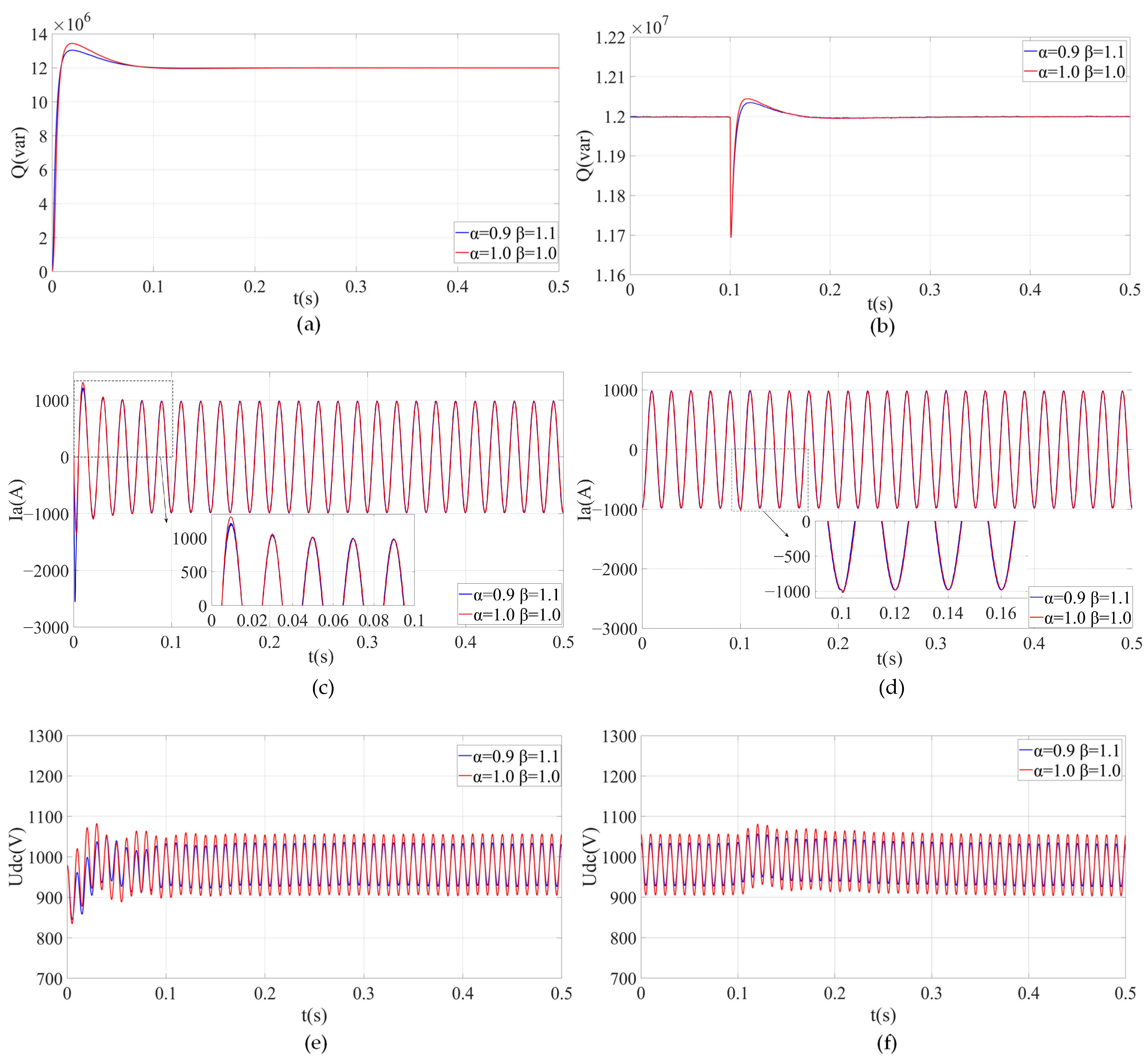
Scheme III selects an inductor order of 0.9, at which the overshoot of reactive power is minimized and the response speed is the fastest. Building on this, to further enhance the response speed of the FCHM-STATCOM and reduce the fluctuation of the DC voltage, Scheme III chooses a capacitor order of 1.1, resulting in the smallest peak-to-peak ripple of the DC side voltage and the fastest response speed (See Table 7). In summary, Scheme III intends to employ the order combination from Condition 3 for a comparison with the ICHM-STATCOM.
From Figure 13 and Table 8, it is observed that, compared to the ICHM-STATCOM, the FCHM-STATCOM with an inductor order of 0.9 and a capacitor order of 1.1 has the following advantages:
(1)
Faster reactive power response speed and lower overshoot.
(2)
The DC voltage response speed is faster, the overshoot is lower, the static error is minimized, and the steady-state ripple peak-to-peak is smaller, which lowers the requirement for the voltage withstand level of the DC-side capacitors.
(3)
The THD of the output current is lower and meets the standard of having a THD less than 4% for a 10 kV grid connection [32].
Considering the three simulation schemes mentioned above, it is evident that by selecting the appropriate order of fractional-order inductor and capacitor orders, an FCHM-STATCOM with superior dynamic and static characteristics compared to the traditional ICHM-STATCOM can be designed.

6. Conclusions

Based on the theory of fractional-order calculus, this paper considers the fractional-order characteristics of capacitors and inductors and employs a mechanism-based modeling approach to establish the switching function model and the low-frequency dynamic model of the FCHM-STATCOM in both the three-phase stationary coordinate system and the synchronous rotating coordinate system for the first time. Additionally, this paper proposes a fractional-order control strategy for the FCHM-STATCOM and designs the corresponding FOPI controller. The results of digital modeling and simulation experiments validate the correctness of the proposed modeling method and the established models. Research indicates that:
(1)
Employing a fractional-order model can more accurately describe the operational characteristics of the CHM-STATCOM. The integer-order model of the CHM-STATCOM is merely a special case of the fractional-order model, while the fractional-order model represents the general form of the CHM-STATCOM model. Simplifying the CHM-STATCOM into an integer-order model by neglecting the fractional-order properties of inductors and capacitors can lead to significant deviations in the established model.
(2)
Compared to the traditional integer-order models, the FCHM-STATCOM exhibits more flexible and diverse operational characteristics. By appropriately selecting the orders of the fractional-order capacitors and inductors, the FCHM-STATCOM can not only achieve superior dynamic and static performance but also provide the power system with reactive power support that is faster, contains fewer harmonics, and is of higher quality.
(3)
When the fractional-order inductor order remains constant, effectively modifying the order of the fractional-order capacitor within a certain range can significantly improve the dynamic and static characteristics on the DC side of the FCHM-STATCOM. Conversely, when the fractional-order capacitor order is held constant, and the order of the fractional-order inductor is varied within a certain range, it can effectively enhance the dynamic and static characteristics on the AC side of the FCHM-STATCOM. Additionally, changes in the fractional-order inductor order also exert a certain degree of influence on the dynamic and static characteristics of the DC side of the FCHM-STATCOM.
Further research can be carried out from the following aspects (but not limited to):
(1)
For the FCHM-STATCOM model established in this paper, further analysis of the design issues for the fractional-order controller needs to be conducted. Additionally, it is necessary to make a detailed comparison between the fractional-order controller and the integer-order controller.
(2)
Based on (1), it is necessary to develop four types of closed-loop systems: “integer-order system + integer-order control”, “integer-order system + fractional-order control”, “fractional-order system + integer-order control”, and “fractional-order system + fractional-order control”. Additionally, a further comprehensive analysis of the impact of fractional-order elements and fractional-order controllers on the FCHM-STATCOM system needs to be conducted.

Author Contributions

Conceptualization, J.X.; data curation, J.X. and S.T.; formal analysis, S.T.; investigation, J.X. and S.T.; methodology, J.X., S.T. and G.H.; resources, G.H., Z.G., G.L. and J.L.; software, S.T., G.H. and Z.G.; supervision, J.X. and J.L.; validation, S.T. and G.H.; writing—original draft, J.X.; writing—review and editing, G.L. All authors have read and agreed to the published version of the manuscript.

Funding

This research received no external funding.

Data Availability Statement

The original contributions presented in the study are included in the article, further inquiries can be directed to the corresponding authors.

Conflicts of Interest

The authors declare no conflict of interest.

Appendix A

Table A1. The characteristics of the electrical symbols.
CharacteristicElectrical Symbols
AC component u sj ( j = a , b , c )
i j ( j = a , b , c )
u j ( j = a , b , c )
u O * O
u dcj ( j = a , b , c )
DC component v dcjk ( j = a , b , c ) ( k = 1 , 2 , 3 N )
u dcm
i d , i q
u sd , u sq
u d , u q
Table A2. The symbols before and after applying Laplace transform.
Symbols before Applying Laplace TransformSymbols after Applying Laplace Transform
u sj ( j = a , b , c ) U sj ( s ) ( j = a , b , c )
i j ( j = a , b , c ) I j ( s ) ( j = a , b , c )
u j ( j = a , b , c ) U j ( s ) ( j = a , b , c )
v dcjk ( j = a , b , c ) ( k = 1 , 2 , 3 N ) U dcjk ( s ) ( j = a , b , c ) ( k = 1 , 2 , 3 N )
s jk ( j = a , b , c ) ( k = 1 , 2 , 3 N ) S jk ( s ) ( j = a , b , c ) ( k = 1 , 2 , 3 N )
ε jk ( j = a , b , c ) ( k = 1 , 2 , 3 N ) E jk ( s ) ( j = a , b , c ) ( k = 1 , 2 , 3 N )
u dcm U dcm ( s )
i d , i q I d ( s ) , I q ( s )
u sd , u sq U sd ( s ) , U sq ( s )
u d , u q U d ( s ) , U q ( s )
s d , s q S d ( s ) , S q ( s )
ε d , ε q E d ( s ) , E q ( s )

References

  1. Podlubny, I. Fractional Differential Equations; Academic: New York, NY, USA, 1999. [Google Scholar]
  2. Mandelbort, B.B. The Fractal Geometry of Nature; Macmillan: New York, NY, USA, 1983. [Google Scholar]
  3. Allagui, A.; Freeborn, T.J.; Elwakil, A.S.; Fouda, M.E.; Maundy, B.J.; Radwan, A.G.; Said, Z.; Abdelkareem, M.A. Review of fractional-order electrical characterization of supercapacitors. J. Power Sources 2018, 400, 457–467. [Google Scholar] [CrossRef]
  4. Chen, X.; Xi, L.; Zhang, Y.; Ma, H.; Huang, Y.; Chen, Y. Fractional techniques to characterize non-solid aluminum electrolytic capacitors for power electronic applications. Nonlinear Dyn. 2019, 98, 3125–3141. [Google Scholar] [CrossRef]
  5. Elwakil, A.S.; Allagui, A.; Freeborn, T.J.; Maundy, B.J. Further experimental evidence of the fractional-order energy equation in supercapacitors. AEU—Int. J. Electron. Commun. 2017, 78, 209–212. [Google Scholar] [CrossRef]
  6. Xu, J.; Zeng, E.; Li, X.; He, G.; Liu, W.; Meng, X. Fractional-Order LCL Filters: Principle, Frequency Characteristics, and Their Analysis. Fractal Fract. 2024, 8, 38. [Google Scholar] [CrossRef]
  7. Yu, D.; Liao, X.; Wang, Y. Modeling and Analysis of Caputo–Fabrizio Definition-Based Fractional-Order Boost Converter with Inductive Loads. Fractal Fract. 2024, 8, 81. [Google Scholar] [CrossRef]
  8. Qiu, B.; Wang, X. Fractional-Order Modeling and Control of Coupled Inductance Boost Converter. In Proceedings of the 2021 8th International Conference on Electrical and Electronics Engineering (ICEEE), Antalya, Turkey, 9–11 April 2021. [Google Scholar]
  9. Xu, J.; Li, X.; Meng, X.; Qin, J.; Liu, H. Modeling and analysis of a single-phase fractional-order voltage source pulse width modulation rectifier. J. Power Sources 2020, 479, 228821. [Google Scholar] [CrossRef]
  10. Xu, J.; Li, X.; Liu, H.; Meng, X. Fractional-order modeling and analysis of a Three-phase Voltage Source PWM Rectifier. IEEE Access 2020, 8, 13507–13515. [Google Scholar] [CrossRef]
  11. Li, X.; Hou, L.; Luo, X.; Xu, J. Research on Fractional Modeling And Controller Design of Three-Phase Inverter Grid-Connected System. Acta Energ. Solaris Sin. 2023, 44, 415–424. [Google Scholar]
  12. Freeborn, T.J.; Maundy, B.; Elwakil, A. Fractional resonance-based RLβCα filters. Math. Probl. Eng. 2013, 2013, 726721. [Google Scholar]
  13. Radwan, A.G.; Salama, K.N. Fractional-order RC and RL circuits. Circuits Syst. Signal Process. 2012, 31, 1901–1915. [Google Scholar] [CrossRef]
  14. Elwakil, A.S. Fractional-order circuits and systems: An emerging interdisciplinary research area. IEEE Circuits Syst. Mag. 2010, 10, 40–50. [Google Scholar] [CrossRef]
  15. Diao, L.; Zhang, X.; Chen, D. Fractional-order multiple RL alpha C beta circuit. Acta Phys. Sin. 2014, 63, 038401. [Google Scholar] [CrossRef]
  16. Li, Y.; Liu, H.; Chi, Y.; Fan, Y.; Li, X.; Cheng, F.; Wang, Z.; Wei, C.; Xie, L. Fault Ride-through Demand of Large-scale Islanded Renewable Energy Connected to VSC-HVDC System and Its Key Technologies. In Proceedings of the 2020 4th International Conference on HVDC (HVDC), Xi’an, China, 6–9 November 2020. [Google Scholar]
  17. Xu, Z.; Jin, Y.; Li, S.; Zhang, Z. Analysis and treatment of harmonic resonance amplification mechanism of AC grid-connected offshore wind farms. Autom. Electr. Power Syst. 2021, 45, 85–91. [Google Scholar]
  18. Kouro, S.; Leon, J.I.; Vinnikov, D.; Franquelo, L.G. Grid-Connected Photovoltaic Systems: An Overview of Recent Research and Emerging PV Converter Technology. IEEE Ind. Electron. Mag. 2015, 9, 47–61. [Google Scholar] [CrossRef]
  19. Kumar, N.; Wagh, P.; Kolhe, D.; Arane, P.; Kadlag, P. Power quality improvement in distributed energy resources for EV charging using STATCOM. In Proceedings of the 2022 1st International Conference on Sustainable Technology for Power and Energy Systems (STPES), Srinagar, India, 4–6 July 2022. [Google Scholar]
  20. Chavan, P.M.; Chavan, G.P. Interfacing of hybrid power system to grid using statcom & power quality improvement. In Proceedings of the 2017 International Conference on Information, Communication, Instrumentation and Control (ICICIC), Indore, India, 17–19 August 2017. [Google Scholar]
  21. Zheng, C.H.; Wu, X. Quasi Resonant Sliding Mode Perturbation Observer of STATCOM for Harmonic Mitigation in Offshore Wind Farm. Proc. CSEE 2024, 1–16. [Google Scholar]
  22. Zhang, M.; Wang, Q.; Li, G. Study on robust current and neutral-point potential control for the D-STATCOM based on NPC three-level inverter. Proc. CSEE 2016, 36, 3868–3878. [Google Scholar]
  23. Xiao, M.; Wang, F.; He, Z.; Ouyang, H.; Hao, R.; Xu, Q. Power Control and Fault Ride-Through Capability Analysis of Cascaded Star-Connected SVG under Asymmetrical Voltage Conditions. Energies 2019, 12, 2361. [Google Scholar] [CrossRef]
  24. Rodriguez, E.; Leyva, R.; Liu, Q.; Townsend, C.D.; Farivar, G.G.; Ceballos, S.; Pou, J. Enhancing inductive operation of low-capacitance cascaded H-bridge STATCOMs using optimal third-harmonic circulating current. IEEE Trans. Power Electron. 2021, 36, 10788–10800. [Google Scholar] [CrossRef]
  25. Pan, H.B.; Zhu, H.; Xiao, Z. A novel DC voltage and reactive power balance control strategy for cascaded H bridge rectifier. Proc. CSEE 2017, 37, 3565–3573. [Google Scholar]
  26. Bakas, P.; Harnefors, L.; Norrga, S.; Nami, A.; Ilves, K.; Dijkhuizen, F.; Nee, H.P. A review of hybrid topologies combining line-commutated and cascaded full-bridge converters. IEEE Trans. Power Electron. 2017, 32, 7435–7448. [Google Scholar] [CrossRef]
  27. Koteswara, R.D.; Umre, B.S.; Junghare, A.S.; Thakre, M.P.; Motamarri, R.; Somu, C. Fractional-order PI based STATCOM and UPFC controller to diminish sub-synchronous resonance. SpringerPlus 2016, 5, 1599. [Google Scholar] [CrossRef]
  28. Ahmed, T.; Waqar, A.; Elavarasan, R.M.; Imtiaz, J.; Premkumar, M.; Subramaniam, U. Analysis of Fractional Order Sliding Mode Control in a D-STATCOM Integrated Power Distribution System. IEEE Access 2021, 9, 70337–70352. [Google Scholar] [CrossRef]
  29. Xue, D.Y. Fractional Calculus and Fractional-Order Control, 1st ed.; Science Press: Beijing, China, 2018. [Google Scholar]
  30. Oghorada, O.J.K.; Li, Z. Analysis of star and delta connected modular multilevel cascaded converter-based STATCOM for load unbalanced compensation. Int. J. Electr. Power Energy Syst. 2018, 95, 341–352. [Google Scholar] [CrossRef]
  31. Xue, D.Y. FOTF Toolbox. Available online: https://ww2.mathworks.cn/matlabcentral/fileexchange/60874-fotf-toolbox (accessed on 5 April 2024).
  32. Systems Aspects for Electrical Energy Supply GB/T 14549-1993; Quality of Electric Energy Supply—Harmonics Inpublic Supply Network. Standards Press of China: Beijing, China, 1993.
Figure 1. Fractional-order component. (a) Fractional capacitor. (b) Fractional inductor.
Fractalfract 08 00392 g001
Figure 2. The main circuit topology of FCHM-STATCOM.
Fractalfract 08 00392 g002
Figure 3. The structure of the switching function model for the FCHM-STATCOM in the three-phase stationary coordinate system (a-b-c).
Fractalfract 08 00392 g003
Figure 4. The structure of the switching function model for the FCHM-STATCOM in the synchronous rotating coordinate system (d-q).
Fractalfract 08 00392 g004
Figure 5. The structure of the low-frequency dynamic model for the FCHM-STATCOM in the three-phase stationary coordinate system (a-b-c).
Fractalfract 08 00392 g005
Figure 6. The structure of the low-frequency dynamic model for the FCHM-STATCOM in the synchronous rotating coordinate system (d-q).
Fractalfract 08 00392 g006
Figure 7. The inner current loop of the FCHM-STATCOM controller.
Fractalfract 08 00392 g007
Figure 8. The DC voltage outer loop of the FCHM-STATCOM controller.
Fractalfract 08 00392 g008
Figure 9. The reactive power outer loop of the FCHM-STATCOM controller.
Fractalfract 08 00392 g009
Figure 10. The completed fractional-order control strategy of the FCHM-STATCOM.
Fractalfract 08 00392 g010
Figure 11. Simulation results of Scheme I. (a) Simulation results of Q during the startup process. (b) Simulation results of Q during the load disturbance process. (c) Simulation results of Ia during the startup process. (d) Simulation results of Ia during the load disturbance process. (e) Simulation results of Udc during the startup process. (f) Simulation results of Udc during the load disturbance process.
Fractalfract 08 00392 g011aFractalfract 08 00392 g011b
Figure 12. Simulation results of Scheme II. (a) Simulation results of Q during the startup process. (b) Simulation results of Q during the load disturbance process. (c) Simulation results of Ia during the startup process. (d) Simulation results of Ia during the load disturbance process. (e) Simulation results of Udc during the startup process. (f) Simulation results of Udc during the load disturbance process.
Fractalfract 08 00392 g012
Figure 13. Simulation results of Scheme III. (a) Simulation results of Q during the startup process. (b) Simulation results of Q during the load disturbance process. (c) Simulation results of Ia during the startup process. (d) Simulation results of Ia during the load disturbance process. (e) Simulation results of Udc during the startup process. (f) Simulation results of Udc during the load disturbance process.
Fractalfract 08 00392 g013
Table 1. Main circuit parameter table of FCHM-STATCOM.
ParameterValue
Rated reactive power12 Mvar
Rated voltage10 kV
Grid frequency50 Hz
Cascaded number10
DC side capacitor5800 μ F
Initial DC voltage980 V
AC filter inductor6.2 mH
Soft start resistor300 Ω
Loss simulation resistor0.5 Ω
Table 2. Fractional order controller parameters (Note: The fractional-order control system in this paper is a per-unit value control system).
Controller ParametersKPKIλReferences
Parameters of reactive power outer loop24024,0001.21 p.u.
Parameters of DC voltage outer loop98098001.11 p.u.
Parameters of current inner loop28028001.3
Table 3. Simulation condition for Scheme I.
Simulation ConditionCondition 1Condition 2Condition 3
Order of inductors α 0.90.90.9
Order of capacitors β 0.91.01.1
Table 4. The performance indicators of Scheme I. (Note: The format for listing performance indicators is as follows: startup process metrics/load disturbance process metrics. Unless otherwise specified, this format will be used throughout the text.).
Performance IndicatorConditionSteady-State Value Overshoot
(%)
Settling Time
(s)
Ripple Peak-to-Peak Value of Udc
(V)
THD of Ia
(%)
Q (Mvar)Condition 112/128.7/0.290.0792/0.004
Condition 212/128.7/0.280.07930.004
Condition 312/128.7/0.240.0792/0.004
Ia (A)Condition 1698/69848.4/2.150.072/0.01860.68/0.69
Condition 2697/69748.4/2.150.0775/0.01840.22/0.35
Condition 3697/69748.4/2.150.0793/0.01820.2/0.2
Udc (V)Condition 1990/9907.7/2.40.183/0.139412.74/412.74
Condition 2982.2/982.25.1/2.40.155/0.133207.11/207.11
Condition 3980.8/980.81.2/2.30.126/0.129105.73/105.73
Table 5. Simulation Condition for Scheme II.
Simulation ConditionCondition 1Condition 4Condition 5
Order of inductors α 0.91.01.1
Order of capacitors β 0.90.90.9
Table 6. The performance indicators of Scheme II.
Performance IndicatorConditionSteady-State Value Overshoot
(%)
Settling Time
(s)
Ripple Peak-to-Peak Value of Udc
(V)
THD of Ia
(%)
Q (Mvar)Condition 112/128.7/0.290.0792/0.004
Condition 412/1212/0.30.08/0.004
Condition 512/1213/0.430.0812/0.0035
Ia (A)Condition 1698/69848.4/2.150.072/0.01860.68/0.69
Condition 4694.8/694.840.4/2.50.0793/0.02040.43/0.41
Condition 5692.8/692.834/2.70.0792/0.02080.39/0.37
Udc (V)Condition 1990/9907.7/2.40.183/0.139412.74/412.74
Condition 4988.3/988.37/2.70.19/0.141358.6/358.6
Condition 5984.7/984.73/2.70.182/0.114270.9/270.9
Table 7. Simulation condition for Scheme III.
Simulation ConditionCondition 3Condition 6
Order of inductors α 0.91.0
Order of capacitors β 1.11.0
Table 8. The performance indicators of Scheme III.
Performance IndicatorConditionSteady-State Value Overshoot
(%)
Settling Time
(s)
Ripple Peak-to-Peak Value of Udc
(V)
THD of Ia
(%)
Q (Mvar)Condition 312/128.7/0.240.082/0.004
Condition 612/1212/0.30.0792/0.004
Ia (A)Condition 3697/69748.4/2.150.072/0.01860.2/0.2
Condition 6693/69335/2.40.0793/0.01820.28/0.27
Udc (V)Condition 3980.8/980.81.2/2.30.111/0.132105.73/105.73
Condition 6982.1/982.118.5/2.30.095/0.115152.3/152.3
Disclaimer/Publisher’s Note: The statements, opinions and data contained in all publications are solely those of the individual author(s) and contributor(s) and not of MDPI and/or the editor(s). MDPI and/or the editor(s) disclaim responsibility for any injury to people or property resulting from any ideas, methods, instructions or products referred to in the content.